Modcan Synthesizer DO s and DON TS
|
|
|
- Claude Allison
- 5 years ago
- Views:
Transcription
1 Users M A N U A L

 within. 2/ DO return the synthesizer to Modcan for service in the event that it stops functioning.")
2 Modcan Synthesizer DO s and DON TS Thank you for purchasing Modcan products. Your Synthesizer was built by hand to exacting standards. To get the best long term performance from your system we suggest reading and following the guidelines listed below. Technical support questions can be submitted to info@modcan.com or call Modcan at Safety Issues: 1/ DON T open the power supply compartment. There are no user serviceable parts enclosed. There are components that use dangerous mains level voltage (120V or 230V) within. 2/ DO return the synthesizer to Modcan for service in the event that it stops functioning.individual modules can be returned if the problem is localized to one or two modules. 3/ DON T have the power switched on when rearranging or exchanging modules and preferably don t operate the synth with any module spaces left open. 4/ Grounding Issues: Resist the temptation to remove the ground pin from the power cord. This is an UNSAFE connection for electronic equipment. If ground loops are a problem, first try cutting the ground wire connection on one end (not both) of the 1 4 phone cable that connects the output of the synth to your mixer or amplifier. Also try making sure that both the synth and your mixer/amp or other equipment are plugged into the same wall socket, power bar or are at least on the same house circuit. If all else fails contact Modcan for other suggestions. 5/ Obviously, DON T use the synth while in the bath or swimming. Other methods can be used to achieve bubbly sounds during these activities. Operation Issues: 1/ Power up the synthesizer: switch on synth power first then power up mixer/amplifier. To power down: switch off mixer/amp first (or mute the appropriate channel) and then switch off the synth. The powering down procedure is the more important of the two, as the pop from the output module could possibly damage speakers. 2/ When swapping modules DON T adjust the trim pots on the module circuit boards as these have been set at the factory using precision test equipment for optimized performance. 2/ Use a mixer module if you wish to combine 2 or more outputs patched to one input. No damage will result in the short term but prolonged use of parallel output connections could exceed the recommended current specifications of the output opamps. Depending on the types of modules combined, unpredictable or degraded signal performance could result. Connecting several outputs into one input is not considered good patching practice. Connecting one output to many inputs is fine. 4/ The scaling calibration of the Oscillator will need adjustment over the course of time. This is especially true if the ambient temperature of the synths' environment changes radically from season to season. This is a fact of life and no different than a piano or guitar. The procedure for calibration is outlined on the page following the Oscillator operation page. 5/ When installing modules with 1/4" jacks, attach the supplied GREEN wire to the lug where the wall ground attaches to the case, as indicated on the power supply diagram.
3

4 Power Supply Calibration Warning: V Mains voltage is present. Please use extreme caution when adjusting the Power Supply. The adjustment trim pots are located on the secondary, low voltage side to minimize contact with the primary high voltage. Please have a qualified technician perform the adjustments if you feel the slightest bit unsure. A good quality DVM is required for accurate adjustment. WARNING Do Not touch red areas A good quality Digital Volt Meter is required Ground connection lug for attaching GREEN wires that are usually found attached to the 1/4 phone jacks that appear on many Modcan VCA type modules. Trim 1:-15 Current Limit adjustment trim pot Do not adjust this trim unless instructed by Modcan Trim 2: + 15 Current Limit adjustment trim pot Do not adjust this trim unless instructed by Modcan Output Voltage Calibration To prevent damage, disconnect modules from power supply before performing the first step in the calibration proceedure 1 2 Using a Digital volt meter (DVM), place black probe tip on a plastic module power connector end (ground pin) where the green wire is connected. Place the DVM Red probe at the contact point where the red wire comes into the connector. There are small slots in the connector where the contact springs are visible. With power on adjust Trim pot (4) till the reading on the DVM is exactly V, accurate to within +/-3mV. Keep black probe on the ground pin and move the red probe to the center (white wire) pin. Adjust trim pot (3) till the reading on the DVM is exactly V, accurate to within +/-3mV. 3 4 Install all module in the chassis box and if applicable connect all chassis boxes together with chassis connector cables. Maximum 3 boxes per supply. Power on the system and perform the same steps again as listed above. The objective is to adjust the power supply output voltages while under load. module power cable connection points Power Connector Pin diagram
 are richer in harmonics so appear louder then the others. The Sine and Triangle are excellent for bass and mellower type sounds.")
5 Oscillator 01A Waveform Outputs: All wave outputs are available simultaneously. The Saw and Square are DC Offset with a range of 0-5V. The Triangle and Sine are symmetrical AC waveforms with +/- 2.5V output The Saw and Pulse (square) are richer in harmonics so appear louder then the others. The Sine and Triangle are excellent for bass and mellower type sounds. All waveforms can be used to modulate other modules by patching to the CV inputs. Sync Input: A pulse at this input resets the Ocsillator cycle. A square wave at audio frequency will produce the classic hard sync sounds.*note: the frequency of the master must be less than the slave for sync to work properly. Volt Per Octave Input : conforms to the standard used by most keyboard controllers and midi to cv converters for conventional equal temperament pitch control. 1 Volt change in potential results in 1 octave change in pitch. Expo CV In: DC coupled input for Exponential pitch modulation. The CV AMT panel knob controls the depth of the modulation. Positioning the knob to the left inverts the incoming voltage and to the right the signal is non-inverted. FM in: AC coupled input for Linear Frequency Modulation Use this input for audio range or high frequency modulation. The input capacitor filters DC so LFO will have little effect. Use this input to minimize the effect of modulation on tuning. The FM DEPTH control knob is the attenuator for this input. Pulse Width Amount : Controls the depth of PW modulation Fine adjustment of pitch Initial Pulse Width : Manually sets width of square wave output Coarse adjustment of pitch Hi/Low Switch : When switched to LOW position the oscillator can function as an LFO.

6 Oscillator 01A calibration procedure The Oscillator calibration and scaling procedure is divided into two sections. The first section contains information for general calibration and is best performed by a knowledgeable technician or if you have access to test equipment and your feeling lucky. The second section is for scaling only. Scaling may be required if the module has been subjected to a lot of vibration or has been exposed to wide variations in temperature. Component ageing can also effect scaling. Only perform the following steps if you suspect the Oscillators performance has diminished from the original specifications. Full Calibration (requires test equipment) T4 T6 T10 T8 T2 T5 T7 T11 T9 T1 T3 Step 1: Connect module to appropriate Modcan approved power supply. Adjust trim T4 for exactly V at Test Point T2. Check for -10V approx. at Tp1. Step 2: Using a scope, view sawtooth output and verify waveform is typical 5V pk-pk output. Approx. 2.5V DC offset. Step 3: Scope the square output, and with Pulse width INI knob fully CCW adjust trim T9 for exactly 50% duty. Check for approx 5.6Vpk-pk output with 2.5V offset. Step 4: Using frequency control knob set oscillator to 5kHz and set PW knob fully CW. Adjust T10 (PW AMT) so that output is 1Vpk-pk on oscilloscope. A Frequency counter is also handy here. Step 5: Set Osc. To 1kHz and scope Triangle output. Adjust T11 (TRI ADJ) for symmetrical wave shape with minimal glitch. Triangle should be approx.+/-2.5v. Measure offset voltage using a DVM. Adjust T8 (Zero) trim for 0V offset. Step 6: Check sine output by ear and with a scope, adjust T6(ODD H.)for best symmetry and least buzzing. Trim T5 (EVEN H.) similarly. Trim T7 (OFFSET) for 0V offset. Sine output should be approx.+/-2.5v. Tuning/Scaling Step 1: Connect a MIDI digital keyboard with a basic sine wave patch to a midi to CV converter. patch the MIDI>CV to the Oscillator 1V/Octave input. Step 2: While monitoring both SINE WAVE signals from the midi keyboard and the oscillator being tuned, play the lowest note. Tune the Oscillator to the same frequency as the reference tone using a combination of the COURSE and FINE panel controls. Try and achieve minimum beating between the two. Step 3: Now play an octave above. If there is beating adjust T1 (SCALE) trim pot till a beat free octave is achieved. Adjusting the SCALE trim will effect the overall oscillator frequency so continuous re-tuning of the oscillator to the reference sine wave will be needed. Play two octaves up from the lowest note and again strive for a beat free 2 octave interval. Continue with the 3rd and 4th octaves. At approx 5-6 octaves it can become difficult to obtain perfect tuning. Trim T3 (HI FREQ) can be adjusted to compensate for flat/sharp upper frequencies. Step 4: With COURSE knob fully CCW and FINE at Zero input a constant 3V to the 1v/Oct input. Adjust T2 (RANGE) trim till the oscillator frequency is C-131Hz.
7 Low-Pass Filter 02A The Low-pass filter module is split into two sections. The top section is the filter and the lower section is the Attenuator. This is a separate module that is used in between other modules to limit the depth of control voltages for modulation Filter Section Input to filter Filter output Control Voltage input 1 Control Voltage Amount 1: Inverting/non-inverting CV attenuator. Zero for no modulation. Control Voltage input 2 1 Volt per Octave Input : This input can be used to enable the filter frequency to track a keyboard or pitch cv input etc. Resonance Control Attenuator Section Control Voltage Amount 2: Simple attenuator only. No inversion Initial Filter Frequency Control : This knob sets the filter cutoff point. The CV inputs add to the frequency set by this control. Gain Control :Use this control to limit the input signal. Reduce if clipping or harshness occurs Attenuator Output :The Attenuator is used to limit the amount of signal or voltage sent between an output and input. Use to control the depth of modulation where there is no depth control on a modules input i.e. the cv input on the LFO module. Input Depth Control

8 Quad LFO 03A The Quad LFO is 4 simple wide range voltage controlled LFOs on one panel. Each of the four sections works independently of each other and the functions are the same for all four. This module is ideal for general purpose modulation such as sweeping filters, amplitude modulation, etc. The mix output sums all four LFOs together for complex modulation and audio range output. Waveform Output : The wave output is selected by the WAVE switch to the right of the output jack. The choices are Triangle at +/-2.5V and Square 0-5V Waveform Select : Three position switch to select the output wave. In the centre position the output is disconnected and the LFO is removed from the MIX output below. Rate Control : Sets the frequency of the LFO section in conjunction with the CV input to the left. CV Input : Control voltage input used to modulate the LFO frequency. The response of this input is 1 Volt per Octave. Tracking the LFO with a keyboard scaled voltage will result in standard semitone intervals. Mix Out : Mix out of all four LFOs. The wave switches in the centre position remove the signal form the mix output. The mix output signal is at a 2:1 ratio to reduce clipping as all outputs are DC coupled. Example: If all 4 LFO where set to Pulse and all waves were high the summed mix output would be 20V (clipping would occur)
9 Envelope Generator 04A The Envelope Generator is a five stage, voltage controlled contour generator. A new HOLD function has been added to the original design for gate processing. Gate Input: Input a gate from a midi>cv converter or LFO pulse or pulse from an Oscillator set in Low range etc. Envelope Output: Patch this jack to a VCA CV input or filter CV cutoff input etc. Trigger Input: can be used for re triggering the envelope while a gate signal is present ( An example would be to restart the envelope with an LFO pulse output while feeding a gate signal to the gate input above it ) Indicator LED: shows status of envelope output DLY/HOLD Control: Double function Push-Pull switch control Pushed In- Sets the Delay stage duration that precedes the envelope. Pulled Out- Over-rides the gate duration. Short gates can be made long and long gates short. This can be useful when triggering from a software sequencer and gate duration needs to be altered to suit the envelope. The DLY/HOLD CV input function changes in accordance with the position of the pull-switch. The HOLD can also be used to add PUNCH to percussive sounds. Set to short Hold time, SUSTAIN control to full CW position, Attk. and Decay to full CCW. Use RELEASE to control decay time. Use Lin switch position for fast response. Control for Attack stage: CV input subtracts from the knob position. Control for Decay stage: CV input adds to the decay time. Control for Sustain amount: CV input adds to the sustain level. Control for the Release stage: CV input adds to the duration. Response switch: Sets attack curves for envelope. Up= Log attack only Centre= Log attack and extended release Down=Linear attack The Log attack applied to an Exponential anti-log VCA (6x2 Mixer) provides the opposing response curve creating a linear VCA response. 1V/Oct Input changes the time constant of all stages simultaneously. Primarily used for keyboard tracking of envelope. The greater the input voltage the shorter the envelope stage durations.

10 Dual LFO 05A Pull out the RISE control knobs for LFO to cycle The Dual LFO Module has multiple modes of operation: 1/ Conventional Low Frequency Oscillator for modulation etc. 2/ Audio frequency sound source 3/ Simple AR or AD envelope generator 4/ VC Lag processor 5/ Divide by N Pulse or clock divider 6/ Envelope follower 7/ A 6db low pass filter. Input an audio signal to one of the gray inputs and adjust the RISE and FALL knobs to adjust the cutoff frequency.the CV inputs enable this to be done under voltage control. Triangle to Sawtooth output: This is also the output for lagged voltages and for envelope out. Pulse Wave Output: Also referred to as a square wave. The RISE and FALL controls are used to set the width and frequency of the PULSE. If a gate or trigger is applied to the RESET, the PULSE output will become a pulse or clock divider. By adjusting the RISE and FALL controls the divisions can be from 1:1 to 1:50 or more. Reset Input: When using this input make sure RISE knob is pushed in. If a gate or trigger is applied to the RESET the TRI/SAW output can be used as a simple AR envelope with the Attack being controlled by the rise knob and the Decay by the fall knob. Envelope will not re fire till it has reached its full duration. This makes it possible to use as a pulse divider. Control Voltage input: For external frequency control, best proceeded by an attenuator as found at the bottom of the Low pass Filter or the Dual Mixer or X/Y etc. for maximum control Inputs: If a Gate or Trigger is applied here the Tri/saw Outputs can be used as an envelope generator (push RISE knob in for this mode). The difference between using this input instead of the RESET input is tha the envelope here will be an AD envelope and will restart with every new trigger whereas with the RESET input the envelope will not restart until it has completed it's cycle. Stepped voltage can be lagged or smoothed for portamento effects. Input a stepped voltage here and adjust rise and fall for amount of glide. Rise and Fall Controls: In LFO cycle mode (pull out RISE knobs) these controls set both the frequency and shape of the waveform. When both the rise and fall knobs are set equally the output is a triangle wave. If both knobs are set to different values then the waveform will be either a rising or falling sawtooth wave. For the PULSE output these controls set the duty cycle or width of the Pulse wave.

11 Phase\Timbre Mod 06A Description: The Phase Shifter / Timbre Modulator module is divided into two separate sections. The Phase Shifter section is a 6 pole 1080 degree phase shift with resonance and voltage controlled shift. The Timbre mod section adds harmonics to simple waveforms such as sine or triangle or any waveform for that matter. The complexity of the output is related to the source input. The Timbre Mod section is divided into 2 sections but there are 3 different effects from moderate shaping to full out distortion Input to Phase shifter Phase shifter output Shift controls depth of phase. When used with cv input best results are achieved when set to zero Resonance amount Cv Input : for connecting to LFO's or other modulation sources Gain Control: Sets the input level received by the phase shifter Input 1: for timbre modulator A is AC coupled Input 2 : for timbre modulator A is DC coupled. Subtle differences in tone can be heard between these two inputs depending on the source signal. Both inputs can be used simultaneously for ringmod type sounds. Cv Input : for controlling A shape amount Shape : sets the amount of rectification on waveform. Simple waveforms such as sine or triangle benefit most from timbremod although others can be used for even more complex sounds Input for Timbre Mod "B" Output for Timbre Mod Output 1B : adds the most complexity to source waveforms Cv Input : for controlling B shape amount Shape B : sets the amount of rectification on waveform. Simple waveforms such as sine or triangle benefits most from timbre mod although others can be used for even more complex sounds. Timbre Mod B differs from A in the degree of change that occurs to the source signal with Output 2B : is a more subtle version of 1B

12 NOISE/S&H/RING 07A Noise Source /Sample and Hold/ Ring Modulation White Noise Output : Filter or Mix with other waveforms to produce percussion sounds and f/x. White Noise gain control Random +: This output has the same function as the one next to it. The only difference is that it outputs only a positive voltage. This is useful with the S&H to control filter cutoff etc. Sample & Hold Input : patch sample voltages from LFO, Osc., Random + Noise etc. This is the source voltage input for the Gate to hold. Gate Input : This is the input for patching to a gate or clock pulse from an LFO etc. The clock speed sets the duration that the sample voltage is held for. Smooth CV : This input is for voltage controlling the smoothing depth X Input : Patch signals from any source to this input. The output will be the sum and difference of the X and Y inputs. Both X and Y inputs must be connected to signal outputs for the Ringmod to work. Mix CV: This input is for voltage control of the mix amount. Pink Noise Output: Pink noise is white noise that has been filtered to emphasize the lower frequency spectrum. Pink Noise Gain Control Random +/-: This output is a +/- random low frequency voltage for use with the Sample and Hold section below. Patch this to the S&H input and the output will swing both positive and negative Sample and Hold Output Smooth AMT : The setting of this knob controls the amount of lag or portomento between output voltage steps. X/Y Output: This is the Ring Modulator output Y Input : Same as for X input Mix: Control for setting the mix between the X input and the Ring Modulated X/Y signal. This allows the user to mix in some of the original unaffected sound.

13 PROCESSOR 08A The Processor Module is made up of 4 separate utility modules. Each section functions independently and as an isolated circuit. Pre-Amp Input: Connect outputs from drum machines, samplers, guitars, tape decks etc. to this input. The signal from these sources is often at a lower level than Modcan modules prefer so use this module to boost Envelope Follower Input: Send the output from the Pre-amp module above to this input to create voltage envelopes that rise and fall depending on the source signal's amplitude Integrator Input: The Integrator, also known as Lag, Slew or Portamento, is used to smooth or glide between abrupt voltage transitions. Lag CV: Control voltage input for lag amount Pre-amp Output: Route this to any input that would normally be used to process signals i.e. filters, Ringmod, Phaser, etc. Ratio Selector: Allows selection between high or low gain boost, which can also be attenuated using the Gain Control Knob. Follower Output: Route output to any control voltage input. Some uses would be opening a filter in time with individual hits in a drum loop or modulating an oscillator's pitch. Output: Route to any control voltage input on another module. Lag Control: Sets the time constant or amount of glide between CV Mixer inputs Input 1&2 Mix control : Use this control to mix the inputs 1 and 2 Non Inverting Output: Output inversion is follows the input (no inversion) Offset: Adds or subtracts voltage to the input signal. An example of offset use is when shifting a triangle wave which swings +/- 2.5V so Inverting Output: This output inverts or turns the resulting waveform upside-down. This is useful for inverting envelopes etc.
14 Multimode Filter 10A High, Low, Band, and Notch Ouputs: Audio outputs for the 4 filter responses, available independently and simultaneously. The filter is a 2 Pole 12db/Oct design with CV Resonance. 1 Volt per Octave Input: This input can be used to enable the filter frequency to track a keyboard or pitch cv Voltage Control Input 1 Filter Audio Input Control Voltage Amount 1: This knob works as an inverting (CCW of zero) or non-inverting (CW of zero) input modulation depth control. Set to zero for no modulation Voltage Control Input 2 Control Voltage Amount 2: This control is a modulation input attenuator with no inversion. Resonance Control Voltage Resonance Control Voltage Attenuator Initial Resonance Amount Control VCA CV Input: The Multimode 10A has an on board pre-filter VCA that can be used to contour the audio signal before being processed by the filter. Try short attack using an envelope with filter set to full res for filter ringing effects. Initial Filter Frequency Control: This knob sets the filter cutoff point. The CV inputs add or subtract from this setting. Gain Control : Use this control to limit the audio level to the filter. When using the filter with high Resonance it is often useful to reduce the input gain to eliminate distortion. Use this control to set the amount of the gain CVs input effect..

15 Morph / Peak and Trough 12A Description : This module has two distinct sections which are isolated. Both sections are dual modules and are divided down the centre. The Morph section is a wave shaping utility that takes a Sawtooth input and allows the user to shape or Morph it from a Saw wave through Sine to Pulse at the output. The Peak and Trough section combines signals and outputs the most positive or most negative DC component of the resulting combined signal. See fig.1 below Morph Output Morph Input : Patch a Sawtooth output from an Oscillator to this input for normal use of this module. Other waveforms and even post filter signals can be input here also with interesting results. Control Voltage Input : Modulation input for control voltage wave shape selection. Input 1 Input 2 Peak Output Fig. 1 Peak Output: The Peak outputs the most positive DC voltage component of the combined signal. Note* any of the four inputs can be used together provided Input 1 is always included. Control Voltage Amount: Inverting/non-inverting CV attenuator. Zero for no modulation. Shape Control : Sets the initial output wave shape in tandem with the CV input and CV Amount Knob Trough Output: The Trough outputs the most negative DC voltage component of the combined signal. Inputs 1-4 : patch signals of differing frequencies to two or more inputs. The combined output will be either the most positive DC voltage at any given moment in, the case of the Peak output, or the most negative DC voltage for the Trough output
16 4 Pole Lowpass 14A Input to filter Filter output 1 Volt per Octave Input : This input can be used to enable the filter frequency to track a keyboard or pitch cv input etc. Control Voltage input 1 Control Voltage Amount 1: Inverting/non-inverting CV attenuator. Zero for no modulation. Control Voltage input 2 Control Voltage Amount 2 : modulation input attenuator with no sign changing. Control Voltage Resonance Input Resonance Control CV Resonance Input Attenuator Initial Filter Frequency Control : This knob sets the filter cutoff point. The CV inputs add to the frequency set by this control. Gain Control :Use this control to limit the signal that is fed to the filter. Lower settings if clipping.

17 4 Pole Highpass 15A Input to filter Filter output 1 Volt per Octave Input : This input can be used to enable the filter frequency to track a keyboard or pitch cv input etc. Control Voltage input 1 Control Voltage Amount 1: Inverting/non-inverting CV attenuator. Zero for no modulation. Control Voltage input 2 Control Voltage Amount 2 : modulation input attenuator with no sign changing. Control Voltage Resonance Input Resonance Control CV Resonance Input Attenuator Initial Filter Frequency Control : This knob sets the filter cutoff point. The CV inputs add to the frequency set by this control. Gain Control :Use this control to limit the signal that is fed to the filter. Lower settings if clipping.
18 Dual X-Fade 16A The Dual X-Fade Module: Dual Module available in the two configurations. Optimized for CVs: DC coupled for voltage and audio with a linear fade response. The output signal is proportional to the control input. At the centre cross fade position the output is one half or 6dB the input level. Audio cross fading is possible but the drop in level will be obvious when the mix control is centred. Optimized for Audio: AC coupled and suitable for audio only. The fade response is a log curve. At the centre mix position the output is only 3dB down and therefore the drop in volume is not apparent. Beyond these differences the two versions function in the same way. X-Fade Output Input A Input B Control Voltage Input: Use this input to control the cross fade mix of the Inputs A and B Mix Panel Control : Sets the initial mix of Inputs A and B in conjunction with the CV input above. Attenuator section: same functions as for the Lowpass 02a module.

19 Sequencer 17A This module is a 2 column 8 row Sequencer providing a stepped voltage output that can be used to generate melodies or patterns when patched to Oscillators 1 Volt Per octave input. Other uses for the Sequencer are to control the cutoff level of a filter or control the pan position or volume of a VCA. The Sequencer has an onboard quantize feature that when enabled allows for easier step tuning with semitone or major scale intervals. Step LED Indicators : Indicates step status Column B: The position of the knobs sets the output voltage at each step. The range is 0-5V or 5 Octaves. Column A: Same as column B. Gate Outputs: A gate output is available at each step of the sequence. The Led indicates which step and gate output is active. Some uses for this gate would be to trigger an envelope, LFO input or many other functions Manual Reset : This button when depressed returns the sequencer to step 1 A/B Output: Sequencer output for Columns A & B. Pulse the Horizontal Clock below to switch between A& B making it possible to have a 16 step sequence. Patch the 1st gate output to the Horizontal Input to have the sequencer switch rows at the beginning of each cycle A Output: The voltage step output set from the A column of knobs. B Output: The voltage step output set from the B column of knobs. Quantize Mode: Switch right= no quantize Middle position= semitone quantize. Left Position = major scale quantize Manual Hold : Depress to hold on a sequence step. Hold Input : patch a voltage to this input to stop the sequence from advancing. Complex rhythms can be created with use of this input. Reset : pulsing this input resets the sequencer to step 1. When patched to one of the step Gates 1-8 the gate step will reset the sequence Random: Holding the Random input high (+5V) will cause the step order to be randomized with each new clock pulse. Clock Input : Patch the Clock module to this input or use a Square wave from an Oscillator or LFO in LOW Range mode to clock the sequencer. UP/Down : Patch a voltage to this input to reverse the cycle of the sequencer. This can be used to extend the pattern possibilities Horizontal Clock : A clock from an LFO or other source can be used to switch between the two columns. Use the A/B output to patch 14

20 MIX/LAG 18A The Mixer section of the 18A provides a simple way to combine multiple signals. Suitable for Audio or CVs Mix Output : final output for the Mix section. Input One: One of three inputs that can be mixed together with added offset. OFFSET Control: The Offset control adds or subtracts voltage from the mixed inputs. The range is +/-5 volts. Leave this control at 0 if no offset is required. For Audio mixing leave this set to zero Level 1 Control: Inverting/noninverting CV attenuator. Input Two Level 2 Control Input Three Level 3 Control VC LAG: Lag is another word for Portomento or Glide. The most common use for Lag is to smooth stepped voltage from a sequencer output or keyboard etc. The VC Lag can also be used with filters or anywhere a smoothed control voltage is desired. This is a Dual module and the amount of Lag is set either with the LAG amount knob or by Control Voltage via the CV input. Lag Output :Example: Patch to 1V/Oct input of an Oscillator or a filter CV input etc. Lag Input : Example: Patch from the output of a Midi>CV module or Sequencer etc. CV Input: Example: Patch to the Tri/Saw Output on an LFO set to a slow rate Lag Amount : Sets the depth of the Lags effect in conjunction with the CV input

21 Pulse Divider 20A Description: The Pulse Divider /Dual Switch module is a dual function module. The top section is the pulse divider and is used to divide a pulse, clock or gate signal from an oscillator, LFO etc. This is an excellent module to use with the Sequencer module for gate control of envelopes and LFO s. The Pulse Divider can also work like an octave divider with audio range square or pulse waveforms. The Dual Switch section of this module allows the user to input two audio or voltage control sources into the X and Y inputs and then using a gate to switch between the two. When the gate voltage is high the X input is available at the X/Y output and when the gate is low the Y input. The pulse divider and switch work well together as the divisions allow for long switch times divided from a fast clock input. Pulse Input: Patch the Square wave output from an Oscillator or a clock from an LFO pulse output or gate from a midi>cv module etc. Divide by 2: outputs the input clock frequency divided by a factor of 2. The other outputs divide the input by the factors displayed for each jack. *NOTE: The function of the Switch module can be reversed so that one input can be sent to one of two outputs with the gate switching between them. Patch a signal to the X/Y jack and the X and Y jacks become outputs that can be patched to any other module. X/Y Output/Input: When the gate input is high (+5V) the X input is switched to the out. When low (0V) the Y input is switched to the output. See note* X Input/Output* Y Input/Output* Gate Input

22 VCA Panner 21A Description: The VCA Panner 21A is a two channel mixer employing low noise, Class A VCAs for voltage controlled gain and panning. The two VCA sections have banana jack outputs for VCA1 and VCA2 and mix out balanced TRS 1/4 jacks for connection to mixing desks etc. VCA 1 Input VCA 2 Input Pan CV inputs: Control voltage inputs for pan position Pan Controls: Manual control of the channel pan position. Center when using triangle wave CV for panning or if using the Dual LFO 05a turn fully CCW. Gain Panel Control: Dual Function pot. When pushed in the knob functions as a simple gain or volume control for the channel. Pulled outthe pot becomes an attenuator for controlling the amount of CV is applied to the channel from the Gain CV input. Channel 1 outputs: left and right outputs for internal connection within the system Gain CV inputs 1 & 2 Channel 2 outputs: left and right outputs for internal connection within the system Balanced Mix outs: +4dBu level TRS (Tip-Ring-Sleeve) outputs

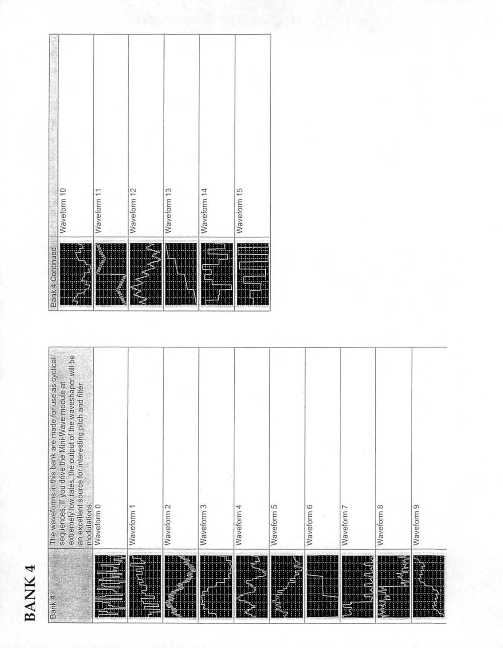
23 MiniWave 22A The MiniWave 22a is a Modcanization of the Wiard/Blacet design. The 22a is a device for outputting waveform samples stored in a digital memory (EEPROM) in response to an analog voltage. Note: see calibration information for optimal use with Modcan Oscillators. Calibrating the Miniwave for Modcan use. There can exist some slight variation in output level between oscillators. For optimal use, select one oscillator to use as the drive signal and calibrate the Miniwave to this signal. Procedure: input a sawtooth waveform from the Osc. 01a. Set input switch to +5V at the bottom of the panel. Set Miniwave to Bank 0, Wave 0. By ear or with a scope, adjust trimpot RT1 on the circuit board for cleanest sine wave (minimal buzzing) Wave Out: Audio or voltage output Input: Audio or voltage input. For typical operation a sawtooth wave is used to drive the Miniwave. When using an 01a Osc set Input select switch to +5V. Use the same position when inputting voltage for quantizing. Set Input select switch to +/-2.5 for sine or triangle and audio signals. Output Sel: Selector switch. Set to NORMAL for all banks except 15. Select Quantize for Bank 15 as the quantizer bank requires a different output level to function correctly. The same is true for any 3rd party quantizer ROMs as well. Bank Indicator LEDs: The Leds indicate the status of the bank selection. A Binary numbering system is used. When LED 1 is on, bank one is selected. LED 1,2, and 4 indicate Bank 7 is selected etc. Simply add the numbers next to the lit LEDs together to get the value. Bank 15 is all Leds on. Bank 0 is all LEDs off. Bank Select: Use to select Banks Bank Select CV AMT: Panel control attenuator and jack for control voltage bank select. Wave Select: Panel control for selection of Waves Each of the 16 banks contains 16 waves for a total of 256. The LED indicators to the left use the same numbering system as the LED Bank indicators. Wave Select CV AMT: Panel control attenuator and jack for control voltage wave select. Prom Select: In the A position the factory EEPROM is selected. B is for the optional EEPROM that can be purchased from 3rd party sources. (See Blacet web site and resources/waveproms/index.html) Input Select: Switch to select the offset suitable for the input signal. Settings for input signals: Sawtooth=+5V Triangle/Sine= +/-2.5V Voltage for quantizing= +5V Audio from external source= +/-2.5V.

24

25
26
27

28
29
30
31
32

33
34

35

36
37 DIODE FILTER 23A The DIODE FILTER 23A is a Low Pass based on the EMS Putney Filter Input to filter Filter output 1 Volt per Octave Input : The filters frequency can track a keyboard or midi>cv converter etc. at this input. Control Voltage input 1 Control Voltage Amount 1: This knob works as an inverting (CCW of zero ) or non-inverting ( CW of zero ) input modulation attenuator. Set to zero for no modulation. Control Voltage input 2 Control Voltage Amount 2: This control is a modulation input attenuator only. Resonance Control Voltage Input Resonance: This knob sets the filter Resonance amount. High settings will cause self oscillation to occur. Resonance CV Amount: Panel attenuator for Resonance CV input. Filter Cutoff : This knob sets the filter cutoff point. The CV inputs add to the frequency set by this control. Gain Control :Use this control to limit the signal that is fed to the filter.

38 Boolean 24A The Boolean module is designed to enhance logic functions within the modular environment. This module is a useful accompaniment for the Sequencer 17a and allows for more interesting and complex clock and gateing control. Essentially the function of the Boolean module is to combine 2 clock signals together and output a variety of different high or low states depending on the inputs condition. An example of this is if you have 2 LFO pulses feeding the 2 inputs of the And Gate section. If one of the LFO s is cycling faster than the other, the output will only pulse when both of the inputs coincide (High + High = High). In other words, if LFO 1 is pulsing at 10 Hz and LFO 2 is 1 Hz then the output will be a 1 second burst of pulses at 10 Hz every other second. As the slow LFO goes high it acts like a switch to allow the input from the second faster LFO to pass to the output. When the slow LFO is low then for as long as it stays that way no pulses are output (Low+ High or Low = Low). See the charts below for the different combinations available: Input un-inverted Inverter: the inverter is used to flip a clock or gate signal so that the output is opposite to the input ie. when the input is high the output is low. Try feeding the origional clock pulse to an envelope gen. and the inverter output to a second envelope. Use the envelopes to control 2 vca s patched to the same source. This produces delay type effects. If the inverter is combined with the other sections, Nand and Nor Gates are possible. Input 1 Input 2 Input 1 Output Output inverted AND GATE Low+Low=Low Low+High=Low High+Low=Low High+High=High OR GATE Low+Low=Low Low+High=High High+Low=High High+High=High Input 2 Output Input 1 XOR GATE Low+Low=Low Low+High=High High+Low=High High+High=Low Input 2 Output Inverter 2: same as above Input Output

39 INTERFACE 25A The INTERFACE 25A is a utility module for converting 1/4 phono jacks to banana jacks and vice versa. This module is useful for patching in external signals and for use with Midi to CV converters.

40 VC Reset LFO 26A The Voltage Controlled Reset LFO 26A is an unusual take on the traditional LFO. The main difference with this design is the capability of resetting the LFO cycle at a point between 10 and 90% of the waveform cycle start point. Triangle Output: +/-2.5V triangle wave output. Sine Output: +/-2.5V sine wave output. Manual Reset: Panel button that when pushed resets the start point of the LFO cycle. The Wave Start pot determines the point at which the waveform resets from (10-90%) CV Start: Control voltage input that works together with the Wave Start control for setting reset start point. CV In: Control voltage input for frequency. The CV AMT attenuates this input. Pulse Width Modulation: This input is for voltage control of the pulse width. The PWM AMT pot is the attenuator for this input. INItial PW: Adjust for Pulse width. Ratios vs Pot position: 0=10:90%, 5=50:50%, 10=90:10% Sawtooth Output: +/-2.5V sawtooth wave output. Pulse Output: 0-5V pulse wave output. This output can be used to gate envelopes etc. Reset Input: Patch a pulse wave to this input to reset the start point of the LFO cycle. Works like Hard Sync on a standard oscillator. Requires an input frequency less than the LFO frequency to work. Wave Start: This is the control that sets the cycle reset point. Frequency CV Amount: A simple attenuator for the CV input. Pulse Width Amount: A simple attenuator for the PWM CV input. Frequency: Panel control for setting the LFO frequency. Range Switch: Panel control setting the range of the LFO between high and low. 1v/Octave input: Use this input for tracking the LFO frequency with a keyboard or midi>cv converter.

41 DUAL MIX 27A The Dual Mix 27A is a utility module for summing and attenuating audio or control voltage. There are two sections with three inputs for each.the top section is more suitable for control voltage mixing, having inverting/non-inverting attenuators and an offset control. The bottom section is more suitable for audio as attenuators have no inversion and complete attenuation is possible. Mix Output : This is the final output for Mix section 1 Mix Inputs: Three inputs that can be mixed together with added offset. Examples of the Mixer s use: 1/ Add several LFO s together to create a complex modulation source. 2/ Offset a 0-5V saw wave to be +/- 2.5V and then invert it. OFFSET Control: The Offset control adds or subtracts voltage from the mixed output by a fixed amount. The range is +/-5 volts. Leave this control at 0 if no offset is required. Level Controls: Attenuates the signal level. Pot rotation CW from 0 will be a non-inverted signal out. CCW from 0 will be an inverted signal out. At 0 there will be full attenuation.

42 CEM LOW PASS 29A The CEM LOW PASS 29A is a 24dB 4 pole low pass filter based on the CEM 3328 filter IC. Most LPF suffer from a 12dB drop in pass band level at high resonance. The CEM 3328 IC has built-in provisions for overriding this limitation. Input to filter Filter output 1 Volt per Octave Input : The filters frequency can track a keyboard or midi>cv converter etc. at this input. Control Voltage input 1 Control Voltage input 2 Resonance Control Voltage Input Resonance AMT : This knob sets the filter Resonance amount. The Res CV input adds to the resonance set by this control. Resonance Compensation Switch: with this switch set to -12dB the filter responds normally at high resonance settings, with typical -12dB attenuation of pass band signal. With the switch in the 0dB position there is no loss in pass band level even at full resonance Control Voltage Amount 1: This knob works as an inverting (turned left of zero ) or noninverting ( right of zero ) input modulation depth control. Set to zero for no modulation. Control Voltage Amount 2: This control is a modulation input attenuator only. Resonance CV Amount: Panel attenuator for Resonance CV input. Filter Cutoff : This knob sets the filter cutoff point. The CV inputs add to the frequency set by this control. Gain Control :Use this control to limit the signal that is fed to the filter.

43 Super Delay 30A Delay Input: Patch in any 5V Pk-Pk source to this input. The Level Pot on lower panel sets the volume of the incoming signal Feedback input: Use this together with the FBK out for external processing of the Regeneration loop Track Switch: Auto-the internal anti-aliasing filter tracks the delay time i.e. longer delaylower frequency. Manual-the Filter panel control (lower right) sets the cutoff. Mix CV input: Control voltage input for wet/dry mix. Regen CV input: Control voltage input for regeneration depth. More regen more repeats Smooth CV : This input is for voltage control of the Regeneration (feedback) amount Delay CV : This input is for voltage control of Delay time. The Delay CV AMT attenuator sets the depth of this input. Level: Panel control for signal input level. If the output sounds distorted use this pot to limit the amount of signal into the delay. Delay Output: This is the main output for patching to VCAs or other modules. Feedback Loop Output: Patch this to Filters, Phaser, or other processing modules with the return signal to the feedback input. Loop Mode Switch: Normal-in this mode the feedback loop is kept internal External-in this position the FBK in and out jacks become active for external loop processing. Dry/Wet Control: This is the control for the Wet/Dry mix. Regeneration CV AMT : A simple attenuator for the Regen CV depth. Delay Time: This is the main panel control for setting delay time. The range 0-10 is 7.5ms-8seconds Delay CV AMT: This is an inverting/ non-inverting attenuator for the delay time cv input. With the pot at +5 the delay time doubles per 1 Volt input. At -5 the delay time is halved per 1 Volt input. This can be used for tracking delay time to pitch. Filter: Control for setting the anti-aliasing filter cutoff. With BBD analogue delays the longer the delay the more aliasing is heard. Usually Delays have a fixed cutoff which limits the usable delay time. With this control the user can override the auto filter setting. Also has interesting sonic potential

44 4VCA 31A The 4VCA 31A is 4 identical VCAs in one single space module. The controls and input/output functions are the same for all four sections. If you have the audio only version then the VCA input will only work with audio and not control voltage. If you have the AC/DC version then the inputs will work with control voltages as well. Warning: with the AC/DC version audio will work but fast envelope times will introduce thumping because of offset. VCA Input : Input for audio signals or control voltage in the case of AC/DC versions. Gain CV Input: Control voltage input for gain control. The CV input is summed together with the level set by the GAIN panel control to the right. Patch Envelope Generators or LFOs etc. to this input for volume contouring. Output: Output for VCA. In the case of the AC/DC version patch this to CV inputs on other modules for control of the control Gain Control: This is the panel Control for gain level added to the cv input to the left. Mix Out : This is a combined output which is a mix of all 4 VCAs

45 X/Y Controller 32A The X/Y Controller 32A is a Joystick interface with numerous panel controls for adjusting the output range and offset. Two switchable modes of operation are fixed internal 5V reference or external input. In external mode the joystick functions as a two axis attenuator for control voltage or audio signal input. Joystick: The vertical axis controls the Y output. The horizontal axis the X. Off or zero position is the lower left corner. Manual Gate: Panel button that when pushed sends a 5V pulse to the gate output. The gate remains high until button is released. Gate Output: Patch this output to envelopes or to reset LFOs etc. X Input: Signal input that is routed to the X output when switch is in the External position. The joystick attenuates this input. Y Input: Signal input that is routed to the Y output when switch is in the External position. The joystick attenuates this input. X Output: Output for X axis. Y Output: Output for the Y Axis. X Mode Switch: Internal uses the on board +5V reference voltage. External routes the X IN to the X OUT with joystick as attenuator. Y Mode Switch: Internal uses the on board +5V reference voltage. External routes the Y IN to the Y OUT with joystick as attenuator. X Amount: Panel control for setting the range of the x axis Y Amount: Panel control for setting the range of the Y axis. X Offset: Adds +/- voltage offset to the x axis. Y Offset: Adds +/- voltage offset to the Y axis.

46 Quadraphonic 33A NW Output: Banana output for the NW channel. Identical signal path as the NW 1/4 output at the bottom of the panel. SW Output: Banana output for the SW channel. Identical signal path as the SW 1/4 output at the bottom of the panel. Main Input: Patch a monophonic audio input to the banana input or the 1/4 jack. Only one is available at a time. NE Output: Banana output for the NE channel. Identical signal path as the NE 1/4 output at the bottom of the panel. SE Output: Banana output for the SE channel. Identical signal path as the SE 1/4 output at the bottom of the panel. E-W Pan CV Input: Control voltage input for left/right (East/West) pan position. E-W Panel Control: Adjust for left/right (East/West) pan position. N-S Pan CV Input: Control voltage input for front/back (North/South) pan position. E-W Panel Control: Adjust for left/right (East/West) pan position. VCA CV input: Voltage control input is for the final output VCA VCA Control: Panel control for final output VCA NW Output: See above NE Output: See above SW Output: See above SE Output: See above

47 Vector Fade 34A Joystick: The joystick controls the mix of the four inputs below. The X and Y axis correspond with the placement of the input jacks. With the joystick in the position shown the upper right jack input signal would be the loudest, with the other three inputs attenuated. X-X FADE CV and Panel Control: Panel pot and control voltage input for the X axis cross fade. Y-Y FADE CV and Panel Control: Panel pot and control voltage input for the Y axis cross fade. VCA CV and Panel Control: Panel pot and control voltage input for global gain control. Main Outputs: Banana and 1/4 output for connection to other modules or as a main out to amplifier or mixer Vector inputs: See above

48 Spring Reverb 35A The Spring Reverb 35A module has two sections. The top section is a circuit that drives an Accutronics 3 spring long tank and then recovers the very low level tank output and amplifies it by a gain factor of 500 to a modular synthesizer level. The bottom section is a simple utility dual passive attenuator offered to maximize panel space. Reverb Input : Reverb input Mix Output: Reverb output that combines both the wet (reverb) signal with the original signal. Mix CV Input : Control Voltage input for external control of wet/dry reverb mix. Wet Output : This output is reverb only signal. This allows reverb mixing or processing to be done by other modules down line. Attenuator Output 1: Output for simple passive utility attenuator. Input 1: Input for attenuating signals or control voltages for modules that don t have on board cv attenuators Level: Panel control attenuator for setting the amount of input signal. If the level of the incoming signal is too high there is a possibility for distortion. DRY/WET Mix: Pot for setting the depth of reverb effect. The Mix CV input adds or subtracts form this control. Feedback: The setting of this knob controls the amount of signal fed back into the reverb tank loop. Medium settings can extend the reverb decay time Attenuator Output 2: Output for simple passive utility attenuator. Input 2: Input for attenuating signals or control voltages for modules that don t have on board cv attenuators Amount 1: Control for setting the amount of attenuation. Amount 2: Control for setting the amount of attenuation.

49 4075 Low Pass 36A The 4075 Low-pass is a faithful reproduction of the Arp 4075 Filter sub modules found in many of the Odyssey and 2600 series synthesizers. The filter module is split into two sections. The top section is the filter and the lower section is an Attenuator. The Attenuator sections intended use is, patched between an output and an input to limit the depth of control voltages for modulation etc. Filter Section Input to filter Filter output Control Voltage input 1 Control Voltage Amount 1: Inverting/non-inverting CV attenuator. Zero for no modulation. Control Voltage input 2 1 Volt per Octave Input : This input can be used to enable the filter frequency to track a keyboard or pitch cv input etc. Resonance Control Attenuator Section Control Voltage Amount 2: Simple attenuator only. No inversion Initial Filter Frequency Control : This knob sets the filter cutoff frequency. The CV inputs add to the frequency set by this control. Gain Control :Use this control to set the input signal level. Reduce if clipping or harshness occurs Attenuator Output :The Attenuator is used to limit the amount of signal or voltage sent between an output and input. Use to control the depth of modulation where there is no depth control on a modules input i.e. the cv input on the LFO module. Input Depth Control

50 Dual Envelope 37A The Dual Envelope module features 2 electrically separate ADSR envelope generators. The intention of this module is to provide the functions of a simpler envelope design than the Envelope Generator 04A in a space saving dual package. Ideal uses for the 37A include: volume contouring of VCAs and Filter frequency control etc. The module is split down the middle. The controls on the left are the same as the ones on the right. Status LED: Indicates the status of the contour voltage at the output Envelope Out: Patch to CV inputs and control points etc. Output voltage is typically 0-5V. Gate Input: Input for a gate signal from Midi>CV, LFO, Osc etc. Requires at least +3V input. Attack: This knob sets the Attack portion of the envelope Decay:This knob sets the Decay portion of the envelope Sustain Release Range: Sets the base time of the envelope. Long is best suited for slow moving envelopes.
51 VC Flanger 38A The VC Flanger is a true analogue Bucket Brigade design. Ultra wide sweep range, voltage controlled Regen, Frequency and on board LFO rate, put the 38A steps above the typical guitar pedal effect. 1V/Octave tracking available for use in controlled feed-back physical modelling patches. Input to Flanger Peak or Notch selector switch Internal LFO output Flanger output: Delayed and Dry signals are mixed equally and output for typical Flange effect. Delay only output: This is the delayed only signal output. Permits the user to mix the delayed/ dry signal externally for greater flexibility. Input Level: Attenuates the input level to reduce clipping LFO Depth: Depth CV input and Panel control for setting the peak amplitude of the on-board Flanger frequency modulation LFO. LFO is also available for external use at the LFO output. Range 0-5V Rate :Rate CV input and Panel control for setting LFO rate. Range 0-5V Regen: Regen CV input and Panel control for adjusting the amount of regeneration or feed back into the Flanger signal path. Will self oscillate at highest settings. Range 0-5V Flange Frequency CV: Control voltage input for modulating the frequency of the Flanger and depth attenuator. Inv/Non-Inverting Flange Frequency: Initial frequency panel control. 1Volt per Octave input: Flanger frequency will track a 1V/Oct keyboard. Useful for analogue physical modelling effects.

52 FREQUENCY SHIFTER 39a A basic definition of the Frequency Shifter process: A Frequency Shifter takes the individual frequency components of the input signal and shifts them by the same number of Hertz, producing a subtle or dramatic effect on the tonal character of the sound. Unlike a Pitch Shifter, the frequency components are translated rather than transposed. Harmonic relationships are not preserved as harmonic overtones become inharmonic partials. Frequency Shifter in use: Small amounts of shift can be used to produce phasing/chorus effects or alien/chipmunk voices. Large shifts will impart a metallic or clangorous quality to the signal. Spectral inversion is possible with large negative shifts. The frequency shifting process generates simultaneous up shifted and downshifted versions of the input signal. Both outputs are available at separate jacks (SUM and DIFF) on the front panel. Shifting through-zero hertz reverses the function of the outputs making up shift become downshift and vice-versa. With both outputs panned left and right unusual stereo image effects are also possible. Shift Control Knob: Rotating the shift knob CW will produce up shifts at the SUM output. Rotating the knob CCW will downshift the signal. Being a thru-zero design the opposite will occur when using the DIFF output. With control at zero the signal will be unaffected. Note: At extreme downshift, output signal frequencies will invert (spectral inversion) High becomes low and low becomes high. Shift range +/-5kHz Quadrature LFO Outputs: 0 and 90 degree sine wave LFO outputs. The rate of the LFO is set by the Shift knob. Can be used with the Quadraphonic or Vector modules to pan the sound in a circular pattern. Depending on settings, shift knob to the right of center will produce CW motion and left of center CCW panning. Input and Level: Main input for the Frequency Shifter. Level Control knob attenuates the signal. CV Input and Attenuator: Control voltage input to modulate the shift frequency. CV amount knob attenuates the incoming voltage. CV range +/-5V 1V per Octave Input: To have the FS track a keyboard, input a 1V/Oct voltage to this input jack. Response Switch: In the up position the FS will have a linear response to CV and shift knob control. This will provide greater shifts near zero position. In Expo mode the shifts will be small near zero. SUM and DIFF outputs: These are the main outputs for the Frequency Shifter. They are opposite to each other in terms of the up shifted and downshifted signal.

53 Dual Multimode 40A The Dual Multimode Filter is a simplified dual version of the 2Pole 12dB Multimode 10A. Two filters in parallel yields some unusual effects that are unobtainable with a single filter. Filter Outputs Filter Inputs Filter Response selector switches CV Inputs Mix Output: Output for the 2 filters in parallel. CV Amount attenuators Resonance Controls Initial Frequency Controls Input Level Controls
54 Fixed Filter 41A The Fixed Filter 41A features 8 bandpass low Q FDNR filters and 2Pole High and Lowpass sections in parralel. Inspired by the Moog Modular Fixed Filter Bank module. The 41A functions like a typical Equalizer except each band is cut only. With all band controls in the fully CW position the filtered signal should closely resemble the source input. Each of the frequency band control knobs turned CCW, removes the indicated frequencies from the source signal. The main function of the Filter Bank is tone shaping but could also be used in front of an envelope follower to alter the amplitude of specific frequencies. A modular compressor with side chain input could be patched together using a combination of the 41A, 45A, 04A, 27A and a few VCAs. Filter Bank Output Filter Bank Output Bypass: true bypass switching for AB comparison with source signal. Input Level Control LPF: Low pass filter removes frequencies below 175Hz HPF: High pass filter removes frequencies above 3kHz

55 6x2 Mixer 43A The 6x2 Mixer is a useful addition to larger modular systems requiring simultaneous envelope contouring and stereo field placement control of multiple signals. The 43As main use function is, mixing and final stage system output for audio. All channel inputs are AC coupled making it unsuitable for voltage processing. The 6x2 Mixer features low noise Class A VCAs with exponential gain response. Panning response curve is logarithmic for minimal -3dB signal loss at centre position. Gain Control Voltage Input: CV input to control the level of the channel VCA Channel Input: signal inputs to be mixed to LEFT and RIGHT main outputs Pan Control Voltage Input: CV input for individual channel pan positioning. Gain Control: Sets the overall gain per channel and doubles as an attenuator for the gain CV input. With no CV present at the GAIN CV input, the gain control will show little effect below the dial 7 indicator position. When CV is applied the knob rotation below 7 will set the range of attenuation for CV voltage effect on the channel. If a smoother curve response is required, apply a fixed +5V voltage to the CV input. Pan Control: Knob positions the channel in the LEFT and RIGHT output mix. Functions in conjunction with the Pan CV input. Master Volume: Controls the overall level of the mix. Works in conjunction with the Master CV input for voltage control of final mix output. Master knob should be at 10 for normal operation. Mainly used as a master fader. LEFT/RIGHT XLR: Standard XLR outputs for connection to LINE level inputs on mixing desk etc. (Clipping can occur on mic input channels unless suitable pad available) 1/4 Balanced Outs: Final mix LEFT/ RIGHT output connection points for standard Tip-Ring-Sleeve (TRS). Balanced stereo type cables should be used to connect to external mixer. Single wire mono cables can be used but the benefits of noise/hum reduction will be lost.
56 904A Lowpass 44A The 904A Lowpass 44A is an electronically accurate recreation of the classic Moog 904A LPF. Some slight enhancements have been included to bring it in line with the Modcan standard interface. The additions are inv/non-inverting CV input, and an additional amplifier stage, for boosting the output level to conform with other Modcan modules. Neither of the additions will colour or detract from the origional sound Input to filter Filter output 1 Volt per Octave Input : Input to be used when filter frequency is to track a keyboard or pitch cv input etc. Control Voltage input 1 Range Selector: Selects the transistor ladder capacitor value that sets the filter frequency sweep range from low, mid, to high. Control Voltage Amount 1: CV inverting/non-inverting input attenuator. Control Voltage input 2 Control Voltage Amount 2: CV input attenuator. Regeneration Control Fixed Voltage: Initial filter frequency panel control. Gain Control :Use this control to limit the signal that is fed to the filter. Lower settings if clipping.

57 E-Follower 45A The E-Follower 4A is divided into three complimentary sections. Envelope Follower section: This is an audio AC to DC voltage converter that tracks the amplitude of an audio signal and outputs a following DC voltage. A built-in Pre-Amp is included for boosting audio. Gate Extractor: Is a comparator with variable peak threshold for extracting a 5V gate pulse from a fluctuating voltage. Ideal for gateing envelope generators or reseting LFOs etc. VC A/R Envelope: This is a simple voltage follower with adjustable Attack/Release times for smoothing the voltage transitions from the envelope follower section or Gate output. Can also be used as a slew limiter with selectable voltage controlled Rise and Fall duration for glide effects with pitch PreAmp output: auxiliary output from the internal pre-amp. Input to PreAmp and Follower Follower output: Voltage output. Patch to any CV input or modulation input. Patch to the VC A/R Envelope to filter jitter and smooth transitions. Gate Extractor Input Gain Factor: Selector switch for setting the gain factor. Select to match level of signal source. 1x for modular levels 10x for line level 100x for direct guitar or mic levels PreAmp Gain Amount Gate Output Status LED: when lit a gate signal is output Envelope input: Input any transitioning voltage or gate signal Attack: Control for setting the attack duration or rise time. Gate Threshold: sets the threshold level the input signal triggers the gate on. Envelope Output Release: Control for setting the release duration or fall time CV Input: use in conjunction with the CV switch to voltage control the duration of the attack or decay or both. Status LED: intensity indicates output voltage level. CV Destination selector: voltage control attack, release or both. CV Amount: Inverting/Non-inverting attenuator scales the incoming CV.

58 Dual Oscillator 46A The Dual Oscillator 46A module is two wide range temperature compensated VCOs in a single space. The 46A uses the same stable VCO core from the Oscillator 01A. Designed to offer the fattened sound of two oscillators with the added convenience of global tuning and switch selectable octave range controls. The UI is optimized for standard keyboard controller use. Referenced tuning controls simplify setup when performing with other concert pitch instruments. While independent use of the Oscillators is possible the normal function mode is to use both oscillators together in unison and de tuned or separated in frequency by a few cents or octaves. With the Fine Tune and De tune controls centered and 0V,1V, 2V...etc input at the 1V/Octave input the oscillators are calibrated to produce a C note at A440Hz. 1 Volt per octave Input: input for tracking the oscillators with a keyboard etc. Applies to both oscillators, A & B. Oscillator A CV input and Attenuator: modulation input for VCO A. Can also be used for approx. 1V/Oct tracking in CW position. Oscillator B CV input and Attenuator: modulation input for VCO A. Can also be used for approx. 1V/Oct tracking in CW position. A and B scaling trim pots: Only adjust if scaling is out of calibration. CW = sharp, CCW = flat Wave Form Selectors: Switch between Saw or Square wave Detune Control: Detunes or offsets the B osc. relative to the A osc. Range is 0 to +/- 1 octave.control taper has been designed so that the greatest change in pitch occurs at the extents of the pots rotation. B Octave Offset: Offsets the B oscillator reletive to the A in Octave intervals. Range 0 to +2 Octaves. The offset can be increased by the detune control and CV inputs. Osc B Out: VCO B auxillary output. Allows independant processing of the B VCO wave forms. Using this output does not remove the signal from the mix output. Pulse Width Modualation: The PWM AMT. control when centered routes the PWM CV to both VCOs.Rotating the knob CW or CCW routes the CV to the indicated VCO only. An external attenuator is needed to control the depth of modulation. PW Control: Sets the initial pulse width of the square wave form of both VCOs Fine Tune Control: Center for standard (A440) tuning. Range Switch: Switches from C at 16.3Hz-523.3Hz in Octaves with 0V at 1V/Octave input. Mix Control: mix level of the two oscillators to the mix output
59 Clock 53A Description: The Clock 53A is an ideal companion to the Sequencer 17A. The 53A can also be used a system clock for triggering logic and EG modules. The unique function of this module is the ability to divide clock pulses using division tables stored in memory. The key function of the Clock module is the ability to divide clock pulses into musically useful divisions of 1/16th, 1/8, 1/4 notes etc. using voltage control. 1/ Clock Tempo: manual control knob for rate or tempo of the internal clock VCO. 2/ Division LED: indicates the status of the divided clock output / Clock LED: indicates the status of the internal clock. 4/ Table indicator LEDs: Uses a binary counting system to indicate table selection. None is 0, 1 and 2 is equal to 3, all lit equals 7. There are 8 tables from 0-7 available. The tables division denominators are listed below. 0/ 1,2,4 1/ 1,2,3,4 2/ 1,2,4,8,16,32,64,128 3/ 1,3 4/ 1,3,6,9 5/ 1,3,6,9,12,16,24,32 6/ 1,2,3,4,6,8,9,12,16,24,32,48,64,96,128 7/ 1,2,3,4,5,6,7,8,9,10,11,12,13,14,15,16 5/ Division Table Selector: Control knob for manual selection of Division table 0-7 6/ Divide by N Selector: Control knob for manual selection of division denominator. An example using table 0: Knob in 1 position will give a division of 1. Clock Out and Div Clk out will be the same. With knob in center position Div Clk out will be half the number of pulses as Clock out for a division of 2. Fully CW will provide a division of 4 or 4 clock pulses equals 1 pulse from the Div Clk out. Using this in a sequence of 1/16/th notes the divide by 2 will be 1/8th note and the divide by 4 will be 1/4 note duration. 7/ Clock Int/Ext Switch: Select between Internal VCO and External clock input. 8/ SYNC Selector: The Sync switch allows the selection of 16 or 32 clock division bar sync. The CLOCK OUT jack becomes an output for pulses that occur every 16 or 32 clock steps to be used to reset a sequencer. This allows the sequencer to reset to a 4/4 bar length regardless of the clock division lengths. In the center position the clock out is not divided. The clock output is the internal clock pulse in this switch position. 9/ Rate CV Input: Control voltage input for internal clock rate. 10/ External Clock Input: Patch the pulse output from a VCO or LFO etc. to this input. Set Clock selector switch to External. 11/ Divide by N CV Input: Input to select the division using a control voltage. See next page diagram for ideas on use. 12/ Table CV Input: Input to select the division table using a CV. 13/ Divided Clock Output: Output of the divided clock 14/ Clock Output: Output of the internal clock VCO or bar sync pulses.
60 Quantizer 55A The Quantizer 55A translates signal voltage from continuous controllers and analogue sequencers into quantized steps conforming to standard musical scales. The two channels function independently of each other but share the same scale and transposition settings. Voltage Input 1 Voltage Input 2 Quantized Output 1 Quantized Output 2 Invert Input 1 Invert Input 2 Scale Selector Transpose Control Scale CV In Transpose CV In Scale LED Indicators Scale Bank Selector Pulse Output 1 Pulse Output 2 Clock Input Clock Select
61 Quantizer 55A panel functions and operation Scale Selector: The scale selector is divided into a16 increments. Each increment selects one of the available scales. The active scale number is indicated in binary format by the panel LEDs. All LEDs off is 0, all LEDs lit is 15. Simply add the numbers next to the LEDs that are lit to get the scale number (See scale list fig.1.). There are 3 banks of scales A,B,C each containing 16 scales for a total of 48. Banks are accessed using the Scale Bank selector switch. The scale selector level is added to the Scale CV input. Transpose Control: The Transpose control knob is divided into 12 semitones. Transposing will retain the scale intervals while shifting the key up or down in semitones. The transpose control level is added to the transpose CV input. In order to transpose or shift the scale without changing the key center, mix an offset voltage with the input signal to be quantized instead. Bank Select Switch: Selects between the 3 banks of scales. See scale list fig.1. Invert: Patching a logic high (+5V) to this input inverts the quantized output. Low voltage in becomes high voltage out and vice versa. Pulse Output: When the input voltage crosses a quantize step boundry a 5 ms pulse is output from this jack. The pulse can be patched to fire envelope generators or any other gate input. This feature is very useful when quantizing continuous voltage controllers like the X/Y Controller or a ribbon controller etc. Try patching a joystick module to the volatge input and patching the quantized output to a VCO 1V/Oct input. Then use the pulse out to fire an envelope controlling a VCA that shapes the VCO output signal. You can generate sequence type patterns this way. Clock Input: The clock input changes the quantizers to function like a sample and hold. Patching a clock or pulse signal from an LFO or VCO etc sets up the quantizer for clocking mode. Regardless of the signal at the voltage input the output will remain static until a clock high pulse is present. When the clock goes high the quantizer will sample the input and then output a quantized voltage. It will then wait for another clock pulse before repeating the sequence of sampling and quantizing. This is a useful feature when you want to use a clock to set a tempo for a sequence of quantized voltages. Try the patch outlined in the pulse out section above with the addition of a clock input to create a sequence of quantized voltages sampled from the joystick but set to a tempo by the clock. Random noise can also be quantized in this way to create random harmonic sequences. Set the Clock in/out switch to in when using the clock input. Bank A Bank C Bank B -Triads 0-1/4 tone 0- Algerian 0- Major 1- Semitone 1- Altered 1- Major6 2- Major 2- Aux Diminished 2- Major7 3- Minor 3- Balinese 3- Maj7b5 4- Dorian 4- Byzantine 4- Minor 5- Phrygian 5- Diatonic 5- Minor6 6- Lydian 6- Spanish 6- Minor7 7- Aeolian 7- Double Harmonic 7- Sus4 8- Mixolydian 8- Hindu 8- Sus2 9- Wholetone 9- Sixtone Symmetric 9- Sus4 Sus2 10- Blues 10- Nine Tone 10- Augmented 11- Diminished 11- Overtone_Dominant 11- Diminished 12- Augmented 12- Pelog 12- Diminished 7th 13- Pentatonic neutral 13- Prometheus 13- Sus7 Sus4 14- Fourths 14- Enigmatic 14- Major 7 b5 15- Octaves 15- Octatonic 15- Major 7 #5

62 CV Recorder 57A The CV Recorder 57A module provides a radical new approach to generating modulation and voltage control signals. The implications for this module are extensive when placed in a modular synthesizer context. Concept: Combine the ability to record and playback control voltage signal events from standard modules with the tools to shape, mix, loop and time scale these performances in a simple and repeatable manner. A Play Mode selection switch Status Tri-LED Record/Trigger Button Loop End Knob Loop Mode Trigger Input Loop Start Knob Record/Playback rate control Reset Input Channel Record Switches 1-4 Record Status LEDs 1-4 Channel Inputs 1-4 Channel Outputs 1-4 Record/Playback Rate CV Loop End CV input Loop Start CV input Gate Output
63 CV Recorder Guide Page 2 Record/Trigger Button: Momentary switch with multiple functions dependingon the status of the Play Mode selection switch next to it. See Chart below for Button functions relative to Play and Loop Mode Switches Forward Bi-Dir Reverse Pressing once plays Pressing once plays Pressing once plays sample forward from sample forward from Loop sample in reverse from One Shot Loop start to loop end start to loop end. Pressing Loop end to loop start as set by panel knobs twice plays in reverse as set by panel knobs Pressing and holding plays Pressing and holding plays Pressing and holding plays the sample forward from the sample forward from the sample in reverse from Hold Play Loop start to loop end Loop start to loop end Loop end to loop start until button is released and then in reverse until button is released until button is released In Loop mode the Rec/Trig Button becomes the record button Press once to activate the rehearse mode (see below for explanation) Press a second time to activate record. Recording is achieved by selecting the input channel Record activation buttons. When the LEDs are lit the channel is selected. The LEDs will extinguish when recording is complete. Loop Play Mode: By default the unit powers up in Play mode. After recording is finished the CV Recorder returns to play mode automatically. There is no switch to select play mode. Placing the PLAY MODE switch in loop mode (middle position) will loop the recording between start and end loop points as set by the corresponding loop knobs. With Play mode switch in the ONE SHOT position, playback will be started when the REC/TRIG button is depressed and released. Pulsing the TRIGGER input jack will do the same. With the switch in lower HOLD PLAY mode holding the REC/TRIG button down will playback the sample for the duration that the button is depressed. The sample will playback according to the LOOP MODE switch settings. Rehearse Mode: While in loop mode depressing the Record Button once places the recorder into rehearse mode. The status LED changes from blinking yellow to green with the loop point indicated by a red blink Rehearse Mode passes the signal at the channel inputs to the channel outputs without recording it. This makes it possible to rehearse the control voltage event without committing it to memory. Once the performance is ready to record simply press the REC button again and start recording. The Status LED will change from green to red during recording and then back to yellow when complete. Be sure to arm the channel first by depressing one or all of the Channel Selector Switches. At the end of recording the channel LEDs will extinguish to prevent accidentally recording over the track. Recording: As mentioned above, select the channels to record before proceeding with the recording. Set the LOOP START and LOOP END knobs to determine where in the track to place the recording Setting the LOOP START fully CCW and LOOP END fully CW provides the longest recording. Shorter recordings are made by placing the loop points closer together. This is also the method for chaining multiple recordings together. Simply record a short segment with loop points set near zero and then move loop points to the end of the first recording and record again. Now place loop start to the beginning and you will hear both recordings one after the other. Duration Control: The Duration control knob and rate CV jack control the sample rate of recording and playback. For most situations, higher sample rates (shorter durations) are best as they provide more samples per second providing a more accurate recording of fast transients and better resolution of slower moving signals. Some experimentation may be required to find the best sample rate/duration for the signal to be recorded. During playback the Duration control can be used to vary the playback speed of the recording. The CV Rate input is 1V/Octave response.
64 CV Recorder Guide Page 3 Channel Record Switches 1-4: Momentary switches select the channel to be recorded. When lit the channel selected will be active in both Record and Rehearse modes. Any combination of switches can be selected. Recording on simultaneous multiple is supported or complex signals can be built up by recording on individual channels one at a time3 etc. Switches can be used to activate PUNCH-IN recording if selected mid-way through a recording. Channel LEDs are turned off when recording is finished to provide both a visual cue and to deactivate the channel to prevent further recording. Channel I/0: Channel inputs are capable of handling signals at +/-5V. Levels outside this range will be clipped To use with 0-10V signals it will be required to offset them prior to recording. The Dual Mixer 27 can be used to scale and offset. Outputs are also +/-5V. Gate Output: The GATE output jack provides a short pulse coincident with the start point of the recording loop. The pulse out can be used to synchronize other logic modules or sequencers etc. with the loop point. Reset Input: Pulsing the reset input with logic high gate will reset the recorded loop to the beginning as set by the LOOP START Knob If Loop mode is set to Reverse it will be from the LOOP END point. Trigger Input: The TRIGGER input jack performs the same functions as the REC/TRIG Button. Pulsing this jack will have the same results in the various modes as outlined in the Record/Trigger Button section. Quick Start Guide: 1/ Patch the output from an X/Y Controller or Sequencer or LFO etc. to Channel One input jack 2/ Patch the output of channel one to the 1V/OCT input on a VCO or Filter etc. 3/ Switch PLAY Mode switch to LOOP position. 4/ Set DURATION control knob to 4 sec. position and turn LOOP START knob fully CCW and LOOP END fully CW 5/ Depress and release Channel One selector switch to ARM channel one as indicated by the CH1 LED 6/ Depress and release REC/TRIG button once to enter REHEARSE mode, checking that input signal is passing to the output jack. The status LED will begin blinking green with one red blink to indicate loop start point. 7/ Once you are satisfied with the modulation signal you are about to record press the REC/TRIG button a second time. Recording will start immediately and continue till the status LED resumes blinking yellow and the Channel LED extinguishes. The recording will immediately playback at the end of record. 8/ Experiment with different loop points and DURATION settings and then try another recording on a different channel. Also try setting new loop points and recording over top of the original recording. Return the Loop knobs to fully left and right to hear all recordings on channel 1 strung together. Experiments: Try recording a sequence from an analogue sequencer on one channel and recording the master clock at the same time on another channel. Then use the clock recording to clock the sequencer and you will have the pitch recording which can be synced to the sequencer to use for modulation. This frees up rows on the sequencer do other things. Also use the clock recording to fire an envelope generator which will now be in sync with the pitch recording. You can also record the output from an envelope generator and a sequencer at the same time. Now you can use the recorded envelope shape to control a VCA etc. This can be really cool if using the BI-DIR setting on the LOOP mode switch. Notice how the envelope changes duration as the playback rate is changed. Try recording the output from an LFO while changing the LFOs frequency or chaining together multiple recordings using different wave outputs from the LFO. This way you can have an LFO that goes from sine to triangle to saw etc. Put a VCA between the LFO and recorder and now record with different levels from the VCA allowing the LFO amplitude to fade in and out. Some of the most interesting effects happen by altering the loop points in odd ways One way to use the loop points is to set for a very short loop and then use an LFO or X/Y Controller to sweep the using the LOOP ST, LOOP END CV input jacks. Patch the same control signal to both jacks and get loop points granular synthesis effects. As you can see there are many possibilities available.
65 VCDO 58A The VCDO 58A is a voltage controlled digital wave form oscillator. Two operator FM is implemented here as is Amplitude modulation (AM) and traditional Exponential FM. There are 16 wave forms selectable with the Wave Control and Wave CV inputs. See the following pages for more details on panel controls and functions. VCDO 58A Quadrature Output 1V/Oct Input Main Output 1V/OCT OUTPUT Exponential FM CV Input Sync Input EXPO CV SYNC IN 7 10 Wave select CV input FM Index CV Input FM Ratio CV Input PWM /AM CV Input Initial Pulse Width/Amplitude Control Range Switch Quantize ON/OFF switch WAVE CV INDEX CV RATIO CV PWM/AM -1-5 PW/AMP HIGH LOW RNGE modcan ON OFF QNT WAVE SEL FM INDEX FM RATIO 4 0 PWM AMT FINE ADJ PITCH Waveform Selector FM Index Control FM Ratio Control PWM/AM CV Amount Fine Tune Control Coarse Tune Control
66 VCDO Guide Waveform Selector Control: Control knob used to select from the 16 on-board waveforms (0-15). All waves are AC +/-2.5V for a 5V peak to peak output. Waveform list 0-Sine 1-Triangle 2-11-sample based waveforms arranged from simple to complex 12-sawtooth 13-PWM pulse 14-PWM double-pulse 15-Noise Initial Pulse Width/Amplitude Control: The Pulse Width/AM control is dual function depending on which of the 16 waves is selected When the Pulse (13) and Double Pulse (14) waves are selected this control in conjunction with the PWM CV jack controls the width of the pulse or square wave shape between 1 and 99% width. When any of the other waves are selected this becomes an amplitude or level control. Setting the knob in the center will produce the lowest level or most attenuation. The AM CV input can be used to control the amplitude like a VCA. The CV input is +/-2.5V so if using with an envelope generator the EG signal needs to be scaled by half to give the full range of control. Modulating this input with a sine wave or other AC signal will produce Amplitude Modulation (AM) effects. FM Index Control: This control in conjunction with the Index CV input, sets the amount or depth of the internal sine wave modulators effect on the carrier wave. Sweep the FM index CV input with an envelope for some classic DX7 type sounds FM Ratio Control: The Ratio Control and ratio CV input tunes the modulator to a rational frequency value relative to the carrier frequency. The modulator and carrier are phase locked which produces beat-free timbres that retain spectral relationships over the entire frequency range. Range Control: The Range control sets the initial frequency of the VCDO. The 1Volt per Octave input jack is summed with this control. The range is 10 octaves from 10kHz-10Hz with the range switch in the HIGH position. In the LOW position the range is 0.040Hz-40Hz. If the Quantize switch is on you can hear the semitone steps as the Range knob is swept. Fine Tune Control: The Fine tune is a fine adjustment for tuning the VCDO. The range available is 1 octave. This control is never quantized regardless of the quantize switch settings Nor is the Expo CV input. Sync Input Jack: The sync input functions identically to the hard sync on a typical VCO. Driving this input with a square wave from another VCO, produces the characteristic hard sync effect. For best results the input sync frequency should be less than the VCO (or VCDO) it is driving. The input pulse is resetting the VCDO wave start with each logic high pulse. This can be useful when the VCDO is functioning as an LFO as the SYNC in can be used to reset or synchronize the LFO start point to a clock or timed event. Main Output: The main output jack is joined by an un-labeled quadrature output jack just next to it on the panel. This second output is a 90 degree out of phase version of the same signal. This feature makes the VCDO into a quadrature oscillator that can be used to do quad panning or quad mixing using the Vector fade module for example. The FM section will also effect the quadrature output. As the FM index is increased the outputs will not remain symmetrical The FM is applied to both waves at the same time and is consequently 90 degrees out of phase as well. The quadrature out is un-labeled as this feature was added after the panels where made. The output signal can become relatively harsh sounding with a complex carrier and high FM index. Judicious filtering with one of the wide variety of Modcan Lowpass filters can go a long way to help tame the output.

67 Digital Delay 59A The Digital Delay is a stereo out DSP signal processor specializing in time delay effects Audio Input Tap Delay Tempo Sync Input Feedback Loop input Feedback Loop Output Filter Selector External Feedback amount Audio Input Level Wet / Dry Mix Regen CV Input Delay Mode/Range Regeneration Delay Time Delay CV Input Delay CV Amount Left Audio Output Right Audio Output Clip and sync indicator
68 Digital Delay panel functions and operation Delay Mode Selector: The mode or range selector sets the delay range. It is impossible to cover the entire delay range with only one range so it was broken down into four ranges of Mono and 4 ranges of ping-pong or stereo delay times. The M is for mono and the S is for stereo. Use the Left output only for mono and both left and right for stereo. In Mono mode the right output is the delay only signal with no mix of dry signal. This makes it possible to mix wet and dry "down-line" using a mixer module if desired. Once a range has been selected the DELAY time knob adjusts the delay time between the upper and lower values for that range. Delay ranges are: 20uS-50mS, 50mS-600mS, 600mS-2.4Sec., 2.4Sec-5.8Sec. Wet/Dry Mix: Sets the wet dry mix of the effect. The Regen CV jack can also be used to CV control the mix. To do this will require an "insert" cable with stereo connector split to 2 mono cables. The Tip is regen CV and the ring is Mix CV. Clip Indicator: Led will lite if the input level is too hot. High Regeneration (feedback) levels will also cause the internal signal to clip if input is high. It is best to allow some headroom for regen when setting initial levels and boost the signal at the amplifier or mixing desk to compensate. LED will also lite in time with a pulse signal at the SYNC input jack. This will show the rate of the sync signal. External Feedback Amount: To use the external feedback loop. Patch the Feedback loop output jack into something like the Frequency Shifter input. Take the FS output and patch back into the external FBK input. The Feedback amount control sets the level of the feedback loop. External feedback only works in MONO mode. Stereo will self oscillate and squeal. Use the Right Audio out for "normal" results but using the Left/Mono out is also possible. The left output will mix some of the dry signal in with the feedback while the right will not. The Mix control also has an effect on the level of feedback signal going to the external module. The best is to experiment with the combination of outputs till you find a sound you like. Tap Temp: Tapping on this button will adjust the delay time to match the time between button depresses. You can use this to tap along with pre recorded music to set a matching Delay time. The Sync input does a similar trick but you can use a clock from a sequencer or LFO to set delay time. Filter Selector Switch: There are two filter modes that can be engaged as part of the delay regeneration loop (not the external FBK) The LP1 is a 2.5kHz Lowpass filter with some resonance. It helps to simulate the slightly dreamy effect one gets with Analogue Delays at higher regen. It does this by progressively filtering the echos as they trail off. Exactly as happens with a BBD. Filter LP2 is a 4kHz LP filter with no resonance used to dull the repeating echos and warm the effect. Center position removes all filtering and returns you to mirror echos with no frequency degradation. Delay CV Control: The Delay time is variable with CV control. Having said that you will find that it responds better to a stepped CV like the output from a sequencer etc. Patching in a low frequency Triangle wave will change the delay time but it is not as successful as one would hope. The reason for this is we had to use cross-fading to eliminate nasty glitches when changing delay times. The result is that slowly transitioning through delay times results in a slight tremolo effect as the signal changes output level. Jump transitions don't suffer from this effect.

69 Quad Envelope 60A The Quad Envelope 60A brings together the traditional functions of the modular Envelope generator with an extended range of features that a micro controller based design can offer. A "paging" interface permits easy access to four individual contour generators programmed by a common set of panel control knobs and switches. All parameters are stored in non-volatile memory without need for battery backup. See following page for more detailed information. Delay Control Attack Control Mode Selector Button Hold Control Decay Control Sustain Control Release Control Channel Indicators Edit Selector CV Amount Control Shape Selector Status Indicators 1-4 Gate Inputs 1-4 Envelope/LFO Outputs 1-4
70 Quad Envelope 60A panel functions and operation fig.1 Overview: The Quad Envelope 60A, as the name suggests, is four envelopes/lfos in one module. Each of the four channels is accessed using the Edit Selection button. Envelope Stage Control knobs are used for dialing in the settings or time constants as with a conventional envelope generator. Once the user is satisfied with the edited settings, holding the Edit Sel button and then momentarily depressing the Shape button, stores the settings to memory. The Delay, Attack, Decay, Sustain GATE and Release stages function identically to the Envelope 04B or Dual EG 47B. The new Hold stage adds an extra punch between the attack and decay stages. See fig.1 for a diagram showing stages. Panel Control Details Edit Selector Button: This button is used to increment through the 4 channels in order that they may be edited by the panel controls. Simply depress the button repeatedly till the desired channels indicator LED is lit.the lit channel is now "live" and all changes made to the panel control knobs and switches will apply to that channel. it is probably wise to save new settings to memory before moving on to edit the next channel as a precaution in case of power disruption, but is not DELAY ATTACK HOLD DECAY SUSTAIN RELEASE essential provided that a save is done before finally shutting down the system. Further editing of the channel will overwrite the buffered or stored settings but will not be permanent till stored. A second function of this button, in conjunction with the Shape button is to store the edits to memory. Saving parameters: Depress and hold the Edit Sel button, while momentarily depressing the Shape button. The channel indicator LEDs will flash 1-4 to show a save has completed. The save function stores settings for all channels to non-volatile memory and is retained even after power down. Mode Selector Button: The mode selector button sets the currently selected channel to function in one of three modes. The LED above the button indicates the mode. Modes settings are saved with the individual channel settings. It is possible to have one of 3 modes for each of the four channels for a possible 12 combinations. LED OFF: Standard Envelope mode. The Delay through Release controls set the time durations of the envelope as shown in fig. 1 above. +5V Gate inputs fire the envelopes when high. LED ON: Gated Envelope Loop mode. The envelope will loop through the Attack, Hold and Decay stages for as long as the gate input is held "high" or on. The Release stage kicks in when the Gate input goes "low" or off. Mostly Triangle shapes are available in this mode so for a more complex envelope shape the output can be used to trigger a second channel set to function in envelope mode. LED Blinking: LFO mode. LFO mode loops through the Delay, Attack, Hold and Decay stages to form a wide variety of wave shapes. With zero Delay, moderate Attack and Decay and zero Hold, Triangle waves are produced. Varying the Attack and Decay will produce rising or falling sawtooth shapes. With equal amounts of Delay and Hold and zero Attack and Decay square waves are possible. The LFO frequency is the sum of the durations of the individual stages. Shorter stage durations will increase the speed of the LFO etc. No gate is required and for this mode and the gate input will be ignored for the channel. fig.2 fig.3 fig.4 Linear Log Expo Shape selector button: The Shape selector button permits the user to select between 3 different envelope curves. The LED above the button indicates the Shape and shape chosen is saved with the individual channel settings. LED OFF: Linear. See fig.2 above for shape. Standard response for use with linear VCAs LED ON: Log. See fig.3. Log can be used to linearize an exponential response VCA LED Blinking: Exponential. See fig.4. Expo can be used to simulate the effect of an audio curve on a linear VCA CV Amount: The CV amount sets the depth of effect the control voltage patched to the CV input jack will have on the envelope. The greater the CV voltage the shorter the duration of the envelope stages. In the case of LFOs, larger CV voltages will increase the frequency of the LFO. This makes it a voltage controlled LFO. CV control has no effect on Sustain. The CV Amount value is stored with the channel. This allows the user to set different CV depths for each of the four envelopes/lfos. Status indicator LEDs: Provide visual feedback of envelope status at each of the 4 channel outputs. Gate Inputs: patching a +5V gate to the GATE INPUTS will trigger the envelope on the corresponding channel. Patching to multiple GATE inputs is allowed and will trigger multiple envelopes as you might expect. It is also possible to patch the output from a channel in LFO mode to the GATE IN of a channel in Envelope mode to have a self triggering envelope.

71 Quad LFO 61A Panel Control Locations Amplitude Control Wave Transform (morph) Control Mode Selector Switch Wave Listing CV Depth Control Edit LFO Selector Store Button LFO Rate Control Channel Wave selector Gate mode selector switch Gate Input LED indicator symbols CV Modulation routing Output polarity selection switch Status Indicators 1-4 Channel CV Inputs 1-4 LFO Channel Outputs 1-4
72 Quad LFO 61A Quickstart Guide This brief outline will get you up and running right out of the box and provide the instant gratification we all need. Step 1: Start by powering up the module with no patch cords connected. You will see the LFO status LEDs do a little dance indicating that the stored knob and switch settings have been loaded from memory into their respective buffers ready for play. Step 2: Patch LFO output 1 to a suitable modulation destination. A good start would be the Expo CV input of a VCO or similar module. This will make it easy to hear the effects of the modulation. Step 3: Set the LFO EDIT knob so that it is aligned with the number one on the dial graphic. This sets LFO 1 as the active LFO ready for editing. Step 4: Set the Wave knob to #4 TRIANGLE, Set Level knob to center position, Transform knob fully CCW, Rate knob can be set to any desired frequency but start with a moderate rate so you can hear the effects of the other controls as they are changed. You will notice that tuning the knobs causes the LFO to jump to the current knob setting. This is intentional but can be modified so that the knob needs to be aligned with the stored settings before the effects of editing will be heard. This is done by powering off the module and then back on while holding the MODE switch down. returning to INSTANT EDIT MODE is done the same way. Step 5: Start by powering up the module with no patch cords connected. You will see the LFO status LEDs do a little dance indicating that the stored knob and switch settings have been loaded from memory into their respective buffers ready for play. Step 6: As you can probably hear you have a Triangle wave modulating the pitch of your VCO about now. sweeping the Transform knob across its range. You will notice the effect of the LFO gradually changing as it morphs between a Triangle wave and a Square wave. The in-between wave shapes are a blend of the two waves as they morph. You can adjust the Level knob to set the desired modulation depth and change the Rate control so try different frequencies. Now try the other waves and the effect that changing the Tranform control has on each one. The Waveform diagrams on the last page will help you to better visualize the Transforms effect on each waveform. Step 7: Staying on LFO 1 for now to keep it simple, try the different polarity setting by incrementing the Polarity Switch. The saved value on first power up is 0-5V+ with LED off. The LED ON setting is +/-5V or double the range with positive and negative swings etc. Step 8: Patch a clock or square wave signal from an LFO or second VCO in low range to the GATE IN jack. Increment the GATE MOD switch till the LED is flashing rapidly. You will notice that the LFO RATE has now changed to the same rate as the external clock or LFO signal. Changing the clock tempo will speed up or slow down the Quad LFOs rate. You could try doing this with the clock also stepping a sequencer so that the LFO is in sync with the sequence events. Step 9: Step the GATE MOD switch one more increment to shut off the SYNC function and remove the clock signal from the GATE IN. Patch that same clock or LFO output into CV INPUT 1. Now adjust the CV Amount knob to hear the effect of modulation on the LFOs RATE. Try a triangle or sine source instead of a clock/square to hear a more gradual transition effect. Turning the CV Amount left of center subtracts while to the right adds to the RATE of LFO 1. You can try selecting the other modulation assignments with the CV MOD switch to hear the effect of modulation on these destinations. To remove the CV effect on each routing set the CV AMOUNT knob to center position to ZERO out the effect. At any point you can hit the STORE button to save any of your edits to memory. I wouldn t do this just yet though as you may want to return to the default settings if you get lost. Powering off and back on will return to the default settings. We have now covered the basic operation of all the knob and most of the switch functions. The next step it to try setting up each of the LFOs as we did in PART I. The key to doing this is remembering to set the LFO EDIT selection knob to the desired LFO to edit before changing the settings. Otherwise you will find yourself editing the wrong LFO channel. You can continue to experiment with the other LFO settings and then continue on to read the rest of this manual for a greater understanding of the other features of the Quad LFO
73 Quad LFO 61A Section 1 Introduction: 1.1 The Quad LFO is the second in a series of modules that represents a new approach in User Interface design for Modcan modules. The intent is to combine multiple iterations of otherwise single module functions, in this case an LFO, into a high density module with large feature set that maximizes panel space and control hardware. As a result many features may not be readily apparent from the front panel alone. The following sections will attempt to help the user grasp the somewhat complex UI and discover that it is both highly versatile and like any other musical instrument, becomes easier to navigate with practice. It is possible to use the Quad LFO in its simplest modes and still get a lot of functionality. There are a LOT of features built into this module, with a few that may require some reading to implement. Again to use the musical instrument example, a little study will be greatly rewarded with a deeper knowledge of the powerful and unique features that lurk within. Basic Concepts 1.2 Each of the 4 LFOs share the same panel control knobs and switches for setting parameters. Each LFO has its own output jack and CV input. The GATE IN jack and its functions are applied to each LFO independently but share the same switch and jack. When first powering up the module the PATCH values for knobs and switches are loaded automatically from internal EEPROM, restoring the unit to a previous state from the last time a STORE was completed. The main control for editing patch settings is the LFO EDIT knob. Placing this knob in any of the four quadrants selects the current LFO for edit. Once the LFO to edit has been selected moving the knobs or toggling switches will override the saved values and become live for the selected LFO. Depressing the STORE button will write the new edit values to memory if desired otherwise can be used as a temporary edit that will not be saved when powered down. The new edited settings are retained in a temporary buffer allowing the LFO EDIT knob to select another LFO for edit and allowing you to return to the previous LFO to edit again later. Parameters do not need to be STORED between edits but may be good practice in the event of a power glitch. Knob edit modes: 1.3 There are two knob edit modes available. They are switched by first powering off the module and then depressing and holding the MODE switch button will powering the module on. This will toggle between the two states. Pressing the STORE button will save the chosen state so that it will be the default state next time the module is powered up. No need to depress the MODE switch after this has been done unless you want to switch to the other knob edit mode. The modes are explained next. Instant Edit Mode: In this mode moving the knobs will cause the knobs value to Jump from the saved value to the new knob position value the instant the knobs are moved. The pros to this are no need to align the knob to the former value stored in memory before editing can occur. Cons are that you can't make a minor tweak to the value easily when switching between LFOs to edit and no visual feedback from knob regarding previously stored values. This is the default factory MODE as it is the one I prefer. Alignment Edit Mode: In this mode the knob is moved till it aligns with the value stored in memory. Moving the knob will not edit the value till it is in approximately in the same position as the last time it was stored to memory. This is also true if switching between LFOs. Editing LFO 1 and then moving the LFO2 and then back to 1 the knobs will need to be re-aligned to continue editing. The main benefit to this style of editing is no sudden jump to a new value, allowing for minor adjustments to stored values. Also it allows the user to seethe knobs previous position when last saved or edited. The sequence of events for editing: 1.4 1/Select LFO to edit using LFO EDIT knob. 2/ Change knob settings and switches for selected LFO. Make sure selected LFO is patched to another module so you can hear the effect of changing parameters. 3/Press STORE button to save edited values or select another LFO for edit and do 1 and 2 above.
74 Quad LFO 61A Section 2 Panel KNOB Definitions: Panel knob settings are assigned to each of the 4 LFOs independently based on EDIT knob position. AMPLITUDE: Knob sets the initial level or peak to peak amplitude of the LFO waveform output in conjunction with the Polarity switch which sets the +/- polarity of the output for each LFO (see below). With Polarity set to +5V the peak to peak output is 0-5V+, when +/-5V the range is 0V to +/-5V, set to -5V the range is 0 to -5V CV AMOUNT: Knob sets the amount or depth of CV modulation between the source CV Channel input jack and the modulation destination. Positioning the knob near center results in 0 modulation depth with fully CW rotation adding positive values and CCW subtracting from values initially set with panel controls. i.e. when modulating amplitude it subtracts or adds to the initial value set by the amplitude control knob. The destinations for modulation are set with CV MOD switch and include, WAVE AMPLITUDE, WAVE TRANSFORM, LFO RATE and WAVEFORM SELECTION. See below for more info on the CV MOD switch. Any or all of the above modulation destinations can be assigned with individual CV AMOUNT settings for each destination. There is only one CV jack per channel so it will be shared by all destinations. If no CV is required for a particular destination just set to center 0 position for off. TRANSFORM: This control has different functions depending on the waveform selected by the WAVE knob. A graphic representation of the waves with their transformed shapes is on last page of this document. For most of the waves the TRANSFORM is like a morph or blend function. It allows two waves to be gradually transformed from one to the other shape. For example, with Triangle wave selected the output is a Tri Wave when Transform control is fully CCW and a square wave when fully CW. The in between settings result in a blend of the two wave shapes dependant on knob position. There are no less than 4096 different wave shapes between these two extremes. The transition will sound more gradual than this number implies however as the increments are small. The WAVES named in the wave list are at the fully CCW position of the TRANSFORM Control knob. The waves at the other end of the MORPH are not named but are depicted in the TRANSFORM graphics on page 4. The CV AMOUNT and CV input can also be used to transform the waves using external CVs. LFO EDIT: The LFO Edit knob selects the target LFO for editing. This is a pot not a switch so there are no click stops to reference. For best results place the knob line indicator pointing directly at the numbers in the dial graphics or at least within the approximate centers of the quadrants indicated. Setting the knob for LFO1 makes that LFO live for editing using the other panel knobs and switches. Switching to LFO2 stops editing in LFO1 and activates LFO2 for edit. The settings made in LFO1 are not lost and can be returned to for further editing by moving the EDIT control back to LFO1 position. Nothing is saved at this point but pressing the STORE button will commit the edits to EEPROM memory and will be reloaded on next power-up. The EEPROM retention spec. is typically 100 years. RATE Control: Pretty simple this one. Adjusts the LFO rate or frequency. Exponential curve response with a 19.1 Octave range of.0008 Hz (1 cycle every 20.8 minutes) to 500Hz. The CV AMOUNT and CV input can also be used to modulate the rate using external CVs. WAVE Control: This knob selects the waveform for each LFO. The numbers, starting at 0 on the dial graphic correspond with the WAVE chart printed on the panel. See page 4 for graphics of waves available. The CV AMOUNT and CV input can also be used for wave selection using external CVs.
75 Quad LFO 61A Section 3 Panel SWITCH Definitions: Panel switch settings are assigned to each of the 4 LFOs independently based on EDIT knob position. The MODE switch is a global assignment and applies to all 4 LFOs, not independently. Depressing the MODE switch while powering on the module is used to set the knob edit mode as discussed in Section 1.3 MODE Switch: This switch sets the operation MODE for the module. Each of the three modes applies globally across all 4 LFOs and can have a dramatic effect on the modules function. Depressing the switch increments through the three modes with LED indicator lit according to state. Mode 1 NORMAL=Mode LED OFF: In this mode the module functions a 4 independant LFOs with EDIT KNOB used to select the LFO to edit. Mode 2 QUADRATURE=Mode LED ON: This mode puts the module into a quadrature state with only settings on channel one applying to all 4 LFOs. Editing the other 3 channels will have no effect. The output waves on channel 1-4 are in quadrature phase with each other. Ch1 = 0 degrees, Ch2 = 90, Ch3 = 180, Ch4 = 270 degrees. See fig.1 for illustration of phases on a sine wave. Quadrature mode is useful when patched with the 4VCA module. Each of the 4 outputs can be patched to the CV inputs of the 4VCA to be used for Quad panning in a quadraphonic speaker system. Patching the 4VCA mix out would give you 4way cross-fading. It can also be used to sequence 4 Envelope generators or a variety of other quad patches. fig.1 fig.2 0d 90d 180d 270d LFO 1 LFO 2 LFO 3 LFO 4 Output 1>2>3>4>1 Mode 3 ROTATE=Mode LED BLINK: This is a unique mode that responds to pulses on the GATE IN jack. The result is that each of the 4 LFOs outputs rotate one jack to the right with each new pulse in. Despite the fact that this is a global MODE each of the 4 LFOs can be edited as in NORMAL mode with all switch, Gate, and knob functions applied to each LFO independently. It is only the ordering of the outputs that are modified in this mode. See fig.2 The Gate pulse controls the rotate stepping but can also be used with the GATE MOD functions simultaneously if selected by the GATE MOD switch. The Output 1-4 Status LEDs do not rotate. This provides some visual feedback if editing the LFOs in this mode. Rotating the LEDs would make it difficult to see what changes are being made by knob edits etc. Store Button: The Store button is used to save edited parameters to memory for future sessions. All knobs and switch states are saved for all of the 4 LFOs. No need to save each LFO separately. A short depress is all that is required. The 4 Output LEDs will sequence 1-4 once to show that a save has been successful. Polarity Switch: This Switch controls the peak to peak voltage of the outputs for each channel. +5V=LED OFF: Output is positive only with peak of 0-5V+ on the selected LFO channel. +/-5V=LED ON: Peak to Peak is +/-5V -5V=LED BLINK: The output swings only negative between -5V and 0 or ground. First select the LFO channel with the EDIT knob, then set the chosen polarity for that channel by incrementing the switch through the 3 states. The LED changes as channel is changed to show polarity setting for each channel.
76 Quad LFO 61A Section 4 Panel SWITCH Definitions continued: CV Modulation Overview. Each of the 4 LFOs has its own CV jack for external modulation control. There are 4 modulation control destinations that can be assigned using the CV MOD switch. Each destination has a separate Depth set by the CV AMOUNT knob. All of the destinations can be assigned or none. Setting the CV AMOUNT knob to center effectively shuts off the modulation to the selected routing. One LFO can modulate another and is a great way to create a complex patch. An LFO can even modulate itself, leading to unpredictable results but it is possible. CV MOD Switch: Use this switch to internally assign the routing or destination of the LFO channel CV input jack This switch has 4 states. Each of the destinations shares one CV input jack. Therefore modulating the frequency and amplitude will be done with the same modulation source. The CV AMOUNT knob sets the level and polarity of modulation for each destination and can be set to differing amounts for each. Rotating the CV AMT right of center adds while left of center subtracts. This helps to compensate for the limitations of sharing one jack for all 4 mod routings. Like all the switches, pressing repeatedly increments the switches state. Modulation Destinations: RATE=MOD LED OFF: In this state the CV input is routed to the LFO RATE. If LFO is at maximum frequency no amount of CV will increase the LFO rate. Only subtracting by setting the CV AMT knob left of center will have any effect. AMP=MOD LED ON: Routes the CV to the AMP(litude) destination. This allows for CV control of output level for each of the LFO channels. This is a great function for changing the depth of vibrato etc. TRANS=MOD LED BLINK: Sends the CV to the TRANSFORM destination. Shape is the function that allows changes to the waveform shapes as discussed in Section 2. WAVE=MOD LED Double BLINK: Fast LED blinking indicates CV routing to the WAVE destination. This allows CV control of waveform selection. GATE MOD Selection Switch: There are 4 different modes for GATE INPUT jack routing. Only one mode is available at any one time but any of the 4 modes can be applied to Each of the 4 LFOs independently. Set to off position on selected LFO for no GATE effect. The LED updates to show GATE MOD selections for each channel as EDIT selector changes channels. NONE=GATE MOD LED OFF: Set to this position if no GATE effect is required RESET= GATE MOD LED ON: In this mode pulses on the GATE IN jack will reset the LFO channel to wave start with each new pulse. This is a good mode if you want to use the LFO wave like an envelope shape to control pitch or filter cutoff etc. HOLD= GATE MOD LED BLINK: Holding the GATE IN Jack high using a square wave or any +5V source voltage will cause the LFO to freeze in position. The LFO will resume once the GATE IN goes low (0V). This can be useful in Quadrature mode as it allows you to freeze panning position or as an effect for modulation. SYNC= GATE MOD LED Double BLINK: This is a very unique mode and one you won t find on any other modular LFO. It allows the use of a clock or second LFO to set the RATE or frequency of the selected channel. This can be very useful for synchronizing the LFO rate with a sequence or other timed events. The Staircase waves are very good in this mode to simulate the effects of an arpeggiator. Try setting all channels to SYNC, then using the ROTATE function for sequenced LFOs synchronized to a clock. Changing the clock speed will alter the rate and sequence tempo in step. The range is 600Hz-0.003Hz and is extremely precise (32bit accuracy)
77 Quad LFO 61A Section 5 I/O Jack definitions: Gate IN: There is only one jack for gate input signals. The GATE MOD destination switch assigns this jack to the various GATE MOD routings that have been previously covered in Section 4. Gate signals are typically 0-5V+ and are usually a square or pulse shape. On this module they can be any shape and between +3V and +10V when high. CV INPUTS: Each LFO has its own CV input jack. These are routed to the various CV modulation destinations by the CV MOD Switch. The maximum input level that will be accepted at these jacks is +/-5V. Positive (0-5V+) and negative (0-5V-) can also be used. LFO Outputs: These are the main outputs for each of the 4 LFOs, The output amplitude can range between 0V and +/-5V depending on the AMP settings in each LFO setup. These outs can be patched back into the LFO CV inputs to enable modulation between LFOs.
78 WAVES WAVE 0 SINE>DOUBLE SINE WAVE 1 CIRCLE>SINE WAVE 2 CURVE L>CURVE R WAVE 3 PEAK(EXPO)>LOG WAVE 4 TRIANGLE>SQUARE WAVE 5 SAW>EXPO WAVE 6 INVSAW>INVEXPO WAVE 7 TRAPAZOID>SLOT WAVE 8 TRI>SLOT WAVE 9 PULSE with PWM WAVE 10 DOUBLE PULSE with PWM WAVE 11 WOBBLE1>WOBBLE2 WAVE 12 STAIR UP 1-16 steps WAVE 13 STAIR UP/DOWN 1-16 steps. WAVE 14 RANDOM STEP with SLEW WAVE 15 COSINE RANDOM>smooth and step =TRANSFORM KNOB CCW =TRANSFORM KNOB CENTER =TRANSFORM KNOB CW
 Wave A CV Input Wave Selector A Osc Wave B CV Input Wave Selector B Osc Detune CV Input Detune 1V/Oct Input Fine Tune Octave Switch Master Tune Quantize")
79 Dual VDO 62A Panel Control Locations Mix Output Oscillator B (separate out) HI-Res Switch Expo CV Input Sync Input Blend CV Input Blend Control (Osc1 & 2 wave mix) Wave A CV Input Wave Selector A Osc Wave B CV Input Wave Selector B Osc Detune CV Input Detune 1V/Oct Input Fine Tune Octave Switch Master Tune Quantize ON/OFF
Quick Start. Overview Blamsoft, Inc. All rights reserved.
 1.0.1 User Manual 2 Quick Start Viking Synth is an Audio Unit Extension Instrument that works as a plug-in inside host apps. To start using Viking Synth, open up your favorite host that supports Audio
mod mo c d an a B Series User Manual
 modcan B Series User Manual Modcan Synthesizer DO s and DON TS Thank you for purchasing Modcan products. Your Synthesizer was built by hand to exacting standards. To get the best long term performance
Q106 Oscillator. Controls and Connectors. Jun 2014
 The Q106 Oscillator is the foundation of any synthesizer providing the basic waveforms used to construct sounds. With a total range of.05hz to 20kHz+, the Q106 operates as a powerful audio oscillator and
VK-1 Viking Synthesizer
 VK-1 Viking Synthesizer 1.0.2 User Manual 2 Overview VK-1 is an emulation of a famous monophonic analog synthesizer. It has three continuously variable wave oscillators, two ladder filters with a Dual
SYSTEM-100 PLUG-OUT Software Synthesizer Owner s Manual
 SYSTEM-100 PLUG-OUT Software Synthesizer Owner s Manual Copyright 2015 ROLAND CORPORATION All rights reserved. No part of this publication may be reproduced in any form without the written permission of
// K3020 // Dual VCO. User Manual. Hardware Version E October 26, 2010 Kilpatrick Audio
 // K3020 // Dual VCO Kilpatrick Audio // K3020 // Dual VCO 2p Introduction The K3200 Dual VCO is a state-of-the-art dual analog voltage controlled oscillator that is both musically and technically superb.
VCA. Voltage Controlled Amplifier.
 VCA Voltage Controlled Amplifier www.tiptopaudio.com Tiptop Audio VCA User Manual The Tiptop Audio VCA is a single-channel variable-slope voltage-controlled amplifier in Eurorack format. It has the following
P9700S Overview. In a P9700S, the 9700K MIDI2CV8 is the power source for the other modules in the kit. A separate power supply is not needed.
 P9700S Overview In a P9700S, the 9700K MIDI2CV8 is the power source for the other modules in the kit. A separate power supply is not needed. The wall-mount transformer for the 9700K is an ac power source
Q179 Envelope++ Q179 Envelope++ Specifications. Mar 20, 2017
 Mar 20, 2017 The Q179 Envelope++ module is a full-featured voltage-controlled envelope generator with many unique features including bizarre curves, a VCA and looping. Special modes offer dual-envelopes
Q107/Q107A State Variable Filter
 Apr 28, 2017 The Q107 is dual-wide, full-featured State Variable filter. The Q107A is a single-wide version without the Notch output and input mixer attenuator. These two models share the same circuit
Q106A Oscillator. Aug The Q106A Oscillator module is a combination of the Q106 Oscillator and the Q141 Aid module, all on a single panel.
 Aug 2017 The Q106A Oscillator module is a combination of the Q106 Oscillator and the Q141 Aid module, all on a single panel. The Q106A Oscillator is the foundation of any synthesizer providing the basic
Analog Synthesizer: Functional Description
 Analog Synthesizer: Functional Description Documentation and Technical Information Nolan Lem (2013) Abstract This analog audio synthesizer consists of a keyboard controller paired with several modules
User Guide V
 XV User Guide V1.10 25-02-2017 Diode Ladder Wave Filter Thank you for purchasing the AJH Synth Sonic XV Eurorack synthesiser module, which like all AJH Synth products, has been designed and handbuilt in
DOEPFER System A-100 Synthesizer Voice A Introduction. Fig. 1: A sketch
 DOEPFER System A-100 Synthesizer Voice A-111-5 1. Introduction Fig. 1: A-111-5 sketch 1 Synthesizer Voice A-111-5 System A-100 DOEPFER Module A-111-5 is a complete monophonic synthesizer module that includes
Semi-modular audio controlled analog synthesizer
 Semi-modular audio controlled analog synthesizer Owner s manual 21.7.2017 - Sonicsmith Hello and thank you for purchasing a Squaver P1 synthesizer! The Squaver P1 is a semi-modular, audio controlled, analog
MMO-3 User Documentation
 MMO-3 User Documentation nozoid.com/mmo-3 1/15 MMO-3 is a digital, semi-modular, monophonic but stereo synthesizer. Built around various types of modulation synthesis, this synthesizer is mostly dedicated
TURN2ON BLACKPOLE STATION POLYPHONIC SYNTHESIZER MANUAL. version device by Turn2on Software
 MANUAL version 1.2.1 device by Turn2on Software http://turn2on.ru Introduction Blackpole Station is a new software polyphonic synthesizer for Reason Propellerhead. Based on 68 waveforms in 3 oscillators
MMO-4 User Documentation
 MMO-4 User Documentation nozoid.com This is a preliminary documentation 1/9 Feature This is the audio path wired inside the synthesizer. Modulation CV are routed to modulation fader in a digital matrix.
PITTSBURGH MODULAR SYSTEM 10.1 and SYNTHESIZER MANUAL AND PATCH GUIDE
 PITTSBURGH MODULAR SYSTEM 10.1 and 10.1+ SYNTHESIZER MANUAL AND PATCH GUIDE 1 Important Instructions PLEASE READ Read Instructions: Please read the System 10.1 Synthesizer manual completely before use
Anyware Instruments MOODULATOR. User s Manual
 Anyware Instruments MOODULATOR User s Manual Version 1.0, September 2015 1 Introduction Congratulations and thank you for purchasing the MOODULATOR compact classic synthesizer! The concept behind this
OCS-2 User Documentation
 OCS-2 User Documentation nozoid.com 1/17 Feature This is the audio path wired inside the synthesizer. The VCOs are oscillators that generates tune The MIX allow to combine this 2 sound sources into 1 The
PULSAR DUAL LFO OPERATION MANUAL
 PULSAR DUAL LFO OPERATION MANUAL The information in this document is subject to change without notice and does not represent a commitment on the part of Propellerhead Software AB. The software described
STO Limited Warranty Installation Overview
 v2.5 2 STO Limited Warranty ----------------------------------------------------3 Installation --------------------------------------------------4 Overview --------------------------------------------------------5
pittsburgh modular synthesizers lifeforms sv-1 user manual v.1
 pittsburgh modular synthesizers lifeforms sv-1 user manual v.1 the heart and soul of modular synthesis The Pittsburgh Modular Synthesizers Lifeforms SV-1 is a complete dual oscillator synthesizer, designed
SNAKEBITE SYNTH. User Manual. Rack Extension for Propellerhead Reason. Version 1.2
 SNAKEBITE SYNTH Rack Extension for Propellerhead Reason User Manual Version 1.2 INTRODUCTION Snakebite is a hybrid digital analog synthesizer with the following features: Triple oscillator with variable
Shifting Inverting Signal Mingler (SISM) from 4ms Company Eurorack Module User Manual
 from 4ms Company Eurorack Module User Manual") Shifting Inverting Signal Mingler (SISM) from 4ms Company Eurorack Module User Manual The Shifting Inverting Signal Mingler (SISM) is a 4-channel voltage manipulator that can scale, invert, attenuate,
Shifting Inverting Signal Mingler (SISM) from 4ms Company Eurorack Module User Manual The Shifting Inverting Signal Mingler (SISM) is a 4-channel voltage manipulator that can scale, invert, attenuate,
EXCLUSIVELY ANALOGUE THE ANALOGUE SYNTHESIZER SPECIALISTS (UNIT 1) 18 THE MEADOWS, CHESTERFIELD, DERBYSHIRE, S42 7JY, ENGLAND
 18 THE MEADOWS, CHESTERFIELD, DERBYSHIRE, S42 7JY, ENGLAND") 1 EXCLUSIVELY ANALOGUE THE ANALOGUE SYNTHESIZER SPECIALISTS (UNIT 1) 18 THE MEADOWS, CHESTERFIELD, DERBYSHIRE, S42 7JY, ENGLAND 01246 272150 INTRODUCTION THE AVIATOR OWNERS MANUAL Welcome to the "AVIATOR"
1 EXCLUSIVELY ANALOGUE THE ANALOGUE SYNTHESIZER SPECIALISTS (UNIT 1) 18 THE MEADOWS, CHESTERFIELD, DERBYSHIRE, S42 7JY, ENGLAND 01246 272150 INTRODUCTION THE AVIATOR OWNERS MANUAL Welcome to the "AVIATOR"
Make Noise Maths V2 Illustrated supplement. by Demonam
 Make Noise Maths V2 Illustrated supplement by Demonam Index 01... Typical Voltage Controlled Triangle Function (Triangle LFO) 02... Typical Voltage Controlled Ramp Function (Saw/ Ramp LFO) 03... Arcade
A-110 VCO. 1. Introduction. doepfer System A VCO A-110. Module A-110 (VCO) is a voltage-controlled oscillator.
 is a voltage-controlled oscillator.") doepfer System A - 100 A-110 1. Introduction SYNC A-110 Module A-110 () is a voltage-controlled oscillator. This s frequency range is about ten octaves. It can produce four waveforms simultaneously: square,
doepfer System A - 100 A-110 1. Introduction SYNC A-110 Module A-110 () is a voltage-controlled oscillator. This s frequency range is about ten octaves. It can produce four waveforms simultaneously: square,
User Guide. Ring Modulator - Dual Sub Bass - Mixer
 sm User Guide Ring Modulator - Dual Sub Bass - Mixer Thank you for purchasing the AJH Synth Ring SM module, which like all AJH Synth Modules, has been designed and handbuilt in the UK from the very highest
Introduction. TUNE Explained:
 Introduction. The TOMS909 is a recreation of Roland's legendary TR-909 analog Tom drums sound generator for use in modular synthesizer format. The TOMS909 includes all the original controls found on the
Galilean Moons. dual amplitude transmutator. USER MANUAL v1.02
 Galilean Moons dual amplitude transmutator USER MANUAL v1.02 Contents Contents... 2 Introduction... 3 Module Features and Specifications... 4 Module Description... 4 Features List... 4 Technical Details...
ZEEON synth User guide
 ZEEON synth User guide version 1.0 BeepStreet 2017 Introduction 2 Application 2 Audio unit 3 Control panel 3 Presets 4 Voice signal flow 4 Oscillators 5 Mixer 5 Filter 6 Envelope generators 6 Low frequency
PITTSBURGH MODULAR FOUNDATION 3.1 and 3.1+ SYNTHESIZER MANUAL AND PATCH GUIDE
 PITTSBURGH MODULAR FOUNDATION 3.1 and 3.1+ SYNTHESIZER MANUAL AND PATCH GUIDE 1 Important Instructions PLEASE READ Read Instructions: Please read the Foundation 3.1 Synthesizer manual completely before
Written by Jered Flickinger Copyright 2017 Future Retro
 Written by Jered Flickinger Copyright 2017 Future Retro www.future-retro.com TABLE OF CONTENTS Page 1 - Overview Page 2 Inputs and Outputs Page 3 Controls Page 4 Modulation Sources Page 5 Parameters Instrument
Tinysizer. Anyware Instruments Tinysizer Analog Modular System
 In the laboratory of the mad Professor Thomas Welsch (a.k.a. Tommy Analog), a baby monster was born. Don t get fooled by its size, as I mentioned: it is a monster! Has a monster sound and monstrous possibilities
HexVCA Manual v1.0. Front Panel. 1 - VCA Offset CV offset, also referred to as bias knob. CV indicator LED. 2 - IN 1-6 The signal input of the VCAs.
 HexVCA Manual v1.0 The HexVCA contains six separate DC coupled logarithmic VCAs that have their outputs normalled to two outputs. The front panel outputs of each VCA is a switching jack which breaks the
Station X/Y. User Manual. Analogue solutions 2010
 Station X/Y User Manual Analogue solutions 2010 Station X/Y Minimodular Synthesisers Introduction We originally introduced a minimodular system of this size back in 2001. It ran for a few years. Now in
Mixer Section. Sample & Hold (S\H) Section MIXER S\H
 Section MIXER S\H") Sample & Hold (S\H) Section Mixer Section S\H S\H IN Selects the parameter that the S&H will "sample" to input the note in the capacitor sequencer. ACCENT The S&H track can be used as an accent track.
Sample & Hold (S\H) Section Mixer Section S\H S\H IN Selects the parameter that the S&H will "sample" to input the note in the capacitor sequencer. ACCENT The S&H track can be used as an accent track.
moddemix: Limited Warranty: Installation:
 moddemix v2.3 1 moddemix: Limited Warranty: ----------------------------------------------------2 Installation: ----------------------------------------------------3 Panel Controls: --------------------------------------------4
semi-mod lar analog synthesizer Operation Man al
 semi-mod lar analog synthesizer Operation Man al Written and produced by Jered Flickinger Copyright 2007 Future Retro Synthesizers TABLE OF CONTENTS 1 Introduction 2. Welcome Overview Power Care Warranty
Please contact with any questions, needs & comments... otherwise go MAKE NOISE.
 DPO Limited WARRANTY: Make Noise warrants this product to be free of defects in materials or construction for a period of one year from the date of manufacture. Malfunction resulting from wrong power supply
NOZORI 84 modules documentation
 NOZORI 84 modules documentation A single piece of paper can be folded into innumerable shapes. In the same way, a single Nozori hardware can morph into multiple modules. Changing functionality is as simple
the blooo VST Software Synthesizer Version by Björn Full Bucket Music
 the blooo VST Software Synthesizer Version 1.0 2010 by Björn Arlt @ Full Bucket Music http://www.fullbucket.de/music VST is a trademark of Steinberg Media Technologies GmbH the blooo Manual Page 2 Table
PHENOL. Introduction. User Manual. Manual Sections. Download a PDF version of the manual here: phenol-manual.pdf
 PHENOL User Manual Download a PDF version of the manual here: phenol-manual.pdf Note that PDF manuals are automatically generated from webpages. Links and embedded media will not be accessible. For the
BoomTschak User s Guide
 BoomTschak User s Guide Audio Damage, Inc. 1 November 2016 The information in this document is subject to change without notice and does not represent a commitment on the part of Audio Damage, Inc. No
Aalto Quickstart version 1.1
 Aalto Quickstart version 1.1 Welcome to Aalto! This quickstart guide assumes that you are familiar with using softsynths in your DAW or other host program of choice. It explains how Aalto's dial objects
I personally hope you enjoy this release and find it to be an inspirational addition to your musical toolkit.
 1 CONTENTS 2 Welcome to COIL...2 2.1 System Requirements...2 3 About COIL...3 3.1 Key Features...3 4 Getting Started...4 4.1 Using Reaktor...4 4.2 Included Files...4 4.3 Opening COIL...4 4.4 Control Help...4
COS. user manual. Advanced subtractive synthesizer with Morph function. 1 AD Modulation Envelope with 9 destinations
 COS Advanced subtractive synthesizer with Morph function user manual 2 multi-wave oscillators with sync, FM 1 AD Modulation Envelope with 9 destinations LCD panel for instant observation of the changed
Q181V Whammy Bar Controller
 This document covers our Whammy Bar controllers in these configurations: Q181V1 Single-axis Whammy Bar in a single-channel Q181 panel Q181V1 Whammy Bar Q182V2 Dual-axis Whammy Bar in a dual-channel Q182
Music Easel Aux Card User s Guide v1.0 by Joel Davel 1/15/2017
 Music Easel Aux Card User s Guide v1.0 by Joel Davel 1/15/2017 Congratulations!!!! The Aux Card is a natural complement to the Easel and way to expand your palette. Introducing the Music Easel Auxilary
Table of Contents: Limited Warranty:
 v 1.0 2 Table of Contents: ----------------------------------------------------2 Limited Warranty: ----------------------------------------------------3 Installation: -------------------------------------------------------------4
Introduction OUT -12V. The Rampage is Befaco s approach to an old invention: the Serge/Buchla ramp generator.
 RAMPAGE USER MANUAL Thanks for your Befaco purchase! Before you plug this module in... 1. Disconnect your cabinet from mains. 2. Triple check the power cord polarity. The colored line on the cable (pin
Mono/Fury. VST Software Synthesizer. Version by Björn Full Bucket Music
 Mono/Fury VST Software Synthesizer Version 1.0 2010-2012 by Björn Arlt @ Full Bucket Music http://www.fullbucket.de/music VST is a trademark of Steinberg Media Technologies GmbH Mono/Poly is a registered
A-108 VCF Introduction. doepfer System A /12/24/48 db Low Pass A-108
 doepfer System A - 100 6/12/24/48 db Low Pass A-108 1. Introduction Level In CV 1 Feedb. BP 6dB A-108 VCF 8 12dB Res. 24dB 48dB Module A-108 is a completely new, unique voltagecontrolled low pass/band
Mixwitch Mixer & Switcher
 Mixwitch Mixer & Switcher Voltage & clock-controlled analog switch with mixer Introduction Focused versatility seems an oxymoron when describing the features that led us to design the Mixwitch. With only
Use the patch browser to load factory patches or save or load your own custom patches.
 1.0.1 User Manual 2 Overview Movement is an eight-stage arbitrary waveform generator that can act as an envelope, LFO, or high-frequency oscillator depending on how it is configured. The interactive graphical
User Reference Manual
 32-33 47th Avenue Long Island City, New York 11101 ph: 718 937 8300 fx: 718 937 9111 www.ehx.com User Reference Manual Manual Notice: This manual is provided as both a guide for instruction, as well as
Atlantis Manual. Atlantis. Dual Oscillator Subtractive Synth Voice. Manual Revision:
 Atlantis Dual Oscillator Subtractive Synth Voice Manual Revision: 2017.09.25 Table of Contents Table of Contents Overview Basic Features Sound Generators Filter Modulators Mixing and Output Installation
FILTER 8 MULTIMODE FILTER/8-PHASE OSCILLATOR CONTENTS INTRODUCTION
 INTRODUCTION Representing the cutting edge in modular analogue voltage controlled filter (VCF) design, Filter 8 offers more possibilities and higher fidelity in 12 HP than ever before. Starting from the
Through-Zero VoltageControlled Oscillator
 Through-Zero VoltageControlled Oscillator Liivatera OÜ Rävala pst. 8, A211 10143 Tallinn Harjumaa Estonia T: +372 637 6441 T: +44 5603 010854 E: contact@liivatera.com Through- Zero VCO Manual 0.1 1 Contents
pittsburgh modular synthesizers microvolt 3900 manual
 pittsburgh modular synthesizers microvolt 3900 manual 2 Thank You! Thank you for purchasing the Microvolt 3900. Your investment in our ideas help support innovative, boutique synthesizer design. Looking
OCTAPAD SPD-30 Effects List
 OCTAPAD SPD-30 Effects List The multi-effects feature 30 different kinds of effects. Number Effect Name 00 THRU 01 SUPER FILTER 02 STEP FILTER 03 FILTER+DRIVE 04 AUTO WAH 05 COMPRESSOR 06 LO-FI COMPRESS
Grendel Drone Commander CLASSIC PEDAL Analog Music Synthesizer. Rare Waves LLC USA rarewaves.net
 CLASSIC PEDAL Analog Music Synthesizer Rare Waves LLC USA rarewaves.net What is it? is a unique synthesizer that delivers thick drone tones with the convenience of an FX pedal stompbox. brings back the
the blooo VST Software Synthesizer Version by Björn Full Bucket Music
 the blooo VST Software Synthesizer Version 1.1 2016 by Björn Arlt @ Full Bucket Music http://www.fullbucket.de/music VST is a trademark of Steinberg Media Technologies GmbH the blooo Manual Page 2 Table
This is the manual for
 This is the manual for by copysomething stuff 2012 document version 1.0 last edited 2013-07-30 1 Table of Contents 1. Intro...3 1.1 Basic description...3 1.2 General design and usage philosophy...4 2 In
Limited WARRANTY: Make Noise implies and accepts no responsibility for harm to person or apparatus caused through operation of this product.
 v2.6 2 DPO Limited Warranty ----------------------------------------------------3 Installation --------------------------------------------------4 Overview ----------------------------------------------------------5
1. GAIN 2. LINE/GTR SWITCH 3. VOLUME (OUPUT) 4. LFO DEPTH 5. OSC/LFO MODE SWITCH 6. TRI/SQR (LFO/OSC WAVEFORM SWITCH) 7. LFO SPEED 8.
 4. LFO DEPTH 5. OSC/LFO MODE SWITCH 6. TRI/SQR (LFO/OSC WAVEFORM SWITCH) 7. LFO SPEED 8.") TRACER CITY MANUAL: Hello, and congratulations on the purchase of a Snazzy FX device! What you have in front of you was designed to provide the widest range of sounds possible, while still being easy enough
TRACER CITY MANUAL: Hello, and congratulations on the purchase of a Snazzy FX device! What you have in front of you was designed to provide the widest range of sounds possible, while still being easy enough
MODEL 9791 HERTZ DONUT OPERATOR S MANUAL. Dual DIgital Oscillator with Internal Modulation Bus
 MODEL 9791 HERTZ DONUT OPERATOR S MANUAL Dual DIgital Oscillator with Internal Modulation Bus THE HARVESTMAN-9791 HERTZ DONUT USER S MANUAL Front Panel Key Introduction Table of Contents Configuration
MKII. Tipt p + + Z3000. FREQUENCY Smart VC-Oscillator PULSE WIDTH PWM PWM FM 1. Linear FM FM 2 FREQUENCY/NOTE/OCTAVE WAVE SHAPER INPUT.
 MKII 1V/ EXT-IN 1 Linear 2 Smart VCOmkII Design - Gur Milstein Special Thanks Matthew Davidson Shawn Cleary Richard Devine Bobby Voso Rene Schmitz Mark Pulver Gene Zumchack Surachai Andreas Schneider MADE
FXDf Limited Warranty: Installation: Expansion:
 v2.3 1 FXDf Limited Warranty:----------------------------------------2 Installation: --------------------------------------------------3 Expansion: ------------------------------------------------------4
Grp Synthesizer A2 Owner s Manual Version 1.4
 Grp Synthesizer A Owner s Manual Version. www.grpsynthesizer.it info@grpsynthesizer.it Grp A Synthesizer Manuale Utente Grp A Synthesizer Manuale Utente CONTENTS Preface Your Instrument Cabinet & rear
Q181RC Ribbon Controller
 The Controller produces a varying voltage as you move your finger along the ribbon strip. Great for pitch bending, playing notes, controlling filter frequency, or other parameters in the synthesizer system.
Lauren Gresko, Elliott Williams, Elaine McVay Final Project Proposal 9. April Analog Synthesizer. Motivation
 Lauren Gresko, Elliott Williams, Elaine McVay 6.101 Final Project Proposal 9. April 2014 Motivation Analog Synthesizer From the birth of popular music, with the invention of the phonograph, to the increased
MATHS Limited Warranty Installation
 v2.6 2 MATHS Limited Warranty ----------------------------------------------------3 Installation ----------------------------------------------------------4 Overview ---------------------------------------------------------5
PHASE28 Phase Shifter [RACK EXTENSION] v. 1.0 MANUAL
![PHASE28 Phase Shifter [RACK EXTENSION] v. 1.0 MANUAL](/thumbs/87/96951608.jpg "PHASE28 Phase Shifter [RACK EXTENSION] v. 1.0 MANUAL") PHASE28 Phase Shifter [RACK EXTENSION] v. 1.0 MANUAL 2018 FX device by Turn2on Software Introducing PHASE28, a new phase shifter effect. The Stages selector gives you control of how many stages from 2
PHASE28 Phase Shifter [RACK EXTENSION] v. 1.0 MANUAL 2018 FX device by Turn2on Software Introducing PHASE28, a new phase shifter effect. The Stages selector gives you control of how many stages from 2
Table of Contents: Limited Warranty:
 v 1.0 2 Table of Contents: ----------------------------------------------------2 Limited Warranty: ----------------------------------------------------3 Installation: ------------------------------------------------------------4
ALM-011. Akemie s Castle. - Operation Manual -
 ALM-011 Akemie s Castle - Operation Manual - (V0.2) Introduction... 3 Technical Specifications 3 Background & Caveats... 4 Core Operation... 5 Panel Layout 5 General Usage 7 Patch Ideas... 13 Tuning Calibration...
SCHLAPPI ENGINEERING A N G L E G R I N D E R MANUAL
 SCHLAPPI ENGEERG GL AN E GRDE M A N UA L R SPECIFICATIONS SCHLAPPI ENGEERG Quadrature Sine Wave VCO / State Variable Filter -with four phase related outputs: 0, 90, 180, 270 -or filter response outputs:
PRODUCT SUPPORT. (516) USER (8737) Fax: (516) Triton Series Products
 USER (8737) Fax: (516) Triton Series Products") PRODUCT SUPPORT (516) 333 - USER (8737) product_support@korgusa.com Fax: (516) 333-9108 Triton Series Products Basic Guidelines for Setting Controller Assignments The Triton Keyboards and Triton Rack feature
PRODUCT SUPPORT (516) 333 - USER (8737) product_support@korgusa.com Fax: (516) 333-9108 Triton Series Products Basic Guidelines for Setting Controller Assignments The Triton Keyboards and Triton Rack feature
TiaR c-x-f synth rev 09. complex X filter synthesizer. A brief user guide
 1 Introduction TiaR c-x-f synth rev 09 complex X filter synthesizer A brief user guide by Thierry Rochebois The cxf synthesizer is a jsfx software synthesizer designed for Reaper. It can be downloaded
APPENDIX. MIDI Controller List. MIDI Controller List
 Some controllers adhere to the normal midi-specified use (eg modwheel, volume) but most are used arbitrarily (and therefore may clash with parameter assignments of other products). We have tried to avoid
RS380 MODULATION CONTROLLER
 RS380 MODULATION CONTROLLER The RS380 is a composite module comprising four separate sub-modules that you can patch together or with other RS Integrator modules to generate and control a wide range of
Welcome to Bengal The semi-modular FM Synthesizer System
 OPERATION MANUAL v.1.0 Welcome to Bengal The semi-modular FM Synthesizer System Thank you for choosing Max for Cats - the new sound is yours! We hope you enjoy using Bengal in your music as much as we
Atlantis Manual. Atlantis. Dual Oscillator Subtractive Synth Voice. Manual Revision:
 Atlantis Dual Oscillator Subtractive Synth Voice Manual Revision: 2018.09.13 Table of Contents Table of Contents Compliance Installation Installing Your Module Overview Basic Features Sound Generators
unicycle Bedienungsanleitung User Guide
 unicycle Bedienungsanleitung User Guide Foreword EN An oscillator is not the only sound source in a synthesizer or modular system, but it is surely the most important one. Because of this, there is a good
Q181EB Expression Block Controller
 The controller produces a voltage as you press the block, similar to the Ondes Martenot and other instruments. Perfect for controlling amplitude as you play notes on the keyboard, to control filter frequency,
HERTZ DONUT MARK III OPERATIONS MANUAL FIRMWARE V1.0
 HERTZ DONUT MARK III OPERATIONS MANUAL FIRMWARE V1.0 FUNDAMENTALS The Hertz Donut Mark III is a complex oscillator utilizing the finest digital sound synthesis techniques from the mid-1980s. It uses a
Manual. Powered by RPCX
 Powered by RPCX Manual WELCOME In the Rob Papen world of synthesis there was one type of synthesizer missing A synthesizer that presents all its controls and features in a single window. The current Rob
Y A B Y A B Y A B Y A B Z X Z X Z X Y A Y A Y A Y A. Mode. Gate. Offset. Scale. Input. Input. Input. Input. Input. Input. Input. Input. Tune.
 -1 Precision dder -2 Four Quadrant Multiplier -3 Full-wave Rectifer -4 Minimum Maximum Has knob recorder 0: smooth or integers Has knob recorder 0: smooth or integers Offset Scale Mode Gate + + - - -5
TABLE OF CONTENTS 1. MAIN PAGE 2. EDIT PAGE 3. LOOP EDIT ADVANCED PAGE 4. FX PAGE - LAYER FX 5. FX PAGE - GLOBAL FX 6. RHYTHM PAGE 7.
 Owner s Manual OWNER S MANUAL 2 TABLE OF CONTENTS 1. MAIN PAGE 2. EDIT PAGE 3. LOOP EDIT ADVANCED PAGE 4. FX PAGE - LAYER FX 5. FX PAGE - GLOBAL FX 6. RHYTHM PAGE 7. ARPEGGIATOR 8. MACROS 9. PRESETS 10.
Dual Digital Build Manual
 Dual Digital Build Manual Introduction This document is meant to aid you in assembling your Dual Digital Oscillator (DDO from now on). Some instructions may be a bit basic for advanced builders but I hope
Many powerful new options were added to the MetaSynth instrument architecture in version 5.0.
 New Instruments Guide - MetaSynth 5.0 Many powerful new options were added to the MetaSynth instrument architecture in version 5.0. New Feature Summary 11 new multiwaves instrument modes. The new modes
DOEPFER System A-100 X-treme Filter A Introduction
 DOEPFER System A-100 X-treme Filter A-106-1 Fig. 1: A-106-1 Controls and In/Outputs 1. Introduction Module A-106-1 is an unique low/high pass filter and has it's origin in our experiments to built a MS20
Owner s Guide. DB-303 Version 1.0 Copyright Pulse Code, Inc. 2009, All Rights Reserved
 Owner s Guide DB-303 Version 1.0 www.pulsecodeinc.com/db-303 Copyright Pulse Code, Inc. 2009, All Rights Reserved INTRODUCTION Thank you for purchasing the DB-303 Digital Bass Line. The DB-303 is a bass
Please contact with any questions, needs & comments... otherwise go MAKE NOISE.
 MATHS Limited WARRANTY: Make Noise warrants this product to be free of defects in materials or construction for a period of two years from the date of manufacture. Malfunction resulting from wrong power
ENSEMBLE String Synthesizer
 ENSEMBLE String Synthesizer by Max for Cats (+ Chorus Ensemble & Ensemble Phaser) Thank you for purchasing the Ensemble Max for Live String Synthesizer. Ensemble was inspired by the string machines from
PowerCore 01 Manual. Manual for PowerCore 01
 PowerCore 01 Manual English Manual for PowerCore 01 SUPPORT AND CONTACT DETAILS TABLE OF CONTENTS TC SUPPORT INTERACTIVE The TC Support Interactive website www.tcsupport.tc is designed as an online support
Plaits. Macro-oscillator
 Plaits Macro-oscillator A B C D E F About Plaits Plaits is a digital voltage-controlled sound source capable of sixteen different synthesis techniques. Plaits reclaims the land between all the fragmented
Manual installation guide v1.2
 Manual installation guide v1.2 Hands up, or we will cross thru zero! I m your Furthrrrr Instant thru-zero linear fm in your Furthrrrr Generator 16-pin DIP IC chip VCO Core replacement that works with any