pittsburgh modular synthesizers microvolt 3900 manual
|
|
|
- Lester Malone
- 5 years ago
- Views:
Transcription

1 pittsburgh modular synthesizers microvolt 3900 manual
2 2
3 Thank You! Thank you for purchasing the Microvolt Your investment in our ideas help support innovative, boutique synthesizer design. Looking back at early monosynths like the ARP 2600 and the Buchla Music Easel, there is a sense of experimentation. The user interface, sound, and functionality of the modern monosynth as defined by the Minimoog and what became the standard subtractive synthesis workflow, had not yet been adopted. Synthesizer design was still fluid and exciting. The Microvolt 3900 recaptures some of this excitement. We focus on this early period of fluid design to create an instrument that does not need to fit the modern monosynth mold; instead it allows us to experiment with new analog circuit designs and synthesis ideas. The Microvolt 3900 is the result of over a year of our efforts and features unique circuitry developed by Michael Johnsen and me to expand the possibilities of analog synthesis. I am very proud of the Microvolt 3900 and what it represents to me. Please use this synthesizer as a laboratory for experimentation and fun. Enjoy, Richard Nicol Founder Product Design Pittsburgh Modular Synthesizers Microvolt 3900 Team Product Design: Richard Nicol Engineering: Michael Johnsen Prototyping: Ross Johnson Fine Tuning: Perry Willig Logistics: Michael Importico Coordination: Danielle Nicol 3

4 Important Information Read Instructions: Please read the Microvolt 3900 manual completely before use and retain for future reference. Only use the DC power adapter provided by Pittsburgh Modular with the Microvolt Using an incorrect power adapter can cause permanent damage to the Microvolt 3900 and the power adapter. The Microvolt 3900 is an electronic device. Exposure to water will cause the Microvolt 3900 circuitry to short circuit and may cause permanent damage. Do not attempt to modify the Microvolt Tampering with the circuitry may cause permanent damage. Do not place heavy objects on the Microvolt The user interface is mounted on a PCB that can be damaged if stressed by excessive weight. Do not attempt to repair the Microvolt Please contact Pittsburgh Modular regarding malfunctions of any kind. Pittsburgh Modular is not responsible for any damage or loss caused by improper use of the Microvolt
5 Table of Contents 1. Microvolt User Interface Map...Page 6 2. Microvolt Patch Bay Map Microvolt 3900 Connections and Signals Interface Conventions Microvolt Patch Examples Page Midi Factory Reset Service and Other Information Warranty Internal Signal Routing Internal Signal Routing Map Individual Synthesis Sections Voltage Controlled Oscillator/Waveform Generator Waveform Mixer Binary Filter Dynamic VCA Output Midi / Arpeggiator Modulation Sources Function Generator Envelope Generator Inverting Mixer / Splitter / Offset.50 5
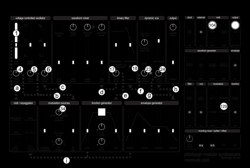
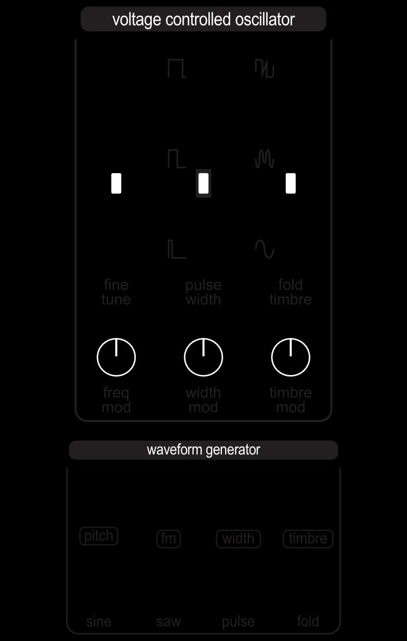
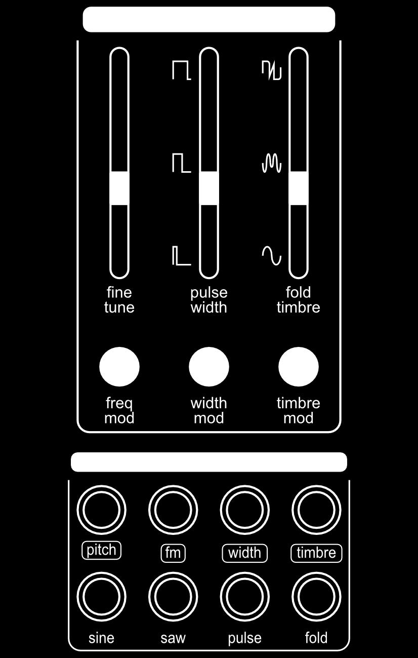
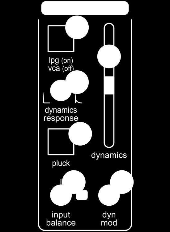
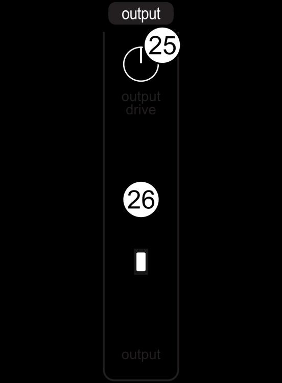
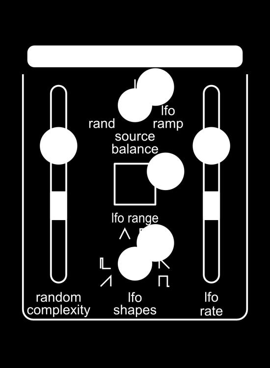
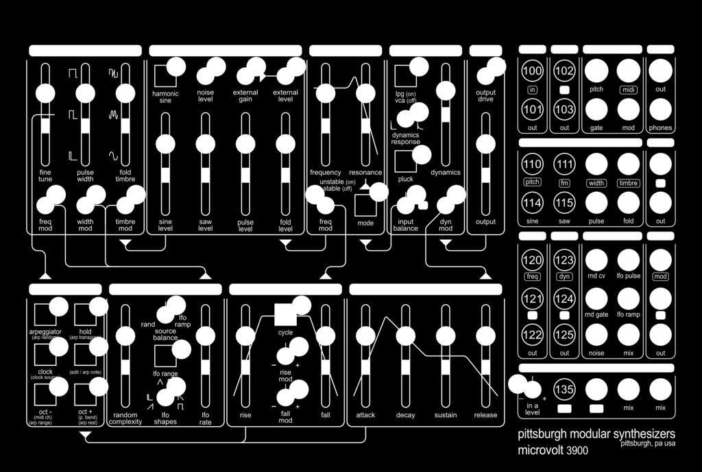
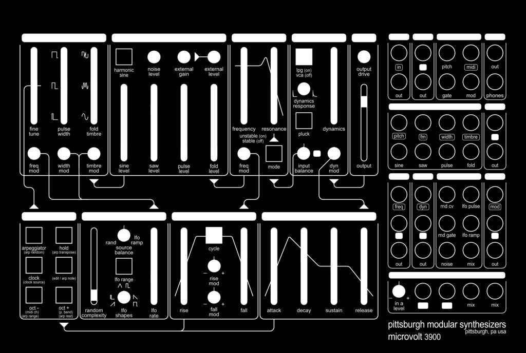
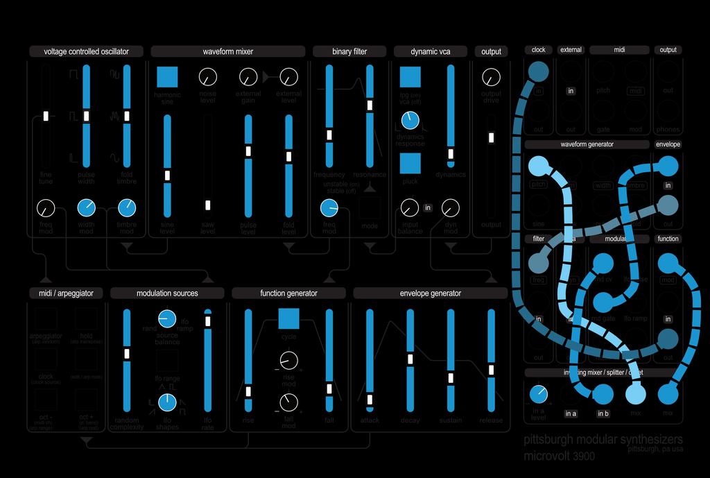
6 1. Microvolt User Interface Map Voltage Controlled Oscillator 1. Fine Tune Slider - Adjust the oscillator pitch. 2. Pulse Width Slider - Set the width of the pulse wave. 3. Fold Timbre Slider - Adjust the depth of the wave folder. 4. Frequency Modulation (FM) Trimmer - Set the FM CV input amount. 5. Pulse Width Trimmer - Set the pulse width CV input amount. 6. Timbre Modulation Trimmer - Set the timbre CV input amount. Waveform Mixer 7. Harmonic Sine Button - Enable/disable harmonic sine wave. 8. Noise Level Trimmer - Set the noise output level. 9. External Drive Trimmer - Set the preamp drive gain. 10. External Level Trimmer - Set the preamp output level. 11. Sine Level Slider - Set the sine wave level. 12. Saw Level Slider - Set the saw wave output level. 13. Pulse Level Slider - Set the pulse wave output level. 14. Fold Level Slider - Set the fold wave output level. Binary Filter 15. Frequency Slider - Adjust the cutoff frequency. 16. Resonance Slider - Adjust the filter resonance amount. 17. Frequency Modulation Trimmer - Set the frequency CV input amount. 18. Mode Button - Enable/disable unstable resonance mode. Dynamic VCA 19. VCA / LPG Button - Switch between VCA and Lowpass Gate mode. 20. Dynamics Slider - Adjust the amount of audio pass-thru. 21. Dynamics Response Trimmer - Set the decay time of the vactrol circuit. 22. Pluck Button - Enable/disable pluck mode. 23. Input Balance Trimmer - Dynamic VCA inputs balance control. 24. Dynamics Modulation Trimmer - Set the dynamics CV input amount. Output 25. Output Drive Trimmer - Set the output drive gain. 26. Output Slider - Adjust the output level. Midi / Arpeggiator 27. Arpeggiator Button - Enable/disable midi arpeggiator mode. 28. Hold Button - Enable/disable note hold mode. 29. Clock Button - Tap tempo clock button. 30. (Edit / Arp Note) Button - Hold to access edit mode functionality. 31. Octave - Button - Shift oscillator pitch down. 32. Octave + Button - Shift oscillator pitch up. Modulation Sources 33. Random Density Slider - Adjust the random constraints. 34. Source Balance Trimmer - Set the modulation output mix. 35. LFO Rate Slider - Adjust the frequency of the LFO. 36. LFO Range Button - Set the frequency range of the LFO. 37. LFO Shapes Trimmer - Set the LFO waveform shapes. Function Generator 38. Rise Slider - Adjust the rise time of the function generator. 39. Cycle Button - Enable/disable cycling of the function generator. 40. Fall Slider - Adjust the fall time of the function generator. 41. Rise Modulation Atteunverting Trimmer - Set the rise CV input amount. 42. Fall Modulation Attenuverting Trimmer - Set the fall CV input amount. Envelope Generator 41. Attack Slider - Adjust the attack time of the envelope generator. 42. Decay Slider - Adjust the decay time of the envelope generator. 43. Sustain Slider - Adjust the sustain time of the envelope generator. 44. Release Slider - Adjust the release time of the envelope generator. 6
7 7
8 8
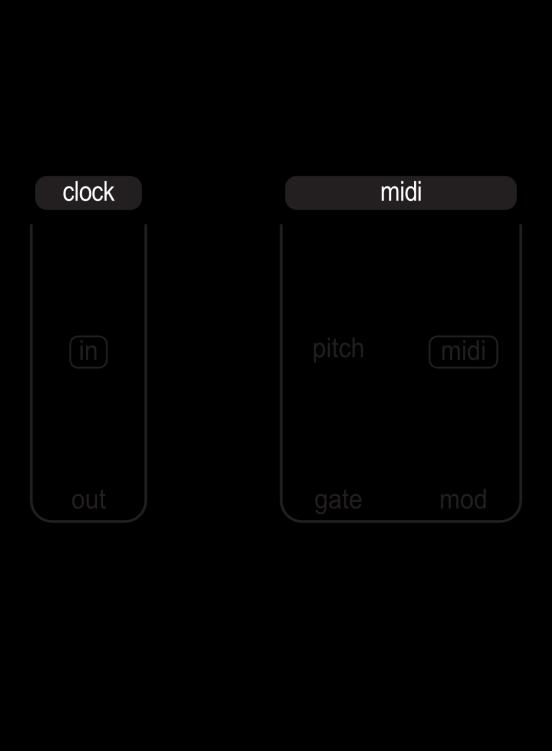
9 2. Microvolt Patch Bay Map Clock 100. Input Jack - Clock signal input Output Jack - Clock signal output (40ms 5v gate signal). External 102. Input Jack - External audio signal input jack Output Jack - Output of preamp circuit. Midi 104. Pitch Output Jack - 1 volt per octave output of midi to cv converter Midi Input Jack - 1/8 stereo midi input jack. Use with included midi cable Gate Output Jack - 5v gate output representing midi note on/off Modulation Output Jack - 0/5v CV signal assignable to midi CC number. Output 108. Output Jack - Mono 1/8 synthesizer output Input Jack - Dual mono 1/8 headphone output. Filter 120. Frequency Input Jack - Frequency modulation CV input Input Jack - Binary filter audio input Output Jack - Binary filter audio output. VCA 123. Dynamics Input Jack - Dynamics modulation CV input Input Jack - Dynamic VCA audio input Output Jack - Dynamic VCA audio output. Modulation 126. Random CV Output Jack - 0/5v Stepped Random CV output Pulse Output Jack - -5v/+5v LFO pulse wave output Random Gate Output Jack - 0/5v Random Gate output Ramp Output Jack - -5v/+5v LFO ramp wave output Noise Output Jack - Post level trimmer noise wave output Mix Output Jack - Modulation sources output. Waveform Generator 110. Pitch Input Jack - 1 volt per octave input used for controlling pitch FM Input Jack - Pitch modulation CV input Width Input Jack - Pulse Width Modulation CV input Timbre Input Jack - Fold wave timbre CV input Sine Output Jack - Post level slider sine wave output Saw Output Jack - Post level slider saw wave output Pulse Output Jack - Post level slider pulse wave output Fold Output Jack - Post level slider fold wave output. Envelope 118. Input Jack - Gate input used to trigger the envelope Output Jack - 0/5v shaped CV signal. Function 132. Modulation Input Jack - Rise/Fall modulation CV input Input Jack - Gate input used to trigger the Function Generator Output Jack - 0/5v shaped CV signal. Inverting Mixer / Splitter / Offset 45. In A Level Attenuverting Trimmer - A input level normaled to +5v In A Input Jack - Audio or CV signal input In B Input Jack - Audio or CV signal input Mix Output Jack - Audio or CV signal mix output Mix Output Jack - Audio or CV signal mix output. 9
10 3. Microvolt 3900 Connections and Signals The Microvolt 3900 is a patchable, analog synthesizer. It combines the functionality of 11 individual synthesizer sections. The sections are internally connected to create a fully functional signal path without the need for patch cables, however 39 patch points are available to connect different synthesizer sections using 1/8 mono patch cables to create custom sounds and textures. The Microvolt 3900 signal path is divided into two basic types of signals: audio signals and control voltages. The audio signal carries the sound that is produced through the synthesizer. The audio signal path starts at the voltage controlled oscillator before passing through other synthesizer sections used to shape the sound such a mixer, filter, and VCA. Audio signal levels vary depending on their location in the signal path. This allows each synthesizer section to have the perfect signal level for the desired sonic results. Detailed information on each section can be found later in the manual. Control voltages (CV) is a static or variable DC or AC voltage used to indirectly manipulate the audio signal by controlling the circuitry that processes the audio. This can be done using a few different types of CV. Gates are represented by a high or low control voltage to create a binary on or off state. A gate can be generated using a pulse or square wave from an oscillator or modulation source, or by using the gate or clock output from the midi module. A gate can be shaped using the function generator or envelope generator to create more complex control voltage (CV) signals. A gate signal or CV signal can be patched to any CV input on the Microvolt 3900 to be used as a modulation source. For example, a CV signal from the output of the function generator patched into the FM input of the oscillator section controls the frequency of oscillator based on the current state of the function generator. Don t forget, audio signals can be used as a control voltage source too. Audio rate modulation is always an interesting world to explore. 10
11 11


12 12
13 4. Interface Conventions The Microvolt 3900 uses several simple labeling conventions to make the user interface and signal flow easy to understand. The labeling is meant as a starting point and not a definitive rule. Experimentation is key. Large white outlines are used to separate individual synthesizer sections such as the voltage controlled oscillator and the waveform mixer. Internal signal paths are shown using an arrow pointing in the direction of the signal followed by a line leading to the signal destination. Most internal signal paths can be rerouted using the patch bay. There are two types of CV trimmers. An attenuator trimmer starts at zero signal when turned full left and at full right it is outputting the full signal level. The zero point for an attenuverter trimmer is at 12 o clock. Turning an attenuverter full left outputs an inverted version of the full signal level and turning an attenuverter full right outputs a non-inverted version of the full signal level. CV input and midi input jacks are labeled using text surrounded by a outline. Audio input and gate input jacks are labeled using text surrounded by a solid background. Output jacks are simply labeled using text. Any output can be patched into any input. Some patching may not result in musical or interesting results but experimentation with the patch points is always encouraged. 13
14 5. Internal Signal Routing The Microvolt 3900 utilizes internal connections to create a fully patched synthesizer voice that does not require patch cables to play. To modify the internal routing or to create something completely new, all of the internal routing can be bypassed using the patch panel. This allows total patching freedom without the constraints of a fixed voiced architecture. Most internal connections are made using switched jacks. A switched jack allows the internal signal path to be cut when a patch cable is inserted. A simple example would be the pitch input of the voltage controlled oscillator. Internally, the pitch output of the midi section is wired to the switched jack input of the voltage controlled oscillator. When a patch cable is plugged into the pitch input of the voltage controlled oscillator, that patch cable breaks the connection to the midi pitch output and replaces it with the signal from the inserted patch cable. The internal signal routing of the Microvolt 3900 is clearly marked on the panel using arrows and lines pointing toward the signal destination. Plugging a patch cable into an internally patched input jack will override any internal patching. 14
15 15
16 16
17 6. Internal Signal Routing Map a. Midi / Arpeggiator Pitch Output Midi pitch and octave shift information sent from the midi Pitch Out (104) to the Pitch Input Jack (110) of the arpeggiator. b. Modulation Sources Output of the modulation Source Balance Trimmer (34) is sent to the oscillator Frequency Modulation Trimmer (4) using FM CV Jack (111), Pulse Width Trimmer (5) using Width CV Jack (112), and Timbre Modulation Trimmer (6) using Timbre CV Jack (113). c. Voltage Controlled Oscillator Waveforms Individual waveform outputs, Sine(114), Saw (115), Pulse (116), and Fold(117) sent to the Waveform Mixer. d. Waveform Mixer Output Output of the Waveform Mixer sent to the input of the Binary Filter(121). e. Function Generator Output Output of the Function Generator(134) sent to the Frequency Modulation Trimmer(17)using Frequency CV Input Jack(120) of the Binary Filter. f. Binary Filter Output Output of the Binary Filter(122) sent to the Input Balance Trimmer(23) using VCA Input Jack(124) of the Dynamic VCA. g. Envelope Generator Output Output of the Envelope Generator(119) is sent to the Dynamic Modulation Trimmer(24) using Dynamic CV Input Jack(123). h. Dynamic VCA Output Output of the Dynamic VCA(125) is sent to the input of the Output section. i. Midi/Arpeggiator Gate Output Midi Gate Output(106) is sent to the Function Generator Gate Input(133) and the Envelope Generator Gate Input(118). 17
18 7. Individual Synthesis Sections The Microvolt 3900 is comprised of 10 individual synthesis sections. Each section has a corresponding set of jacks in the patch bay. The following pages will explain the features of these sections. 18
19 19
20 20
21 8. Voltage Controlled Oscillator / Waveform Generator The voltage controlled oscillator section uses a unique VCA saw core oscillator circuit to generate a full range, temperature stabilized, analog saw wave. Frequency is variable from sub-audio, low frequency oscillator range to ultrasonic allowing the oscillator to function as an audio source or modulation source. The waveform level siders set the output level of the oscillator waveforms. The output of each waveform level slider is patched internally to the input of the binary filter using switched jacks. Patching into any of the individual waveform jacks will remove it from the input of the binary filter. The mixer level slider will still control the output level of the waveform. The oscillator frequency can be modulated using the pitch and FM inputs. The pitch input uses the 1 volt per octave standard for stable pitch tracking. The pitch input is internally patched to the midi pitch output. This allows the octave up(31) and octave down(32) buttons to be used for transposing the oscillator range up and down. The FM input utilizes exponential pitch modulation to create everything from subtle to extreme frequency modulation. Voltage Controlled Oscillator Patching Notes The oscillator does not have a coarse frequency control by default. To add a coarse frequency control, patch the output of the inverting mixer / splitter / offset (137 or 138) into the pitch input (110) of the oscillator. With nothing patched into In A(135) or In B(136), the In A Level(45) trimmer becomes a coarse frequency control by sending 5v to +5v DC into the oscillator core. Patching into the pitch input (110) of the oscillator removes midi pitch(104), octave up(31) and octave down (32) button control. Patching the output of the sine wave(114) into the timbre modulation input(113) creates an interesting waveform. 21
22 9. Waveform Mixer The waveform mixer section combines the output of several distinct audio sources. The harmonic sine button(7) adds subtle wave shaping to the sine wave output. The noise level trimmer(8) adjusts the level of the analog noise circuit. Patching into the noise output jack(130) will remove it from the input of the binary filter. The external gain(9) and external level(10) trimmers work together to control the preamp for processing external or internal signals. The external gain control offers 1x to 30x gain with integrated soft clipping overdrive. Perfect for processing external signals or overdriving internal waveforms. Patching into the external output jack(103) will remove it from the input of the binary filter. The waveform level siders set the output level of the oscillator waveforms. The output of each waveform level slider is patched internally to the input of the binary filter using switched jacks. Patching into any of the individual waveform jacks will remove it from the input of the binary filter. Waveform Mixer Patching Notes The harmonic sine button(7) adds subtle harmonics to the sine wave. This gives the filter resonance something to grab on to for smooth resonated filtering. Adding the sine wave to other waveforms can add additional low end to the sound. Switch the harmonic sine on and off to hear which one sounds the best to beef up the other waveforms. Patch the output of the filter(122) or dynamic vca(125) into the external input (102) then adjust the external gain(9) and external level(10) to beef up or blow out the waveforms. External instruments can be inserted into the Microvolt 3900 signal path using the external input(102). 22
23 23
24 24
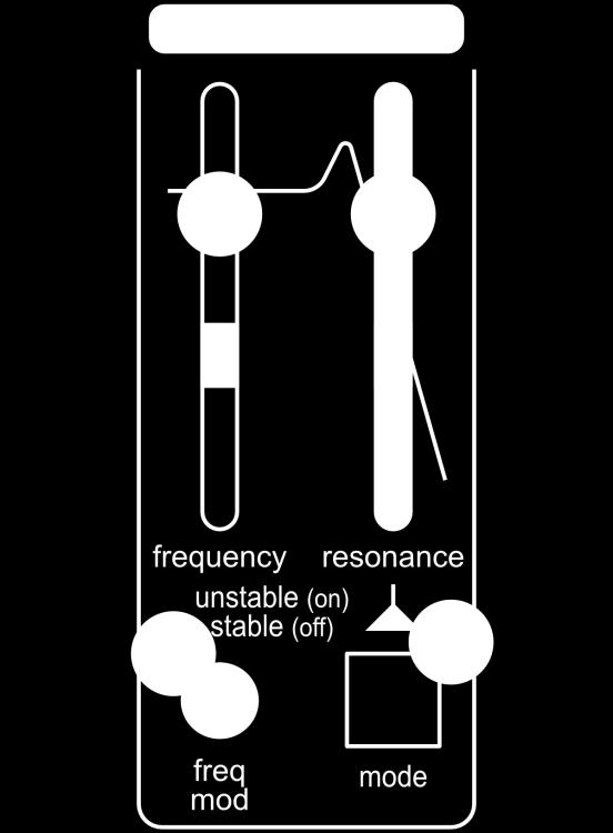
25 10. Binary Filter The binary filter section utilizes the core circuitry of the classic Pittsburgh Modular filter to create a smooth 12db low pass filter. The custom state variable filter topology offers near infinite resonance with or without self oscillation. The signal level going into the filter has a large impact on the resonance and overall sound of the output. The filter utilizes a proprietary soft clipping circuit to add warmth and drive to stronger signals that prevents the filter from creating unwanted distortion. Reducing the level of the incoming waveforms leaves more room for resonance to expand into before hitting the drive circuit. Placing the filter in unstable mode guarantees the signal will drive the soft clipping circuit, adjust the filter frequency(15) and resonance sliders(16) to dial in the perfect amount of overdrive. The frequency slider(15) sets the cutoff frequency of the low pass filter. The resonance slider (16) adjusts the filter Q factor. Patching into the filter frequency input(120) will break the connection with the output of the function generator. Patching into the filter input(121) will break the connection with the output of the waveform mixer. Binary Filter Patching Notes The frequency slider(15) and frequency modulation trimmer(17) work together to control the filter cutoff. When using CV, the frequency slider becomes the offset control and the frequency modulation trimmer controls the amount of CV manipulating the filter cutoff. When you reach the max resonance in stable mode, press the mode button(18) and slide the resonance slider down to extend the amount of resonance available. The filter will begin to self oscillate. Use the inverting mixer / splitter / offset section to mix the output of the function generator(134) with the LFO ramp wave(129). Patch the output(137 or 138) into the frequency modulation input(120) for complex frequency modulation. 25
26 11. Dynamic VCA The dynamic VCA is the heart of the Microvolt An unique processing circuit that adds dimension to the audio waveforms. The basic function of a VCA is to control the loudness of the sound over time. This includes turning a sound on and off or subtly changing the output level. The dynamic VCA is a modern interpretation of Don Buchla s famous lopass gate. The lowpass gate circuit is unique in the way that it simulates the characteristics of natural instruments. When used in lowpass gate mode (19), louder sounds contain more harmonic content and quieter sounds contain less harmonic content. This is not the case when using VCA mode(19). VCA mode simply changes the loudness of the sound without modifying the harmonic content. There is no reason that synthesizers need to simulate how acoustic instruments function but because of how it affects the harmonic content of sound, a lowpass gate sounds more organic or natural compared to a standard VCA. The original lowpass gate was limited to a static response time that varied from unit to unit. This made each lowpass gate a little different. The dynamic VCA in the Microvolt 3900 adds a unique, dynamic response(21) control circuit to the original Buchla lowpass gate concept allowing for customizable gate response times. Dynamic VCA Patching Notes The pluck button(22) bypasses the dynamics modulation trimmer(24) and creates a trigger from any sharp signal sent into the dynamics modulation input(123). This triggers the dynamics response to create an organic percussive strike. The pluck button works best in low pass gate mode(19) and the attack of the envelope generator (41) is set to very short. The input balance trimmer(23) is a mixer. The output of the filter is mixed with a signal patched into the dynamic vca input(124). The input balance trimmer is bypassed if the dynamic vca input is not patched. The dynamics slider(20) and dynamics modulation trimmer(24) work together to control the output level. When using CV, the dynamics slider becomes the offset control and the dynamics modulation trimmer controls the amount of CV manipulating the VCA level. 26
27 27
28 28
29 12. Output The output section conditions the Microvolt 3900 audio signal for a mono line level output(108) and a stereo (dual mono) output(109) for headphones. The output drive trimmer(25) uses our unique soft clipping overdrive circuit to push the audio signal to extremes. The output drive trimmer provides 1x to 30x signal gain designed to press the audio signal up against the soft clipping overdrive circuit. The output fader controls the level for both the line output(108) and headphone output(109) jacks. The output of the dynamic vca is internally wired to the output section. This can not be changed. Output Patching Notes Boosting the output drive will increase the overall and perceived level of the output signal. Reduce the output level fader while adding output drive to ensure the output level remains the same. Not using the headphone output jack(109)? Use a patch cable to patch between the headphone out(109) and the external input (102) to add a feedback loop to the signal patch. 29
30 13. Midi / Arpeggiator The midi / arpeggiator section allows the Microvolt 3900 to respond to digital midi messages from a controller or DAW by converting digital midi data into analog control voltages. In addition to basic midi functionality, this section adds a powerful arpeggiator/note sequencer, tap tempo clock, and pitch octave transpose buttons. Because the feature set of the midi / arpeggiator is deep, this portion of the manual will be split into several sections detailing every feature. Basic Midi Response The Microvolt 3900 responds to midi note on/off, midi note number 0-127, midi clock, midi clock start/stop, midi pitch bend, and midi control change messages. By default, the midi channel of the Microvolt 3900 is set to omni allowing the synthesizer to respond to all midi channels. The midi input jack(105) uses the supplied stereo 1/8 to 5 pin din connector to connect to a traditional 5 pin midi cable. Note pitch(104) is patched internally from the midi section to the pitch input(110) of the voltage controlled oscillator. The midi gate output(106), representing note on/off, is patched internally to trigger the function generator input(133) and the envelope generator input(118). Two Performance Modes The midi section has two performance modes, monophonic and arpeggiator. Monophonic mode converts midi note on/off messages into monophonic 1 volt per octave CV and gate signals that are based on the incoming midi note number and midi on/off messages. The arpeggiator mode creates a repeating sequence of 1 volt per octave CV and gate signals based on the incoming midi notes. 30
31 31
32 32
33 13. Midi / Arpeggiator (continued a) Monophonic Mode Monophonic mode works great when using the Microvolt 3900 as a single voice monosynth. Monophonic mode uses a last note played with retrigger keyboard response to determine note priority. That means the last note played sounds when multiple notes are active and the gate retriggers with every new note played. Monophonic mode outputs a single CV and gate signal based on the active midi note. The midi module features up to 3 note recall when multiple keys are pressed at once. Eurorack standard 1 volt per octave scaled CV is output from the pitch jack(104). The gate output jack(106) outputs a high signal (+5v) when a key is pressed. The gate output jack outputs a low signal (0v) when all the keys are released. Midi Monophonic Mode Patching Notes The pitch output jack(104) can be patched into the function generator modulation input(132) while the function generator is in cycle mode to create a voltage controlled modulation source. The output of the function generator can be used audio rate FM of the voltage controlled oscillator or binary filter. The hold button is a perfect way to create a drone by opening up the dynamic VCA while designing new sounds or exploring various sections of the Microvolt
34 13. Midi / Arpeggiator (continued b) Arpeggiator Mode Arpeggiator mode outputs a single CV and gate signal. Up to 16 note arpeggiations are available when multiple keys are pressed at once or added to the arpeggiator sequence. The arpeggiator offers two key input modes. The first is the standard arpeggiator input method of pressing and holding multiple keys at once. The second method allows notes to be sequenced one at a time, allowing for the insertion of rests and the use of the same note multiple times. The arpeggiator cycles through the selected notes at the rate of the active clock source. The set of selected notes resets when the arpeggiator receives a midi note off message (key released) or the edit key is released(30) when using the sequencing input method. Entering An Arpeggiated Sequence Using Standard Arpeggiator Input Method Enable arpeggiator mode by pressing the arpeggiator button(27). Press and hold keys on a midi keyboard. The arpeggiator will cycle through the depressed keys in the order they were pressed, sometimes called as played. To stop the arpeggiated sequence, release one or all of the depressed keys. Entering An Arpeggiated Sequence Using the Note Sequencing Method Enable arpeggiator mode by pressing the arpeggiator button(27). Press and hold the edit button(30). Press keys on a midi keyboard one at a time to create a sequence of up to 16 steps. Press the octave + button(32) to add a rest. This note sequencing method automatically enables hold mode. To stop the arpeggiated sequence, press the hold button(28). Midi Arpeggiator Mode Patching Notes While an arpeggiated sequence is active, use the octave - button(31) and octave + button(32) to transpose the sequence by octave. Place the function generator in cycle mode(39) and modulate the frequency of the binary filter using the frequency modulation trimmer(17) while an arpeggiated sequence is active. Adjust rise slider(38) and fall slider (40) of the function generator to cycle faster than the rate of the arpeggiated sequence to create a echo type effect. 34
35 35
36 36
37 13. Midi / Arpeggiator (continued c) Additional Arpeggiator Functions The arpeggiator offers 4 additional functions to enhance the active arpeggiated sequence: hold, transpose, random, and arpeggiator range. Hold Function Enable the hold function by pressing the hold button(28). The hold function allows the arpeggiator to cycle through the last set of selected notes after the selected notes have been released, or the edit key is released when using the sequencing input method. Disable the hold function by pressing the hold button. Transpose Function Enable the transpose function by pressing and holding the edit button(30) then pressing the hold button(28). Transpose mode can only be enabled when hold mode is active. The transpose function allows an incoming midi note to transpose the active arpeggiated sequence. The sequence is transposed based on the first note of the arpeggiated sequence. Disable the transpose function by pressing the hold button. Random Function Randomize the arpeggiated sequence by pressing and holding the edit button(30) then pressing the arpeggiator button(27). The random function will random jump between the notes of the arpeggiated sequence. Disable random by pressing and holding the edit button(30) then pressing the arpeggiator button(27). Range Function The range function sets the number of octaves the active arpeggiated sequence will cycle through. The range can be set to 1, 2, or 3 octaves. Set the range by pressing and holding the edit button(30) then pressing the octave - button(31). The first time the octave - button is pressed it will show the active range count. Additional presses of the octave - button will cycle through range options. A range of 1 octave is shown by illuminating the arpeggiator button(27) LED. A range of 2 octaves is shown by illuminating the hold button(28) LED. A range of 3 is shown by illuminating both the arpeggiator button (27) and hold button(28) LEDs. Random Arpeggiation Generator Generate a randomized arpeggiated sequence by pressing the arpeggiator button (27) to enable arpeggiator mode. Next, press and hold the edit button(30) then pressing the holdbutton(28). This will generate a random arpeggiated sequence with a random length (1-16 steps) and random pitch values. 37
38 13. Midi / Arpeggiator (continued d) Three Clock Sources The midi section has 3 clock sources: internal, external midi, and external gate. The clock is used to advance the arpeggiator and the random modulation source. Set the clock source by pressing and holding the edit button(30) then pressing the clock button(29). The first time the clock button is pressed it will show the active clock source. Additional presses of the clock button will cycle through clock source options. Internal clock active is shown by illuminating the arpeggiator button(27) LED. External clock active is shown by illuminating the hold button(28) LED. External gate source is shown by illuminating both the arpeggiator button (27) and hold button(28) LEDs. The clock source is saved in memory and recalled when the Microvolt 3900 is powered on. Internal Clock The internal clock source utilizes the clock button to modify the rate of the internal clock. Tap the clock button(29) to change the tempo of the clock. The internal clock rate is saved in memory and recalled when the Microvolt 3900 is powered on. External Midi Clock The external midi clock responds to midi start/stop messages and midi tempo from an external midi clock source. In external midi clock mode, the clock button(29) acts as a clock divider cycling through 6 available clock divisions. 1, 2, 4, 8, 16, 32. Set the midi clock division by pressing the clock button(29). The first time the clock button is pressed it will show the active clock division. Additional presses of the clock button will cycle through division options. The midi clock division is saved in memory and recalled when the Microvolt 3900 is powered on. External Gate Clock The external gate clock responds to most waveforms that rise above 2.5v. In external gate clock mode, the clock button(29) acts as a clock divider cycling through 6 available clock divisions. 1, 2, 4, 8, 16, 32. Set the external gate clock division by pressing the clock button(29). The first time the clock button is pressed it will show the active clock division. Additional presses of the clock button will cycle through division options. The external gate clock division is saved in memory and recalled when the Microvolt 3900 is powered on. 38
39 39
40 40
41 13. Midi / Arpeggiator (continued e) Additional Midi Settings The midi response can be customized by changing the following settings. The following settings can only be changed when arpeggiator mode is NOT active. Midi CC The midi modulation jack(107) outputs a 0v to 5v DC voltage based on the assigned midi CC number. This jack can be assigned to a midi keyboard mod wheel or any assignable knob. The midi modulation jack can also be assigned to a midi CC number used by a DAW for modulation. To set the active CC number, press and hold the edit button(30). The active midi CC number can only be changed when arpeggiator mode is NOT active. While the edit button is pressed, the midi section assigns the active CC number based on the last incoming CC message it receives. Simply move a mod wheel or turn a knob to assign that midi CC number to the midi modulation output jack. The CC number is saved in memory and recalled when the Microvolt 3900 is powered on. Midi Channel The Microvolt 3900 can be assigned to midi channel 1-16 or omni. To set the midi channel, press and hold the edit button(30). The midi can only be changed when arpeggiator mode is NOT active. The first time the octave - button(31) is pressed it will blink showing the currently selected midi channel. Omni mode is represented with a solid LED. Additional presses of the octave - button will cycle through midi channel numbers. The midi channel is saved in memory and recalled when the Microvolt 3900 is powered on. Pitch Bend There are 4 options for the pitch bend range. 2 semitones (+/- 2 notes), 4 semitones (+/- 4 notes), 8 semitones (+/- 5th), 12 semitones (+/- 1 octave). To set the midi pitch bend range, press and hold the edit button(30). The pitch bend range can only be changed when arpeggiator mode is NOT active. The first time the octave + button (32) is pressed it will blink showing the currently selected pitch bend range. Additional presses of the octave + button will cycle through midi pitch bend options. The midi pitch bend range is saved in memory and recalled when the Microvolt 3900 is powered on. 41
42 14. Modulation Sources The Modulation sources section contains two independent modulation sources, a complex random gate and CV generator, and an LFO with variable wave shapes. The CV output of the random source(126) and the ramp output of the LFO(129) are mixed using the source balance trimmer(34) and output(131) is internally routed to the modulation inputs of the voltage controlled oscillator. Complex Random Generator Inspired by the random source on the Buchla Music Easel, the complex random generator on the Microvolt 3900 is a digitally controlled random source generating both gate and CV signals. The random generator functions similar to an analog, 6 stage shift register. When the clock signal triggers an update and the next register value is loaded, there is a chance it will evolve. Think of it like a 6 step sequencer. The random generator cycles through the 6 steps of the sequence and each time the sequencer jumps to the next step, there is a chance the value stored in that step will be replaced with a new value. The result is a random source that feels both random and evolutionary, with an ever evolving 6 step pattern cycle. The random complexity slider(33) sets both the chance a CV value will change, the range the CV value can change, and also the density of the gates. Both the gate and CV signals have a 0v to 5v range. The complex random generator is triggered by the active clock source selected in the midi / arpeggiator section. To adjust the chance a CV value will change with each step and the density of the random gates use the random complexity slider(33). Moving the slider up will increase the chance a step will update. LFO The LFO is a utility low frequency oscillator with variable ramp and pulse wave outputs. Perfect for long sweeps or audio rate frequency modulation. The LFO range button(36) switches between very slow modulation and audio rate modulation. The LFO shapes trimmer(37) defines the wave shapes of the LFO. It defines the width of the pulse wave and the ramp wave shifts from a ramp, to a triangle, to a saw wave. 42
43 43
44 44
45 15. Modulation Sources (continued) Modulation Sources Patching Notes Use the random gate output jack(128) to trigger the Microvolt 3900 by patching it into the input jack (135) of the inverting mixer / splitter / offset section. Be sure to turn the In A Level Attenuverting Trimmer(45) full right. Patch the first output jack(137) of the inverting mixer / splitter / offset section to the input of the function generator(133) and the second output jack(138) into the input of the envelope generator(118). Use the Random CV output jack as a modulation source for the function generator modulation input(132) to modulate the length of the rise and fall of the function generator. Remember, the random CV output is synced to the arpeggiator clock, that means when using the arpeggiator function, the random will provide a clock synced source of random voltage perfect for wave shape modulation or frequency cutoff modulation. 45
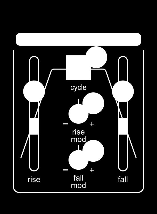
46 16. Function Generator The function generator is a complex dual stage (attack/release) envelope generator with voltage controllable rise (41) and fall(42) times. The cycle button(39) retriggers the function generator at the end of the fall stage to create a voltage controlled low frequency oscillator. When used as a low frequency oscillator, the rise slider(38) sets the length of the rise of the waveform and the fall slider(40) sets the length of the fall of the waveform. The function generator modulation input jack(132) can be used to control the frequency of the LFO. The rise and fall modulation trimmers (41 and 42) can be used to control the symmetry of the modulation. The input of the function generator is internally patched to the output of the midi gate jack(106). If you do not want the midi gate to trigger the function generator, plug a patch cable in the input jack(133) of the function generator to break the internal connection to the midi gate output. The output jack(134) of the function generator is internally patched to the frequency modulation input jack(120) of the binary filter. Function Generator Patching Notes An interesting low-fi filter sound can be created by setting the function generator to cycle as quickly as possible and adjusting the binary filter frequency modulation trimmer(17). Take the sound one step further by patching the midi pitch output jack(104) into the function generator modulation input jack(132) and set the rise modulation and fall modulation trimmers full left. This allows the rate of the rise and fall to change with the midi note. The function generator makes a great voltage controlled LFO for audio rate modulation of the voltage controlled oscillator. 46
47 47

48 48
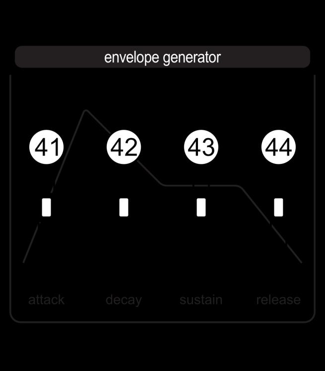
49 17. Envelope Generator The envelope generator section is a four stage (attack, decay, sustain, release) envelope generator that smooths the shape of the incoming gates and triggers to produce a more expressive instrument. The envelope generator output can be used to control the amplitude of an oscillator, the cutoff frequency of a filter or any other function that accepts control voltages. The incoming gate or trigger signal passes through each of the four stages to output an envelope. When the envelope generator module receives a gate or trigger signal, the attack slider(41) determines the amount of time needed for the envelope generator to reach the peak output voltage and move on to the decay stage. The decay slider(42) sets the amount of time needed to transition to the level set by the sustain slider(43). The sustain level is maintained as long as the incoming gate remains on or high. Once the incoming gate goes low or off, the release slider(44) sets the time needed to close the envelope and return the envelope generator output to 0 volts. Envelope Generator Patching Note A classic monosynth sound can be achieved by patching the output jack(119) of the envelope generator into the binary filter frequency modulation input jack (120). This syncs the filter and VCA modulation. Adjust the binary filter frequency modulation trimmer(17) until the shape of the envelope can be heard in the filter sweep. 49
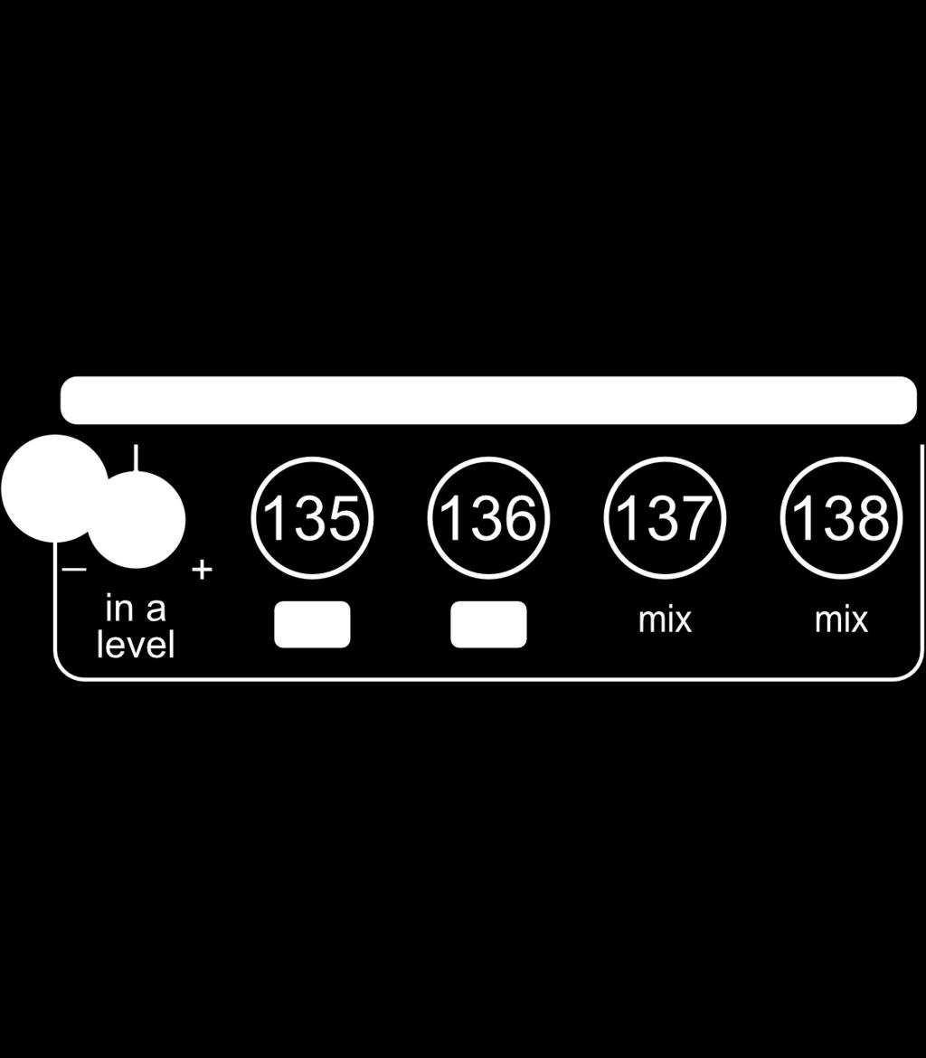
50 18. Inverting Mixer / Splitter / Offset The inverting mixer / splitter / offset section is a standalone audio and CV processing module included to enhance the functionality of the Microvolt 3900 patchbay. Because of the flexible design, the functionality of the section can vary based on the needs of the patch. Section Functions 2 Channel Mixer Patch an audio or CV signal into input a(135) and input b(136) to mix the signals. A copy of the mixed output is available at both output jacks(137 and 138). The level of input a is set using the input a atteunverter trimmer(45). Set to 12 o clock, the attenuverter is in the off position. Turning the trimmer to the right will raise the level of the input a signal up to the level of the incoming signal or unity gain. Turning the trimmer to the left will raise the level of an inverted version of the signal up to the level of the incoming signal or unity gain. Signal Splitter Patch a signal into input a the turn the input a level trimmer(45) full right. A copy of the input signal is available at both output jacks(137 and 138). Signal Inverter Patch a signal into input a the turn the input a level trimmer(45) full left. An inverted copy of the input signal is available at both output jacks(137 and 138). DC CV Source The input a level trimmer(45) is internally patched to a 5v source. The input a level trimmer can be used to attenuate and invert this 5v DC signal. A copy of this voltage is available at both output jacks(137 and 138). Signal Offset The input a level trimmer(45) is internally patched to a 5v source. The input a level trimmer can be used to attenuate and invert this 5v DC signal. Patch an audio or CV signal into input b(136) and the DV voltage from channel a will be added to the signal sent to input b. A copy of mix is available at both output jacks(137 and 138). 50
51 51
52 19. Microvolt Patch Examples This section contains six patch examples that showcase the wide range of functionality and sounds available using only the Microvolt 3900 and a midi keyboard. The patches are designed to familiarize musicians with the layout, synthesis concepts, and sonic potential available within the Microvolt
53 53
54 54
55 19. Microvolt Patch Example 1 Clean Start (Basic Patch) This patch is a clean starting point to begin a new patch. Understanding this patch is the first step toward getting the most out of the Microvolt The important user interface controls are highlighted in blue but all of the controls of the Microvolt 3900 can impact the sound and functionality of the patch. Once the initial patch is set up, experiment with one setting at a time to understand its effect on the signal path. 55
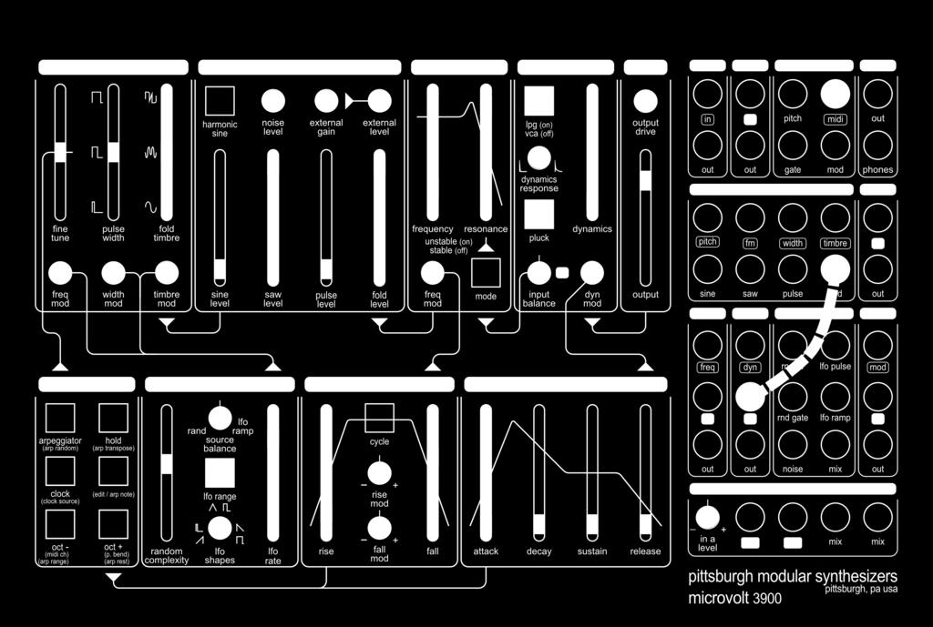
56 19. Microvolt Patch Example 2 Inverted Filter Frequency Modulation (A Deeper Look at the Inverting Mixer / Splitter / Offset Section) This patch uses the Inverting Mixer / Splitter / Offset Section to invert the output of the Function Generator before it is sent to the frequency modulation input of the binary filter. Understanding this patch will further expand the toolset available in the patch bay. The important user interface controls are highlighted in blue but all of the controls of the Microvolt 3900 can impact the sound and functionality of the patch. Once the initial patch is set up, experiment with one setting at a time to understand its effect on the signal path. The output of the function generator (134) is manually patched into mixer input a (135). The input a level attenuverter is turned full left to invert the function generator signal. The output of the mixer (137) is then patched into the frequency modulation input of the filter (120). 56
57 57
58 58
59 19. Microvolt Patch Example 3 Dynamic VCA Input Balance (Additive vs Subtractive) This simple patch example showcases the unique sounds available when additive and subtractive synthesis methods are used together. The important user interface controls are highlighted in blue but all of the controls of the Microvolt 3900 can impact the sound and functionality of the patch. Once the initial patch is set up, experiment with one setting at a time to understand its effect on the signal path. The output of the saw wave passes through the filter to create the subtractive signal path and is modified using the filter frequency slider (15) and resonance slider (16). The additive signal path is created by manually patching the output of the fold wave (117) into the input of the dynamic VCA (124) bypassing the filter and allowing the fold timbre slider (3) full control over the harmonic content of the fold wave. The input balance trimmer knob (23) controls the mix between the saw (full left) and the fold wave (full right). To maximize the organic richness of the sound, the dynamic VCA is set to LPG mode (19) with pluck enabled (22). Modulation of this patch is handled with 3 sources. The modulation sources section is set to modulate the timbre wave (6) using the triangle wave of the LFO. This creates some movement in the additive synthesis signal path. The function generator controls the modulation of the filter frequency (17) and is triggered when a midi note is received. The dynamic VCA envelope generator triggers the dynamic VCA pluck. The attack of the envelope generator needs to be set with a short attack otherwise the slope of the attack will not trigger the pluck circuit. 59
60 19. Microvolt Patch Example 4 Modulating the Binary Filter with Multiple Sources (Using the Inverting Mixer / Splitter / Offset Section) This small patch highlights an important part of the Microvolt 3900 patchbay. The Inverting Mixer / Splitter / Offset section offers several useful tools that can be utilized in almost every patch. Understanding this patch will expand the toolset available in the patch bay. The important user interface controls are highlighted in blue but all of the controls of the Microvolt 3900 can impact the sound and functionality of the patch. Once the initial patch is set up, experiment with one setting at a time to understand its effect on the signal path. In this example the ramp output of the LFO is patched into input a (135) of the mixer. This allows the level of the LFO to be adjusted using the input a atteunverter (45). The output of the function generator (134) is patched into input b (136) of the mixer and joined with the LFO signal. The output of the mixer (137) is patched into the frequency CV input of the filter (120). The amount of LFO sent to the filter cutoff in relation to the function generator output can be adjusted using the input a attenuverter. The second output of the mixer (138) is patched into the dynamics CV input of the dynamic VCA (123). This controls the output level of the dynamic VCA. The modulation mix out (131) is patched into the modulation input of the function generator. This allows for some variation in the length of the envelope based on the output of the LFO. 60
61 61
62 62
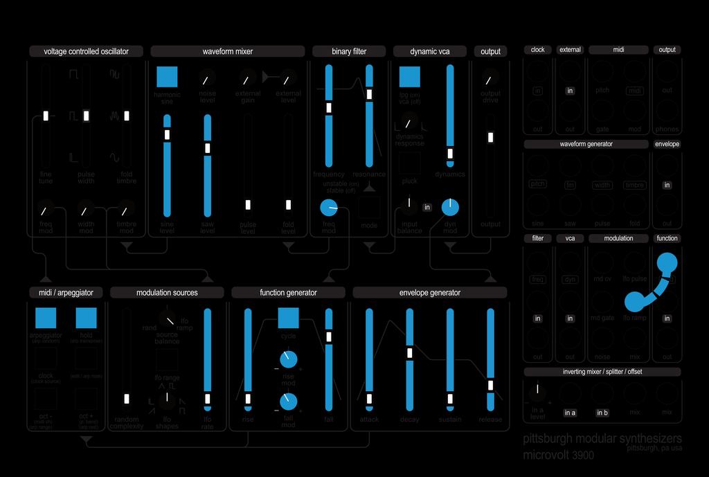
63 19. Microvolt Patch Example 5 Ratcheting Filter Frequency (Modulating a Cycling Function Generator) Another patch highlighting the function generator. This patch uses the ramp output of the LFO to modulate the rate of a cycling function generator while using the arpeggiator. Depending on how the rise and fall modulation attenuators (41 & 42) are set, the results can be similar to ratcheting or a bouncing ball type effect. Understanding this patch will further expand the functionality of the function generator as a modulation source. The important user interface controls are highlighted in blue but all of the controls of the Microvolt 3900 can impact the sound and functionality of the patch. Once the initial patch is set up, experiment with one setting at a time to understand its effect on the signal path. Patch the LFO ramp output (129) into the function generator modulation input (132). The rate of the LFO now controls the rate of the function generator which controls the frequency of the filter cutoff. This can be a nice mellow patch to tweak. Replace the LFO with the random CV output (126) and adjust the function generator rise and fall modulation attenuators (41 & 42) for more of a beat synced effect. 63
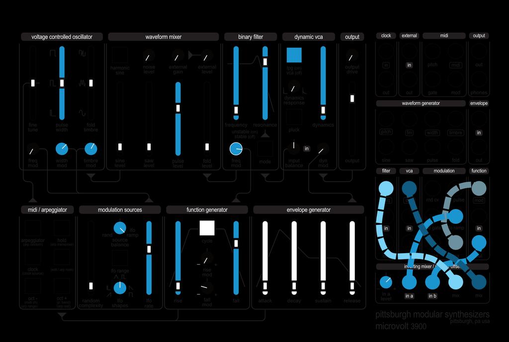
64 19. Microvolt Patch Example 6 Autonomous Control (Managing A Chaotic System) This patch explores the process of building a self-sustaining chaotic system using multiple levels of pseudorandom modulation to create a semi-autonomous synthesis creature. This is a complex patch that showcases several important concepts. Understanding this patch will help with further experimentation into the world of autonomous synthesis. The important user interface controls are highlighted in blue but all of the controls of the Microvolt 3900 can impact the sound and functionality of the patch. Once the initial patch is set up, experiment with one setting at a time to understand its effect on the signal path. The chaotic nature of this patch starts with the clock source. The function generator with cycle (39) enabled is used as the clock source for the random complexity (33). The output of the function generator (134) is manually patched into the clock input (100). (See the midi / arpeggiator section of the manual to learn how to set the clock source to external gate) In the context of a random system, the function generator makes an interesting clock source. Manually patching the output of the random CV (126) through the signal splitter (136) to (138) into the modulation input of the function generator (132) and adjusting the rise modulation (41) and fall modulation (42) creates an interesting random clock tempo. The pitch of the oscillator is randomized using the random CV (126) through the signal splitter (136) to (137) into the pitch input. The random gate output (128) is sent to the envelope generator input (118) to trigger the envelope. The output of the envelope generator (119) is patched into the frequency modulation input of the filter (120) to modulate the filter cutoff frequency. The sharp attack of the envelope also triggers the dynamic VCA pluck circuit and enables the dynamic response trimmer pot to set the duration of the sound. 64
65 65
66 20. Midi Factory Reset Performing a factory reset returns all of the stored settings to the default setting. Hold down edit first then hold down octave - and octave + for 5 seconds. The arpeggiator button, hold button, clock button, octave - button, and octave + button will blink to show the reset is complete. 66
67 67
68 21. Service and Other Information Please contact us for service or other information related to the Microvolt 3900 or any other Pittsburgh Modular product. 68
69 22. Warranty For a period of one year after the date of original purchase, the Microvolt 3900 manufactured by Pittsburgh Modular Synthesizers LLC, is warranted to function properly and be free of defects in materials and workmanship. Should a factory installed hardware fail during the warranty period, contact Pittsburgh Modular Synthesizers LLC. We will repair it (or at our option, replace it) at no charge, and pay the cost of shipping it back to you. This warranty is void if in our opinion the Microvolt 3900 has been damaged by accident, mishandled, altered, improperly serviced, or repaired by the customer where such treatment has affected its performance or reliability. This includes but is not limited to damage related to using a power adapter not supplied by Pittsburgh Modular Synthesizer LLC. In the event of such misuse/abuse by the customer, costs for repairs plus two-way shipping costs will be borne by the customer. Products found defective should be returned to the factory carefully packed, as the customer will be responsible for freight damage. Incidental or consequential damages or costs incurred as a result of product malfunction are not the responsibility of Pittsburgh Modular Synthesizers LLC. 69

70 70
pittsburgh modular synthesizers lifeforms sv-1 user manual v.1
 pittsburgh modular synthesizers lifeforms sv-1 user manual v.1 the heart and soul of modular synthesis The Pittsburgh Modular Synthesizers Lifeforms SV-1 is a complete dual oscillator synthesizer, designed
PITTSBURGH MODULAR SYSTEM 10.1 and SYNTHESIZER MANUAL AND PATCH GUIDE
 PITTSBURGH MODULAR SYSTEM 10.1 and 10.1+ SYNTHESIZER MANUAL AND PATCH GUIDE 1 Important Instructions PLEASE READ Read Instructions: Please read the System 10.1 Synthesizer manual completely before use
PITTSBURGH MODULAR FOUNDATION 3.1 and 3.1+ SYNTHESIZER MANUAL AND PATCH GUIDE
 PITTSBURGH MODULAR FOUNDATION 3.1 and 3.1+ SYNTHESIZER MANUAL AND PATCH GUIDE 1 Important Instructions PLEASE READ Read Instructions: Please read the Foundation 3.1 Synthesizer manual completely before
MMO-3 User Documentation
 MMO-3 User Documentation nozoid.com/mmo-3 1/15 MMO-3 is a digital, semi-modular, monophonic but stereo synthesizer. Built around various types of modulation synthesis, this synthesizer is mostly dedicated
Quick Start. Overview Blamsoft, Inc. All rights reserved.
 1.0.1 User Manual 2 Quick Start Viking Synth is an Audio Unit Extension Instrument that works as a plug-in inside host apps. To start using Viking Synth, open up your favorite host that supports Audio
VK-1 Viking Synthesizer
 VK-1 Viking Synthesizer 1.0.2 User Manual 2 Overview VK-1 is an emulation of a famous monophonic analog synthesizer. It has three continuously variable wave oscillators, two ladder filters with a Dual
MMO-4 User Documentation
 MMO-4 User Documentation nozoid.com This is a preliminary documentation 1/9 Feature This is the audio path wired inside the synthesizer. Modulation CV are routed to modulation fader in a digital matrix.
OCS-2 User Documentation
 OCS-2 User Documentation nozoid.com 1/17 Feature This is the audio path wired inside the synthesizer. The VCOs are oscillators that generates tune The MIX allow to combine this 2 sound sources into 1 The
Q179 Envelope++ Q179 Envelope++ Specifications. Mar 20, 2017
 Mar 20, 2017 The Q179 Envelope++ module is a full-featured voltage-controlled envelope generator with many unique features including bizarre curves, a VCA and looping. Special modes offer dual-envelopes
STO Limited Warranty Installation Overview
 v2.5 2 STO Limited Warranty ----------------------------------------------------3 Installation --------------------------------------------------4 Overview --------------------------------------------------------5
Tinysizer. Anyware Instruments Tinysizer Analog Modular System
 In the laboratory of the mad Professor Thomas Welsch (a.k.a. Tommy Analog), a baby monster was born. Don t get fooled by its size, as I mentioned: it is a monster! Has a monster sound and monstrous possibilities
semi-mod lar analog synthesizer Operation Man al
 semi-mod lar analog synthesizer Operation Man al Written and produced by Jered Flickinger Copyright 2007 Future Retro Synthesizers TABLE OF CONTENTS 1 Introduction 2. Welcome Overview Power Care Warranty
Use the patch browser to load factory patches or save or load your own custom patches.
 1.0.1 User Manual 2 Overview Movement is an eight-stage arbitrary waveform generator that can act as an envelope, LFO, or high-frequency oscillator depending on how it is configured. The interactive graphical
Q181EB Expression Block Controller
 The controller produces a voltage as you press the block, similar to the Ondes Martenot and other instruments. Perfect for controlling amplitude as you play notes on the keyboard, to control filter frequency,
Q181RC Ribbon Controller
 The Controller produces a varying voltage as you move your finger along the ribbon strip. Great for pitch bending, playing notes, controlling filter frequency, or other parameters in the synthesizer system.
VCA. Voltage Controlled Amplifier.
 VCA Voltage Controlled Amplifier www.tiptopaudio.com Tiptop Audio VCA User Manual The Tiptop Audio VCA is a single-channel variable-slope voltage-controlled amplifier in Eurorack format. It has the following
Table of Contents: Limited Warranty:
 v 1.0 2 Table of Contents: ----------------------------------------------------2 Limited Warranty: ----------------------------------------------------3 Installation: ------------------------------------------------------------4
Mixer Section. Sample & Hold (S\H) Section MIXER S\H
 Section MIXER S\H") Sample & Hold (S\H) Section Mixer Section S\H S\H IN Selects the parameter that the S&H will "sample" to input the note in the capacitor sequencer. ACCENT The S&H track can be used as an accent track.
Sample & Hold (S\H) Section Mixer Section S\H S\H IN Selects the parameter that the S&H will "sample" to input the note in the capacitor sequencer. ACCENT The S&H track can be used as an accent track.
the blooo VST Software Synthesizer Version by Björn Full Bucket Music
 the blooo VST Software Synthesizer Version 1.0 2010 by Björn Arlt @ Full Bucket Music http://www.fullbucket.de/music VST is a trademark of Steinberg Media Technologies GmbH the blooo Manual Page 2 Table
BoomTschak User s Guide
 BoomTschak User s Guide Audio Damage, Inc. 1 November 2016 The information in this document is subject to change without notice and does not represent a commitment on the part of Audio Damage, Inc. No
TURN2ON BLACKPOLE STATION POLYPHONIC SYNTHESIZER MANUAL. version device by Turn2on Software
 MANUAL version 1.2.1 device by Turn2on Software http://turn2on.ru Introduction Blackpole Station is a new software polyphonic synthesizer for Reason Propellerhead. Based on 68 waveforms in 3 oscillators
Aalto Quickstart version 1.1
 Aalto Quickstart version 1.1 Welcome to Aalto! This quickstart guide assumes that you are familiar with using softsynths in your DAW or other host program of choice. It explains how Aalto's dial objects
Helm Manual. v Developed by: Matt Tytel
 Helm Manual v0.9.0 Developed by: Matt Tytel Table of Contents General Usage... 5 Default Values... 5 Midi Learn... 5 Turn a Module On and Of... 5 Audio Modules... 6 OSCILLATORS... 7 1. Waveform selector...
// K3020 // Dual VCO. User Manual. Hardware Version E October 26, 2010 Kilpatrick Audio
 // K3020 // Dual VCO Kilpatrick Audio // K3020 // Dual VCO 2p Introduction The K3200 Dual VCO is a state-of-the-art dual analog voltage controlled oscillator that is both musically and technically superb.
SYSTEM-100 PLUG-OUT Software Synthesizer Owner s Manual
 SYSTEM-100 PLUG-OUT Software Synthesizer Owner s Manual Copyright 2015 ROLAND CORPORATION All rights reserved. No part of this publication may be reproduced in any form without the written permission of
PHENOL. Introduction. User Manual. Manual Sections. Download a PDF version of the manual here: phenol-manual.pdf
 PHENOL User Manual Download a PDF version of the manual here: phenol-manual.pdf Note that PDF manuals are automatically generated from webpages. Links and embedded media will not be accessible. For the
Q181V Whammy Bar Controller
 This document covers our Whammy Bar controllers in these configurations: Q181V1 Single-axis Whammy Bar in a single-channel Q181 panel Q181V1 Whammy Bar Q182V2 Dual-axis Whammy Bar in a dual-channel Q182
SNAKEBITE SYNTH. User Manual. Rack Extension for Propellerhead Reason. Version 1.2
 SNAKEBITE SYNTH Rack Extension for Propellerhead Reason User Manual Version 1.2 INTRODUCTION Snakebite is a hybrid digital analog synthesizer with the following features: Triple oscillator with variable
Q107/Q107A State Variable Filter
 Apr 28, 2017 The Q107 is dual-wide, full-featured State Variable filter. The Q107A is a single-wide version without the Notch output and input mixer attenuator. These two models share the same circuit
the blooo VST Software Synthesizer Version by Björn Full Bucket Music
 the blooo VST Software Synthesizer Version 1.1 2016 by Björn Arlt @ Full Bucket Music http://www.fullbucket.de/music VST is a trademark of Steinberg Media Technologies GmbH the blooo Manual Page 2 Table
Introduction. TUNE Explained:
 Introduction. The TOMS909 is a recreation of Roland's legendary TR-909 analog Tom drums sound generator for use in modular synthesizer format. The TOMS909 includes all the original controls found on the
Table of Contents: Limited Warranty:
 v 1.0 2 Table of Contents: ----------------------------------------------------2 Limited Warranty: ----------------------------------------------------3 Installation: -------------------------------------------------------------4
Limited WARRANTY: Make Noise implies and accepts no responsibility for harm to person or apparatus caused through operation of this product.
 v 1.0 Limited WARRANTY: Make Noise warrants this product to be free of defects in materials or construction for a period of one year from the date of purchase (proof of purchase/invoice required). Malfunction
Glossary DAW Patch Preset Voice
 OPERATOR'S MANUAL 1 Table of contents Glossary... 3 System requirements... 4 Overview... 5 Operating the controls... 5 Working with patches... 6 VST version... 6 Audio Unit version... 6 Building your sound...
AtomoSynth MochikaX2 v1.0
 AtomoSynth MochikaX2 v1.0 Thank you for purchasing the AtomoSynth, Mochika X2 version 1.0. Analog synthesizer sequencer. In order to enjoy long and trouble free use, please read this manual carefully and
I personally hope you enjoy this release and find it to be an inspirational addition to your musical toolkit.
 1 CONTENTS 2 Welcome to COIL...2 2.1 System Requirements...2 3 About COIL...3 3.1 Key Features...3 4 Getting Started...4 4.1 Using Reaktor...4 4.2 Included Files...4 4.3 Opening COIL...4 4.4 Control Help...4
REV 7. v.1.16
 5.19.16 REV 7 v.1.16 1 FCC: ----------------------------------------------------------------------2 Limited Warranty: ----------------------------------------------------3 Overview:------------------------------------------------------------4
JUNO-106. PLUG-OUT Software Synthesizer Owner s Manual 01A. Copyright 2017 ROLAND CORPORATION
 JUNO-106 PLUG-OUT Software Synthesizer Owner s Manual Copyright 2017 ROLAND CORPORATION 01A Introduction When using the JUNO-106 for the first time, you must specify the MIDI Input/Output setting in the
User Guide V
 XV User Guide V1.10 25-02-2017 Diode Ladder Wave Filter Thank you for purchasing the AJH Synth Sonic XV Eurorack synthesiser module, which like all AJH Synth products, has been designed and handbuilt in
Limited WARRANTY: Make Noise implies and accepts no responsibility for harm to person or apparatus caused through operation of this product.
 v2.6 2 DPO Limited Warranty ----------------------------------------------------3 Installation --------------------------------------------------4 Overview ----------------------------------------------------------5
Mono/Fury. VST Software Synthesizer. Version by Björn Full Bucket Music
 Mono/Fury VST Software Synthesizer Version 1.0 2010-2012 by Björn Arlt @ Full Bucket Music http://www.fullbucket.de/music VST is a trademark of Steinberg Media Technologies GmbH Mono/Poly is a registered
PULSAR DUAL LFO OPERATION MANUAL
 PULSAR DUAL LFO OPERATION MANUAL The information in this document is subject to change without notice and does not represent a commitment on the part of Propellerhead Software AB. The software described
P9700S Overview. In a P9700S, the 9700K MIDI2CV8 is the power source for the other modules in the kit. A separate power supply is not needed.
 P9700S Overview In a P9700S, the 9700K MIDI2CV8 is the power source for the other modules in the kit. A separate power supply is not needed. The wall-mount transformer for the 9700K is an ac power source
Please contact with any questions, needs & comments... otherwise go MAKE NOISE.
 DPO Limited WARRANTY: Make Noise warrants this product to be free of defects in materials or construction for a period of one year from the date of manufacture. Malfunction resulting from wrong power supply
MKII. Tipt p + + Z3000. FREQUENCY Smart VC-Oscillator PULSE WIDTH PWM PWM FM 1. Linear FM FM 2 FREQUENCY/NOTE/OCTAVE WAVE SHAPER INPUT.
 MKII 1V/ EXT-IN 1 Linear 2 Smart VCOmkII Design - Gur Milstein Special Thanks Matthew Davidson Shawn Cleary Richard Devine Bobby Voso Rene Schmitz Mark Pulver Gene Zumchack Surachai Andreas Schneider MADE
Analog Synthesizer: Functional Description
 Analog Synthesizer: Functional Description Documentation and Technical Information Nolan Lem (2013) Abstract This analog audio synthesizer consists of a keyboard controller paired with several modules
Atlantis Manual. Atlantis. Dual Oscillator Subtractive Synth Voice. Manual Revision:
 Atlantis Dual Oscillator Subtractive Synth Voice Manual Revision: 2017.09.25 Table of Contents Table of Contents Overview Basic Features Sound Generators Filter Modulators Mixing and Output Installation
FXDf Limited Warranty: Installation: Expansion:
 v2.3 1 FXDf Limited Warranty:----------------------------------------2 Installation: --------------------------------------------------3 Expansion: ------------------------------------------------------4
D O C U M E N T A T I O N
 DOCUMENTATION Introduction This is the user manual for Enkl - Monophonic Synthesizer, developed by Klevgränd produktion. The synthesizer comes in two versions an ipad app and a Desktop plugin (AU & VST).
Plaits. Macro-oscillator
 Plaits Macro-oscillator A B C D E F About Plaits Plaits is a digital voltage-controlled sound source capable of sixteen different synthesis techniques. Plaits reclaims the land between all the fragmented
the blooo Software Synthesizer Version by Björn Full Bucket Music
 the blooo Software Synthesizer Version 2.1 2010 2017 by Björn Arlt @ Full Bucket Music http://www.fullbucket.de/music VST is a trademark of Steinberg Media Technologies GmbH Windows is a registered trademark
HexVCA Manual v1.0. Front Panel. 1 - VCA Offset CV offset, also referred to as bias knob. CV indicator LED. 2 - IN 1-6 The signal input of the VCAs.
 HexVCA Manual v1.0 The HexVCA contains six separate DC coupled logarithmic VCAs that have their outputs normalled to two outputs. The front panel outputs of each VCA is a switching jack which breaks the
GEN/MDM INTERFACE USER GUIDE 1.00
 GEN/MDM INTERFACE USER GUIDE 1.00 Page 1 of 22 Contents Overview...3 Setup...3 Gen/MDM MIDI Quick Reference...4 YM2612 FM...4 SN76489 PSG...6 MIDI Mapping YM2612...8 YM2612: Global Parameters...8 YM2612:
MMG: Limited Warranty: Installation:
 v2.4 2 MMG: Limited Warranty: ----------------------------------------------------3 Installation: ----------------------------------------------------4 Overview:---------------------------------------------------------------5
INSANITY SAMPLES. Presents
 INSANITY SAMPLES Presents A 3 oscillator super synth modelled on a mixture of analogue beasts. Designed to tap into both the classic analogue sound, whilst stepping out into the modern age with a multitude
Manual. Powered by RPCX
 Powered by RPCX Manual WELCOME In the Rob Papen world of synthesis there was one type of synthesizer missing A synthesizer that presents all its controls and features in a single window. The current Rob
Get t ing Started. Adaptive latency compensation: Audio Interface:
 Get t ing Started. Getting started with Trueno is as simple as running the installer and opening the plugin from your favourite host. As Trueno is a hybrid hardware/software product, it works differently
Music Easel Aux Card User s Guide v1.0 by Joel Davel 1/15/2017
 Music Easel Aux Card User s Guide v1.0 by Joel Davel 1/15/2017 Congratulations!!!! The Aux Card is a natural complement to the Easel and way to expand your palette. Introducing the Music Easel Auxilary
HERTZ DONUT MARK III OPERATIONS MANUAL FIRMWARE V1.0
 HERTZ DONUT MARK III OPERATIONS MANUAL FIRMWARE V1.0 FUNDAMENTALS The Hertz Donut Mark III is a complex oscillator utilizing the finest digital sound synthesis techniques from the mid-1980s. It uses a
Q106 Oscillator. Controls and Connectors. Jun 2014
 The Q106 Oscillator is the foundation of any synthesizer providing the basic waveforms used to construct sounds. With a total range of.05hz to 20kHz+, the Q106 operates as a powerful audio oscillator and
Galilean Moons. dual amplitude transmutator. USER MANUAL v1.02
 Galilean Moons dual amplitude transmutator USER MANUAL v1.02 Contents Contents... 2 Introduction... 3 Module Features and Specifications... 4 Module Description... 4 Features List... 4 Technical Details...
COS. user manual. Advanced subtractive synthesizer with Morph function. 1 AD Modulation Envelope with 9 destinations
 COS Advanced subtractive synthesizer with Morph function user manual 2 multi-wave oscillators with sync, FM 1 AD Modulation Envelope with 9 destinations LCD panel for instant observation of the changed
Contents. 1. Introduction Bank M Program Structure Parameters
 E 1 Contents Contents 1. Introduction --------------------- 1 Features of MOSS-TRI ----------------- 1 2. Bank M Program Structure -- 2 Program structure------------------------ 2 Editing --------------------------------------
Tubbutec Modypoly / Modysix
 Tubbutec Modypoly / Modysix Midi retrofit and feature extension for Polysix and Poly-6 User Manual for firmware version v.4 http://tubbutec.de Contents Modysix 3 2 Play Modes 3 2. Play Modes Overview......................
Semi-modular audio controlled analog synthesizer
 Semi-modular audio controlled analog synthesizer Owner s manual 21.7.2017 - Sonicsmith Hello and thank you for purchasing a Squaver P1 synthesizer! The Squaver P1 is a semi-modular, audio controlled, analog
A-110 VCO. 1. Introduction. doepfer System A VCO A-110. Module A-110 (VCO) is a voltage-controlled oscillator.
 is a voltage-controlled oscillator.") doepfer System A - 100 A-110 1. Introduction SYNC A-110 Module A-110 () is a voltage-controlled oscillator. This s frequency range is about ten octaves. It can produce four waveforms simultaneously: square,
doepfer System A - 100 A-110 1. Introduction SYNC A-110 Module A-110 () is a voltage-controlled oscillator. This s frequency range is about ten octaves. It can produce four waveforms simultaneously: square,
ENSEMBLE String Synthesizer
 ENSEMBLE String Synthesizer by Max for Cats (+ Chorus Ensemble & Ensemble Phaser) Thank you for purchasing the Ensemble Max for Live String Synthesizer. Ensemble was inspired by the string machines from
Make Noise Maths V2 Illustrated supplement. by Demonam
 Make Noise Maths V2 Illustrated supplement by Demonam Index 01... Typical Voltage Controlled Triangle Function (Triangle LFO) 02... Typical Voltage Controlled Ramp Function (Saw/ Ramp LFO) 03... Arcade
SZCZ s AUDIO ADVENTURES.
 SZCZ s AUDIO ADVENTURES user s guide www.fairlyconfusing.net Licence and technical information Sawmill is a virtual instrument for Native Instruments Kontakt sampler, you need full version of Kontakt 5.8.1
Written by Jered Flickinger Copyright 2017 Future Retro
 Written by Jered Flickinger Copyright 2017 Future Retro www.future-retro.com TABLE OF CONTENTS Page 1 - Overview Page 2 Inputs and Outputs Page 3 Controls Page 4 Modulation Sources Page 5 Parameters Instrument
Grendel Drone Commander CLASSIC PEDAL Analog Music Synthesizer. Rare Waves LLC USA rarewaves.net
 CLASSIC PEDAL Analog Music Synthesizer Rare Waves LLC USA rarewaves.net What is it? is a unique synthesizer that delivers thick drone tones with the convenience of an FX pedal stompbox. brings back the
DOEPFER System A-100 Synthesizer Voice A Introduction. Fig. 1: A sketch
 DOEPFER System A-100 Synthesizer Voice A-111-5 1. Introduction Fig. 1: A-111-5 sketch 1 Synthesizer Voice A-111-5 System A-100 DOEPFER Module A-111-5 is a complete monophonic synthesizer module that includes
P. Moog Synthesizer I
 P. Moog Synthesizer I The music synthesizer was invented in the early 1960s by Robert Moog. Moog came to live in Leicester, near Asheville, in 1978 (the same year the author started teaching at UNCA).
Atlantis Manual. Atlantis. Dual Oscillator Subtractive Synth Voice. Manual Revision:
 Atlantis Dual Oscillator Subtractive Synth Voice Manual Revision: 2018.09.13 Table of Contents Table of Contents Compliance Installation Installing Your Module Overview Basic Features Sound Generators
TiaR c-x-f synth rev 09. complex X filter synthesizer. A brief user guide
 1 Introduction TiaR c-x-f synth rev 09 complex X filter synthesizer A brief user guide by Thierry Rochebois The cxf synthesizer is a jsfx software synthesizer designed for Reaper. It can be downloaded
Square I User Manual
 Square I User Manual Copyright 2001 rgcaudio Software. All rights reserved. VST is a trademark of Steinberg Soft- und Hardware GmbH Manual original location: http://web.archive.org/web/20050210093127/www.rgcaudio.com/manuals/s1/
TABLE OF CONTENTS 1. MAIN PAGE 2. EDIT PAGE 3. LOOP EDIT ADVANCED PAGE 4. FX PAGE - LAYER FX 5. FX PAGE - GLOBAL FX 6. RHYTHM PAGE 7.
 Owner s Manual OWNER S MANUAL 2 TABLE OF CONTENTS 1. MAIN PAGE 2. EDIT PAGE 3. LOOP EDIT ADVANCED PAGE 4. FX PAGE - LAYER FX 5. FX PAGE - GLOBAL FX 6. RHYTHM PAGE 7. ARPEGGIATOR 8. MACROS 9. PRESETS 10.
ZEEON synth User guide
 ZEEON synth User guide version 1.0 BeepStreet 2017 Introduction 2 Application 2 Audio unit 3 Control panel 3 Presets 4 Voice signal flow 4 Oscillators 5 Mixer 5 Filter 6 Envelope generators 6 Low frequency
Station X/Y. User Manual. Analogue solutions 2010
 Station X/Y User Manual Analogue solutions 2010 Station X/Y Minimodular Synthesisers Introduction We originally introduced a minimodular system of this size back in 2001. It ran for a few years. Now in
Rainbow is copyright (c) 2000 Big Tick VST Plugin-In Technology by Steinberg. VST is a trademark of Steinberg Soft- und Hardware GmbH
 2000 Big Tick VST Plugin-In Technology by Steinberg. VST is a trademark of Steinberg Soft- und Hardware GmbH") Introduction Rainbow is Big Tick's software synthesizer for Microsoft Windows. It can be used either as a standalone synth, or as a plugin, based on VST 2.0 specifications. It can be downloaded at http://www.bigtickaudio.com
Introduction Rainbow is Big Tick's software synthesizer for Microsoft Windows. It can be used either as a standalone synth, or as a plugin, based on VST 2.0 specifications. It can be downloaded at http://www.bigtickaudio.com
MODEL 9791 HERTZ DONUT OPERATOR S MANUAL. Dual DIgital Oscillator with Internal Modulation Bus
 MODEL 9791 HERTZ DONUT OPERATOR S MANUAL Dual DIgital Oscillator with Internal Modulation Bus THE HARVESTMAN-9791 HERTZ DONUT USER S MANUAL Front Panel Key Introduction Table of Contents Configuration
MANUAL v.1c CONTACT MORE THAN LOGIC. UNITING ART + ENGINEERING.
 MANUAL v.1c MORE THAN LOGIC. UNITING ART + ENGINEERING. CONTACT email: info@meris.us phone: 747.233.1440 website: www.meris.us TABLE OF CONTENTS SECTION 1 PG. 1 FRONT PANEL CONTROLS SECTION 2 PG. 2-4 GLOBAL
FILTER 8 MULTIMODE FILTER/8-PHASE OSCILLATOR CONTENTS INTRODUCTION
 INTRODUCTION Representing the cutting edge in modular analogue voltage controlled filter (VCF) design, Filter 8 offers more possibilities and higher fidelity in 12 HP than ever before. Starting from the
Welcome to Bengal The semi-modular FM Synthesizer System
 OPERATION MANUAL v.1.0 Welcome to Bengal The semi-modular FM Synthesizer System Thank you for choosing Max for Cats - the new sound is yours! We hope you enjoy using Bengal in your music as much as we
PRELIMINARY USER S MANUAL OCTOBER 2012
 PRELIMINARY USER S MANUAL OCTOBER 2012 The MAGMA will make you go back into the 80's sounds with sonorities. The sound engine is inspired from the SH series by Roland, which had a waveform mix and a sequencer.
NOZORI 84 modules documentation
 NOZORI 84 modules documentation A single piece of paper can be folded into innumerable shapes. In the same way, a single Nozori hardware can morph into multiple modules. Changing functionality is as simple
Q106A Oscillator. Aug The Q106A Oscillator module is a combination of the Q106 Oscillator and the Q141 Aid module, all on a single panel.
 Aug 2017 The Q106A Oscillator module is a combination of the Q106 Oscillator and the Q141 Aid module, all on a single panel. The Q106A Oscillator is the foundation of any synthesizer providing the basic
User Guide. Ring Modulator - Dual Sub Bass - Mixer
 sm User Guide Ring Modulator - Dual Sub Bass - Mixer Thank you for purchasing the AJH Synth Ring SM module, which like all AJH Synth Modules, has been designed and handbuilt in the UK from the very highest
Bastl Instruments x Casper Electronics
 SoftPop SoftPop SoftP Bastl Instruments x Casper Electronics INTRO SoftPop INTRO S INTRO Thanks to the Bastl community for the endless support and constant inspiration through our shared love of synths
Anyware Instruments MOODULATOR. User s Manual
 Anyware Instruments MOODULATOR User s Manual Version 1.0, September 2015 1 Introduction Congratulations and thank you for purchasing the MOODULATOR compact classic synthesizer! The concept behind this
Owner s Manual. Page 1 of 23
 Page 1 of 23 Installation Instructions Table of Contents 1. Getting Started! Installation via Connect! Activation with Native Instruments Service Center 2. Pulse Engines Page! Pulse Engine Layers! Pulse
This is the manual for
 This is the manual for by copysomething stuff 2012 document version 1.0 last edited 2013-07-30 1 Table of Contents 1. Intro...3 1.1 Basic description...3 1.2 General design and usage philosophy...4 2 In
Shifting Inverting Signal Mingler (SISM) from 4ms Company Eurorack Module User Manual
 from 4ms Company Eurorack Module User Manual") Shifting Inverting Signal Mingler (SISM) from 4ms Company Eurorack Module User Manual The Shifting Inverting Signal Mingler (SISM) is a 4-channel voltage manipulator that can scale, invert, attenuate,
Shifting Inverting Signal Mingler (SISM) from 4ms Company Eurorack Module User Manual The Shifting Inverting Signal Mingler (SISM) is a 4-channel voltage manipulator that can scale, invert, attenuate,
EXCLUSIVELY ANALOGUE THE ANALOGUE SYNTHESIZER SPECIALISTS (UNIT 1) 18 THE MEADOWS, CHESTERFIELD, DERBYSHIRE, S42 7JY, ENGLAND
 18 THE MEADOWS, CHESTERFIELD, DERBYSHIRE, S42 7JY, ENGLAND") 1 EXCLUSIVELY ANALOGUE THE ANALOGUE SYNTHESIZER SPECIALISTS (UNIT 1) 18 THE MEADOWS, CHESTERFIELD, DERBYSHIRE, S42 7JY, ENGLAND 01246 272150 INTRODUCTION THE AVIATOR OWNERS MANUAL Welcome to the "AVIATOR"
1 EXCLUSIVELY ANALOGUE THE ANALOGUE SYNTHESIZER SPECIALISTS (UNIT 1) 18 THE MEADOWS, CHESTERFIELD, DERBYSHIRE, S42 7JY, ENGLAND 01246 272150 INTRODUCTION THE AVIATOR OWNERS MANUAL Welcome to the "AVIATOR"
PowerCore 01 Manual. Manual for PowerCore 01
 PowerCore 01 Manual English Manual for PowerCore 01 SUPPORT AND CONTACT DETAILS TABLE OF CONTENTS TC SUPPORT INTERACTIVE The TC Support Interactive website www.tcsupport.tc is designed as an online support
Free SE-1X Manual Version 0.1 (Covers OS Version 0.75)
") Free SE-1X Manual Version 0.1 (Covers OS Version 0.75) Copyright c 2005, by Nectarine City, LLC. See the LICENSE section of this document for the details of your rights regarding this document. January
Free SE-1X Manual Version 0.1 (Covers OS Version 0.75) Copyright c 2005, by Nectarine City, LLC. See the LICENSE section of this document for the details of your rights regarding this document. January
ALM-011. Akemie s Castle. - Operation Manual -
 ALM-011 Akemie s Castle - Operation Manual - (V0.2) Introduction... 3 Technical Specifications 3 Background & Caveats... 4 Core Operation... 5 Panel Layout 5 General Usage 7 Patch Ideas... 13 Tuning Calibration...
What you get. Thank you for ordering Erica Synths Acidbox lll! FEATURES SPECS
 Thank you for ordering Erica Synths Acidbox lll! Erica Synths AcidboxIII brings you the core of the famous Polivoks VCF in stereo version with unique audio signal overdrive circuit, built in LFO and envelope
Mixwitch Mixer & Switcher
 Mixwitch Mixer & Switcher Voltage & clock-controlled analog switch with mixer Introduction Focused versatility seems an oxymoron when describing the features that led us to design the Mixwitch. With only
LFO RATE VCO LFO AMT VCF LFO AMT ATTACK DECAY/ RELEASE SUSTAIN
 MIDI FINE TUNE MIX MOD FREQ 320Hz 80Hz 20Hz 5KHz 20KHZ VCO 2 FILTER VCA CUTOFF ENVELOPE VCO 1 LVL VCO 2 LVL RES EG AMOUNT RELEASE LFO RATE VCO LFO AMT VCF LFO AMT ATTACK DECAY/ RELEASE SUSTAIN FILTER AMPLIFIER