Unlicensed Wireless Multipoint System in Sacramento Metro. Motorola Canopy
|
|
|
- Alan Miller
- 5 years ago
- Views:
Transcription

1 Unlicensed Wireless Multipoint System in Sacramento Metro Motorola Canopy
2 The Problem No broadband communication available to four cameras in the Sacramento Metro Area. Date Line June 2004
3 The Options POTS line Microwave Wireless link GPRS Wireless link
4 Feasibility Requirements Permission to mount radios on DGS Tower Permission to mount radios on TMC Tower Time time to receive tower permissions Line of Sight RF Environment analysis Costs
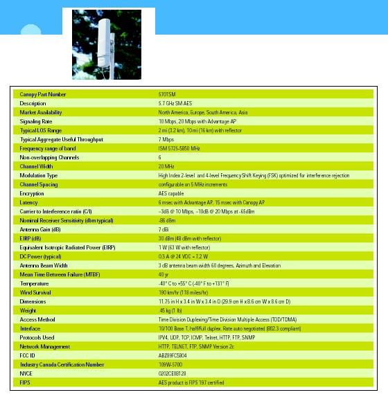
5 The Choice Multi-Point Microwave link to central communication tower and a separate backhaul link to D3 RTMC Motorola Canopy 5.7 GHz U-NII Band, 6 channels at 20MHz Deployed World Wide Proven reliability with ISP and Carriers
6

7 HD23444 Stinger Passive Gain Antenna for 5.7 GHz SMs Slip on an extra GHz. Extend your range to 5 miles without using a large reflector. Boost signal levels for marginal customers. Speed up your installs Narrows the pattern to 12 degrees Lowers Jitter Typical gain increase from 12 to 14 db.
8 Controlling Interference: The Canopy Approach Interference in a PMP BWA network,either self-induced or external, is generally an issue more for the Access Point (AP) than for Subscriber Modules (SM). At the AP, typically antennas with much wider angles are used so that they may communicate with many SMs spread over a given geography.. Beam widths for these devices can range from 45 to 360 degrees. The wider the angle, the more potential there exists for either selfinterference or external interference. Because a single AP supports dozens, if not hundreds, of end users or customers, interference at this stage in the network deployment can have a large impact.
9 Controlling Interference Continued The issue in BWA networks designed to support data or IPbased traffic can be even more insidious. In this instance, a very small amount of RF interference can have a huge performance impact on the network throughput: in some instances three to four percent RF interference can result in a 40 percent reduction actual end-to-end data rates. The problem of interference in PTP networks operating in the license exempt bands, while not as severe as that encountered in PMP networks(due to the use of highly directional antennas at both ends),must still be addressed.
10 Modulation and the C/I ratio At the most fundamental level, an interfering RF source disrupts the digital transmission by making it too difficult for the receiving station to "decode" the signal. How much noise or interference a digital RF transmission can tolerate depends on the modulation used. Fundamentally, modulation is the method whereby zeros and ones are communicated by varying one of three aspects of a radio signal. The three portions of an RF signal that can be changed or modulated are phase, frequency, and amplitude. Shifting the properties of any of these parameters can be used to communicate different "states." These states, in turn, are translated to zeros and ones for binary communications.
11 Binary Frequency Shift Keying BFSK For example, with frequency modulation, if the sine wave is at frequency one, it is decoded as a zero. If the sine wave is shifted slightly to frequency two, this is decoded as a one. This type of modulation is referred to as Binary FSK (BFSK), or Frequency Shift Keying. In this example, a system must only be able to tell the difference between one of two states or phases. More complex modulations, such as 16QAM (quadrature amplitude modulation), attempt to differentiate among 16 different possible states of an incoming signal.
12 Advantage of BFSK The ability of a receiving station to decode an incoming signal at the most basic physical layer is dependent on a factor called the "carrier to interference ratio," or C/I. This fancy-sounding term means exactly what it says: how strong the desired signal (the carrier) is relative to the unwanted signals (the interference). C/I ratios are based primarily on the modulation used, with more complex modulations requiring higher C/I numbers than more robust modulations, such as BFSK.
13 More BFSK The Canopy product employs BFSK for modulation. With this modulation the C/I ratio necessary to operate properly with an error rate of 1x 10-4 bits per second is only 3dB; i.e. the wanted signal need be only 3dB higher in power than the unwanted interferers. A system operating with 16 QAM at these levels would require a C/I ratio ofroughly 12 to 14dB. Putting this into perspective, with every 3dB of additional signal strength, the power of a signal is doubled.
14 Still More BFSK This means that the Canopy system, with its C/I ratio of 3dB, can tolerate an interfering signal that is many times more powerful than a 16QAM system and still operate at the specified error rate. Canopy system employing BFSK modulation will tolerate substantially higher levels of interference before the communication stream becomes impacted. All other PHY layer techniques are designed to improve this most fundamental measurement of network robustness and operational effectiveness by sustaining the necessary C/I level.
15 Antenna Front-To-Back Ratio The front-to-back ratio of an AP antenna indicates how much of an incoming signal will be absorbed coming into the front of the antenna as compared to how much of a signal arriving at the back of the antenna is absorbed. When deploying networks in a cellular topology, the performance of the antenna in rejecting unwanted signals from behind is an important feature. The Canopy system, with its integrated antennas at the AP, has a front-to-back ratio of 20dB. Coupled with the excellent C/I ratio, this means a Canopy AP receiving a signal at threshold (the weakest signal it can still detect) can be hit with an interfering signal from behind, either internal or external, on the order of -60dBm and still support connections at an acceptable error rate.
16 Time Division Duplexing Synchronization BWA networks that use Time Division Duplexing for separating upstream and downstream communications are ideally suited for asymmetric traffic, such as data. The ability to adjust the amount of bandwidth dedicated for upstream and downstream communications without changing hardware is a powerful feature. TDD systems operate by transmitting downstream (from the AP to the SM) for a period of time -- 1ms for example. Following a short guard time, the SMs then transmit on the same frequency in the upstream.
17 TDD Continued For a cell site with more than one radio operating in TDD mode, it is important that all the sectors of the cell transmit and receive at precisely the same time. Otherwise, if sector 1 is transmitting when sector 2 is receiving, sector 2's incoming transmission can be interfered with even if they are on different frequency channels because the sector 1 signal is so close it is strong enough to "flood" or overwhelm the electronics in sector 2.
18 More TDD When deploying a TDD system in a cellular topology, it is desirable to be able to use the same frequency in each cell site even though those cell sites are possibly several miles away. This means sector 1 from AP A may interfere with sector 1 of AP B. To avoid this inter-cellular synchronization is required, making sure that all the sectors in all the cell sites are properly timed and synchronized in terms of downstream and upstream communications. With the Canopy system, designed for large scale, dense network deployments, TDD synchronization is a critical requirement. This has been solved with the use of a GPS signal. These precise satellite signals are used for timing and, ultimately, transmit/receive synchronization, thus tying all sectors in a Canopy network to the same "clock."
19 Dealing W/Interference- The MAC Layer MAC - Medium Access Control MAC Layer- That layer of a distributed communication system concerned with the control access to a medium that is shared between two or more entities The original data, an IP packet datagram, for example, is segmented into packets that fit into a radio data packet (RDP). Despite all the best deployment design and use of the extremely robust Canopy system, there will be instances where interference will overcome these measures and corrupt a MAC frame or a portion of a MAC frame. When this happens, the corrupted data must be sent again. If the MAC frame is designed for large RDPs on the order of several hundred bytes, the entire slot must be re-transmitted even if only a small amount of this packet is damaged
20 The MAC Layer Continued The impact on network throughput as a result can be large, with a few bytes in error causing hundreds of bytes to be re-sent. Canopy solves this problem by using RDPs sized at 64 bytes. With this smaller RDP size, the re-transmission can be contained to only those bytes that were damaged, thus avoiding the re-send of large chunks of valid data. The 64-byte slot could have been made even smaller, but as RDP size decreases, the slot header which is fixed becomes a more significant portion of the packet data, hence increasing the MAC layer overhead. In addition the 64-byte slot is ideally sized for handling the TCP acknowledgements sent for most IP packets.
21 The Problem With TCP TCP/IP networks were designed to operate in the wired world where interference was assumed to be negligible. The protocol design calls for a positive acknowledgement sent from the receiving station to the sending station for every IP packet sent out. If the sending station does not receive the TCP ACK in a certain amount of time, it is assumed that the cause was congestion of the network - not an error resulting from transmission impediments. When encountering congestion, TCP responds by dramatically slowing down the transmission and then increasing transmission speed slowly.
22 Automatic Retransmission Request The Canopy system solves the problem with a feature called Automatic Retransmission request or ARQ. ARQ actually inspects the RDPs that come into the receiving SM and looks for errors. If an error is detected, the SM (or AP) will send a request to the sending entity to re-send the RDP. All of this is accomplished two layers below TCP in the protocol stack. The net effect is that as far as TCP is concerned, it never receives a packet of data with an error as a result of the wireless portion of the network. This prevents TCP from invoking the slow start algorithm, keeping the end-to-end data rates at the peak or just slightly below peak operational rates.
23 IEEE Transmit Contention The IEEE standard operates in what is referred to as a distributed control manner. This means that each SM has the ability to send a packet at its own discretion. Typically in this scenario the SM will "listen," and if it does not hear any transmissions, it will assume the channel is clear and send its data. The problem arises if the sending SM cannot hear other SMs. In this instance, two or more SMs may send a packet at the same time, corrupting both and causing a retransmission. Interference is also a culprit in blocking SMs from hearing each other with the same effect
24 Centralized Transmission Control Canopy solves this contention problem by implementing a demand contention access scheme where the AP controls all transmissions in the sector, both upstream and downstream. An SM will only send its data when allowed. If an SM's request to send data is interfered with, it will wait and try again, but at no point will it ever transmit into the uplink data channel until it is permitted by the AP.
25 Expectations To stream video at a bandwidth of 150K bps. High Reliability %?
26 Reliability The simplest definition of reliability is quality over time. Since time is involved in reliability, it is often measured by a rate. Just as quality is usually measured in terms of rejects (or un-quality), reliability is measured in terms of failures (or un-reliability). (from NASA website) Reliability is a network s ability to perform a designated set of functions under certain conditions at specified operational times. Availability is a network s ability to perform its functions at any given instant under certain conditions. Average availability is a function of how often something fails and how long it takes to recover from failure.
27 Preliminary Planning The next step should be to decide on the degree of reliability or availability which the system is required to yield. Most non-technical people posed with such a question would probably respond with answers like: "The best possible, " "It must always be available when needed," or possibly "Communications are vital to be my business and no service interruptions can be tolerated." Unfortunately, these answers are of little value or help to the microwave system designer who requires a specific numeric value upon which to base the design. The appropriate selection of this value is of paramount importance, since it will affect many subsequent design decisions and the over-all cost of the system.
28 RF Design Criteria Operating frequency band Maximum path length The need for diversity Equipment failure protection Antenna size Transmitter output power Equipment selection The required traffic capacity The length of the path Frequency congestion in the area Weather conditions
29 Reliability Table Reliability % Outage time % Outage time per year hours hours hours hours hours hours minutes minutes minutes seconds
30 Reliability Continued The reliability Table shows the relationship between reliability and outage time, but it is almost impossible to predict the duration and frequency of each individual outage, which will contribute to this total value. Further, the outage time will be composed of two different reliability figures. Equipment malfunctions can be expected to be relatively rare, particularly if standby assemblies are furnished, but may be of long duration. If the microwave station is remotely located, it may take an hour or more to dispatch a technician and remedy the fault. Service interruptions due to propagation conditions will be more frequent but of short duration typically a few seconds. The permissible outage time will affect such factors as:
31 Reliability Calculations (Norwood) Unreliability= Outage Probability = Undp = a b f D 10 F 10 a = Terrain Factor = 1 (for average terrain, with some roughness) b = Climate Factor = 0.25 (for nomal interior temperate or northern areas) f = frequency in GHz D = Path length in miles F = Fade Margin in db Undp Norwood = = The percent reliability is computed from the outage probability = % R = 100 ( 1 Undp) % R = 100 ( ) = % Outage = Year = min
32 Reciprocity In Antenna Design One important point to note here is that the antenna gain is reciprocal, i.e., the antenna gain can be added to the wireless device at either end to increase the overall link budget. For example, a wireless system with a 10 dbi antenna on the transmitter and a 2 dbi antenna on the receiver will have the same range as a system with a 4 dbi antenna the transmitter and an 8 dbi antenna on the receiver, everything else being equal. Therefore, adding a high gain antenna allows a device not only to transmit signals farther, but also to receive weaker signals.
33 Calculating Rx Signal Level
34 Signal Level Calculations Link Budget =TXpwr +TXgain + Rxgain + Rxgain - (-Rxsensitivity) - FM = 23dBm + 7dBi + 10dBi(stinger) + 7dBi - (-86dB) -3dB= 130dB Rx Bryte Bend = 23dBm + 7dBi dBi(stinger) - 119dB(2.4miles) + 7dBi - 0 = -72dB Rx Northgate = 23dBm + 7dBi dBi(stinger) - 122dB(2.4miles) + 7dBi - 0 = -75dB Rx Norwood = 23dBm + 7dBi dBi(stinger) - 126dB(2.4miles) + 7dBi - 0 = -79dB Rx Raley = 23dBm + 7dBi dBi(stinger) - 126dB(2.4miles) + 7dBi - 0 = -79dB

35 Fade Margin Calculations Typically, broadband wireless systems recommend a fade margin of 10dB. The Canopy system is unique in being more tolerant of lower fade margin that other systems, and can operate reliably with a 3dB fade margin. FM Bryte Bend = -72dB - (-86dB) = 14dB FM Northgate = -75dB - (-86dB) = 11dB FM Norwood = -79dB - (-86dB) = 7dB FM Norwood = -79dB - (-86dB) = 7dB
36 Norwood Fresnel Zone Calculation F1 = The first Fresnel zone radius in feet D = the total path length in miles d1 = the distance from one end-point to the point being considered in miles d2 = D - d1 in miles f = Frequency in GHz F 1 = 72 ( d1 d 2) f D ( 0.3mi 5.1mi) F1 = 72 = GHz 5.4mi ft
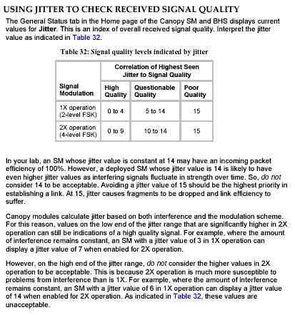
37 Jitter
38 Assumptions Bercut tower radio mounting height 220ft Spectral Density Line of Sight was good enough
39
40 Motorola s Analysis Bob Simmons (Senior Account Manager) wrote the following: The two Access Points (AP) located at the Bercut site will facilitate the connections to all four of the camera sites, with on one AP providing connections for the Northgate, Norwood, and Raley sites (as these sites appear to be within a 60 degree sector), and the other AP facilitating the connection to the Bryte Bend Bridge. The Cluster Management Module (CMM) will provide the clocking for all the radios in this application. I have also included 2 Ethernet surge suppressors at each remote location with the assumption that there will be a high level of radio activity in the area. If you feel that there is a minimal amount of RF interference at these locations, you may choose to install a single surge suppression unit at the bottom of the Ethernet cable run on the tower.
41 Motorola Caveats With regards to the path analysis: I wanted to mention that the path analysis information noted does not make allowances for any man-made or vegetative obstacles which may be in the transmission path. I also want to note that as the antenna heights at each of the remote camera sites are relatively low, any man-made or vegetative obstacles which may be in close proximity to the remote camera sites may cause the link to be unreliable. Please be advised that the Canopy units require a line of sight transmission path (which includes a minimum requirement for an 80% Fresnel Zone clearance for the same transmission path).
42 Actual Conditions August 2006 The DGS permit was restricted to the 135 ft level, not the 220ft as requested. It was decided to populate the CMM with five radios. One per SM in case we needed to try a point-to-point approach. And One extra for future use. The 10dBi Stinger antenna was used over the 18dBi Dish to avoid potential conflict with Structures.

43 Bercut Tower Array

44 Bercut Tower Array 2
45 Northgate Results The site at Northgate came up without issue and the received signal strength at the SM is -75dB This yields an actual fade margin of 86dB - 75 db = 11dB The calculated fade margin was -75dB
46 Northgate Path

47 Northgate View From Cam to Bercut

48 Northgate SM
49 Bryte Bend Results The site at Bryte Bend came up with issues and the received signal strength at the SM was -91dB This yields an actual fade margin of 86dB - 91 db = -5dB It was determined that there was tree inclusion in the Fresnel Zone. The SM was elevated 10 ft with a pole-to-pole extension and the Rx signal strength is now a measured 72dB. This yields an actual fade margin of 86dB - 72 db = 14dB The calculated fade margin was -72dB
50 Bryte Bend Path

51 Bryte Bend Cam to Bercut

52 Bryte Bend SM
53 Norwood Results The site at Norwood did not come up due to low -90dBm Rx signal This yields an actual fade margin of 86dB - 90 db = -4dB Then came Fall/Winter 2006 and the link came up! The Rx signal is now -80dBm This yields an actual fade margin of 86dB - 80 db = 6dB Then came spring 2007, Rx back down to 90dBm The calculated fade margin was -70dB
54 Norwood Path

55 Norwood Cam to Bercut

56 Norwood SM
57 Raley Results The site at Raley did not come up due to low Rx signal
58 Raley Path
59 Raley SM
60
61 Lessons Learned Nail down design variables prior to design (ie: Tower height availability) Perform site survey(spectral analysis of RF frequencies and line-of-sight determination) prior to project design. The more directional the antenna the better Choose licensed or licensed public safety band frequencies
62 Fixing Norwood & Raley Add a Stinger antenna to the AP Replace Stinger with a Dish at SM Raise the SM height Prune a tree
Motorola Wireless Broadband Technical Brief OFDM & NLOS
 technical BRIEF TECHNICAL BRIEF Motorola Wireless Broadband Technical Brief OFDM & NLOS Splitting the Data Stream Exploring the Benefits of the Canopy 400 Series & OFDM Technology in Reaching Difficult
Using the epmp Link Budget Tool
 Using the epmp Link Budget Tool The epmp Series Link Budget Tool can offer a help to determine the expected performances in terms of distances of a epmp Series system operating in line-of-sight (LOS) propagation
Deployment Examples and Guidelines for GPS Synchronization
 Application Note: Deployment Examples and Guidelines for GPS Synchronization For Multipoint and PTP Wireless Links This document provides deployment examples and guidelines for GPS synchronization networks
500 Series AP and SM CAP and CSM Licensed, Reliable Wireless Connectivity
 500 Series AP and SM CAP 35500 and CSM 35500 Licensed, Reliable Wireless Connectivity Reliable, Cost Effective Connectivity 3.5 GHz Licensed Band OFDM nlos and NLOS Connectivity High Downlink AND Uplink
Deployment scenarios and interference analysis using V-band beam-steering antennas
 Deployment scenarios and interference analysis using V-band beam-steering antennas 07/2017 Siklu 2017 Table of Contents 1. V-band P2P/P2MP beam-steering motivation and use-case... 2 2. Beam-steering antenna
RADWIN 5000 JET REDEFINING POINT-TO-MULTIPOINT WIRELESS CONNECTIVITY IN SUB-6GHZ BANDS
 RADWIN 5000 JET POINT-TO-MULTIPOINT Product Brochure PtMP solution with PtP performance 750 Mbps RADWIN 5000 JET REDEFINING POINT-TO-MULTIPOINT WIRELESS CONNECTIVITY IN SUB-6GHZ BANDS RADWIN 5000 JET is
Guide to Wireless Communications, Third Edition Cengage Learning Objectives
 Guide to Wireless Communications, Third Edition Chapter 9 Wireless Metropolitan Area Networks Objectives Explain why wireless metropolitan area networks (WMANs) are needed Describe the components and modes
OBJECTIVES. Understand the basic of Wi-MAX standards Know the features, applications and advantages of WiMAX
 OBJECTIVES Understand the basic of Wi-MAX standards Know the features, applications and advantages of WiMAX INTRODUCTION WIMAX the Worldwide Interoperability for Microwave Access, is a telecommunications
RADWIN JET PtMP Beamforming solution for fiber-like connectivity
 RADWIN JET Point-to-MultiPoint for Private Networks Product Brochure PtMP so l with PtuPtion perform ance 750 Mb ps RADWIN JET PtMP Beamforming solution for fiber-like connectivity RADWIN JET is a disruptive
A leading gprovider of PTP and PMP wireless broadband networks. Orthogon technology and solutions. thousands of networks in over 150 countries
 A leading gprovider of PTP and PMP wireless broadband networks Uniting innovative Canopy and Orthogon technology and solutions More than 3.5 million products deployed d in thousands of networks in over
RADWIN JET PtMP Beamforming solution delivers fiber-like connectivity for residential and enterprise. 750 Mb
 RADWIN JET Point-to-MultiPoint for Service Providers Product Brochure PtMP so l with PtuPtion perform ance 750 Mb ps RADWIN JET PtMP Beamforming solution delivers fiber-like connectivity for residential
RADWIN JET POINT-TO-MULTIPOINT BEAMFORMING SOLUTION DELIVERS FIBER-LIKE CONNECTIVITY FOR RESIDENTIAL AND ENTERPRISE
 RADWIN JET POINT-TO-MULTIPOINT FOR SERVICE PROVIDERS Product Brochure PtMP solution with PtP performance 750 Mbps RADWIN JET POINT-TO-MULTIPOINT BEAMFORMING SOLUTION DELIVERS FIBER-LIKE CONNECTIVITY FOR
RADWIN JET PtMP Beamforming solution delivers fiber-like connectivity for residential and enterprise. 750 Mbps. PtMP solution with PtP performance
 RADWIN JET Point-to-MultiPoint for Service Providers Product Brochure PtMP solution with PtP performance 750 Mbps RADWIN JET PtMP Beamforming solution delivers fiber-like connectivity for residential and
BASIC CONCEPTS OF HSPA
 284 23-3087 Uen Rev A BASIC CONCEPTS OF HSPA February 2007 White Paper HSPA is a vital part of WCDMA evolution and provides improved end-user experience as well as cost-efficient mobile/wireless broadband.
Wireless Communication in Embedded System. Prof. Prabhat Ranjan
 Wireless Communication in Embedded System Prof. Prabhat Ranjan Material based on White papers from www.radiotronix.com Networked embedded devices In the past embedded devices were standalone Typically
Connecting the Unconnected with Fixed Wireless Broadband A Compelling Solution Even in Unlicensed Band.
 Connecting the Unconnected with Fixed Wireless Broadband A Compelling Solution Even in Unlicensed Band. Expanding the network to new places and different applications Sept 2016 The World is Getting Digitized:
Multiple Antenna Processing for WiMAX
 Multiple Antenna Processing for WiMAX Overview Wireless operators face a myriad of obstacles, but fundamental to the performance of any system are the propagation characteristics that restrict delivery
TDD and FDD Wireless Access Systems
 WHITE PAPER WHITE PAPER Coexistence of TDD and FDD Wireless Access Systems In the 3.5GHz Band We Make WiMAX Easy TDD and FDD Wireless Access Systems Coexistence of TDD and FDD Wireless Access Systems In
RF Considerations for Wireless Systems Design. Frank Jimenez Manager, Technical Support & Service
 RF Considerations for Wireless Systems Design Frank Jimenez Manager, Technical Support & Service 1 The Presentation Objective We will cover.. The available wireless spectrum 802.11 technology and the wireless
SOLUTION BRIEF ONE POINT WIRELSS SUITE. PTP LINKPlanner: No Surprises Link Planning for PTP 800 Solutions
 SOLUTION BRIEF ONE POINT WIRELSS SUITE PTP LINKPlanner: No Surprises Link Planning for PTP 800 Solutions Prior Planning Prevents Poor Performance. The five-p s serve as a simple, yet indisputable, reminder
Cambium PMP 450 Series PMP 430 / PTP 230 Series PMP/PTP 100 Series Release Notes
 POINT TO POINT WIRELESS SOLUTIONS GROUP Cambium PMP 450 Series PMP 430 / PTP 230 Series PMP/PTP 100 Series Release Notes System Release 13.1.3 1 INTRODUCTION This document provides information for the
StarPlus Hybrid Approach to Avoid and Reduce the Impact of Interference in Congested Unlicensed Radio Bands
 WHITEPAPER StarPlus Hybrid Approach to Avoid and Reduce the Impact of Interference in Congested Unlicensed Radio Bands EION Wireless Engineering: D.J. Reid, Professional Engineer, Senior Systems Architect
Radio Network Planning for Outdoor WLAN-Systems
 Radio Network Planning for Outdoor WLAN-Systems S-72.333 Postgraduate Course in Radio Communications Jarkko Unkeri jarkko.unkeri@hut.fi 54029P 1 Outline Introduction WLAN Radio network planning challenges
Cordless Systems and Wireless Local Loop. Cordless System Operating Environments. Design Considerations for Cordless Standards
 CSE5807 Wireless and personal communications systems / FIT3024 Internetworking and wireless communications Cordless Systems and Wireless Local Loop Week 7. Cordless systems and wireless local loop. Chapter
Licensed vs Unlicensed Microwave Technology. Overview of Wireless John Dolmetsch
 Licensed vs Unlicensed Microwave Technology Wireless Topics Common licensed and unlicensed frequencies Frequencies and Ranges Indoor Wireless Technologies Licensed vs. Unlicensed Frequencies Mobile Applications
Project = An Adventure : Wireless Networks. Lecture 4: More Physical Layer. What is an Antenna? Outline. Page 1
 Project = An Adventure 18-759: Wireless Networks Checkpoint 2 Checkpoint 1 Lecture 4: More Physical Layer You are here Done! Peter Steenkiste Departments of Computer Science and Electrical and Computer
K.NARSING RAO(08R31A0425) DEPT OF ELECTRONICS & COMMUNICATION ENGINEERING (NOVH).
 DEPT OF ELECTRONICS & COMMUNICATION ENGINEERING (NOVH).") Smart Antenna K.NARSING RAO(08R31A0425) DEPT OF ELECTRONICS & COMMUNICATION ENGINEERING (NOVH). ABSTRACT:- One of the most rapidly developing areas of communications is Smart Antenna systems. This paper
Smart Antenna K.NARSING RAO(08R31A0425) DEPT OF ELECTRONICS & COMMUNICATION ENGINEERING (NOVH). ABSTRACT:- One of the most rapidly developing areas of communications is Smart Antenna systems. This paper
Considerations about Wideband Data Transmission at 4.9 GHz for an hypothetical city wide deployment
 Considerations about Wideband Data Transmission at 4.9 GHz for an hypothetical city wide deployment Leonhard Korowajczuk CEO, CelPlan Technologies, Inc. WCA Public Safety Task Force 11/18/2004 Copyright
Full Spectrum: Mission Critical Private Wireless Networks
 Full Spectrum: Mission Critical Private Wireless Networks Licensed, Point-to-Multipoint, Broadband Wireless Networks fullspectrumnet.com 1 Company Introduction fullspectrumnet.com 2 Full Spectrum Background
Beamforming for 4.9G/5G Networks
 Beamforming for 4.9G/5G Networks Exploiting Massive MIMO and Active Antenna Technologies White Paper Contents 1. Executive summary 3 2. Introduction 3 3. Beamforming benefits below 6 GHz 5 4. Field performance
Adoption of this document as basis for broadband wireless access PHY
 Project Title Date Submitted IEEE 802.16 Broadband Wireless Access Working Group Proposal on modulation methods for PHY of FWA 1999-10-29 Source Jay Bao and Partha De Mitsubishi Electric ITA 571 Central
Redline Communications Inc. Combining Fixed and Mobile WiMAX Networks Supporting the Advanced Communication Services of Tomorrow.
 Redline Communications Inc. Combining Fixed and Mobile WiMAX Networks Supporting the Advanced Communication Services of Tomorrow WiMAX Whitepaper Author: Frank Rayal, Redline Communications Inc. Redline
Datasheet. 5 GHz Carrier Backhaul Radio. Model: AF-5X. Up to 500+ Mbps Real Throughput, Up to 200+ km Range. Full-Band Certification including DFS
 5 GHz Carrier Backhaul Radio Model: AF-5X Up to 500+ Mbps Real Throughput, Up to 200+ km Range Full-Band Certification including DFS Ubiquiti s INVICTUS Custom Silicon Overview Ubiquiti Networks continues
BEST-IN-CLASS WIRELESS PERFORMANCE
 TM CAMBIUM PTP 500 AND PTP 600 TECHNOLOGIES BEST-IN-CLASS WIRELESS PERFORMANCE PTP 500 & 600 TECHNOLOGY FACT SHEET UNIQUE FUNCTIONALITY FOR BETTER CONNECTIVITY Cambium Point-to-Point (PTP) 500 and PTP
License Exempt Spectrum and Advanced Technologies. Marianna Goldhammer Director Strategic Technologies
 License Exempt Spectrum and Advanced Technologies Marianna Goldhammer Director Strategic Technologies Contents BWA Market trends Power & Spectral Ingredients for Successful BWA Deployments Are regulations
Frequency Reuse How Do I Maximize the Value of My Spectrum?
 Frequency Reuse How Do I Maximize the Value of My Spectrum? Eric Wilson VP Systems Management, Vyyo Broadband Wireless Forum, February 20, 2001 Spectrum Reuse Outline Definition / concept Alternatives
FCC Part 101 Point to Point Microwave Rules New and Proposed. Chris Gustaf - VP Engineering Trango Systems, Inc.
 FCC Part 101 Point to Point Microwave Rules New and Proposed Chris Gustaf - VP Engineering Trango Systems, Inc. Overview About Trango Corporate Overview Leading Manufacturer of Wireless IP Backhaul Solutions
Outline / Wireless Networks and Applications Lecture 5: Physical Layer Signal Propagation and Modulation
 Outline 18-452/18-750 Wireless Networks and Applications Lecture 5: Physical Layer Signal Propagation and Modulation Peter Steenkiste Carnegie Mellon University Spring Semester 2017 http://www.cs.cmu.edu/~prs/wirelesss17/
BridgeWave AdaptRate Solutions. White Paper
 BridgeWave AdaptRate Solutions WHY ADAPTRATE? It is a law of physics that rain downpours attenuate RF signals by scattering energy off of the desired path. This is especially true for radios with operating
Considerations for deploying mobile WiMAX at various frequencies
 White Paper Considerations for deploying mobile WiMAX at various frequencies Introduction The explosive growth of the Internet over the last decade has led to an increasing demand for high-speed, ubiquitous
TESTING OF FIXED BROADBAND WIRELESS SYSTEMS AT 5.8 GHZ
 To be presented at IEEE Denver / Region 5 Conference, April 7-8, CU Boulder, CO. TESTING OF FIXED BROADBAND WIRELESS SYSTEMS AT 5.8 GHZ Thomas Schwengler Qwest Communications Denver, CO (thomas.schwengler@qwest.com)
REPORT ITU-R M Characteristics of broadband wireless access systems operating in the land mobile service for use in sharing studies
 Rep. ITU-R M.2116 1 REPORT ITU-R M.2116 Characteristics of broadband wireless access systems operating in the land mobile service for use in sharing studies (Questions ITU-R 1/8 and ITU-R 7/8) (2007) 1
Simple Algorithm in (older) Selection Diversity. Receiver Diversity Can we Do Better? Receiver Diversity Optimization.
 Selection Diversity. Receiver Diversity Can we Do Better? Receiver Diversity Optimization.") 18-452/18-750 Wireless Networks and Applications Lecture 6: Physical Layer Diversity and Coding Peter Steenkiste Carnegie Mellon University Spring Semester 2017 http://www.cs.cmu.edu/~prs/wirelesss17/
18-452/18-750 Wireless Networks and Applications Lecture 6: Physical Layer Diversity and Coding Peter Steenkiste Carnegie Mellon University Spring Semester 2017 http://www.cs.cmu.edu/~prs/wirelesss17/
Multiple Access System
 Multiple Access System TDMA and FDMA require a degree of coordination among users: FDMA users cannot transmit on the same frequency and TDMA users can transmit on the same frequency but not at the same
Planning Your Wireless Transportation Infrastructure. Presented By: Jeremy Hiebert
 Planning Your Wireless Transportation Infrastructure Presented By: Jeremy Hiebert Agenda Agenda o Basic RF Theory o Wireless Technology Options o Antennas 101 o Designing a Wireless Network o Questions
DragonWave, Horizon and Avenue are registered trademarks of DragonWave Inc DragonWave Inc. All rights reserved
 NOTICE This document contains DragonWave proprietary information. Use, disclosure, copying or distribution of any part of the information contained herein, beyond that for which it was originally furnished,
ICASA s E-Band and V-Band Proposals (September 2015)
") ICASA s E-Band and V-Band Proposals (September 2015) Recognising demand for these bands, ICASA intends to regulate the E band and V band in a manner which is effective and also spectrum-efficient, keeping
ICASA s E-Band and V-Band Proposals (September 2015) Recognising demand for these bands, ICASA intends to regulate the E band and V band in a manner which is effective and also spectrum-efficient, keeping
RADWIN SOLUTIONS. ENTRPRISE Broadband Wireless Access. Video Surveillance. Remote area BB Connectivity. Small Cell Backhaul
 RADWIN SOLUTIONS ENTRPRISE Broadband Wireless Access Video Surveillance Remote area BB Connectivity Small Cell Backhaul Multipath/LOS/nLOS/NLOS 7/22/2015 2 Confidential Information Small Cell Deployment
RADWIN 5000 HPMP HIGH CAPACITY POINT TO MULTI-POINT. RADWIN 5000 HPMP product brochure RIDE RADWIN 5000 HPMP WIRELESS HIGHWAY
 RADWIN 5000 HPMP product brochure RADWIN 5000 HPMP HIGH CAPACITY POINT TO MULTI-POINT RIDE RADWIN 5000 HPMP WIRELESS HIGHWAY RADWIN 5000 HPMP Point-to-MultiPoint delivers up to 200Mbps per sector and is
Boosting Microwave Capacity Using Line-of-Sight MIMO
 Boosting Microwave Capacity Using Line-of-Sight MIMO Introduction Demand for network capacity continues to escalate as mobile subscribers get accustomed to using more data-rich and video-oriented services
iq.link Key Features Comsearch A CommScope Company
 2016 iq.link Key Features Comsearch A CommScope Company Table of Contents Near and Non-Line of Sight (nlos) Propagation Model:... 2 Radio State Analysis Graphics... 3 Comprehensive support for Adaptive
Semi-Automated Microwave Radio Link Planning Tool
 Semi-Automated Microwave Radio Link Planning Tool W.M.D.R. Gunathilaka, H.G.C.P. Dinesh, K.M.M.W.N.B. Narampanawe Abstract Link Budget is a main estimate in telecommunication microwave link planning for
Outline / Wireless Networks and Applications Lecture 3: Physical Layer Signals, Modulation, Multiplexing. Cartoon View 1 A Wave of Energy
 Outline 18-452/18-750 Wireless Networks and Applications Lecture 3: Physical Layer Signals, Modulation, Multiplexing Peter Steenkiste Carnegie Mellon University Spring Semester 2017 http://www.cs.cmu.edu/~prs/wirelesss17/
FM Transmission Systems Course
 FM Transmission Systems Course Course Description An FM transmission system, at its most basic level, consists of the transmitter, the transmission line and antenna. There are many variables within these
MULTIPLE-INPUT MULTIPLE-OUTPUT (MIMO) The key to successful deployment in a dynamically varying non-line-of-sight environment
 The key to successful deployment in a dynamically varying non-line-of-sight environment") White Paper Wi4 Fixed: Point-to-Point Wireless Broadband Solutions MULTIPLE-INPUT MULTIPLE-OUTPUT (MIMO) The key to successful deployment in a dynamically varying non-line-of-sight environment Contents
White Paper Wi4 Fixed: Point-to-Point Wireless Broadband Solutions MULTIPLE-INPUT MULTIPLE-OUTPUT (MIMO) The key to successful deployment in a dynamically varying non-line-of-sight environment Contents
Before the FEDERAL COMMUNICATIONS COMMISSION Washington, DC 20554
 Before the FEDERAL COMMUNICATIONS COMMISSION Washington, DC 20554 In the Matter of ) GN Docket No. 12-354 Amendment of the Commission s Rules with ) Regard to Commercial Operations in the 3550- ) 3650
This Antenna Basics reference guide includes basic information about antenna types, how antennas work, gain, and some installation examples.
 Antenna Basics This Antenna Basics reference guide includes basic information about antenna types, how antennas work, gain, and some installation examples. What Do Antennas Do? Antennas transmit radio
Introduction to Basic Reflective Multipath In Short-Path Wireless Systems
 140 Knowles Drive, Los Gatos, CA 95032 Tel: 408-399-7771 Fax: 408-317-1777 http://www.firetide.com Introduction to Basic Reflective Multipath In Short-Path Wireless Systems DISCLAIMER - This document provides
How to Achieve 1Gbps Link Capacity with Microwave Links Bare Truths and False Claims V1.1
 WHITE PAPER How to Achieve 1Gbps Link Capacity with Microwave Links Bare Truths and False Claims V1.1 1. Introduction Capacity requirement for backbone links and networks have rapidly grown in recent years
Planning a Microwave Radio Link
 8000 Lee Highway Falls Church, VA 22042 703-205-0600 www.ydi.com Planning a Microwave Radio Link By Michael F. Young President and CTO YDI Wireless Background Most installers know that clear line of sight
Industrial Wireless Systems
 Application Considerations Don Pretty Principal Engineer Geometric Controls Inc Bethlehem, PA Sheet 1 Ethernet Dominates on the Plant Floor Sheet 2 Recognize Any of These? Sheet 3 Answers: 10 BASE 2 RG
MATERIAL SPECIFICATIONS FOR WIRELESS LINK
 MATERIAL SPECIFICATIONS FOR WIRELESS LINK SECTION 1 GENERAL The Wireless Link specification is for the listed components to be used in the Wireless Link pay item. Each component includes the antennae and
Datasheet. Licensed Backhaul Radio. Model: AF-4X. Up to 687 Mbps Real Throughput, Up to 200+ km Range
 Licensed Backhaul Radio Model: AF-4X Up to 687 Mbps Real Throughput, Up to 200+ km Range Optimal Use of 4.9 GHz Radio Band for Public Safety Sector Ubiquiti s INVICTUS Custom Silicon Overview Ubiquiti
EC 551 Telecommunication System Engineering Mohamed Khedr
 EC 551 Telecommunication System Engineering Mohamed Khedr http://webmail.aast.edu/~khedr Syllabus Tentatively Week 1 Week 2 Week 3 Week 4 Week 5 Week 6 Week 7 Week 8 Week 9 Week 10 Week 11 Week 12 Week
Chapter 2 Overview. Duplexing, Multiple Access - 1 -
 Chapter 2 Overview Part 1 (2 weeks ago) Digital Transmission System Frequencies, Spectrum Allocation Radio Propagation and Radio Channels Part 2 (last week) Modulation, Coding, Error Correction Part 3
IEEE Broadband Wireless Access Working Group < Initial PHY Layer System Proposal for Sub 11 GHz BWA
 Project Title Date Submitted Source(s) Re: Abstract Purpose Notice Release Patent Policy and Procedures IEEE 802.16 Broadband Wireless Access Working Group Initial PHY Layer System
RIDE RADWIN 5000 HPMP HIGHWAY. RADWIN 5000 HPMP product brochure. RADWIN 5000 HPMP High Capacity Point to Multi-Point Solution
 RADWIN 5000 HPMP product brochure RIDE RADWIN 5000 HPMP HIGHWAY RADWIN 5000 HPMP High Capacity Point to Multi-Point Solution RADWIN 5000 HPMP delivers up to 200Mbps making it the ideal choice for last
Co-existence. DECT/CAT-iq vs. other wireless technologies from a HW perspective
 Co-existence DECT/CAT-iq vs. other wireless technologies from a HW perspective Abstract: This White Paper addresses three different co-existence issues (blocking, sideband interference, and inter-modulation)
IEEE c-00/40. IEEE Broadband Wireless Access Working Group <
 Project Title Date Submitted Source(s) IEEE 802.16 Broadband Wireless Access Working Group Initial PHY Layer System Proposal for Sub 11 GHz BWA 2000-10-30 Anader Benyamin-Seeyar
WiMAX and Non-Standard Solutions
 Unit 14 WiMAX and Non-Standard Solutions Developed by: Ermanno Pietrosemoli, EsLaREd Creative Commons License: Attribution Non-Commercial Share-Alike 3.0 Objectives Describe WiMAX technology, its motivation
Module contents. Antenna systems. RF propagation. RF prop. 1
 Module contents Antenna systems RF propagation RF prop. 1 Basic antenna operation Dipole Antennas are specific to Frequency based on dimensions of elements 1/4 λ Dipole (Wire 1/4 of a Wavelength) creates
IEEE C802.16a-02/94r1. IEEE Broadband Wireless Access Working Group <
 Project Title Date Submitted IEEE 802.16 Broadband Wireless Access Working Group OFDM sub-channelization improvement and system performance selected topics 2002-11-14 Source(s)
RADWIN 2000 PORTFOLIO
 RADWIN 2000 PORTFOLIO Carrier-class point-to-point solutions The RADWIN 2000 portfolio offers sub-6 GHz licensed and unlicensed wireless broadband solutions that deliver from 25 Mbps and up to 750 Mbps
Smart Antenna ABSTRACT
 Smart Antenna ABSTRACT One of the most rapidly developing areas of communications is Smart Antenna systems. This paper deals with the principle and working of smart antennas and the elegance of their applications
Overview of IEEE Broadband Wireless Access Standards. Timo Smura Contents. Network topologies, frequency bands
 Overview of IEEE 802.16 Broadband Wireless Access Standards Timo Smura 24.02.2004 Contents Fixed Wireless Access networks Network topologies, frequency bands IEEE 802.16 standards Air interface: MAC +
Solutions. Innovation in Microwave Communications. Backhauling WiMAX on Wide Channel TDD
 Backhauling WiMAX on Wide Channel TDD White Paper Created August 2008 Index 1 Introduction............................................................ 2 2 TDD needs less spectrum than licensed FDD...................................
Airmux-400 Broadband Wireless Multiplexer
 Data Sheet For North America Only Airmux-400 Point-to-point and multi point-to-point broadband radio solution for Cost-effective multi point-to-point encrypted wireless broadband multiplexer Net throughput
BreezeACCESS VL. Beyond the Non Line of Sight
 BreezeACCESS VL Beyond the Non Line of Sight July 2003 Introduction One of the key challenges of Access deployments is the coverage. Operators providing last mile Broadband Wireless Access (BWA) solution
Point to Multipoint Topologies
 Today wireless ISPs are at a critical juncture, on one hand the demand for internet and wireless applications is undergoing exponential growth, while on the other hand the spectrum crunch is turning out
5G deployment below 6 GHz
 5G deployment below 6 GHz Ubiquitous coverage for critical communication and massive IoT White Paper There has been much attention on the ability of new 5G radio to make use of high frequency spectrum,
Doodle Labs Smart Radio RM-1370 SWaP Optimized COFDM/MIMO Broadband Radio with Ethernet
 Doodle Labs Smart Radio RM-1370 SWaP Optimized COFDM/MIMO Broadband Radio with Ethernet Smart Radio Overview The Smart Radio is a tiny, full-featured broadband MIMO radio and a mesh router. It has an Ethernet
OFDMA and MIMO Notes
 OFDMA and MIMO Notes EE 442 Spring Semester Lecture 14 Orthogonal Frequency Division Multiplexing (OFDM) is a digital multi-carrier modulation technique extending the concept of single subcarrier modulation
Microwave Radio Rapid Ring Protection in Pubic Safety P-25 Land Mobile Radio Systems
 White Paper Microwave Radio Rapid Ring Protection in Pubic Safety P-25 Land Mobile Radio Systems Achieving Mission Critical Reliability Overview New data, video and IP voice services are transforming private
Channel Deployment Issues for 2.4-GHz WLANs
 Channel Deployment Issues for 2.4-GHz 802.11 WLANs Contents This document contains the following sections: Overview, page 1 802.11 RF Channel Specification, page 2 Deploying Access Points, page 5 Moving
Datasheet. Shielded airmax ac Radio Base with airprism Technology. Model: PS-5AC. Proprietary Ubiquiti airmax ac Processor
 Datasheet Shielded airmax ac Radio Base with airprism Technology Model: PS-5AC Proprietary Ubiquiti airmax ac Processor airprism Active RF Filtering Technology Dedicated Wi-Fi Radio for Management Overview
TECHNICAL INFORMATION GUIDE. Alcatel MDR-9000s-155 High Capacity/High Frequency SONET Microwave Radio
 TECHNICAL INFORMATION GUIDE Alcatel MDR-9000s-155 High Capacity/High Frequency SONET Microwave Radio Introduction The Alcatel MDR-9000s-155 is the latest addition to Alcatel s industry leading wireless
Low Power High Speed Wireless
 Low Power High Speed Wireless Sometimes less is more Presented by David Savage 1 Course Objective Provide an outline of the challenges involved in wireless networking and insight into achieving the best
RAPTORXR. Broadband TV White Space (TVWS) Backhaul Digital Radio System
 Backhaul Digital Radio System") RAPTORXR Broadband TV White Space (TVWS) Backhaul Digital Radio System TECHNICAL OVERVIEW AND DEPLOYMENT GUIDE CONTACT: BBROWN@METRICSYSTEMS.COM Broadband White Space Mesh Infrastructure LONG REACH - FAST
RAPTORXR Broadband TV White Space (TVWS) Backhaul Digital Radio System TECHNICAL OVERVIEW AND DEPLOYMENT GUIDE CONTACT: BBROWN@METRICSYSTEMS.COM Broadband White Space Mesh Infrastructure LONG REACH - FAST
Increasing Broadcast Reliability for Vehicular Ad Hoc Networks. Nathan Balon and Jinhua Guo University of Michigan - Dearborn
 Increasing Broadcast Reliability for Vehicular Ad Hoc Networks Nathan Balon and Jinhua Guo University of Michigan - Dearborn I n t r o d u c t i o n General Information on VANETs Background on 802.11 Background
Study of Factors which affect the Calculation of Co- Channel Interference in a Radio Link
 International Journal of Electronic and Electrical Engineering. ISSN 0974-2174 Volume 8, Number 2 (2015), pp. 103-111 International Research Publication House http://www.irphouse.com Study of Factors which
IEEE C /07. IEEE Broadband Wireless Access Working Group <
 Project Title Date Submitted IEEE 802.16 Broadband Wireless Access Working Group Interference scenarios in 2.4GHz and 5.8GHz UNII band LE Ad-hoc output 2004-05-10 Source(s) Marianna
Datasheet. Shielded airmax ac Radio with Isolation Antenna and airprism Technology. Model: PS-5AC. Interchangeable Isolation Antenna Horn
 Shielded airmax ac Radio with Isolation Antenna and airprism Technology Model: PS-5AC Interchangeable Isolation Antenna Horn airprism Active RF Filtering Technology Dedicated Wi-Fi Radio for Management
Introduction to Wireless and Mobile Networking. Hung-Yu Wei g National Taiwan University
 Introduction to Wireless and Mobile Networking Lecture 3: Multiplexing, Multiple Access, and Frequency Reuse Hung-Yu Wei g National Taiwan University Multiplexing/Multiple Access Multiplexing Multiplexing
Multiple Receiver Strategies for Minimizing Packet Loss in Dense Sensor Networks
 Multiple Receiver Strategies for Minimizing Packet Loss in Dense Sensor Networks Bernhard Firner Chenren Xu Yanyong Zhang Richard Howard Rutgers University, Winlab May 10, 2011 Bernhard Firner (Winlab)
Outline / Wireless Networks and Applications Lecture 2: Networking Overview and Wireless Challenges. Protocol and Service Levels
 18-452/18-750 Wireless s and s Lecture 2: ing Overview and Wireless Challenges Peter Steenkiste Carnegie Mellon University Spring Semester 2017 http://www.cs.cmu.edu/~prs/wirelesss17/ Peter A. Steenkiste,
PHY Proposal IEEE Presentation Submission Template (Rev. 8.2)
") PHY Proposal IEEE 80.6 Presentation Submission Template (Rev. 8.) Document Number: IEEE 80.6.3p-0/8 Date Submitted: January 9, 00 Source: Randall Schwartz Voice: 650-988-4758 BeamReach Networks, Inc. Fax:
PHY Proposal IEEE 80.6 Presentation Submission Template (Rev. 8.) Document Number: IEEE 80.6.3p-0/8 Date Submitted: January 9, 00 Source: Randall Schwartz Voice: 650-988-4758 BeamReach Networks, Inc. Fax:
The Need for Licensed Spectrum for Fixed Wireless. Roy Wittert Cambium Networks
 The Need for Licensed Spectrum for Fixed Wireless Roy Wittert Cambium Networks Wireless Broadband What does Wireless Broadband mean to you? Copyright 2012Cambium Networks, Inc. All rights reserved. 2 The
Chapter 2 Overview - 1 -
 Chapter 2 Overview Part 1 (last week) Digital Transmission System Frequencies, Spectrum Allocation Radio Propagation and Radio Channels Part 2 (today) Modulation, Coding, Error Correction Part 3 (next
Multipath and Diversity
 Multipath and Diversity Document ID: 27147 Contents Introduction Prerequisites Requirements Components Used Conventions Multipath Diversity Case Study Summary Related Information Introduction This document
Technical Requirements for Wireless Broadband Services (WBS) in the Band MHz
 in the Band MHz") Issue 2 June 2010 Spectrum Management and Telecommunications Standard Radio System Plan Technical Requirements for Wireless Broadband Services (WBS) in the Band 3650-3700 MHz Aussi disponible en français
Issue 2 June 2010 Spectrum Management and Telecommunications Standard Radio System Plan Technical Requirements for Wireless Broadband Services (WBS) in the Band 3650-3700 MHz Aussi disponible en français