MP6004 Primary-Side Regulated Flyback/Buck 80V DCDC Converter
|
|
|
- Hillary Flowers
- 5 years ago
- Views:
Transcription
1 The Future of Analog IC Technology MP6004 Primary-Side Regulated Flyback/Buck 80V DCDC Converter DESCRIPTION The MP6004 is a monolithic flyback dc-dc converter with a 180 V power switch that targets isolated or non-isolated 13 W PoE applications. It supports both primary-side regulated flyback and high-voltage buck applications. MP6004 uses fixed peak current and variable frequency discontinuous conduction mode (DCM) to regulate constant output voltage. The primary-side regulation without opto-coupler feedback in flyback mode simplifies the design and saves BOM cost while buck mode minimizes the solution size for non-isolated applications. A 180 V integrated power MOSFET optimizes the device for various wide voltage applications. The MP6004 protection features include overload protection, over-voltage protection, opencircuit protection, and thermal shutdown. The MP6004 is available in a QFN-14 3mm x 3mm package. FEATURES Supports Primary-Side Regulated Flyback without Opto-Coupler Feedback Supports Buck from Up to 80 V Input Integrated 180 V Switching Power MOSFET Internal 80 V Start-Up Circuit Up to 3 A Programmable Current Limit Discontinuous Conduction Mode OLP, OVP, Open-Circuit, and Thermal Protection Flexible Self-Power or External V CC Power Minimal External Component Count Available in a QFN-14 3mm x 3mm Package APPLICATIONS Security Cameras VoIP Phones WLAN Access Points General Flyback and Buck Converters All MPS parts are lead-free, halogen-free, and adhere to the RoHS directive. For MPS green status, please visit the MPS website under Quality Assurance. MPS and The Future of Analog IC Technology are registered trademarks of Monolithic Power Systems, Inc. TYPICAL APPLICATION MP6004 Rev
2 ORDERING INFORMATION Part Number* Package Top Marking MP6004GQ QFN-14 (3mm x 3mm) See Below * For Tape & Reel, add suffix Z (e.g. MP6004GQ Z) TOP MARKING AMN: Product code of MP6004GQ Y: Year code LLL: Lot number PACKAGE REFERENCE TOP VIEW MP6004 Rev
3 ABSOLUTE MAXIMUM RATINGS (1) V to +100 V SW V to +180 V FB V to +6.5 V (2) FB2 to V to +0.3 V All other pins V to +6.5 V (3) VCC sinking current ma (4) FB1 sinking current... ±1 ma (2) EN sinking current... 1 ma (5) Continuous power dissipation (T A = +25 C) (6) W Junction temperature C Lead temperature C Storage temperature C to +150 C Recommended Operating Conditions (7) Supply voltage (V IN )...14 V to 80 V Switching voltage (V SW ) V to +150 V Maximum VCC sinking current ma (4) Maximum FB1 sinking current... ±0.5 ma (2) Maximum EN sinking current ma (5) Maximum switching frequency khz Maximum current limit... 3 A Switching junction temp. (T J ) C to +125 C Thermal Resistance (8) θ JA θ JC QFN-14 (3mm x 3mm) C/W NOTES: 1) Exceeding these ratings may damage the device. 2) Refer to the Output Voltage Setting section on page 18. 3) VCC and EN voltage can be pulled higher than this rating, but the external pull-up current should be limited. Refer to VCC sinking current and EN sinking current ratings to the left. 4) Refer to the V CC Power Supply Setting section on page ) Refer to the EN Control Setting section on page 17. 6) The maximum allowable power dissipation is a function of the maximum junction temperature T J (MAX), the junction - toambient thermal resistance θ JA, and the ambient temperature T A. The maximum allowable continuous power dissipation at any ambient temperature is calculated by P D (MAX) = (T J (MAX)-T A )/θ JA. Exceeding the maximum allowable power dissipation produces an excessive die temperature, causing the regulator to go into thermal shutdown. Internal thermal shutdown circuitry protects the device from permanent damage. 7) The device is not guaranteed to function outside of its operating conditions. 8) Measured on JESD51-7, 4-layer PCB. MP6004 Rev
4 ELECTRICAL CHARACTERISTICS V IN = 48 V, V EN = 5 V, V OUT = 12 V, T J = -40 C to 125 C, typical value is tested at 25 C, unless otherwise noted. Parameter Symbol Condition Min Typ Max Units Power supply and UVLO UVLO rising threshold V IN-R V IN rising V UVLO falling threshold V IN-F V IN falling V VCC regulation (9) V CC Load = 0 ma to 10 ma V VCC UVLO rising threshold (9) VCC UVLO falling threshold (9) V CC-R V CC-F V IN is higher than UVLO, Vcc rising V IN is higher than UVLO, Vcc falling V V Quiescent current I Q V FB1 = 2.2 V, V FB2 = V IN 380 μa EN high-level voltage 3.9 V EN low-level voltage 1.3 V EN input current μa Voltage feedback Respect to GND, T J = 25 C V FB1 reference voltage V REF1 Respect to GND, T J = -40 C to +125 C V FB1 leakage current I FB1 Respect to GND, V FB1 = 2 V na Flyback mode DCM detect threshold on FB1 V DCM1 Respect to GND mv FB1 open-circuit threshold V FB1OPEN mv FB1 OVP threshold V FB1OVP 120% 125% 130% V REF1 Minimum diode conduction time for FB1 sample T SAMPLE μs Respect to V IN, T J = 25 C V FB2 reference voltage V REF2 Respect to V IN, T J = -40 C to +125 C V FB2 leakage current I FB2 Respect to V IN, V FB2 = -2 V na Buck mode DCM detect threshold on SW V DCM2 Respect to V IN V Switching power device On resistance R ON-SW V CC = 5.4 V 0.8 Ω Current sense Current limit I LIMIT R ILIM = 53.6 kω, L = 47 μh A Current leading-edge Blanking time T LEB 450 ns MP6004 Rev
5 ELECTRICAL CHARACTERISTICS (continued) V IN = 48 V, V EN = 5 V, V OUT = 12 V, T J = -40 C to 125 C, typical value is tested at 25 C, unless otherwise noted. Parameter Symbol Condition Min Typ Max Units DCDC converter thermal shutdown Thermal shutdown temperature (10) T SD 150 ºC Thermal shutdown hysteresis (10) T HYS 20 ºC NOTES: 9) The maximum VCC UVLO rising threshold is higher than the minimum VCC regulation in the EC table due to production distribution. However, for one unit, VCC regulation is higher than the VCC UVLO rising threshold. The VCC UVLO rising threshold is about 87 percent of the VCC regulation voltage, and the VCC UVLO falling threshold is about 83 percent of the VCC regulation voltage in one unit. 10) Guaranteed by characterization, not tested in production. MP6004 Rev
6 TYPICAL PERFORMANCE CHARACTERISTICS V IN = 48 V, V OUT = 12 V, I OUT = 1 A, T A = 25 C, unless otherwise noted. MP6004 Rev
7 TYPICAL PERFORMANCE CHARACTERISTICS (continued) V IN = 48 V, V OUT = 12 V, I OUT = 1 A, T A = 25 C, unless otherwise noted. MP6004 Rev
8 TYPICAL PERFORMANCE CHARACTERISTICS (continued) V IN = 48 V, V OUT = 12 V, I OUT = 1 A, Flyback mode, T A = 25 C, unless otherwise noted. MP6004 Rev

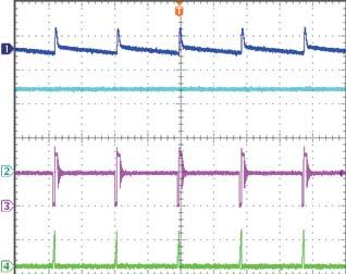
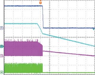
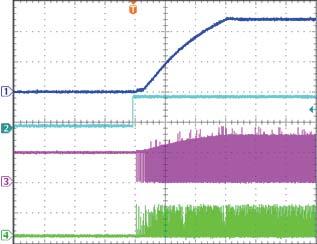
9 TYPICAL PERFORMANCE CHARACTERISTICS (continued) V IN = 48 V, V OUT = 12 V, I OUT = 1 A, Flyback mode, T A = 25 C, unless otherwise noted. MP6004 Rev

 V IN")


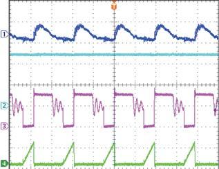
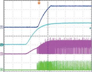
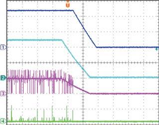
10 TYPICAL PERFORMANCE CHARACTERISTICS (continued) V IN = 48 V, V OUT = 12 V, I OUT = 1 A, Flyback mode, T A = 25 C, unless otherwise noted. MP6004 Rev
 V IN = 48 V, V OUT = 12 V, I OUT")

11 TYPICAL PERFORMANCE CHARACTERISTICS (continued) V IN = 48 V, V OUT = 12 V, I OUT = 1 A, Flyback mode, T A = 25 C, unless otherwise noted. MP6004 Rev
12 PIN FUNCTIONS PIN# Name Description 1, 2 GND Switching converter power return. 3 EN Regulator on/off control input. EN can program UVLO start-up through a Zener diode and a resistor divider. 4,12 NC No connection. NC is not connected internally. Float NC or connect to GND in layout. 5 Positive power supply terminal. 6 FB2 Feedback for non-isolated buck solution. Connect FB2 to in flyback application. 7 MODE Buck mode or flyback mode select pin. MODE is pulled up internally to VCC through a 1.5 µa current source. Float MODE for buck application mode; connect MODE to GND for flyback application mode. 8 FB1 Feedback for flyback solution. Connect FB1 to GND in buck application. 9 ILIM IC switching current limit program pin. Connect ILIM to GND through a resistor to program the peak current limit. 10 AGND Analog power return for switching converter control circuit. 11 VCC Supply bias voltage pin, powered through internal LDO from. It is recommended to connect a capacitor (no less than 1 µf) between VCC and GND. 13,14 SW Drain of converter switching MOSFET. MP6004 Rev
13 FUNCTION DIAGRAM High-Voltage LDO VCC VAUX EN /VCC UVLO VOUT FB1 DCM Detection SW Feedback Sampling Control & Driver Management VAUX FB2 Protection Current Sense AGND ILIMIT Program GND MODE ILIM Figure 1 Functional block diagram MP6004 Rev
14 OPERATION Start-Up and Power Supply MP6004 features an 80 V start-up circuit. When V IN is higher than 4.3 V, the capacitor at VCC is charged through the internal LDO. Normally V CC is regulated at 5.4 V (if is high enough), and the V CC UVLO is 4.7 V, typically. With the exception of V CC UVLO, the MP6004 has an additional 11.6 V V IN UVLO. When V IN is higher than the 11.6 V UVLO, V CC is charged higher than the 4.7 V UVLO, and EN pin is high, MP6004 starts switching. V CC can be powered from the transformer auxiliary winding to save IC power loss. Refer to the Vcc Power Supply Setting section on page 18 for more details. Flyback and Buck Mode MP6004 supports both flyback and buck topology applications. Connect MODE to GND to set the MP6004 in flyback mode, and float MODE to set the MP6004 in buck mode. MODE is pulled up internally to V CC through a 1.5 µa current source. Do not connect MODE to V IN in buck mode, and do not place a resistor between MODE and GND in flyback mode. Switching Work Principle After start-up, MP6004 works in discontinuous conduction mode (DCM). The second switching cycle will not start until the inductor current drops to 0 A. In each cycle, the internal MOSFET is turned on, and the current-sense circuit senses the current I P(t) internally. Use Equation (1) to calculate the rate at which the current rises linearly in flyback mode: di dt p(t) V IN = (1) LM When I P(t) rises up to I PK, the internal MOSFET turns off (see Figure 2). The energy stored in the primary-side inductance transfers to the secondary-side through the transformer. Figure 2 Primary-side current waveform The primary-side inductance (L M ) stores energy in each cycle as a function of Equation (2): 1 2 E= LMPK I (2) 2 Calculate the power transferred from the input to the output with Equation (3): 1 2 P = LMPK I FS (3) 2 Where F S is the switching frequency. When I PK is constant, the output power depends on F S and L M. Use Equation (4) to calculate the rate at which the current rises linearly in buck mode: dip(t) VOUT = (4) dt L M The internal MOSFET turns off when I P(t) rises to I PK (see Figure 3). The output current is calculated with Equation (5): I OUT 1 = DIPK (5) 2 Where, D is the inductor current conducting duty cycle. Figure 3 Inductor current waveform MP6004 Rev
15 Light-Load Control In flyback mode (if the load decreases), MP6004 stretches down the frequency automatically to reduce the power transferring while keeping the same I PK in each cycle. An approximate 10 khz minimum frequency is applied to detect the output voltage even at a very light load. During this condition, the switching I PK jumps between 20 percent of the normal I PK and 100 percent of the normal I PK to reduce the power transferring. The MP6004 still transfers some energy to the output even if there is no load on the output due to the 10 khz minimum frequency. This means that some load is required to maintain the output voltage, or else V OUT will rise and trigger an OVP. In buck mode, the MP6004 has no minimum frequency limit, so it stretches down to a very low frequency and regulates the output automatically even there is no load on the output. Frequency Control By monitoring the auxiliary winding voltage in flyback mode or monitoring the SW voltage in buck mode, the MP6004 detects and regulates the inductor current in DCM. The frequency is controlled by the peak current, the current ramp slew rate, and the load current. The maximum frequency occurs when the MP6004 runs in critical conduction mode, providing the maximum load power. The MP6004 switching frequency should be lower than 200 khz in the design. Voltage Control In flyback application, the MP6004 detects the auxiliary winding voltage from FB1 during the secondary-side diode conduction period. Assume the secondary winding is the master, and the auxiliary winding is the slave. When the secondary-side diode conducts, the FB1 voltage is calculated with Equation (6): N V = (V + V ) R A 2 FB1 OUT D1F NS R1+ R2 Where: V D1F is the output diode forward-drop voltage. V OUT is the output voltage. (6) N A and N S are the turns of the auxiliary winding and the secondary-side winding, respectively. R1 and R2 are the resistor dividers for sampling. The output voltage differs from the secondarywinding voltage due to the current-dependant diode forward voltage drop. If the secondarywinding voltage is always detected at a fixed secondary current, the difference between the output voltage and the secondary-winding voltage is a fixed V D1F. MP6004 starts sampling the auxiliary-winding voltage after the internal power MOSFET turns off for 0.7 μs and finishes the sampling after the secondary-side diode conducts for 3 μs. This provides good regulation when the load changes. However, the secondary diode conducting period must be longer than 3 μs in each cycle, and the FB1 signal must be smooth 0.7 μs after the switch turns off. With a buck solution, there is one FB2 pin referenced to. It can be used as the reference voltage for the buck application. The output voltage is referenced to and does not have the same GND as the input power. Programming the Current Limit The MP6004 current limit is set by an external resistor (R3) from ILIM to ground. The value of R3 can be estimated with Equation (7): I 100 R3 V 0.18 L L LIM = + (7) Where I LIM is the current limit in A, V L is the voltage applied on the inductor when the MOSFET turns on, R3 is the setting resistor in kω, and L is the inductor in μh. The current limit cannot be programmed higher than 3 A. Leading-Edge Blanking Transformer parasitic capacitance induces a current spike on the sense resistor when the power switch turns on. The MP6004 includes a 450 ns leading-edge blanking period to avoid falsely terminating the switching pulse. During this blanking period, the current sense comparator is disabled, and the gate driver cannot switch off. MP6004 Rev
16 DCM Detection The MP6004 regulator operates in discontinuous conduction mode in both flyback and buck modes. In flyback mode, the MP6004 detects the falling edge of the FB1 voltage in each cycle. The second cycle switching will not start unless the chip detects a 50 mv falling edge on FB1. In buck mode, the MP6004 detects the falling edge of the SW voltage in each cycle. The second cycle switching will not start unless the chip detects 0.14 V falling edge between V SW -V IN. Over-Voltage & Open-Circuit Protection In flyback mode, the MP6004 includes overvoltage protection (OVP) and open-circuit protection. If the voltage at FB1 exceeds 125 percent of V REF1 (or FB1 s -60 mv falling edge cannot be detected because the feedback resistor is removed), immediately the MP6004 shuts off the driving signal and enters hiccup mode by re-charging the internal capacitor. The MP6004 resumes normal operation when the fault is removed. In buck mode, if the voltage at FB2 is higher than the reference voltage, the MP6004 stops switching immediately. Over-Load Protection MP6004 will always work in DCM mode for any condition. In flyback mode, the secondary-side diode conduction duty cycle is limited to about 80 percent. In an over-load condition, the output energy is limited by I PK and F S. With a heavier load, the output drops and the diode conduction period becomes longer. This causes the switching frequency to drop so that the output energy can be limited. The MP6004 has same protection logic for an over-load/output-short condition. In buck mode, the duty cycle limitation does not apply, but the output current is limited to half of I PK. Thermal Shutdown When the junction temperature exceeds 150 C, the MP6004 shuts down. Once the temperature drops below 130 C, the part re-starts automatically. MP6004 Rev
17 APPLICATION INFORMATION EN Control Setting MP6004 turns on when EN goes high, and it turns off when EN goes low. EN is pulled low internally by an approximate 0.9 MΩ resistor. In flyback mode, the maximum on time is limited at about 8 μs. The secondary-side rectifier diode conduction time should be longer than 3 μs for FB1 feedback sampling. If V IN decreases and the inductor current cannot ramp the I PK to setting value within the maximum on time, the diode conduction time decreases to less than 3 μs, causing FB1 feedback sample failure. The MP6004 treats this failure as a V OUT drop and generates more pulses, causing V OUT to overshoot. In this condition, EN can be used to program V IN UVLO and shuts down the part before V IN drops (triggering the maximum on time). Since the EN high-level voltage is 3.9 V and the low-level voltage is 1.3 V, it is hard to program the V IN UVLO with a small hysteresis. In this condition, one resistor divider and one Zener diode is recommended (see Figure 4). Zener diode and resistor divider are recommended to set the appropriate V IN UVLO. There is an internal Zener diode on EN, which clamps the EN voltage to prevent runaway. The maximum pull-up current for the internal Zener clamp (assuming 6.5 V) should be less than 0.5 ma. If EN is driven with an external signal, use a signal voltage less than 6.5 V or connect EN to the signal through a pull-up resistor that ensures the maximum pull-up current is less than 0.5 ma. If using a resistor divider (see Figure 4) and V IN -V ZENER is higher than 6.5 V, the minimum resistance for the pull-up resistor R5 should be calculated with Equation (10): VZENER 6.5V 6.5V 0.5mA R5 V CC Power Supply Setting < (10) R6 The V CC voltage is charged through the internal LDO by. Normally, V CC is regulated at 5.4 V, typically. A capacitor no less than 1 µf is recommended for decoupling between V CC and GND. In flyback mode, V CC can be powered from the transformer auxiliary winding to save the highvoltage LDO power loss. Figure 4 UVLO setting with EN control For example, the MP6004 should be turned on before V IN rises to 36 V and shut down before V IN drops to 20 V. One 20 V Zener diode (D4) and a resistor divider (R5 = 100 kω/r6 = 49.9 kω) can be selected to program the V IN UVLO. The programmed V IN rising threshold can be calculated with Equation (8): 100kΩ+ 49.9kΩ _R < 20V + 3.9V = 31.7V 49.9kΩ The programmed V IN falling threshold is calculated with Equation (9): 100kΩ+ 49.9kΩ _F > 20V + 1.3V = 23.9V 49.9kΩ (8) (9) In buck mode, FB2 feedback is not affected by the rectifier diode conduction time, but the Figure 5 Supply V CC from auxiliary winding The auxiliary winding supply voltage can be calculated with Equation (11): N V = (V + V ) V (11) A CC OUT D1F D3F NS Where N A and N S are the turns of the auxiliary winding and the output winding, V D1F is the output rectifier diode voltage drop, and V D3F is the D3 voltage drop in Figure 5. V CC voltage is clamped at about 6.2 V by one internal Zener diode. The clamp current MP6004 Rev
18 capability is about 1.2 ma. If the auxiliary winding power voltage is higher than 6.2 V (especially in a heavy-load condition), a series resistor (R8) is necessary to limit the current to VCC. For simple application, supply the V CC power through the internal LDO directly. Output Voltage Setting In MP6004, there are two feedback pins for different application modes. In flyback mode, the converter detects the auxiliary winding voltage from FB1. R1 and R2 are the resistor dividers for the feedback sampling (see Figure 6). FB1 GND R2 R1 Na Figure 6 Feedback in isolation application When the primary-side power MOSFET turns off, the auxiliary-winding voltage is sampled. The output voltage is estimated with Equation (12): V V (R + R ) REF1 1 2 S OUT = VD1F (12) R2 NA Where, N S is the transformer secondary-side winding turns. N A is the transformer auxiliary winding turns. V D1F is the rectifier diode forward drop. V REF1 is the reference voltage of FB1 (1.99 V, typically). When the primary-side power MOSFET turns on, the auxiliary winding forces a negative voltage to FB1. The FB1 voltage is clamped to less than -0.7 V internally, but the clamp current should be limited to less than -0.5 ma by R1. For example, if the auxiliary winding forces -11 V to R1 (to make the current flowing from FB1 to R1 lower than -0.5 ma), R1 resistance must be higher than 22 kω (if ignoring R2 current). N Generally, select R2 with a 10 kω to 50 kω resistor to limit noise and provide an appropriate R1 for the -0.5 ma negative current limit. In buck application, the feedback pin is FB2. The output voltage can be estimated with Equation (13): V R + R 1 2 OUT = VREF2 (13) R2 Where, V REF2 is the reference voltage of FB V, typically. Maximum Switching Frequency When MP6004 works in DCM, the frequency reaches its maximum value during a full-load condition. The maximum frequency is affected by the peak current limit, the inductance, and the input/output voltage. Generally, design the maximum frequency lower than 200 khz. In buck mode, the maximum frequency occurs when the buck runs in critical conduction mode. The frequency can be calculated with Equation (14): F SW _ MAX (V V ) V = I L V IN OUT OUT LIM IN (14) Where, I LIM is the I PK set by the current limit resistor. With a lighter load, the frequency is lower than the maximum frequency above. In flyback mode, design the maximum frequency with the minimum input voltage and the maximum load condition. Calculate the frequency with Equation (15): F SW 1 T + T + T ON CON DELAY Where: T ON is the MOSFET one pulse turn-on time determined with Equation (16): T I L (15) LIM M ON = (16) L M is the transformer primary-winding inductance. MP6004 Rev
19 T CON is the rectifier diode current conducting time and can be calculated with Equation (17): NS ILIM LM TCON = (17) N P (VOUT + V D1F) Where, N S is the transformer secondary-side winding turns.n P is the transformer primary-side winding turns. T DELAY is the resonant delay time from the rectifier diode current drop to 0 A to the auxiliary-winding voltage drop to 0 V. The resonant time can be tested on the board (estimate around 0.5 μs). In flyback mode, the MP6004 samples the feedback signal within 3 μs after the primaryside MOSFET turns off. The secondary-side diode conduction time in Equation (17) should be higher than 3 μs. This time period, combined with the duty cycle, determines the maximum frequency. Input Capacitor Selection An input capacitor is required to supply the AC ripple current to the inductor while limiting noise at the input source. A low ESR capacitor is required to keep the noise to the IC at a minimum. Ceramic capacitors are preferred, but tantalum or low ESR electrolytic capacitors will suffice. For ceramic capacitors, the capacitance dominates the impedance at the switching frequency. The ripple will be the worst at light load. The required input capacitance can be estimated with Equation (18): 0.5 ILIM TON C1 = (18) P _ P Where C 1 is the input capacitor value, V INP-P is the expected input ripple, and T ON is the MOSFET turn-on time. In an isolated application, T ON is calculated with Equation (19): ILIM LM TON = (19) In a non-isolation application, T ON is calculated with Equation (20): ILIM L TON = (20) VOUT Where L is the buck`s inductor value. Output Capacitor Selection The output capacitor maintains the DC output voltage. For best results, use ceramic capacitors or low ESR capacitors to minimize the output voltage ripple. For ceramic capacitors, the capacitance dominates the impedance at the switching frequency. In flyback application, the worst output ripple occurs under a light-load condition; the worst output ripple can be estimated by Equation (21): V OUTP _P 0.5 N I T = N C2 P LIM CON Where, C2 is the output capacitor value. V OUTP-P is the output ripple. S (21) Normally, a 44 μf or higher ceramic capacitor is recommended as the output capacitor. This allows a small Vo ripple and stable operation. In buck application, the worst Vout ripple can be estimated with Equation (22): V OUTP _ P ILIM L ( + V D1F ) = C2 (V V ) (V + V ) IN OUT OUT D1F (22) Leakage Inductance The transformer s leakage inductance decreases system efficiency and affects the output current and voltage precision. Optimize the transformer structure to minimize the leakage inductance. Aim for a leakage inductance less than 3 percent of the primarywinding inductance. RCD Snubber for Flyback The transformer leakage inductance causes spikes and excessive ringing on the MOSFET drain voltage waveform, affecting the output voltage sampling 0.7 µs after the MOSFET turns off. The RCD snubber circuit limits the SW voltage spike (see Figure 7). Figure 7 RCD snubber MP6004 Rev
20 The power dissipation in the snubber circuit is estimated with Equation (23): 1 2 PSN = LK ILIM F (23) S 2 Where, L K is the leakage inductance. Since R4 consumes the majority of the power, R4 is estimated with Equation (24): 2 VSN R4 = (24) P SN Where, V SN is the expected snubber voltage on C4. The snubber capacitor C4 can be designed to get appropriate voltage ripple on the snubber using Equation (25): VSN Δ VSN = R4 C4 F S (25) Generally, a 15 percent ripple is acceptable. Buck Inductor Selection The inductor is required to transfer the energy between the input source and the output capacitors. Unlike normal application where inductors determine the inductor ripple, the MP6004 always works in DCM while V IN, V OUT, and I LIM are constant. The inductor only determines the speed of the current rising and falling, which determines the switching period. The expected maximum frequency can determine the inductor value using Equation (26): L (V V ) (V + V ) 1 IN OUT OUT D1F ( + V D1F ) IPEAK FSW (26) F SW is the expected maximum switching frequency, which should be lower than 200 khz in general setting. Output Diode Selection The output rectifier diode supplies current to the output capacitor when the internal MOSFET is off. Use a Schottky diode to reduce loss due to the diode forward voltage and recovery time. In isolation application, the diode should be rated for a reverse voltage greater than Equation (27): V N V V V = + + (27) IN S D1 OUT PD1 NP V PD1 can be selected at 40 percent ~100 percent of V OUT + V IN x N S /N P. An RC or RCD snubber circuit for the output diode D1 is recommended. In buck mode, the diode reverse voltage equates to the input voltage. A 20 percent ~ 40 percent margin is recommended. In both applications, the current rating should be higher than the maximum output current. Dummy Load When the system operates without a load in flyback mode, the output voltage rises above the normal operation voltage because of the minimum switching frequency limitation. Use a dummy load for good load regulation. A large dummy load decreases efficiency, so the dummy load is a tradeoff between efficiency and load regulation. For applications using Figure 10, a minimum load of around 10 ma is recommended. PCB Layout Guidelines Efficient PCB layout for high-frequency switching power supplies is critical. Poor layout may result in reduced performance, excessive EMI, resistive loss, and system instability. For best results, refer to Figure 8 and Figure 9 and follow the guidelines below: For flyback application: 1. Keep the input loop as short as possible between the input capacitor, transformer, SW, and GND plane for minimal noise and ringing. 2. Keep the output loop between the rectifier diode, the output capacitor, and the transformer as short as possible. 3. Keep the clamp loop circuit between D2, C4, and the transformer as small as possible. 4. Place the VCC capacitor close to VCC for the best decoupling. The current setting resistor R3 should be placed as close to ILIM and AGND as possible. 5. Keep the feedback trace far away from noise sources (such as SW). The trace connecting FB1 should be short. MP6004 Rev
21 MP6004 PRIMARY-SIDE REGULATED FLYBACK/BUCK 80V DCDC CONVERTER 6. Use a single point connection between power GND and signal GND. Vias around GND and the thermal pad are recommended to lower the die temperature. Top Layer Bottom Layer Via VOUTGND Figure 8 Recommended flyback layout For buck application: 1. Keep the input loop as short as possible between the input capacitor, rectifier diode, SW, and GND plane for minimal noise and ringing. 2. Keep the output loop between the rectifier diode, the output capacitor, and the inductor as short as possible. 3. Place the VCC capacitor close to VCC for the best decoupling. The current setting resistor R3 should be placed as close to ILIM and AGND as possible. 4. Connect the output voltage sense and power supply from the output capacitor with parallel traces. The feedback trace should be far away from noise sources (such as SW). The trace connected to FB2 should be short. 5. Use a single point connection between power GND and signal GND. Vias around GND and the thermal pad are recommended to lower the die temperature. VOUT Figure 9 Recommended buck layout GND Design Example Table 1 shows a design example following the application guidelines for the following specifications in flyback applications: Table 1 Flyback design example V IN V OUT I OUT 36 V-72 V 12 V 0 A-1 A The typical application circuit for V OUT = 12 V in Figure 10 shows the detailed application schematic and is the basis for the typical performance waveforms. For more detailed device applications, please refer to the related evaluation board datasheet. Table 2 shows a design example following the application guidelines for the following specifications in buck applications: Table 2 Buck design example V IN V OUT I OUT 36 V-72 V 12 V 0 A-1 A The typical application circuit is shown in Figure 11. For more detailed device applications, please refer to the related evaluation board datasheet. MP6004 Rev
22 TYPICAL APPLICATION CIRCUITS 36 V-72 V D4 20 V R5 100 k PGND C1B 47 µf C1A 2.2 µf FB2 R4 10 k D2 200 V C4 10 nf PGND Np1 Np2 T1 Ns D1 SBR8U60P5 C5 R7 1 nf 20Ω C2A 22 µf C2B 22 µf 12 V@1 A C2C 220 µf VOUT GND R k C3 1 µf R k PGND PGND VCC PGND EN SW U1 VCC FB1 MP6004 ILIM MODE AGND GND R k R2 20 k D3 R8 1 k VCC AGND C6 1nF/2000 V AGND VOUTGND PGND PGND PGND AGND Figure 10 Flyback application circuit, V IN = 36 V-72 V, V OUT = 12 V, I OUT =1 A FB2 Figure 11 Buck application circuit, V IN = 36 V-72 V, V OUT = 12 V, I OUT = 1 A 20 V 2.2 µf 47 µf 20 k 22 µf 100 µf 100 k GND 33 k L1 10 µh EN SW 49.9 k 1 µf VCC ILIM MP6004 FB1 MODE GND 43.2 k AGND GND GND GND GND GND Figure 12 Buck application circuit, V IN = 36 V-72 V, V OUT = 5 V, I OUT = 1 A MP6004 Rev
23 PACKAGE INFORMATION QFN-14 (3mm X 3mm) PIN 1 ID MARKING PIN 1 ID SEE DETAIL A PIN 1 ID INDEX AREA TOP VIEW BOTTOM VIEW PIN 1 ID OPTION A 0.30x45 TYP. PIN 1 ID OPTION B R0.20 TYP. SIDE VIEW DETAIL A NOTE: 1) ALL DIMENSIONS ARE IN MILLIMETERS. 2) EXPOSED PADDLE SIZE DOES NOT INCLUDE MOLD FLASH. 3) LEAD COPLANARITY SHALL BE 0.10 MILLIMETERS MAX. 4) JEDEC REFERENCE IS MO ) DRAWING IS NOT TO SCALE. RECOMMENDED LAND PATTERN NOTICE: The information in this document is subject to change without notice. Users should warrant and guarantee that third party Intellectual Property rights are not infringed upon when integrating MPS products into any application. MPS will not assume any legal responsibility for any said applications. MP6004 Rev
MP5090 Low I Q, Dual-Channel, 3A/2A Load Switch
 MP5090 Low I Q, Dual-Channel, 3A/2A Load Switch The Future of Analog IC Technology DESCRIPTION The MP5090 integrates dual load switches to provide load protection covering a 0.5V to 5.5V voltage range.
MP A, 50V, 1.2MHz Step-Down Converter in a TSOT23-6
 MP2456 0.5A, 50V, 1.2MHz Step-Down Converter in a TSOT23-6 DESCRIPTION The MP2456 is a monolithic, step-down, switchmode converter with a built-in power MOSFET. It achieves a 0.5A peak-output current over
MPM V-5.5V, 4A, Power Module, Synchronous Step-Down Converter with Integrated Inductor
 The Future of Analog IC Technology MPM3840 2.8V-5.5V, 4A, Power Module, Synchronous Step-Down Converter with Integrated Inductor DESCRIPTION The MPM3840 is a DC/DC module that includes a monolithic, step-down,
MP2131 High Efficiency, 4 A, 5.5 V, 1.2 MHz Synchronous Step-Down Converter
 The Future of Analog IC Technology MP2131 High Efficiency, 4 A, 5.5 V, 1.2 MHz Synchronous Step-Down Converter DESCRIPTION The MP2131 is a monolithic step-down, switchmode converter with built-in internal
MP8007 Fully-Integrated 802.3af-Compatible PoE PD Interface with 13W Primary-side Regulated Flyback or Buck Converter
 The Future of Analog IC Technology DESCRIPTION The MP8007 is an integrated IEEE 802.3af compatible PoE Powered Device with PD interface and power converter. It is targeted for isolated or non-isolated
MP6902 Fast Turn-off Intelligent Controller
 MP6902 Fast Turn-off Intelligent Controller The Future of Analog IC Technology DESCRIPTION The MP6902 is a Low-Drop Diode Emulator IC for Flyback converters which combined with an external switch replaces
MP V, 4A Synchronous Step-Down Coverter
 MP9151 20, 4A Synchronous Step-Down Coverter DESCRIPTION The MP9151 is a synchronous rectified stepdown switch mode converter with built in internal power MOSFETs. It offers a very compact solution to
MP A, 55V, 100kHz Step-Down Converter with Programmable Output OVP Threshold
 The Future of Analog IC Technology MP24943 3A, 55V, 100kHz Step-Down Converter with Programmable Output OVP Threshold DESCRIPTION The MP24943 is a monolithic, step-down, switch-mode converter. It supplies
MPM3620A. 24 V/2 A DC/DC Module Synchronous Step-Down Converter with Integrated Inductor DESCRIPTION FEATURES APPLICATIONS TYPICAL APPLICATION
 The Future of Analog IC Technology MPM3620A 24 V/2 A DC/DC Module Synchronous Step-Down Converter with Integrated Inductor DESCRIPTION The MPM3620A is a synchronous, rectified, step-down module converter
MP2313 High Efficiency 1A, 24V, 2MHz Synchronous Step Down Converter
 The Future of Analog IC Technology MP2313 High Efficiency 1A, 24V, 2MHz Synchronous Step Down Converter DESCRIPTION The MP2313 is a high frequency synchronous rectified step-down switch mode converter
MP V, 7A, Low R DSON Load Switch With Programmable Current Limit
 The Future of Analog IC Technology MP5077 5.5V, 7A, Low R DSON Load Switch With Programmable DESCRIPTION The MP5077 provides up to 7A load protection over a 0.5V to 5.5V voltage range. With the small R
MP5410 Low Start-up Voltage Boost Converter with Four SPDT Switches
 The Future of Analog IC Technology DESCRIPTION The MP5410 is a high efficiency, current mode step-up converter with four single-pole/doublethrow (SPDT) switches designed for low-power bias supply application.
MP2314S 2A, 24V, 500kHz, High-Efficiency, Synchronous, Step-Down Converter
 The Future of Analog IC Technology DESCRIPTION The MP2314S is a high-efficiency, synchronous, rectified, step-down, switch mode converter with built-in, internal power MOSFETs. It is a next generation
MP A, 24V, 1.4MHz Step-Down White LED Driver
 MP2370 1.2A, 24V, 1.4MHz Step-Down White LED Driver DESCRIPTION The MP2370 is a monolithic step-down white LED driver with a built-in power MOSFET. It achieves 1.2A peak output current over a wide input
MPM V Input, 0.6A Module Synchronous Step-Down Converter with Integrated Inductor DESCRIPTION FEATURES APPLICATIONS
 The Future of Analog IC Technology MPM3805 6 Input, 0.6A Module Synchronous Step-Down Converter with Integrated Inductor DESCRIPTION The MPM3805 is a step-down module converter with built-in power MOSFETs
MP MHz, 700mA, Fixed-Frequency Step-Up Driver for up to 10 White LEDS
 MP3301 1.3MHz, 700mA, Fixed-Frequency Step-Up Driver for up to 10 White LEDS DESCRIPTION The MP3301 is a step-up converter designed to drive WLEDS arrays from a single-cell, lithium-ion battery. The MP3301
DESCRIPTION FEATURES APPLICATIONS TYPICAL APPLICATION
 MP5016 2.7V 22V, 1A 5A Current Limit Switch with Over Voltage Clamp and Reverse Block The Future of Analog IC Technology DESCRIPTION The MP5016 is a protection device designed to protect circuitry on the
1A, 6V, 1.5MHz, 17μA I Q, COT Synchronous Step Down Switcher In 8-pin TSOT23
 The Future of Analog IC Technology MP2159 1A, 6, 1.5MHz, 17μA I Q, COT Synchronous Step Down Switcher In 8-pin TSOT23 DESCRIPTION The MP2159 is a monolithic step-down switch mode converter with built-in
MP2494 2A, 55V, 100kHz Step-Down Converter
 The Future of Analog IC Technology MP2494 2A, 55V, 100kHz Step-Down Converter DESCRIPTION The MP2494 is a monolithic step-down switch mode converter. It achieves 2A continuous output current over a wide
MP28164 High-Efficiency, Single-Inductor, Buck-Boost Converter with 4.2A Switches
 The Future of Analog IC Technology MP28164 High-Efficiency, Single-Inductor, Buck-Boost Converter with 4.2A Switches DESCRIPTION The MP28164 is a high-efficiency, lowquiescent current, buck-boost converter
MP A, 24V, 1.4MHz Step-Down Converter
 The Future of Analog IC Technology DESCRIPTION The MP8368 is a monolithic step-down switch mode converter with a built-in internal power MOSFET. It achieves 1.8A continuous output current over a wide input
MP2225 High-Efficiency, 5A, 18V, 500kHz Synchronous, Step-Down Converter
 The Future of Analog IC Technology DESCRIPTION The MP2225 is a high-frequency, synchronous, rectified, step-down, switch-mode converter with built-in power MOSFETs. It offers a very compact solution to
MP A, 36V, 700KHz Step-Down Converter with Programmable Output Current Limit
 The Future of Analog IC Technology MP2490 1.5A, 36V, 700KHz Step-Down Converter with Programmable Output Current Limit DESCRIPTION The MP2490 is a monolithic step-down switch mode converter with a programmable
MP6909 Fast Turn-Off Intelligent Rectifier
 MP6909 Fast Turn-Off Intelligent Rectifier The Future of Analog IC Technology DESCRIPTION The MP6909 is a low-drop diode emulator IC that, when combined with an external switch, replaces Schottky diodes
MP1495 High Efficiency 3A, 16V, 500kHz Synchronous Step Down Converter
 The Future of Analog IC Technology DESCRIPTION The MP1495 is a high-frequency, synchronous, rectified, step-down, switch-mode converter with built-in power MOSFETs. It offers a very compact solution to
MP V - 21V, 0.8A, H-Bridge Motor Driver in a TSOT23-6
 The Future of Analog IC Technology MP6513 2.5V - 21V, 0.8A, H-Bridge Motor Driver in a TSOT23-6 DESCRIPTION The MP6513 is an H-bridge motor driver used for driving reversible motors, which can drive one
MP V to 5.5V Input, 1.2MHz, Dual-ch LCD Bias Power Supply
 MP5610 2.7V to 5.5V Input, 1.2MHz, Dual-ch LCD Bias Power Supply DESCRIPTION The MP5610 is a dual-output converter with 2.7V-to-5.5V input for small size LCD panel bias supply. It uses peak-current mode
MP2115 2A Synchronous Step-Down Converter with Programmable Input Current Limit
 The Future of Analog IC Technology DESCRIPTION The MP2115 is a high frequency, current mode, PWM step-down converter with integrated input current limit switch. The step-down converter integrates a main
MP A, 24V, 700KHz Step-Down Converter
 The Future of Analog IC Technology MP2371 1.8A, 24V, 700KHz Step-Down Converter DESCRIPTION The MP2371 is a monolithic step-down switch mode converter with a built-in internal power MOSFET. It achieves
MP2497-A 3A, 50V, 100kHz Step-Down Converter with Programmable Output OVP Threshold
 The Future of Analog IC Technology MP2497-A 3A, 50V, 100kHz Step-Down Converter with Programmable Output OVP Threshold DESCRIPTION The MP2497-A is a monolithic step-down switch mode converter with a programmable
MP2324 High Efficiency 2A, 24V, 500kHz Synchronous Step-Down Converter
 MP2324 High Efficiency 2A, 24V, 500kHz Synchronous Step-Down Converter DESCRIPTION The MP2324 is a high frequency synchronous rectified step-down switch mode converter with built in internal power MOSFETs.
MP2314 High Efficiency 2A, 24V, 500kHz Synchronous Step Down Converter
 The Future of Analog IC Technology MP2314 High Efficiency 2A, 24V, 500kHz Synchronous Step Down Converter DESCRIPTION The MP2314 is a high frequency synchronous rectified step-down switch mode converter
2A, 6V, 1.5MHz, 17μA I Q, COT Synchronous Step Down Switcher In 8-pin TSOT23
 The Future of Analog IC Technology DESCRIPTION The MP2161 is a monolithic step-down switch mode converter with built-in internal power MOSFETs. It achieves 2A continuous output current from a 2.5 to 6
MP2143 3A, 5.5V, 1.2MHz, 40μA I Q, COT Synchronous Step Down Switcher
 The Future of Analog IC Technology MP2143 3A, 5.5, 1.2MHz, 40μA I Q, COT Synchronous Step Down Switcher DESCRIPTION The MP2143 is a monolithic, step-down, switchmode converter with internal power MOSFETs.
MP6901 Fast Turn-off Intelligent Controller
 MP6901 Fast Turn-off Intelligent Controller The Future of Analog IC Technology DESCRIPTION The MP6901 is a Low-Drop Diode Emulator IC that, combined with an external switch replaces Schottky diodes in
MP V, 700kHz Synchronous Step-Up White LED Driver
 The Future of Analog IC Technology MP3306 30V, 700kHz Synchronous Step-Up White LED Driver DESCRIPTION The MP3306 is a step-up converter designed for driving white LEDs from 3V to 12V power supply. The
MP1496S High-Efficiency, 2A, 16V, 500kHz Synchronous, Step-Down Converter
 MP1496S High-Efficiency, 2A, 16, 500kHz Synchronous, Step-Down Converter DESCRIPTION The MP1496S is a high-frequency, synchronous, rectified, step-down, switch-mode converter with built-in power MOSFETs.
MP mA, 8-14V Input, LNB Power Supply and Control Voltage Regulator
 The Future of Analog IC Technology MP8125 550mA, 8-14V Input, LNB Power Supply and Control Voltage Regulator DESCRIPTION The MP8125 is a voltage regulator designed to provide efficient, low noise power
MP MHz, 350mA Boost Converter
 The Future of Analog IC Technology MP3209 1.4MHz, 350mA Boost Converter DESCRIPTION The MP3209 is a current mode step up converter intended for small, low power applications. The MP3209 switches at 1.4MHz
C2 47uF 10V GND. 3.3V/300mA VOUT GND
 1 9 1 7 MPQ4569-AEC1 75V, 0.3A Synchronous Step-Down Converter AEC-Q100 Qualified DESCRIPTION The MPQ4569 is a step-down switching regulator with integrated high-side/low-side, high-voltage power MOSFETs.
MPM3606A 21V/0.6A DC/DC Module Synchronous Step-Down Converter with Integrated Inductor
 MPM3606A 21V/0.6A DC/DC Module Synchronous Step-Down Converter with Integrated Inductor DESCRIPTION The MPM3606A is a synchronous rectified, step-down module converter with built-in power MOSFETs, inductor,
MP1496 High-Efficiency, 2A, 16V, 500kHz Synchronous, Step-Down Converter
 The Future of Analog IC Technology DESCRIPTION The MP1496 is a high-frequency, synchronous, rectified, step-down, switch-mode converter with built-in power MOSFETs. It offers a very compact solution to
MP20041 Dual, Ultra Low Noise, High PSRR 300mA Linear Regulator
 MP20041 Dual, Ultra Low Noise, High PSRR 300mA Linear Regulator DESCRIPTION The MP20041 is a dual-channel, micropower, ultra low noise, low dropout and high PSRR linear regulator. The output voltage of
MP V, 3.2A, H-Bridge Motor Driver
 MP6522 35V, 3.2A, H-Bridge Motor Driver DESCRIPTION The MP6522 is an H-bridge motor driver that operates from a supply voltage of up to 35V and delivers a peak motor current of up to 3.2A. The MP6522 is
MP4690 Smart Bypass For LED Open Protection
 The Future of Analog IC Technology DESCRIPTION The is a MOSFET based smart bypass for LED open protection, which provides a current bypass in the case of a single LED fails and becomes an open circuit.
MP8619 8A, 25V, 600kHz Synchronous Step-down Converter
 The Future of Analog IC Technology DESCRIPTION The MP8619 is a high frequency synchronous rectified step-down switch mode converter with built in internal power MOSFETs. It offers a very compact solution
MP2482 5A, 30V, 420kHz Step-Down Converter
 The Future of Analog IC Technology DESCRIPTION The MP2482 is a monolithic step-down switch mode converter with a built in internal power MOSFET. It achieves 5A continuous output current over a wide input
MPQ2454-AEC1 36V, 0.6A Step-Down Converter AEC-Q100 Qualified
 MPQ2454-AEC1 36V, 0.6A Step-Down Converter AEC-Q100 Qualified DESCRIPTION The MPQ2454 is a frequency-programmable (350kHz to 2.3MHz) step-down switching regulator with an integrated internal high-side,
MP Lamp, 36V Precision White LED Driver
 MP8 9 Lamp, V Precision White LED Driver The Future of Analog IC Technology DESCRIPTION The MP8 is a step-up converter designed for driving up to nine (9) series White LEDs (LED) from a single cell Lithium-Ion
MP2144 2A, 5.5V, 1.2MHz, 40μA I Q, COT Synchronous Step Down Switcher
 The Future of Analog IC Technology MP2144 2A, 5.5, 1.2MHz, 40μA I Q, COT Synchronous Step Down Switcher DESCRIPTION The MP2144 is a monolithic, step-down, switchmode converter with internal power MOSFETs.
MP kHz, 55V Input, 2A High Power LED Driver
 The Future of Analog IC Technology MP2488 200kHz, 55V Input, 2A High Power LED Driver DESCRIPTION The MP2488 is a fixed frequency step-down switching regulator to deliver a constant current of up to 2A
MP A, 55V, 480kHz Step-Down Converter in a TSOT23-6
 The Future of Analog IC Technology DESCRIPTION The MP2459 is a monolithic, step-down, switchmode converter with a built-in power MOSFET. It achieves a 0.5A peak-output current over a wide input supply
MP2671 Li-ion Battery Charger Protection Circuit
 The Future of Analog IC Technology MP2671 Li-ion Battery Charger Protection Circuit DESCRIPTION The MP2671 is a high-performance single cell Li-Ion/Li-Polymer battery charger protection circuit. By integrating
MP A,1MHz, Synchronous, Step-up Converter with Output Disconnect
 The Future of Analog IC Technology MP3414 1.8A,1MHz, Synchronous, Step-up Converter with Output Disconnect DESCRIPTION The MP3414 is a high-efficiency, synchronous, current mode, step-up converter with
MP9447 High-Efficiency, Fast-Transient, 5A, 36V Synchronous, Step-Down Converter
 MP9447 High-Efficiency, Fast-Transient, 5A, 36 Synchronous, Step-Down Converter DESCRIPTION The MP9447 is a fully-integrated, highfrequency, synchronous, rectified, step-down, switch-mode converter. It
MP A, 24V, 1.4MHz Step-Down White LED Driver
 The Future of Analog IC Technology DESCRIPTION The MP2370 is a monolithic step-down white LED driver with a built-in power MOSFET. It achieves 1.2A peak output current over a wide input supply range with
MP9943 High Efficiency 3A Peak, 36V, Synchronous Step-Down Converter With Power Good
 The Future of Analog IC Technology DESCRIPTION The MP9943 is a high-frequency, synchronous, rectified, step-down, switch-mode converter with built-in power MOSFETs. It offers a very compact solution to
SR A, 30V, 420KHz Step-Down Converter DESCRIPTION FEATURES APPLICATIONS TYPICAL APPLICATION
 SR2026 5A, 30V, 420KHz Step-Down Converter DESCRIPTION The SR2026 is a monolithic step-down switch mode converter with a built in internal power MOSFET. It achieves 5A continuous output current over a
MP A, 24V, 1.4MHz Step-Down Converter in a TSOT23-6
 The Future of Analog IC Technology MP2359 1.2A, 24V, 1.4MHz Step-Down Converter in a TSOT23-6 DESCRIPTION The MP2359 is a monolithic step-down switch mode converter with a built-in power MOSFET. It achieves
MPM3510A. 36V/1.2A Module Synchronous Step-Down Converter with Integrated Inductor DESCRIPTION FEATURES APPLICATIONS TYPICAL APPLICATION
 The Future of Analog IC Technology MPM351A 36V/1.2A Module Synchronous Step-Down Converter with Integrated Inductor DESCRIPTION The MPM351A is a synchronous, rectified, step-down converter with built-in
MP3356 High Voltage Photo Flash Charger and IGBT Driver for DSC
 The Future of Analog IC Technology MP3356 High Voltage Photo Flash Charger and IGBT Driver for DSC DESCRIPTION The MP3356 is a fast, highly efficient and precision high voltage photo-flash charger for
MP mA, 1.2MHz, Synchronous, Step-up Converter with Output Disconnect FEATURES DESCRIPTION
 The Future of Analog IC Technology MP3418 400mA, 1.2MHz, Synchronous, Step-up Converter with Output Disconnect DESCRIPTION The MP3418 is a high-efficiency, synchronous, current mode, step-up converter
MPM V Input 2A Module Synchronous Step-Down Converter with Integrated Inductor FEATURES DESCRIPTION APPLICATIONS TYPICAL APPLICATION
 The Future of Analog IC Technology DESCRIPTION The MPM3620 is a synchronous rectified, stepdown module converter with built-in power MOSFETs, inductor, and two capacitors. It offers a compact solution
MP4420 High Efficiency 2A, 36V, Synchronous Step Down Converter
 The Future of Analog IC Technology DESCRIPTION The MP4420 is a high-frequency, synchronous, rectified, step-down, switch-mode converter with built-in power MOSFETs. It offers a very compact solution to
MP KHz/1.3MHz Boost Converter with a 2A Switch
 The Future of Analog IC Technology DESCRIPTION The MP4 is a current mode step up converter with a A, 0.Ω internal switch to provide a highly efficient regulator with fast response. The MP4 can be operated
MP A Fixed Frequency White LED Driver
 The Future of Analog IC Technology DESCRIPTION The is a step-up converter designed for driving up to 39 white LEDs (13 strings of 3 LEDs each) from a 5V system rail. The uses a current mode, fixed frequency
MP A, 30V, 420kHz Step-Down Converter
 The Future of Analog IC Technology DESCRIPTION The MP28490 is a monolithic step-down switch mode converter with a built in internal power MOSFET. It achieves 5A continuous output current over a wide input
MPM V, 1.5A Module, Synchronous, Step-Down Converter with an Integrated Inductor AEC-Q100 Qualified
 The Future of Analog IC Technology DESCRIPTION The MPM3515 is a synchronous, rectified, stepdown converter with built-in power MOSFETs, inductors, and capacitors. The MPM3515 offers a very compact solution
MPQ20051-AEC1 Low Noise, High PSRR, 1A Linear Regulator AEC-Q100 Qualified
 MPQ20051-AEC1 Low Noise, High PSRR, 1A Linear Regulator AEC-Q100 Qualified DESCRIPTION The MPQ20051 is a low-dropout linear regulator that supplies up to 1A current with a 140mV dropout voltage. The externally-adjustable
NB634 High Efficiency 5A, 24V, 500kHz Synchronous Step-down Converter
 The Future of Analog IC Technology DESCRIPTION The NB634 is a high efficiency synchronous rectified step-down switch mode converter with built-in internal power MOSFETs. It offers a very compact solution
MPM3610A. 21V/1.2A DC/DC Module Synchronous Step-Down Converter with Integrated Inductor DESCRIPTION FEATURES APPLICATIONS TYPICAL APPLICATION
 The Future of Analog IC Technology DESCRIPTION The MPM361A is a synchronous rectified, step-down module converter with built-in power MOSFETs, inductor, and two capacitors. It offers a very compact solution,
MP2122 6V, 2A, Low Quiescent Current Dual, SYNC Buck Regulator
 The Future of Analog IC Technology MP2122 6V, 2A, Low Quiescent Current Dual, SYNC Buck Regulator DESCRIPTION The MP2122 is an internally-compensated, 1MHz fixed-frequency, dual PWM, synchronous, step-down
MP V Input, 1A, Step-Down Converter
 Efficiency(%) MP9486 100V Input, 1A, Step-Down Converter DESCRIPTION The MP9486 is a high-voltage, step-down, switching regulator that delivers up to 1A of continuous current to the load. It integrates
MP20142 Dual Channel, 200mA Linear Regulator With Programmable Output Voltage and Output Discharge
 The Future of Analog IC Technology MP20142 Dual Channel, 200mA Linear Regulator With Programmable Output Voltage and Output Discharge DESCRIPTION The MP20142 is a dual-channel, low noise, low dropout and
MP28200 Ultra-Low 500nA I q, High Efficiency, Wide Input 2V-5.5V, 1.5MHz, 200mA, Step-Down Regulator
 The Future of Analog IC Technology DESCRIPTION The MP28200 is a monolithic powermanagement unit containing 200mA, highefficiency, step-down, switching converters. The nanoamp quiescent current provides
MP V, 3A, 600kHz Synchronous Step-Down Converter
 The Future of Analog IC Technology DESCRIPTION The MP222 is an internally compensated 600kHz fixed frequency PWM synchronous step-down regulator. With a 3V to 6V bias supply (V CC ), MP222 operates from
MP156 Small, Energy-Efficient, Off-line Regulator 30mW No-Load Power Consumption
 The Future of Analog IC Technology MP156 Small, Energy-Efficient, Off-line Regulator 30mW No-Load Power Consumption DESCRIPTION MP156 is a primary-side regulator that provides accurate constant voltage
MP1484 3A, 18V, 340KHz Synchronous Rectified Step-Down Converter
 The Future of Analog IC Technology MP484 3A, 8, 340KHz Synchronous Rectified Step-Down Converter DESCRIPTION The MP484 is a monolithic synchronous buck regulator. The device integrates top and bottom 85mΩ
NB634 High Effeciency 5A, 24V, 500kHz Synchronous Step-down Converter
 The Future of Analog IC Technology NB634 High Effeciency 5A, 24, 500kHz Synchronous Step-down Converter DESCRIPTION The NB634 is a high frequency synchronous rectified step-down switch mode converter with
MP3115 High-Efficiency, Single-Cell Alkaline, 1.3MHz Synchronous Step-up Converter with Output Disconnect
 The Future of Analog IC Technology MP3115 High-Efficiency, Single-Cell Alkaline, 1.3MHz Synchronous Step-up Converter with Output Disconnect DESCRIPTION The MP3115 is a synchronous, fixed frequency, current
MP2315 High Efficiency 3A, 24V, 500kHz Synchronous Step Down Converter
 The Future of Analog IC Technology DESCRIPTION The MP2315 is a high frequency synchronous rectified step-down switch mode converter with built in internal power MOSFETs. It offers a very compact solution
MP2307 3A, 23V, 340KHz Synchronous Rectified Step-Down Converter
 The Future of Analog IC Technology TM TM MP307 3A, 3, 340KHz Synchronous Rectified Step-Down Converter DESCRIPTION The MP307 is a monolithic synchronous buck regulator. The device integrates 00mΩ MOSFETS
MP V-to-16V,1.2A, Single-Phase Brushless DC Motor Driver
 MP6510 4.5V-to-16V,1.2A, Single-Phase Brushless DC Motor Driver DESCRIPTION The MP6510 is a single-phase, brushless, DC motor driver with integrated power MOSFETs. It drives single-phase brushless DC motors.
MP2259 1A, 16V, 1.4MHz Step-Down Converter
 The Future of Analog IC Technology DESCRIPTION The MP9 is a monolithic integrated stepdown switch mode converter with an internal power MOSFET. It achieves A continuous output current over a wide input
MP9942. High Efficiency 2A, 36V, 410kHz Synchronous Step-Down Converter with Power Good DESCRIPTION FEATURES APPLICATIONS TYPICAL APPLICATION
 The Future of Analog IC Technology MP9942 High Efficiency 2A, 36V, 410kHz Synchronous Step-Down Converter with Power Good DESCRIPTION The MP9942 is a high-frequency, synchronous, rectified, step-down,
MP A, 27V Intelli-Phase TM Solution (Integrated HS/LS FETs and Driver) in a 5x5mm QFN
 in a 5x5mm QFN") The Future of Analog IC Technology MP8696 0A, 7V Intelli-Phase TM Solution (Integrated HS/LS FETs and Driver) in a 5x5mm QFN DESCRIPTION The MP8696 is a monolithic Half Bridge with built-in internal power
The Future of Analog IC Technology MP8696 0A, 7V Intelli-Phase TM Solution (Integrated HS/LS FETs and Driver) in a 5x5mm QFN DESCRIPTION The MP8696 is a monolithic Half Bridge with built-in internal power
36V, 1MHz, 0.6A Step-Down Converter With 35μA Quiescent Current VOUT 3.3V/0.6A
 The Future of Analog IC Technology MP4566 36, 1MHz, 0.6A Step-Down Converter With 35μA Quiescent Current DESCRIPTION The MP4566 is a high frequency (1MHz) stepdown switching regulator with integrated internal
EUP A,30V,500KHz Step-Down Converter DESCRIPTION FEATURES APPLICATIONS. Typical Application Circuit
 5A,30V,500KHz Step-Down Converter DESCRIPTION The is current mode, step-down switching regulator capable of driving 5A continuous load with excellent line and load regulation. The operates with an input
MP62130/MP V/5V, Single-Channel 500mA Current-Limited Power Distribution Switch with Output Discharge
 The Future of Analog IC Technology MP6230/MP623 3.3V/5V, Single-Channel 500mA Current-Limited Power Distribution Switch with Output Discharge DESCRIPTION The MP6230/MP623 Power Distribution Switch features
NOT RECOMMENDED FOR NEW DESIGNS REFER TO MP2147 MP Ultra Low Voltage, 4A, 5.5V Synchronous Step-Down Switching Regulator DESCRIPTION FEATURES
 The Future of Analog IC Technology DESCRIPTION The MP38115 is an internally compensated 1.5MHz fixed frequency PWM synchronous step-down regulator. MP38115 operates from a 1.1V to 5.5V input and generates
PACKAGE REFERENCE. ELECTRICAL CHARACTERISTICS V IN = 12V, T A = +25 C, unless otherwise noted.
 PACKAGE REFERENCE TOP VIEW TOP VIEW BST 1 SW BST 1 SW GND 2 5 GND 2 5 FB 3 EN FB 3 EN MP2259_PD01_TSOT23 MP2259_PD02_SOT23 Part Number* Package Temperature MP2259DJ TSOT23-0 C to 85 C * For Tape & Reel,
MP A, 15V, 800kHz Synchronous Buck Converter
 The Future of Analog IC Technology MP206.5A, 5, 800kHz Synchronous Buck Converter DESCRIPTION The MP206 is a.5a, 800kHz synchronous buck converter designed for low voltage applications requiring high efficiency.
MP1482 2A, 18V Synchronous Rectified Step-Down Converter
 The Future of Analog IC Technology MY MP48 A, 8 Synchronous Rectified Step-Down Converter DESCRIPTION The MP48 is a monolithic synchronous buck regulator. The device integrates two 30mΩ MOSFETs, and provides
MP A, 5.5V Synchronous Step-Down Switching Regulator
 The Future of Analog IC Technology DESCRIPTION The MP2120 is an internally compensated 1.5MHz fixed frequency PWM synchronous step-down regulator. MP2120 operates from a 2.7V to 5.5V input and generates
Monolithic Power Switcher for Off-line SMPS. Features
 General Description The consists of a primary side regulation controller and a high voltage transistor, and is specially designed for off-line power supplies within 1W output power. Typical applications
AT V,3A Synchronous Buck Converter
 FEATURES DESCRIPTION Wide 8V to 40V Operating Input Range Integrated 140mΩ Power MOSFET Switches Output Adjustable from 1V to 25V Up to 93% Efficiency Internal Soft-Start Stable with Low ESR Ceramic Output
MP4652 HIGH PERFORMANCE OFF-LINE TV LED DRIVER
 The Future of Analog IC Technology MP4652 HIGH PERFORMANCE OFF-LINE TV LED DRIVER DESCRIPTION The MP4652 is a high-performance, off-line LED driver designed to power LEDs for highpower isolated applications,
MP V, 5A Dual Channel Power Half-Bridge
 The Future of Analog IC Technology MP8046 28V, 5A Dual Channel Power Half-Bridge DESCRIPTION The MP8046 is a configurable full-bridge or dual channel half-bridge that can be configured as the output stage
CEP8101A Rev 1.0, Apr, 2014
 Wide-Input Sensorless CC/CV Step-Down DC/DC Converter FEATURES 42V Input Voltage Surge 40V Steady State Operation Up to 2.1A output current Output Voltage 2.5V to 10V Resistor Programmable Current Limit
MP2109 Dual 1.2MHz, 800mA Synchronous Step-Down Converter
 The Future of Analog IC Technology MP2109 Dual 1.2MHz, 800mA Synchronous Step-Down Converter DESCRIPTION The MP2109 contains two independent 1.2MHz constant frequency, current mode, PWM step-down converters.