MPM3610A. 21V/1.2A DC/DC Module Synchronous Step-Down Converter with Integrated Inductor DESCRIPTION FEATURES APPLICATIONS TYPICAL APPLICATION
|
|
|
- Godwin Jordan
- 6 years ago
- Views:
Transcription
1 The Future of Analog IC Technology DESCRIPTION The MPM361A is a synchronous rectified, step-down module converter with built-in power MOSFETs, inductor, and two capacitors. It offers a very compact solution, requires only 5 external components to achieve a 1.2A continuous output current with excellent load and line regulation over a wide input supply range and provides fast load transient response. Full protection features include over-current protection and thermal shut-down. MPM361A eliminates design and manufacturing risks while dramatically improving time-to-market. The MPM361A is available in a space-saving QFN2 (3mmx5mmx1.6mm) package. MPM361A 21V/1.2A DC/DC Module Synchronous Step-Down Converter with Integrated Inductor FEATURES 4.5V-to-21V Operating Input Range 1.2A Continuous Load Current 9mΩ/4mΩ Low R DS(ON) Internal Power MOSFETs Integrated Inductor Integrated VCC and Bootstrap Capacitors Power Save Mode at Light Load Power Good Indicator OCP Protection and Hiccup Thermal Shutdown Output Adjustable from.8v Available in QFN2 (3x5x1.6mm) Package Total solution size 6.7mm x7.3mm APPLICATIONS Industrial Controls Medical and Imaging Equipment Telecom and Networking Applications LDO Replacement Space and Resource-limited Applications All MPS parts are lead-free and adhere to the RoHS directive. For MPS green status, please visit MPS website under Products, Quality Assurance page. MPS and The Future of Analog IC Technology are registered trademarks of Monolithic Power Systems, Inc. TYPICAL APPLICATION MPM361A Rev
2 ORDERING INFORMATION Part Number* Package Top Marking MPM361AGQV QFN-2 (3mmx5mmx1.6mm) See Below * For Tape & Reel, add suffix Z (e.g. MPM361AGQV Z); TOP MARKING MP: MPS prefix: Y: year code; W: week code: 361A: first five digits of the part number; LLL: lot number; M: module; MPM361A Rev
3 PACKAGE REFERENCE ABSOLUTE MAXIMUM RATINGS (1) V IN V to 28V V SW V (-5V for <1ns) to 28V (3V for <1ns) V BST... V SW +6V All Other Pins V to 6V (2) Continuous Power Dissipation (T A = +25 C) (3) W Junction Temperature C Lead Temperature C Storage Temperature C to 15 C Recommended Operating Conditions (4) Supply Voltage V IN V to 21V Output Voltage....8V to V IN *D MAX (5) Operating Junction Temp. (T J ). -4 C to +125 C Thermal Resistance (6) θ JA θ JC QFN-2 (3mmx5mmx1.6mm) C/W Notes: 1) Exceeding these ratings may damage the device. 2) About the details of EN pin s ABS MAX rating, please refer to page 14, Enable control section. 3) The maximum allowable power dissipation is a function of the maximum junction temperature T J (MAX), the junction-toambient thermal resistance θ JA, and the ambient temperature T A. The maximum allowable continuous power dissipation at any ambient temperature is calculated by P D (MAX) = (T J (MAX)-T A)/θ JA. Exceeding the maximum allowable power dissipation will cause excessive die temperature, and the regulator will go into thermal shutdown. Internal thermal shutdown circuitry protects the device from permanent damage. 4) The device is not guaranteed to function outside of its operating conditions. 5) In practical design, the minimum is limited by minimum on time, 5ns on time is commonly recommended for calculating to give some margin. For output voltage setting above 5.5V, please refer to the application information on page 17. 6) Measured on JESD51-7, 4-layer PCB. MPM361A Rev
4 ELECTRICAL CHARACTERISTICS Vin=12V, T J =-4 C to +125 C (7), typical value is tested at T J =+25 C, unless otherwise noted. Parameter Symbol Condition Min Typ Max Units Supply Current (Shutdown) Supply Current (Quiescent) I s I q VEN = V, T J =+25 C μa VEN = V, T J =-4 C to +125 C μa V FB = 1V, T J =+25 C.3.39 ma V FB = 1V, T J =-4 C to +125 C.3.44 ma HS Switch-On Resistance HS RDS-ON V BST-SW =5V 9 mω LS Switch-On Resistance LS RDS-ON V CC =5V 4 mω Inductor DC Resistance L DCR 6 mω Switch Leakage SW LKG V EN = V, V SW =12V 1 μa Current Limit I LIMIT Under 4% Duty Cycle A Oscillator Frequency f SW V FB =.75V, T J =+25 C khz V FB =.75V, T J =-4 C to +125 C khz Fold-Back Frequency f FB V FB =2mV.3 f SW V FB =7mV, T J =+25 C % Maximum Duty Cycle D MAX V FB =7mV, T J =-4 C to +125 C % Minimum On Time (8) τ ON _MIN 3 ns Feedback Voltage V FB T J =25 C mv T J =-4 C to +125 C mv Feedback Current I FB V FB =82mV 1 5 na EN Rising Threshold VEN_RISING T J =+25 C V T J =-4 C to +125 C V EN Falling Threshold EN Input Current VEN_FALLING IEN T J =+25 C V T J =-4 C to +125 C V VEN=2V, T J =+25 C μa VEN=2V, T J =-4 C to +125 C μa Power Good Rising Threshold PG VTH-Hi T J =+25 C V FB Power Good Falling Threshold PG VTH-LO T J =+25 C V FB Power Good Rising Delay PG TD_RSING T J =+25 C µs T J =-4 C to +125 C µs Power Good Falling Delay PG TD_FALLING T J =+25 C µs Power Good Sink Current Capability T J =-4 C to +125 C µs V PG Sink 1mA.4 V Power Good Leakage Current I PG-LEAK V PG =6V 1 μa MPM361A Rev
5 ELECTRICAL CHARACTERISTICS(continued) Vin=12V, T J =-4 C to +125 C, typical value is tested at T J =+25 C, unless otherwise noted. Parameter Symbol Condition Min Typ Max Units VIN Under-Voltage Lockout Threshold Rising VIN Under-Voltage Lockout Threshold Hysteresis VCC Regulator INUV Vth T J =+25 C V T J =-4 C to +125 C V INUV HYS mv V CC T J =+25 C V T J =-4 C to +125 C V VCC Load Regulation I CC =5mA % Soft-Start Time t SS from 1% to 9%, T J =+25 C ms from 1% to 9%, T J =-4 C to +125 C ms Thermal Shutdown (8) T SD 15 C Thermal Hysteresis (8) T SD_HYS 2 C Notes: 7) Not tested in production. Guaranteed by over-temperature correlation. 8) Guaranteed by Characterization. MPM361A Rev
6 TYPICAL CHARACTERISTICS V IN = 12V, = 3.3V, T A = 25 C, unless otherwise noted MPM361A Rev
7 TYPICAL CHARACTERISTICS (continued) V IN = 12V, = 3.3V, T A = 25 C, unless otherwise noted , 1, 1, 1,, MPM361A Rev
 V IN = 12V, = 3.")

8 TYPICAL CHARACTERISTICS (continued) V IN = 12V, = 3.3V, T A = 25 C, unless otherwise noted. MPM361A Rev


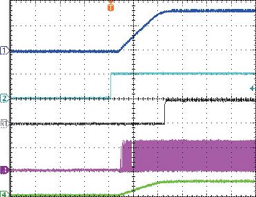
9 TYPICAL PERFORMANCE CHARACTERISTICS Performance waveforms are captured from the evaluation board discussed in the Design Example section.v IN = 12V, = 3.3V, T A = 25 C, unless otherwise noted. /AC 1mV/div. V IN /AC 5mV/div. V SW 1V/div. 1A/div. /AC 2mV/div. V IN /AC 1mV/div. V SW 1V/div. 2A/div. 2V/div. V PG 5V/div. V IN 1V/div. V SW 1V/div. 2A/div. 2V/div. V PG 5V/div. V IN 1V/div. V SW 1V/div. 2A/div. 2V/div. V PG 5V/div. V IN 1V/div. V SW 1V/div. 5mA/div. 2V/div. V PG 5V/div. V IN 1V/div. V SW 1V/div. 1A/div. 2V/div. 2V/div. 2V/div. V PG 5V/div. V EN 5V/div. V PG 5V/div. V SW 1V/div. 2A/div. V EN 5V/div. V PG 5V/div. V SW 1V/div. 2A/div. V EN 5V/div. V SW 1V/div. 2A/div. MPM361A Rev
 Performance waveforms are")


10 TYPICAL PERFORMANCE CHARACTERISTICS (continued) Performance waveforms are captured from the evaluation board discussed in the Design Example section.v IN = 12V, = 3.3V, T A = 25 C, unless otherwise noted. MPM361A Rev
11 PIN FUNCTIONS Package Pin # Name 1 FB 2 VCC 3 AGND Description Feedback. Connect to the tap of an external resistor divider from the output to AGND to set the output voltage. The frequency fold-back comparator lowers the oscillator frequency when the FB voltage is below 4mV to prevent current limit runaway during a short circuit fault. Place the resistor divider as close to the FB pin as possible. Avoid placing vias on the FB traces. Internal 5V LDO output. Internal circuit integrates LDO output capacitor, so there is no need to add external capacitor. Analog Ground. Reference ground of logic circuit. AGND is internally connected to PGND. There is no need to add external connections to PGND. 4, 5, 6 SW Switch Output. Large copper plane is recommended on pin 4, 5 and 6 for better heat sink. 7, 8, 9 OUT Power Output. Connect the load to this pin. Output capacitor is needed. 1, 15, 19, 2 NC DO NOT CONNECT. Pin must be left floating. 11 BST 12, 13, 14 PGND 16 IN 17 EN 18 PG Bootstrap. Bootstrap capacitor is integrated internally. External connection is not needed. Power Ground. Reference ground of the power device. PCB layout requires extra care. For best results, connect to PGND with copper and vias. Supply Voltage. The IN pin supplies power to internal MOSFET and regulator. The MPM361A operates from a +4.5V to +21V input rail. Requires a low-esr, and lowinductance capacitor to decouple the input rail. Place the input capacitor very close to this pin and connect it with wide PCB traces and multiple vias. Pull the EN pin high to enable the module. Leave it floating or connecting it to GND will disable the module. Power Good Indicator. The PG pin is an open-drain output. Connect PG pin to VCC or other voltage source through a pull up resistor (e.g. 1kΩ). The detail PG behavior is on Power Good Indicator Section in OPERATION. MPM361A Rev
12 FUNCTIONAL BLOCK DIAGRAM Figure 1: Functional Block Diagram MPM361A Rev
13 OPERATION The MPM361A is a high-frequency, synchronous, rectified, step-down, switch-mode converter with built-in power MOSFETs, integrated inductor and two capacitors. It offers a very compact solution that achieves a 1.2A continuous output current with excellent load and line regulation over 4.5V to 21V input supply range. The MPM361A has three working modes: AAM (Advanced Asynchronous Modulation, similar as PFM) mode, DCM (Discontinues- Conduction Mode) and CCM (Continues- Conduction Mode). The device will operate from AAM mode, DCM to CCM with the load current increasing. In some particular condition the device will not enter AAM mode in light load condition, refer to Power Save Mode Range curve on page 8. AAM Control Operation In the light load condition, MPM361A works in AAM mode. Refer to Figure 2, the V AAM is an internal fixed voltage when input and output voltages are fixed. V COMP is the error amplifier output which represents the peak inductor current information. When V COMP is lower than V AAM, the internal clock is blocked, thus the MPM361A skips some pulses and achieves the light load power save. Refer to AN32 for more detail. The internal clock resets every time when V COMP is higher than V AAM. At the same time the HS- FET(High-Side MOSFET) turns on and remains on until V ILsense reaches the value set by V COMP. The light load feature in this device is optimized for 12V input applications. Figure 2: Simplified AAM Control Logic DCM Control Operation The V COMP voltage ramps up with the increasing of the output current, when its minimum value exceeds V AAM, the device will enter DCM. In this mode the internal 2MHz clock initiates the PWM cycle, the HS-FET turns on and remains on until V ILsense reaches the value set by V COMP, after a period of dead time, the LS-FET (Low- Side MOSFET) will turn on and remain on until the inductor current value decreases to zero. The device will repeat the same operation in every clock cycle to regulate the output voltage. Figure 3: DCM Control Operation CCM Control Operation The device will enter CCM from DCM once the inductor current no longer drops to zero in a clock cycle. In CCM the internal 2MHz clock initiates the PWM cycle, the HS-FET turns on and remains on until V ILsense reaches the value set by V COMP, after a period of dead time, the LS-FET will turn on and remain on until the next clock cycle starts. The device will repeat the same operation in every clock cycle to regulate the output voltage. If within 83% of one PWM period, V ILsense does not reach the value set by V COMP, the HS power MOSFET is forced off. Internal V CC Regulator A 4.9V internal regulator powers most of the internal circuitries. This regulator takes V IN and operates in the full V IN range. When V IN exceeds 4.9V, the output of the regulator is in full regulation. When V IN is less than 4.9V, the output decreases, and the part integrates internal decoupling capacitor. No need add external VCC output capacitor. MPM361A Rev
14 Error Amplifier The error amplifier compares the FB pin voltage to the internal.798v reference (V REF ) and outputs a current proportional to the difference between the two. This output current then charges or discharges the internal compensation network to form the COMP voltage, which controls the power MOSFET current. The optimized internal compensation network minimizes the external component counts and simplifies the control loop design. Under-Voltage Lockout (UVLO) Under-voltage lockout (UVLO) protects the chip from operating at insufficient supply voltage. The MPM361A UVLO comparator monitors the output voltage of the internal regulator, VCC. The UVLO rising threshold is about 3.9V while its falling threshold is 3.225V. Enable Control EN is a control pin that turns the regulator on and off. Drive EN high to turn on the regulator; drive it low to turn it off. An internal 87kΩ resistor from EN to GND allows EN to be floated to shut down the chip. The EN pin is clamped internally using a 6.5V series-zener-diode as shown in Figure 4. Connecting the EN input pin through a pull up resistor to the voltage on the V IN pin limits the EN input current to less than 1µA. For example, with 12V connected to Vin, R PULLUP (12V 6.5V) 1µA = 55kΩ. Connecting the EN pin directly to a voltage source without any pull-up resistor requires limiting the amplitude of the voltage source to 6V to prevent damage to the Zener diode. Figure 4: 6.5V Zener Diode Connection Internal Soft-Start The soft-start prevents the converter output voltage from overshooting during startup. When the chip starts, the internal circuitry generates a soft-start voltage (SS) that ramps up from V to 5V. When SS is lower than REF, the error amplifier uses SS as the reference. When SS is higher than REF, the error amplifier uses REF as the reference. The SS time is internally set to 1.6ms( from 1% to 9%). Pre-Bias Startup The MPM361A has been designed for monotonic startup into pre-biased output voltage. If the output is pre-biased to a certain voltage during startup, the voltage on the softstart capacitor will be charged. When the soft- Start capacitor s voltage exceeds the sensed output voltage at the FB pin, the part starts to turn on high side and low side power switches sequentially. Output voltage starts to ramp up following with soft-start slew rate. Power Good Indicator The MPM361A has power good (PG) output used to indicate whether the output voltage of the module is ready or not. The PG pin is an open drain output. Connect PG pin to VCC or other voltage source through a pull up resistor (e.g. 1kΩ). When the input voltage is applied, the PG pin is pulled down to GND before internal V SS >1V. After V SS >1V, when V FB is above 9% of V REF, the PG pin will be pulled high after 35µs delay time. During normal operation, the PG pin will be pulled low when the V FB drops below 83% of V REF after 8µs delay. When UVLO or OTP happens, the PG pin will be pulled low immediately; When OC(Over current) happens, the PG pin will be pulled low when V FB drops below 83% of V REF after 8µs delay. Since MPM361A doesn t implement dedicate output over voltage protection, the PG won t response to output over voltage condition. Over-Current-Protection and Hiccup The MPM361A has a cycle-by-cycle overcurrent limiting control. When the inductor current peak value exceeds internal peak current limit threshold, the HS-FET will turn off and the LS-FET will turn on and remains on until the inductor current falls below the internal valley current limit threshold. The valley current limit circuit is employed to decrease the MPM361A Rev
15 operation frequency after the peak current limit threshold is triggered. Meanwhile, the output voltage drops until V FB is below the Under-Voltage (UV) threshold typically 5% below the reference. Once UV is triggered, the MPM361A enters hiccup mode to periodically restart the part. This protection mode is especially useful when the output is deadshorted to ground, and greatly reduces the average short circuit current to alleviate thermal issues and protect the converter. The MPM361A exits the hiccup mode once the over-current condition is removed. Thermal Shutdown Thermal shutdown prevents the chip from operating at exceedingly high temperatures. When the silicon s temperature exceeds 15 C, the whole chip is shut down. When the temperature drops below its lower threshold, typically 13 C, the chip is enabled again. Floating Driver and Bootstrap Charging An internal bootstrap capacitor powers the floating power MOSFET driver. This floating driver has its own UVLO protection. This UVLO s rising threshold is 2.2V with a hysteresis of 15mV. The bootstrap capacitor voltage is regulated internally by V IN through D1, M1, C4, L1 and C2 (Figure 5). If (V BST -V SW ) exceeds 5V, U1 will regulate M1 to maintain a 5V voltage across C4. shutdown procedure, the signaling path is first blocked to avoid any fault triggering. The COMP voltage and the internal supply rail are then pulled down. The floating driver is not subject to this shutdown command. Additional RC Snubber Circuit Additional RC snubber circuit can be chosen to damp the device s spike and ringing voltage to get better EMI performance. The power dissipation of the RC snubber circuit can be simply estimated by the formula below: P = f C V 2 Loss S S IN Where f S is the switching frequency; C s is the snubber capacitor; V IN is the input voltage. For efficiency consideration, the value of C S should not be set too large. Commonly a 5.6Ω R S and a 33pF C S is recommended to generate the RC snubber circuit. Figure 6: Additional RC Snubber Circuit Figure 5: Internal Bootstrap Charging Circuit Startup and Shutdown If both V IN and V EN exceeds its thresholds, the chip starts. The reference block starts first, generating stable reference voltage, and then the internal regulator is enabled. The regulator provides a stable supply for the remaining circuitries. Three events can shut down the chip: V IN low, V EN low and thermal shutdown. During the MPM361A Rev
16 APPLICATION INFORMATION Setting the Output Voltage The external resistor divider sets the output voltage (see Typical Application on page 1). Choose R1 refer to Table 1, R2 is then given by: V IN (V) (V) R2 = R1 VOUT 1.798V Figure 7: Feedback Network Table 1 lists the recommended feedback network parameters for common output voltages. Table 1: Recommended Parameters For Common Output Voltages Small Solution Size(C IN =1µF/85/25V, C OUT =22µF/85/16V) R1 (kω) R2 (kω) C f (pf) Ripple (mv) (9) Load Transient (mv) (1) Low Ripple(C IN =1µF/85/25V, C OUT =2X22µF/85/16V) R1 (kω) R2 (kω) C f (pf) Ripple (mv) (9) Load Transient (mv) (1) NS NS NS NS NS NS NS NS NS NS NS NS NS NS NS NS NS NS NS NS MPM361A Rev
17 Table 1: Recommended Parameters For Common Output Voltages (continued) Small Solution Size(C IN =1µF/85/25V, C OUT =22µF/85/16V) Low Ripple(C IN =1µF/85/25V, C OUT =2X22µF/85/16V) V IN (V) (V) R1 (kω) R2 (kω) C f (pf) Ripple (mv) (9) Load Transient (mv) (1) R1 (kω) R2 (kω) C f (pf) Ripple (mv) (9) Load Transient (mv) (1) NS NS NS NS NS NS NS NS NS NS Notes: 9) The output voltage ripple is tested at 1.2A output current. 1) Load transient from.6a to 1.2A, slew rate =.8A/µs. Normally output voltage is recommended to be set from.8v to 5.5V. Actually it can be set larger than 5.5V. Output voltage ripple will be larger in this case due to larger inductor ripple current. Additional output capacitor is needed to reduce the output ripple voltage. When output voltage is high, the chip s heat dissipation become more important, please refer to PC Board layout guidelines on page 18 to achieve better thermal effect. Selecting the Input Capacitor The input current to the step-down converter is discontinuous, therefore requires a capacitor to supply the AC current to the step-down converter while maintaining the DC input voltage. Use low ESR capacitors for the best performance. Use ceramic capacitors with X5R or X7R dielectrics for best results because of their low ESR and small temperature coefficients. For most applications, use a 1µF capacitor. MPM361A Rev
18 Since C1 absorbs the input switching current, it requires an adequate ripple current rating. The RMS current in the input capacitor can be estimated by: I C1 = I LOAD V V OUT 1 IN V V OUT IN For simplification, choose an input capacitor with an RMS current rating greater than half of the maximum load current. The input capacitor can be electrolytic, tantalum or ceramic. When using electrolytic or tantalum capacitors, add a small, high quality ceramic capacitor (e.g..1μf) placed as close to the IC as possible. When using ceramic capacitors, make sure that they have enough capacitance to provide sufficient charge to prevent excessive voltage ripple at input. The input voltage ripple caused by capacitance can be estimated as: ILOAD V OUT V OUT Δ VIN = 1 fs C1 VIN VIN Selecting the Output Capacitor The output capacitor (C2) maintains the DC output voltage. Use ceramic, tantalum, or low- ESR electrolytic capacitors. For best results, use low ESR capacitors to keep the output voltage ripple low. The output voltage ripple can be estimated as: V OUT V OUT 1 Δ VOUT = 1 RESR + fs L1 VIN 8 fs C2 Where L 1 is the inductor value and R ESR is the equivalent series resistance (ESR) value of the output capacitor. L 1 =1μH for MPM361A. For ceramic capacitors, the capacitance dominates the impedance at the switching frequency, and the capacitance causes the majority of the output voltage ripple. For simplification, the output voltage ripple can be estimated as: frequency. For simplification, the output ripple can be approximated as: V OUT OUT ΔVOUT = 1 RESR fs L 1 V IN The characteristics of the output capacitor also affect the stability of the regulation system. The MPM361A internal compensation is optimized for a wide range of capacitance and ESR values. PC Board Layout (11) PCB layout is very important to achieve stable operation especially for input capacitor placement. For best results, follow these guidelines: 1. Use large ground plane directly connect to PGND pin. Add vias near the PGND pin if bottom layer is ground plane. 2. The high current paths (PGND, IN and OUT) should have short, direct and wide traces. Place the ceramic input capacitor close to IN and PGND pins. Keep the connection of input capacitor and IN pin as short and wide as possible. 3. The external feedback resistors should be placed next to the FB pin. 4. Keep the feedback network away from the switching node. Notes: 11) The recommended layout is based on Typical Application Circuits section on page 2. V V V ΔV = 1 OUT OUT OUT 2 8 fs L1 C2 VIN For tantalum or electrolytic capacitors, the ESR dominates the impedance at the switching MPM361A Rev
19 Figure 1. The typical performance and circuit waveforms have been shown in the Typical Performance Characteristics section. For more device applications, please refer to the related Evaluation Board Datasheets. C2 6.7mm C3 R2 R1 PG NC EN IN NC NC PGND PGND R3 Top Layer Bottom Layer Figure 8: Recommend PC Board Layout Design Example Below is a design example following the application guidelines for the specifications: Table 2: Design Example V IN 12V 3.3V 1.2A The detailed application schematic is shown in MPM361A Rev
20 TYPICAL APPLICATION CIRCUITS (12) Figure 9: Vo=5V, Io=1.2A Figure 1: Vo=3.3V, Io=1.2A Figure 11: Vo=2.5V, Io=1.2A MPM361A Rev
21 TYPICAL APPLICATION CIRCUITS(continued) Figure 12: Vo=1.8V, Io=1.2A Figure 13: Vo=1.5V, Io=1.2A Figure 14: Vo=1.2V, Io=1.2A MPM361A Rev
22 TYPICAL APPLICATION CIRCUITS (continued) Figure 15: Vo=1V, Io=1.2A Notes: 12) In 12V IN to 1 application condition, the HS-FET s on time is close to minimum on time, the SW may have a little jitter, even so the output voltage ripple is smaller than 15mV. MPM361A Rev
23 PACKAGE INFORMATION QFN-2 (3mmx5mmx1.6mm) NOTICE: The information in this document is subject to change without notice. Users should warrant and guarantee that third party Intellectual Property rights are not infringed upon when integrating MPS products into any application. MPS will not assume any legal responsibility for any said applications. MPM361A Rev
MPM3620A. 24 V/2 A DC/DC Module Synchronous Step-Down Converter with Integrated Inductor DESCRIPTION FEATURES APPLICATIONS TYPICAL APPLICATION
 The Future of Analog IC Technology MPM3620A 24 V/2 A DC/DC Module Synchronous Step-Down Converter with Integrated Inductor DESCRIPTION The MPM3620A is a synchronous, rectified, step-down module converter
MPM3606A 21V/0.6A DC/DC Module Synchronous Step-Down Converter with Integrated Inductor
 MPM3606A 21V/0.6A DC/DC Module Synchronous Step-Down Converter with Integrated Inductor DESCRIPTION The MPM3606A is a synchronous rectified, step-down module converter with built-in power MOSFETs, inductor,
MP2313 High Efficiency 1A, 24V, 2MHz Synchronous Step Down Converter
 The Future of Analog IC Technology MP2313 High Efficiency 1A, 24V, 2MHz Synchronous Step Down Converter DESCRIPTION The MP2313 is a high frequency synchronous rectified step-down switch mode converter
MP2225 High-Efficiency, 5A, 18V, 500kHz Synchronous, Step-Down Converter
 The Future of Analog IC Technology DESCRIPTION The MP2225 is a high-frequency, synchronous, rectified, step-down, switch-mode converter with built-in power MOSFETs. It offers a very compact solution to
MPM V Input 2A Module Synchronous Step-Down Converter with Integrated Inductor FEATURES DESCRIPTION APPLICATIONS TYPICAL APPLICATION
 The Future of Analog IC Technology DESCRIPTION The MPM3620 is a synchronous rectified, stepdown module converter with built-in power MOSFETs, inductor, and two capacitors. It offers a compact solution
MPM3510A. 36V/1.2A Module Synchronous Step-Down Converter with Integrated Inductor DESCRIPTION FEATURES APPLICATIONS TYPICAL APPLICATION
 The Future of Analog IC Technology MPM351A 36V/1.2A Module Synchronous Step-Down Converter with Integrated Inductor DESCRIPTION The MPM351A is a synchronous, rectified, step-down converter with built-in
MP2314 High Efficiency 2A, 24V, 500kHz Synchronous Step Down Converter
 The Future of Analog IC Technology MP2314 High Efficiency 2A, 24V, 500kHz Synchronous Step Down Converter DESCRIPTION The MP2314 is a high frequency synchronous rectified step-down switch mode converter
MP2324 High Efficiency 2A, 24V, 500kHz Synchronous Step-Down Converter
 MP2324 High Efficiency 2A, 24V, 500kHz Synchronous Step-Down Converter DESCRIPTION The MP2324 is a high frequency synchronous rectified step-down switch mode converter with built in internal power MOSFETs.
MP1495 High Efficiency 3A, 16V, 500kHz Synchronous Step Down Converter
 The Future of Analog IC Technology DESCRIPTION The MP1495 is a high-frequency, synchronous, rectified, step-down, switch-mode converter with built-in power MOSFETs. It offers a very compact solution to
MP2314S 2A, 24V, 500kHz, High-Efficiency, Synchronous, Step-Down Converter
 The Future of Analog IC Technology DESCRIPTION The MP2314S is a high-efficiency, synchronous, rectified, step-down, switch mode converter with built-in, internal power MOSFETs. It is a next generation
MP V, 4A Synchronous Step-Down Coverter
 MP9151 20, 4A Synchronous Step-Down Coverter DESCRIPTION The MP9151 is a synchronous rectified stepdown switch mode converter with built in internal power MOSFETs. It offers a very compact solution to
MP8619 8A, 25V, 600kHz Synchronous Step-down Converter
 The Future of Analog IC Technology DESCRIPTION The MP8619 is a high frequency synchronous rectified step-down switch mode converter with built in internal power MOSFETs. It offers a very compact solution
MP1496 High-Efficiency, 2A, 16V, 500kHz Synchronous, Step-Down Converter
 The Future of Analog IC Technology DESCRIPTION The MP1496 is a high-frequency, synchronous, rectified, step-down, switch-mode converter with built-in power MOSFETs. It offers a very compact solution to
MPM V-5.5V, 4A, Power Module, Synchronous Step-Down Converter with Integrated Inductor
 The Future of Analog IC Technology MPM3840 2.8V-5.5V, 4A, Power Module, Synchronous Step-Down Converter with Integrated Inductor DESCRIPTION The MPM3840 is a DC/DC module that includes a monolithic, step-down,
MP9943 High Efficiency 3A Peak, 36V, Synchronous Step-Down Converter With Power Good
 The Future of Analog IC Technology DESCRIPTION The MP9943 is a high-frequency, synchronous, rectified, step-down, switch-mode converter with built-in power MOSFETs. It offers a very compact solution to
MPM V, 1.5A Module, Synchronous, Step-Down Converter with an Integrated Inductor AEC-Q100 Qualified
 The Future of Analog IC Technology DESCRIPTION The MPM3515 is a synchronous, rectified, stepdown converter with built-in power MOSFETs, inductors, and capacitors. The MPM3515 offers a very compact solution
MP2315 High Efficiency 3A, 24V, 500kHz Synchronous Step Down Converter
 The Future of Analog IC Technology DESCRIPTION The MP2315 is a high frequency synchronous rectified step-down switch mode converter with built in internal power MOSFETs. It offers a very compact solution
MP1496S High-Efficiency, 2A, 16V, 500kHz Synchronous, Step-Down Converter
 MP1496S High-Efficiency, 2A, 16, 500kHz Synchronous, Step-Down Converter DESCRIPTION The MP1496S is a high-frequency, synchronous, rectified, step-down, switch-mode converter with built-in power MOSFETs.
MP4420 High Efficiency 2A, 36V, Synchronous Step Down Converter
 The Future of Analog IC Technology DESCRIPTION The MP4420 is a high-frequency, synchronous, rectified, step-down, switch-mode converter with built-in power MOSFETs. It offers a very compact solution to
MP9942. High Efficiency 2A, 36V, 410kHz Synchronous Step-Down Converter with Power Good DESCRIPTION FEATURES APPLICATIONS TYPICAL APPLICATION
 The Future of Analog IC Technology MP9942 High Efficiency 2A, 36V, 410kHz Synchronous Step-Down Converter with Power Good DESCRIPTION The MP9942 is a high-frequency, synchronous, rectified, step-down,
MP2131 High Efficiency, 4 A, 5.5 V, 1.2 MHz Synchronous Step-Down Converter
 The Future of Analog IC Technology MP2131 High Efficiency, 4 A, 5.5 V, 1.2 MHz Synchronous Step-Down Converter DESCRIPTION The MP2131 is a monolithic step-down, switchmode converter with built-in internal
MPM V Input, 0.6A Module Synchronous Step-Down Converter with Integrated Inductor DESCRIPTION FEATURES APPLICATIONS
 The Future of Analog IC Technology MPM3805 6 Input, 0.6A Module Synchronous Step-Down Converter with Integrated Inductor DESCRIPTION The MPM3805 is a step-down module converter with built-in power MOSFETs
MP2235 High-Efficiency, 3A, 16V, 800kHz Synchronous, Step-Down Converter
 MP2235 High-Efficiency, 3A, 16V, 800kHz Synchronous, Step-Down Converter DESCRIPTION The MP2235 is a high-frequency, synchronous, rectified, step-down, switch-mode converter with built-in power MOSFETs.
NB634 High Efficiency 5A, 24V, 500kHz Synchronous Step-down Converter
 The Future of Analog IC Technology DESCRIPTION The NB634 is a high efficiency synchronous rectified step-down switch mode converter with built-in internal power MOSFETs. It offers a very compact solution
SR A, 30V, 420KHz Step-Down Converter DESCRIPTION FEATURES APPLICATIONS TYPICAL APPLICATION
 SR2026 5A, 30V, 420KHz Step-Down Converter DESCRIPTION The SR2026 is a monolithic step-down switch mode converter with a built in internal power MOSFET. It achieves 5A continuous output current over a
MP A, 55V, 100kHz Step-Down Converter with Programmable Output OVP Threshold
 The Future of Analog IC Technology MP24943 3A, 55V, 100kHz Step-Down Converter with Programmable Output OVP Threshold DESCRIPTION The MP24943 is a monolithic, step-down, switch-mode converter. It supplies
MP2143 3A, 5.5V, 1.2MHz, 40μA I Q, COT Synchronous Step Down Switcher
 The Future of Analog IC Technology MP2143 3A, 5.5, 1.2MHz, 40μA I Q, COT Synchronous Step Down Switcher DESCRIPTION The MP2143 is a monolithic, step-down, switchmode converter with internal power MOSFETs.
MP2263 Wide Input 3.3V - 30V, 3A, 12µA I Q, Synchronous, Step-Down Converter with External Soft Start and Power Good in Small 2x3mm QFN Package
 V. 8/18 The Future of Analog IC Technology MP2263 Wide Input 3.3V - 30V, 3A, 12µA I Q, Synchronous, Step-Down Converter with External Soft Start and Power Good in Small 2x3mm QFN Package DESCRIPTION The
MP A, 30V, 420kHz Step-Down Converter
 The Future of Analog IC Technology DESCRIPTION The MP28490 is a monolithic step-down switch mode converter with a built in internal power MOSFET. It achieves 5A continuous output current over a wide input
1A, 6V, 1.5MHz, 17μA I Q, COT Synchronous Step Down Switcher In 8-pin TSOT23
 The Future of Analog IC Technology MP2159 1A, 6, 1.5MHz, 17μA I Q, COT Synchronous Step Down Switcher In 8-pin TSOT23 DESCRIPTION The MP2159 is a monolithic step-down switch mode converter with built-in
NB634 High Effeciency 5A, 24V, 500kHz Synchronous Step-down Converter
 The Future of Analog IC Technology NB634 High Effeciency 5A, 24, 500kHz Synchronous Step-down Converter DESCRIPTION The NB634 is a high frequency synchronous rectified step-down switch mode converter with
DESCRIPTION FEATURES APPLICATIONS TYPICAL APPLICATION
 MP5016 2.7V 22V, 1A 5A Current Limit Switch with Over Voltage Clamp and Reverse Block The Future of Analog IC Technology DESCRIPTION The MP5016 is a protection device designed to protect circuitry on the
MP A, 50V, 1.2MHz Step-Down Converter in a TSOT23-6
 MP2456 0.5A, 50V, 1.2MHz Step-Down Converter in a TSOT23-6 DESCRIPTION The MP2456 is a monolithic, step-down, switchmode converter with a built-in power MOSFET. It achieves a 0.5A peak-output current over
5.5V, 4A, 1.2MHz, High-Efficiency, 40μA I Q Constant On-Time Synchronous, Step-Down Switcher FEATURES
 The Future of Analog IC Technology MP2147 5.5V, 4A, 1.2MHz, High-Efficiency, 4μA I Q Constant On-Time Synchronous, Step-Down Switcher DESCRIPTION The MP2147 is a monolithic, step-down, switchmode converter
MP2494 2A, 55V, 100kHz Step-Down Converter
 The Future of Analog IC Technology MP2494 2A, 55V, 100kHz Step-Down Converter DESCRIPTION The MP2494 is a monolithic step-down switch mode converter. It achieves 2A continuous output current over a wide
MP2482 5A, 30V, 420kHz Step-Down Converter
 The Future of Analog IC Technology DESCRIPTION The MP2482 is a monolithic step-down switch mode converter with a built in internal power MOSFET. It achieves 5A continuous output current over a wide input
MP2497-A 3A, 50V, 100kHz Step-Down Converter with Programmable Output OVP Threshold
 The Future of Analog IC Technology MP2497-A 3A, 50V, 100kHz Step-Down Converter with Programmable Output OVP Threshold DESCRIPTION The MP2497-A is a monolithic step-down switch mode converter with a programmable
2A, 6V, 1.5MHz, 17μA I Q, COT Synchronous Step Down Switcher In 8-pin TSOT23
 The Future of Analog IC Technology DESCRIPTION The MP2161 is a monolithic step-down switch mode converter with built-in internal power MOSFETs. It achieves 2A continuous output current from a 2.5 to 6
A7221A DC-DC CONVERTER/BUCK (STEP-DOWN) 600KHz, 16V, 2A SYNCHRONOUS STEP-DOWN CONVERTER
 600KHz, 16V, 2A SYNCHRONOUS STEP-DOWN CONVERTER") DESCRIPTION The is a fully integrated, high efficiency 2A synchronous rectified step-down converter. The operates at high efficiency over a wide output current load range. This device offers two operation
DESCRIPTION The is a fully integrated, high efficiency 2A synchronous rectified step-down converter. The operates at high efficiency over a wide output current load range. This device offers two operation
MP2144 2A, 5.5V, 1.2MHz, 40μA I Q, COT Synchronous Step Down Switcher
 The Future of Analog IC Technology MP2144 2A, 5.5, 1.2MHz, 40μA I Q, COT Synchronous Step Down Switcher DESCRIPTION The MP2144 is a monolithic, step-down, switchmode converter with internal power MOSFETs.
MP A,1MHz, Synchronous, Step-up Converter with Output Disconnect
 The Future of Analog IC Technology MP3414 1.8A,1MHz, Synchronous, Step-up Converter with Output Disconnect DESCRIPTION The MP3414 is a high-efficiency, synchronous, current mode, step-up converter with
MPM3632C 18V Input, 3A Module, Synchronous, Forced CCM, Step-Down Converter with Integrated Inductor
 The Future of Analog IC Technology DESCRIPTION The MPM363C is a step-down, regulator module integrated with a synchronous, rectifying power MOSFET, inductor, and three capacitors. The MPM363C offers a
MP V, 700kHz Synchronous Step-Up White LED Driver
 The Future of Analog IC Technology MP3306 30V, 700kHz Synchronous Step-Up White LED Driver DESCRIPTION The MP3306 is a step-up converter designed for driving white LEDs from 3V to 12V power supply. The
MP V Input, 1A, Step-Down Converter
 Efficiency(%) MP9486 100V Input, 1A, Step-Down Converter DESCRIPTION The MP9486 is a high-voltage, step-down, switching regulator that delivers up to 1A of continuous current to the load. It integrates
MP28200 Ultra-Low 500nA I q, High Efficiency, Wide Input 2V-5.5V, 1.5MHz, 200mA, Step-Down Regulator
 The Future of Analog IC Technology DESCRIPTION The MP28200 is a monolithic powermanagement unit containing 200mA, highefficiency, step-down, switching converters. The nanoamp quiescent current provides
MP9447 High-Efficiency, Fast-Transient, 5A, 36V Synchronous, Step-Down Converter
 MP9447 High-Efficiency, Fast-Transient, 5A, 36 Synchronous, Step-Down Converter DESCRIPTION The MP9447 is a fully-integrated, highfrequency, synchronous, rectified, step-down, switch-mode converter. It
MP A, 24V, 1.4MHz Step-Down Converter
 The Future of Analog IC Technology DESCRIPTION The MP8368 is a monolithic step-down switch mode converter with a built-in internal power MOSFET. It achieves 1.8A continuous output current over a wide input
DESCRIPTION FEATURES APPLICATIONS TYPICAL APPLICATION. 500KHz, 18V, 2A Synchronous Step-Down Converter
 DESCRIPTION The is a fully integrated, high-efficiency 2A synchronous rectified step-down converter. The operates at high efficiency over a wide output current load range. This device offers two operation
HM8113B. 3A,4.5V-16V Input,500kHz Synchronous Step-Down Converter FEATURES GENERAL DESCRIPTION APPLICATIONS TYPICAL APPLICATION
 3A,4.5-16 Input,500kHz Synchronous Step-Down Converter FEATURES High Efficiency: Up to 96% 500KHz Frequency Operation 3A Output Current No Schottky Diode Required 4.5 to 16 Input oltage Range 0.6 Reference
MP A, 36V, 700KHz Step-Down Converter with Programmable Output Current Limit
 The Future of Analog IC Technology MP2490 1.5A, 36V, 700KHz Step-Down Converter with Programmable Output Current Limit DESCRIPTION The MP2490 is a monolithic step-down switch mode converter with a programmable
MP % Duty Cycle Synchronous 4A, 21V, 500kHz Step-Down Converter
 The Future of Analog IC Technology DESCRIPTION The MP8715 is a 500 khz fixed-frequency PWM synchronous step-down regulator. MP8715 operates from a 4.5V to 21V input and generates an output voltage form
MP A, 55V, 480kHz Step-Down Converter in a TSOT23-6
 The Future of Analog IC Technology DESCRIPTION The MP2459 is a monolithic, step-down, switchmode converter with a built-in power MOSFET. It achieves a 0.5A peak-output current over a wide input supply
MPQ2454-AEC1 36V, 0.6A Step-Down Converter AEC-Q100 Qualified
 MPQ2454-AEC1 36V, 0.6A Step-Down Converter AEC-Q100 Qualified DESCRIPTION The MPQ2454 is a frequency-programmable (350kHz to 2.3MHz) step-down switching regulator with an integrated internal high-side,
MP V, 7A, Low R DSON Load Switch With Programmable Current Limit
 The Future of Analog IC Technology MP5077 5.5V, 7A, Low R DSON Load Switch With Programmable DESCRIPTION The MP5077 provides up to 7A load protection over a 0.5V to 5.5V voltage range. With the small R
MP28164 High-Efficiency, Single-Inductor, Buck-Boost Converter with 4.2A Switches
 The Future of Analog IC Technology MP28164 High-Efficiency, Single-Inductor, Buck-Boost Converter with 4.2A Switches DESCRIPTION The MP28164 is a high-efficiency, lowquiescent current, buck-boost converter
36V, 1MHz, 0.6A Step-Down Converter With 35μA Quiescent Current VOUT 3.3V/0.6A
 The Future of Analog IC Technology MP4566 36, 1MHz, 0.6A Step-Down Converter With 35μA Quiescent Current DESCRIPTION The MP4566 is a high frequency (1MHz) stepdown switching regulator with integrated internal
MP5090 Low I Q, Dual-Channel, 3A/2A Load Switch
 MP5090 Low I Q, Dual-Channel, 3A/2A Load Switch The Future of Analog IC Technology DESCRIPTION The MP5090 integrates dual load switches to provide load protection covering a 0.5V to 5.5V voltage range.
MP A, 5.5V Synchronous Step-Down Switching Regulator
 The Future of Analog IC Technology DESCRIPTION The MP2120 is an internally compensated 1.5MHz fixed frequency PWM synchronous step-down regulator. MP2120 operates from a 2.7V to 5.5V input and generates
MP A, 24V, 1.4MHz Step-Down White LED Driver
 MP2370 1.2A, 24V, 1.4MHz Step-Down White LED Driver DESCRIPTION The MP2370 is a monolithic step-down white LED driver with a built-in power MOSFET. It achieves 1.2A peak output current over a wide input
2A,4.5V-21V Input,500kHz Synchronous Step-Down Converter FEATURES GENERAL DESCRIPTION APPLICATIONS TYPICAL APPLICATION
 2A,4.5-21 Input,500kHz Synchronous Step-Down Converter FEATURES High Efficiency: Up to 96% 500KHz Frequency Operation 2A Output Current No Schottky Diode Required 4.5 to 21 Input oltage Range 0.8 Reference
MP2115 2A Synchronous Step-Down Converter with Programmable Input Current Limit
 The Future of Analog IC Technology DESCRIPTION The MP2115 is a high frequency, current mode, PWM step-down converter with integrated input current limit switch. The step-down converter integrates a main
C2 47uF 10V GND. 3.3V/300mA VOUT GND
 1 9 1 7 MPQ4569-AEC1 75V, 0.3A Synchronous Step-Down Converter AEC-Q100 Qualified DESCRIPTION The MPQ4569 is a step-down switching regulator with integrated high-side/low-side, high-voltage power MOSFETs.
HM V 3A 500KHz Synchronous Step-Down Regulator
 Features Wide 4V to 18V Operating Input Range 3A Continuous Output Current 500KHz Switching Frequency Short Protection with Hiccup-Mode Built-in Over Current Limit Built-in Over Voltage Protection Internal
MP1482 2A, 18V Synchronous Rectified Step-Down Converter
 The Future of Analog IC Technology MY MP48 A, 8 Synchronous Rectified Step-Down Converter DESCRIPTION The MP48 is a monolithic synchronous buck regulator. The device integrates two 30mΩ MOSFETs, and provides
MP2122 6V, 2A, Low Quiescent Current Dual, SYNC Buck Regulator
 The Future of Analog IC Technology MP2122 6V, 2A, Low Quiescent Current Dual, SYNC Buck Regulator DESCRIPTION The MP2122 is an internally-compensated, 1MHz fixed-frequency, dual PWM, synchronous, step-down
HM V 2A 500KHz Synchronous Step-Down Regulator
 Features HM8114 Wide 4V to 30V Operating Input Range 2A Continuous Output Current Fixed 500KHz Switching Frequency No Schottky Diode Required Short Protection with Hiccup-Mode Built-in Over Current Limit
NOT RECOMMENDED FOR NEW DESIGNS REFER TO MP2147 MP Ultra Low Voltage, 4A, 5.5V Synchronous Step-Down Switching Regulator DESCRIPTION FEATURES
 The Future of Analog IC Technology DESCRIPTION The MP38115 is an internally compensated 1.5MHz fixed frequency PWM synchronous step-down regulator. MP38115 operates from a 1.1V to 5.5V input and generates
HM2259D. 2A, 4.5V-20V Input,1MHz Synchronous Step-Down Converter. General Description. Features. Applications. Package. Typical Application Circuit
 HM2259D 2A, 4.5V-20V Input,1MHz Synchronous Step-Down Converter General Description Features HM2259D is a fully integrated, high efficiency 2A synchronous rectified step-down converter. The HM2259D operates
MP V, 3A, 600kHz Synchronous Step-Down Converter
 The Future of Analog IC Technology DESCRIPTION The MP222 is an internally compensated 600kHz fixed frequency PWM synchronous step-down regulator. With a 3V to 6V bias supply (V CC ), MP222 operates from
MP1472 2A, 18V Synchronous Rectified Step-Down Converter
 The Future of Analog IC Technology MP472 2A, 8 Synchronous Rectified Step-Down Converter DESCRIPTION The MP472 is a monolithic synchronous buck regulator. The device integrates a 75mΩ highside MOSFET and
MP A, 24V, 700KHz Step-Down Converter
 The Future of Analog IC Technology MP2371 1.8A, 24V, 700KHz Step-Down Converter DESCRIPTION The MP2371 is a monolithic step-down switch mode converter with a built-in internal power MOSFET. It achieves
MP mA, 1.2MHz, Synchronous, Step-up Converter with Output Disconnect FEATURES DESCRIPTION
 The Future of Analog IC Technology MP3418 400mA, 1.2MHz, Synchronous, Step-up Converter with Output Disconnect DESCRIPTION The MP3418 is a high-efficiency, synchronous, current mode, step-up converter
ACE726C. 500KHz, 18V, 2A Synchronous Step-Down Converter. Description. Features. Application
 Description The is a fully integrated, high-efficiency 2A synchronous rectified step-down converter. The operates at high efficiency over a wide output current load range. This device offers two operation
MP V to 5.5V Input, 1.2MHz, Dual-ch LCD Bias Power Supply
 MP5610 2.7V to 5.5V Input, 1.2MHz, Dual-ch LCD Bias Power Supply DESCRIPTION The MP5610 is a dual-output converter with 2.7V-to-5.5V input for small size LCD panel bias supply. It uses peak-current mode
MP A, 24V, 1.4MHz Step-Down Converter in a TSOT23-6
 The Future of Analog IC Technology MP2359 1.2A, 24V, 1.4MHz Step-Down Converter in a TSOT23-6 DESCRIPTION The MP2359 is a monolithic step-down switch mode converter with a built-in power MOSFET. It achieves
MP kHz, 55V Input, 2A High Power LED Driver
 The Future of Analog IC Technology MP2488 200kHz, 55V Input, 2A High Power LED Driver DESCRIPTION The MP2488 is a fixed frequency step-down switching regulator to deliver a constant current of up to 2A
MP4470/4470A High-Efficiency, Fast-Transient, 5A, 36V Synchronous, Step-Down Converter
 The Future of Analog IC Technology DESCRIPTION The MP4470/4470A is a fully-integrated, highfrequency, synchronous, rectified, step-down, switch-mode converter. It offers a very compact solution to achieve
MP2452 1A, 36V, 1MHz Step-Down Converter
 The Future of Analog IC Technology DESCRIPTION The MP2452 is a high frequency (1MHz) stepdown switching regulator with integrated internal high-side high voltage power MOSFET. It provides up to 1A highly
MPQ4470/4470A High-Efficiency, Fast-Transient, 5A, 36V Synchronous, Step-Down Converter AEC-Q100 Qualified
 MPQ4470/4470A High-Efficiency, Fast-Transient, 5A, 36 Synchronous, Step-Down Converter AEC-Q100 Qualified DESCRIPTION The MPQ4470/4470A is a fully-integrated, highfrequency, synchronous, rectified, step-down,
MP2305 2A, 23V Synchronous Rectified Step-Down Converter
 The Future of Analog IC Technology MP305 A, 3 Synchronous Rectified Step-Down Converter DESCRIPTION The MP305 is a monolithic synchronous buck regulator. The device integrates 30mΩ MOSFETS that provide
MP MHz, 700mA, Fixed-Frequency Step-Up Driver for up to 10 White LEDS
 MP3301 1.3MHz, 700mA, Fixed-Frequency Step-Up Driver for up to 10 White LEDS DESCRIPTION The MP3301 is a step-up converter designed to drive WLEDS arrays from a single-cell, lithium-ion battery. The MP3301
MP5410 Low Start-up Voltage Boost Converter with Four SPDT Switches
 The Future of Analog IC Technology DESCRIPTION The MP5410 is a high efficiency, current mode step-up converter with four single-pole/doublethrow (SPDT) switches designed for low-power bias supply application.
MPQ4561-AEC1. 1.5A, 2MHz, 55V Step-Down Converter Available in AEC-Q100 DESCRIPTION FEATURES APPLICATIONS TYPICAL APPLICATION
 MPQ4561-AEC1 1.5A, 2MHz, 55V Step-Down Converter Available in AEC-Q100 DESCRIPTION The MPQ4561 is a high-frequency, step-down, switching regulator with an integrated internal high-side high voltage power
n Application l Notebook Systems and I/O Power l Digital Set Top Boxes l LCD Display, TV l Networking, XDSL Modem n Typical Application VIN 4.
 5297 n General Description The 5297 is a high frequency synchronous stepdown DC-DC converter with built internal power MOSFETs. That provides wide 4.5 to 18 input voltage range and 3A continuous load current
MP2307 3A, 23V, 340KHz Synchronous Rectified Step-Down Converter
 The Future of Analog IC Technology TM TM MP307 3A, 3, 340KHz Synchronous Rectified Step-Down Converter DESCRIPTION The MP307 is a monolithic synchronous buck regulator. The device integrates 00mΩ MOSFETS
MP V, 1.2A, 1.4MHz White LED Driver Buck/Boost Halogen Replacement
 The Future of Analog IC Technology DESCRIPTION The MP81 is a 36V,1.A,white LED driver suitable for either step-down or inverting step-up/down applications. It achieves 1.A peak output current over a wide
MP8758H High-Current, 10A, 22V, Synchronous Step-Down Converter with Hiccup OCP, PFM/PWM Mode Selection, and Auto-Retry Thermal Shutdown
 The Future of Analog IC Technology MP8758H High-Current, 10A, 22, Synchronous Step-Down Converter with Hiccup OCP, PFM/PWM Mode Selection, and Auto-Retry Thermal Shutdown DESCRIPTION The MP8758H is a fully
MP2303 3A, 28V, 340KHz Synchronous Rectified Step-Down Converter
 MP2303 3A, 28V, 340KHz Synchronous Rectified Step-Down Converter TM The Future of Analog IC Technology DESCRIPTION The MP2303 is a monolithic synchronous buck regulator. The device integrates power MOSFETS
MP A, 24V, 1.4MHz Step-Down White LED Driver
 The Future of Analog IC Technology DESCRIPTION The MP2370 is a monolithic step-down white LED driver with a built-in power MOSFET. It achieves 1.2A peak output current over a wide input supply range with
MPQ8633B 16V, 20A, Synchronous, Step-Down Converter with Adjustable Current Limit, Programmable Frequency, and Voltage Tracking
 The Future of Analog IC Technology MPQ8633B 16V, 20A, Synchronous, Step-Down Converter with Adjustable Current Limit, Programmable Frequency, and Voltage Tracking DESCRIPTION The MPQ8633B is a fully integrated,
PACKAGE REFERENCE. ELECTRICAL CHARACTERISTICS V IN = 12V, T A = +25 C, unless otherwise noted.
 PACKAGE REFERENCE TOP VIEW TOP VIEW BST 1 SW BST 1 SW GND 2 5 GND 2 5 FB 3 EN FB 3 EN MP2259_PD01_TSOT23 MP2259_PD02_SOT23 Part Number* Package Temperature MP2259DJ TSOT23-0 C to 85 C * For Tape & Reel,
MP8845 5A, Highly Efficient, Synchronous, Step-Down Switcher with I 2 C Interface
 MP8845 5A, Highly Efficient, Synchronous, Step-Down Switcher with I 2 C Interface DESCRIPTION The MP8845 is a highly integrated, highfrequency, synchronous, step-down switcher with an I 2 C control interface.
MP6004 Primary-Side Regulated Flyback/Buck 80V DCDC Converter
 The Future of Analog IC Technology MP6004 Primary-Side Regulated Flyback/Buck 80V DCDC Converter DESCRIPTION The MP6004 is a monolithic flyback dc-dc converter with a 180 V power switch that targets isolated
2A, 20V Synchronous Step-Down Converter DESCRIPTION FEATURES APPLICATIOS TYPICAL APPLICATION. Parameters Subject to Change Without Notice
 2A, 20 Synchronous Step-Down Converter P Parameters Subject to Change Without Notice DESCRIPTION The is a current mode monolithic buck voltage converter. Operating with an input range of 4.7-20, the delivers
MP1484 3A, 18V, 340KHz Synchronous Rectified Step-Down Converter
 The Future of Analog IC Technology MP484 3A, 8, 340KHz Synchronous Rectified Step-Down Converter DESCRIPTION The MP484 is a monolithic synchronous buck regulator. The device integrates top and bottom 85mΩ
MP24833A 55V, 3A, White LED Driver
 The Future of Analog IC Technology DESCRIPTION The MP24833A is a 55V, 3A, white LED driver suitable for step-down, inverting step-up/stepdown, and step-up applications. The MP24833- A achieves 3A of output
RT8086B. 3.5A, 1.2MHz, Synchronous Step-Down Converter. General Description. Features. Ordering Information RT8086B. Applications. Marking Information
 RT8086B 3.5A, 1.2MHz, Synchronous Step-Down Converter General Description The RT8086B is a high efficiency, synchronous step-down DC/DC converter. The available input voltage range is from 2.8V to 5.5V
MP1482 2A, 18V Synchronous Rectified Step-Down Converter
 The Future of Analog IC Technology DESCRIPTION The MP48 is a monolithic synchronous buck regulator. The device integrates two 30mΩ MOSFETs, and provides A of continuous load current over a wide input voltage
MP1482 2A, 18V Synchronous Rectified Step-Down Converter
 The Future of Analog IC Technology MP48 A, 8V Synchronous Rectified Step-Down Converter DESCRIPTION The MP48 is a monolithic synchronous buck regulator. The device integrates two 30mΩ MOSFETs, and provides
MP A Fixed Frequency White LED Driver
 The Future of Analog IC Technology DESCRIPTION The is a step-up converter designed for driving up to 39 white LEDs (13 strings of 3 LEDs each) from a 5V system rail. The uses a current mode, fixed frequency