Model 088A. Modal punch kit includes modal punch, Model 084A80 extender, Model. Installation and Operating Manual
|
|
|
- Francis Gordon
- 5 years ago
- Views:
Transcription

1 Model 088A Modal punch kit includes modal punch, Model 084A80 extender, Model Installation and Operating Manual For assistance with the operation of this product, contact PCB Piezotronics, Inc. Toll-free: hour SensorLine: Fax: Web:
2 Service, Repair, and Return Policies and Instructions The information contained in this document supersedes all similar information that may be found elsewhere in this manual. Service Due to the sophisticated nature of the sensors and associated instrumentation provided by PCB Piezotronics, user servicing or repair is not recommended and, if attempted, may void the factory warranty. Routine maintenance, such as the cleaning of electrical connectors, housings, and mounting surfaces with solutions and techniques that will not harm the physical material of construction, is acceptable. Caution should be observed to ensure that liquids are not permitted to migrate into devices that are not hermetically sealed. Such devices should only be wiped with a dampened cloth and never submerged or have liquids poured upon them. Repair In the event that equipment becomes damaged or ceases to operate, arrangements should be made to return the equipment to PCB Piezotronics for repair. User servicing or repair is not recommended and, if attempted, may void the factory warranty. Calibration Routine calibration of sensors and associated instrumentation is recommended as this helps build confidence in measurement accuracy and acquired data. Equipment calibration cycles are typically established by the users own quality regimen. When in doubt about a calibration cycle, a good rule of thumb is to recalibrate on an annual basis. It is also good practice to recalibrate after exposure to any severe temperature extreme, shock, load, or other environmental influence, or prior to any critical test. PCB Piezotronics maintains an ISO certified metrology laboratory and offers calibration services, which are accredited by A2LA to ISO/IEC 17025, with full traceability to SI through N.I.S.T. In addition to the normally supplied calibration, special testing is also available, such as: sensitivity at elevated or cryogenic temperatures, phase response, extended high or low frequency response, extended range, leak testing, hydrostatic pressure testing, and others. For information on standard recalibration services or special testing, contact your local PCB Piezotronics distributor, sales representative, or factory customer service representative. Returning Equipment Following these procedures will ensure that your returned materials are handled in the most expedient manner. Before returning any equipment to PCB Piezotronics, contact your local distributor, sales representative, or factory customer service representative to obtain a Return Warranty, Service, Repair, and Return Policies and Instructions Materials Authorization (RMA) Number. This RMA number should be clearly marked on the outside of all package(s) and on the packing
3 list(s) accompanying the shipment. A detailed account of the nature of the problem(s) being experienced with the equipment should also be included inside the package(s) containing any returned materials. A Purchase Order, included with the returned materials, will expedite the turn-around of serviced equipment. It is recommended to include authorization on the Purchase Order for PCB to proceed with any repairs, as long as they do not exceed 50% of the replacement cost of the returned item(s). PCB will provide a price quotation or replacement recommendation for any item whose repair costs would exceed 50% of replacement cost, or any item that is not economically feasible to repair. For routine calibration services, the Purchase Order should include authorization to proceed and return at current pricing, which can be obtained from a factory customer service representative. complete list of distributors and offices can be found at Customers within the United States may contact their local sales representative or a factory customer service representative. A complete list of sales representatives can be found at Toll-free telephone numbers for a factory customer service representative, in the division responsible for this product, can be found on the title page at the front of this manual. Our ship to address and general contact numbers are: PCB Piezotronics, Inc Walden Ave. Depew, NY14043 USA Toll-free: (800) hour SensorLine SM : (716) Website: info@pcb.com Contact Information International customers should direct all inquiries to their local distributor or sales office. A

4 PCB 工业监视和测量设备 - 中国 RoHS2 公布表 PCB Industrial Monitoring and Measuring Equipment - China RoHS 2 Disclosure Table 有害物质 部件名称 铅 (Pb) 汞 (Hg) 镉 (Cd) 六价铬 (Cr(VI)) 多溴联苯 (PBB) 多溴二苯醚 (PBDE) 住房 O O O O O O PCB 板 X O O O O O 电气连接器 O O O O O O 压电晶体 X O O O O O 环氧 O O O O O O 铁氟龙 O O O O O O 电子 O O O O O O 厚膜基板 O O X O O O 电线 O O O O O O 电缆 X O O O O O 塑料 O O O O O O 焊接 X O O O O O 铜合金 / 黄铜 X O O O O O 本表格依据 SJ/T 的规定编制 O: 表示该有害物质在该部件所有均质材料中的含量均在 GB/T 规定的限量要求以下 X: 表示该有害物质至少在该部件的某一均质材料中的含量超出 GB/T 规定的限量要求 铅是欧洲 RoHS 指令 2011/65/ EU 附件三和附件四目前由于允许的豁免 CHINA RoHS COMPLIANCE
5 Component Name Lead (Pb) Mercury (Hg) Cadmium (Cd) Hazardous Substances Chromium VI Compounds (Cr(VI)) Polybrominated Biphenyls (PBB) Polybrominated Diphenyl Ethers (PBDE) Housing O O O O O O PCB Board X O O O O O Electrical O O O O O O Connectors Piezoelectric X O O O O O Crystals Epoxy O O O O O O Teflon O O O O O O Electronics O O O O O O Thick Film O O X O O O Substrate Wires O O O O O O Cables X O O O O O Plastic O O O O O O Solder X O O O O O Copper Alloy/Brass X O O O O O This table is prepared in accordance with the provisions of SJ/T O: Indicates that said hazardous substance contained in all of the homogeneous materials for this part is below the limit requirement of GB/T X: Indicates that said hazardous substance contained in at least one of the homogeneous materials for this part is above the limit requirement of GB/T Lead is present due to allowed exemption in Annex III or Annex IV of the European RoHS Directive 2011/65/EU. DOCUMENT NUMBER: DOCUMENT REVISION: D ECN: 46162

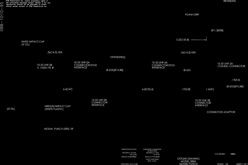
6 Installation and Operating Manual Model 088A ICP Modal Punch Manual Number Manual Revision: NR Contents: 1.0 Introduction Page Description.... Page Installation Page Operation Page Testing Page Calibration... Page Maintenance Page Cautions.. Page Customer Service Page INTRODUCTION The PCB Modal Punch is ideally suited for structural behavior testing. The Modal Punch allows the user to reach impact locations previously inaccessible by conventional impulse hammers. Impulse testing the dynamic behavior of mechanical structures involves positioning the Modal Punch at the desired measurement location on the structure, then striking the force-instrumented Modal Punch with a standard noninstrumented hammer and measuring the resultant motion with an accelerometer(s). Integration of the acceleration signal yields velocity or displacement data for use in computing classical transfer characteristics such as inertance, compliance, impedance, and mobility. Structures generally respond as (1) rigid or elastic bodies, (2) finite elements, lumped constant models, and (3) distributed parameter models conducting stress-strain (sound) waves. The impulse generated by the Modal Punch and the user s standard non-instrumented hammer consists of a nearly-constant force over a broad frequency range and is therefore capable of exciting all resonances in that range. The physical properties of the impact device, including size, weight, material, and velocity at impact determine the amplitude and frequency content (wave shape) of the force impulse. The impact cap material generally determines the frequency content. The mass of the Modal Punch and hammer, along with the velocity at impact, determine the energy content. 1
7 The type and size of the required impact device is determined by the test structure. The Model 088A Modal Punch was designed for use on intermediate size structures such as automotive axles, gearbox shafts, and machine tools. Large, heavy structures such as locomotive frames, tanks, and bridges require an instrumented sledge hammer (PCB model numbers 086D20 or 086D50). Small structures such as compressor blades or some electrical circuit boards often require a miniature instrumented hammer (PCB model number 086D80). Some very large structures may require a special mechanical ram instrumented with a force-sensing impact head. The Modal Punch is instrumented with a precision, quartz, ICP (low impedance) voltage mode force sensor. The built-in conditioning electronics allow ease of use and test setup, while the naturally-polarized quartz sensing element offers long-term stability and repeatability. 2.0 Description The Modal Punch consists of an integral ICP (Integrated Circuit Piezoelectric), quartz force sensor mounted on the impact head. The sensing element and built-in, solid state micro-electronics inside the force sensor function to transfer impact force into a low impedance analog signal for display and analysis. The cable is connected on the side of the Modal Punch s Connector Adaptor model number 070A41 (supplied) just below the impact surface. An Extension Shaft model 084A80 is also supplied to adjust the Modal Punch to the desired length. Additional shafts may also be purchased. A foam grip is supplied to provide a comfortable and secure grip and may be replaced when needed. The striking end of the Modal Punch s head has a threaded hole to accept a variety of impact tips. The tip functions to transfer the force of the impact into the sensor and protects the sensor face from damage. Tips of different stiffness allow the user to vary the pulse width and frequency content of the force. All component parts (impact head, extender, and connector adaptor) are laser-welded and epoxied at the factory to ensure reliable operation in adverse environmental conditions. 3.0 Installation To assemble the Modal Punch, choose the number of extenders required to reach the desired impact location, screw the extender onto the force-instrumented impact head, and attach the connector adaptor to the extender or the force-instrumented impact head, if an extender is not being utilized. To ensure a proper mechanical coupling between the parts of the Modal Punch, each piece should be securely screwed together. Care should be used not to over-torque the parts, which will cause permanent damage to the interface and connectors. A firm, hand-tight torque is sufficient to ensure a proper coupling. If desired, a small amount of silicone grease (DC-4 or equivalent) may be applied between the interfacing parts for an improved coupling. 2
8 Accelerometers install and connect according to the procedures described in the specific sensor manual. Accelerometers utilized for impact testing include the 353 Series of single axis accelerometers, and the 356 Series of triaxial accelerometers. For additional information regarding sensors to meet your impact testing needs, feel free to contact the PCB Vibration Division customer service group by calling toll-free in the USA (or outside the USA by calling ). In general, sensors connect to the ICP power unit at the jack labeled XDCR. The jack labeled SCOPE is connected to the readout device, FFT analyzer, or computer. Please consult the ICP power unit operating guide for proper installation and operating procedures. 4.0 Operation Follow the below operation instructions: 1). Assemble the Modal Punch to the desired length using the supplied extension (if required) and connector adaptor. Please reference the above installation procedures. 2). Choose the impact tip which corresponds to your excitation requirements. In general: A. A stiffer tip is recommended for higher frequency response. B. A softer tip is recommended for improved low frequency response. 3). Connect the Modal Punch to an ICP power supply or equivalent with a coaxial cable (not supplied). The Modal Punch requires a microdot connector plug. 4). Connect the corresponding output cable (not supplied) from your ICP power supply to your readout device. This step is not necessary if ICP power is built into your readout device. Tighten the cable connectors securely by hand to ensure good electrical contact. 5). Install accelerometer(s) in the desired measurement location(s), referring to the appropriate operating guides for the accelerometer(s) and power supplies being used. 6). Switch power on and wait a minute for the sensor amplifier to turn on and the coupling capacitor to fully charge. 7). Check the ICP power unit meter for normal operation. Normal operation is indicated when the meter pointer is pointing in the green area. If the meter reads in the red area, look for a shorted cable or connection. If the meter pointer is pointing in the yellow area, look for open cables or connections. 8). When all power unit meters indicate normal operation (meter pointer is pointing in the green area), proceed with tests, following all sensor, power unit, and analyzer operating instructions. 3
9 PCB s ICP constant-current power supply units provide the necessary excitation power for proper operation of the Modal Punch. These units provide the correct power and have circuit fault indicating meters and a bias decoupling capability to remove MOSFET turn on bias voltage from the measurement signal. Power units are available in a variety of configurations, including battery or AC versions and with additional signal conditioning features such as gain, filtering, and integration. Some FFT analyzers incorporate the proper excitation power for direct connection to ICP sensors. Be certain to confirm that the excitation from the power supply conforms to the requirements for the specific sensors being used. The Modal Punch requires 2 to 20 ma constant current and 24 to 27 VDC. CAUTION: The Modal Punch was designed to operate only with ICP power supply units. Do not attempt to troubleshoot the Modal Punch by connecting it to any device, such as an ohmmeter, which may introduce unregulated voltage, as damage to the precision internal micro-electronics may occur. If there is any doubt about the compatibility of a power supply unit or whether a power supply unit is required, feel free to contact the PCB Vibration Division customer service group by calling toll-free in the USA (or outside the USA by calling ). 5.0 Testing To test the behavior of your structure and to tailor the frequency bandwidth of the impact force, follow the below operation instructions: 1). Position the Modal Punch on the test structure at the desired location. Strike the punch with a standard non-instrumented hammer and process the results. Always take several averages to reduce the effects of spurious noises. CAUTION: Never impact without a tip properly installed on the Modal Punch, as permanent damage of the sensing element is likely to occur. Also, care should be exercised when striking the punch to ensure that the impact hammer does not slip and strike the operator s hand, causing personal injury. 2). Check the measured results for signal quality (adequate signal-to-noise) and no overloads (overloads lights or sharp flattening of time history peaks). 3). Analyze the results for frequency content and check to ensure that the reasonably flat portion of the force spectrum is sufficient to cover the structural resonances of interest present in the acceleration spectrum. Often, signal energy is sufficient to excite structural resonances at 20 db below initial low frequency force levels. 4). Change Modal Punch tips to modify dynamic behavior, if necessary. The following are general guidelines; the specific test structure plays an integral part in the selection: A. To obtain higher frequency response, use a stiffer, harder tip and a smaller hammer mass. B. To obtain improved low frequency response, use a softer hammer tip and larger hammer mass. 4
10 C. To increase signal energy of impact, increase the impact velocity and/or hammer mass. 5). Repeat steps 1 through 4 until satisfactory results are obtained. Generally speaking, the impact tips affect the impulse frequency content, while the mass of the impact device and velocity of impact affect the signal energy level. Frequency content and energy level are interrelated. Therefore, both will be affected by different hammer structures and Modal Punch configurations. Hammer velocity at impact will also affect both. In general, massive structures with lower stiffness require the use of a soft impact tip and large mass to adequately excite low frequency resonances. During testing, occasionally check and tighten the electrical and mechanical connections. Repeated impacting may loosen connections, which may result in erratic, noisy signals. Multiple impacts or penetration into the structure may occur when using too heavy a mass on too light a structure. This will appear as a series of peaks of decreasing amplitude in the time history data. Reject such data. Careful techniques used in the impact process can avoid this problem. In particular, if the Modal Punch is held against the test structure and allowed to freely recoil after impact, the double impact phenomena will be reduced or eliminated. Some skill and practice may be required to perfect this technique. Distortion, undershoot, and oscillation of the analyzer display is caused by ringing of the analyzer s anti-aliasing filters. This behavior is normal. To view the correct impulse waveform, switch the analyzer to a higher frequency range. 6.0 Calibration Calibration involves testing the functional transfer behavior (sensitivity) of the sensor under controlled laboratory conditions. Sensitivities to various inputs such as force, temperature, current, and frequency can be derived by relating the corresponding output to changes in these inputs. For impact hammers and the Modal Punch, the most important of these relationships is the sensitivity to the force input. The desired behavior is linear, since ideal sensors treat output and input amplitudes proportionally. In addition, the nominal sensitivity should be constant (linear frequency response) within the specific frequency range, and there should be no induced phase shift in the response (no delay in the signal). Different Modal Punch and hammer combinations have different sensitivities because the structure experiences a force greater than the crystal-sensing elements. The force of impact on the test structure is a function of the total mass of the Modal Punch and hammer, while the force on the crystals is a function of the mass behind them. The impact tip is located in front of the crystal. The differences in mass depend on the ratio of the tip mass to the mass behind the crystal. This is automatically compensated for when the Modal Punch is properly calibrated. 5
11 The Modal Punch can be calibrated by hitting a freely-suspended mass instrumented with a quartz reference accelerometer. The mass, pendulously suspended or placed on a piece of foam rubber, will behave as a rigid body. According to Newton s second law of motion, at any instant in time, the force experienced by the mass is simply the mass multiplied by the measured acceleration. On a storage oscilloscope, dividing the peak output signal of the hammer (mv) by the mass (lb) times the peak acceleration (g s) gives the hammer sensitivity directly in mv/lb. Calibration on a FFT analyzer produces the same result as a function of frequency. The transfer function of acceleration versus force produces a calibration constant (ideally 1/M) at each discrete frequency. This calibration curve is linear over a specified frequency range. PCB s Model 963A Gravimetric Calibrator is ideally suited for calibration of the Modal Punch. The device calibrates accelerometers, force sensors, and PCB Impulse Force Test Hammers and tests the functional transfer behavior, sensitivity, and phase of sensor structures. 7.0 Maintenance The rigid construction of the Modal Punch is designed to provide reliable, long-term service life. Problems may arise when the instrument is exposed to temperatures exceeding the specific range, prolonged exposure to moisture, or extremely high mechanical shock. There are no user-serviceable components in the Modal Punch, so users should not attempt to make repairs to the unit (and doing so will void the unit s warranty). Should service be required, the Modal Punch should be returned to the factory, along with a description of the problem, in order to expedite the repair process. Before sending the Modal Punch back to the factory for service, PCB recommends that all cables and connections be checked to verify that they are not the cause of the problem. 8.0 Cautions Although the Modal Punch is rugged in construction, personal injury or damage to the unit may result from misuse. When observed, the following precautions can ensure long service life and safe, accurate data acquisition: 1). Do not attempt to dismantle the sensor element from the Modal Punch structure. All service should be performed at the factory. 2). Never generate more than five times the rated impact force range for the Modal Punch. In general, observe the maximum force rating for a 10V output. 100 volts will destroy the precision built-in micro-electronics and/or the sensing element. 6
12 3). Never strike an object without an impact tip properly installed in front of the forcesensing element. Damaging the precision-lapped surface of the Modal Punch s sensor can affect its behavior. 4). During testing, periodically check and tighten tip, extensions, impact cap, and cable connections. Continuous impacting and vibration tends to loosen these interfaces, resulting in faulty operation. Machined flats on the tips facilitate tightening and removal. 5). Do not apply voltage to the unit without constant current protection. 6). Do not apply more than 20 ma s of current. 7). Do not exceed 30 volts supply voltage. 8). Do not subject the unit to temperatures above 250 F (121 C). 9). Exercise extreme caution when impacting the Modal Punch with a hammer. Missing the impact cap may lead to personal injury to the user. 9.0 CUSTOMER SERVICE PCB Piezotronics guarantees Total Customer Satisfaction. If, at any time, for any reason, you are not completely satisfied with any PCB product, PCB will repair, replace, or exchange it at no charge. You may also choose, within the warranty period, to have your purchase price refunded. Contact PCB Vibration Division Customer Service personnel by calling toll-free in the USA at or outside the USA at , or send an to vibration@pcb.com PCB offers to all customers, at no charge, 24-hour phone support. This service makes product or application support available to our customers, day or night, seven days a week. When unforeseen problems or emergency situations arise, call the PCB 24-Hour Sensorline at (716) , and an application specialist will assist you Walden Avenue, Depew, New York USA USA Toll Free Phone: International Phone: Fax: vibration@pcb.com Website: 7
13 Model Number MODAL PUNCH 088A Performance ENGLISH SI Sensitivity(± 15 %) 10 mv/lbf 2.25 mv/n Measurement Range ± 500 lbf pk ± 2224 N pk Frequency Range(-10 db)(hard Tip) 8 khz 8 khz [1][2] Frequency Range(-10 db)(medium Tip) 2.5 khz 2.5 khz [1][2] Resonant Frequency 10 khz 10 khz Non-Linearity 1 % 1 % Electrical Excitation Voltage 20 to 30 VDC 20 to 30 VDC Constant Current Excitation 2 to 20 ma 2 to 20 ma Output Impedance 100 Ohm 100 Ohm [1] Output Bias Voltage 8 to 12 VDC 8 to 12 VDC Discharge Time Constant 2000 sec 2000 sec [1] Physical Sensing Element Quartz Quartz Sealing Epoxy Epoxy Hammer Mass 3.5 oz 100 gm [1] Head Diameter in 15.9 mm Tip Diameter 0.25 in 6.4 mm Size (Height) 6.6 in mm Extender Mass Weight 2.8 oz 80 gm [1] Electrical Connector Coaxial Jack Coaxial Jack Revision: C ECN #: OPTIONAL VERSIONS Optional versions have identical specifications and accessories as listed for the standard model except where noted below. More than one option may be used. NOTES: [1] Typical. [2] Varies depending on test structure. These values are from hitting a stiff steel mass. Hammer did not have extender mass attached. [3] See PCB Declaration of Conformance PS068 for details. SUPPLIED ACCESSORIES: Model 070A41 Modal punch connector adapter, connector (1) Model 084A20 Special steel tip, 2" x 1/8" dia. (for Modal punch only) (1) Model 084A80 Modal punch extender, 6" (1) Model 084B03 Hard Tip- Hard (S.S) (1) Model 084B04 Hammer Tip- Medium (White Plastic) (1) Model 085A10 Vinyl Cover For Medium Tip (Blue) (1) Model 085A25 Foam Grip (1) Model HCS-2 Calibration of Series 086 instrumented impact hammers (1) [3] All specifications are at room temperature unless otherwise specified. In the interest of constant product improvement, we reserve the right to change specifications without notice. ICP is a registered trademark of PCB Group, Inc. Entered: LK Engineer: SDS Sales: WDC Approved: JJB Spec Number: Date: 3/16/2018 Date: 3/16/2018 Date: 3/16/2018 Date: 3/16/ Walden Avenue, Depew, NY Phone: Fax: info@pcb.com
14
Model 621B40. Very High Frequency ICP Accelerometer. Installation and Operating Manual
 Model 621B40 Very High Frequency ICP Accelerometer Installation and Operating Manual For assistance with the operation of this product, contact PCB Piezotronics, Inc. Toll-free: 800-959-4464 24-hour SensorLine:
Model 352A25. Miniature, lightweight (0.6 gm) ceramic shear ICP accel., 2.5 mv/g, 1 to. Installation and Operating Manual
 ceramic shear ICP accel., 2.5 mv/g, 1 to. Installation and Operating Manual") Model 352A25 Miniature, lightweight (0.6 gm) ceramic shear ICP accel., 2.5 mv/g, 1 to Installation and Operating Manual For assistance with the operation of this product, contact PCB Piezotronics, Inc.
Model 352A25 Miniature, lightweight (0.6 gm) ceramic shear ICP accel., 2.5 mv/g, 1 to Installation and Operating Manual For assistance with the operation of this product, contact PCB Piezotronics, Inc.
Model TLD356M155 TRIAXIAL ICP ACCELEROMETER. Installation and Operating Manual
 Model TLD356M155 TRIAXIAL ICP ACCELEROMETER Installation and Operating Manual For assistance with the operation of this product, contact PCB Piezotronics, Inc. Toll-free: 800-828-8840 24-hour SensorLine:
Model 333B52. Modal array, ceramic shear ICP accel, 1000 mv/g, 0.5 to 3k Hz, side. Installation and Operating Manual
 Model 333B52 Modal array, ceramic shear ICP accel, 1000 mv/g, 0.5 to 3k Hz, 10-32 side Installation and Operating Manual For assistance with the operation of this product, contact PCB Piezotronics, Inc.
Model 608A10. Industrial ICP Accelerometer. Installation and Operating Manual
 Model 608A10 Industrial ICP Accelerometer Installation and Operating Manual For assistance with the operation of this product, contact PCB Piezotronics, Inc. Toll-free: 800-959-4464 24-hour SensorLine:
Model 134A24 Tourmaline ICP pressure bar, 1000 psi, 5 mv/psi, 0.2 microsecond rise. Installation and Operating Manual
 Model 134A24 Tourmaline ICP pressure bar, 1000 psi, 5 mv/psi, 0.2 microsecond rise Installation and Operating Manual This manual contains the 402A installation and operating manuals that comprise a Model
Model TLD352A57. ICP Accelerometer. Installation and Operating Manual
 Model TLD352A57 ICP Accelerometer Installation and Operating Manual For assistance with the operation of this product, contact PCB Piezotronics, Inc. Toll-free: 800-828-8840 24-hour SensorLine: 716-684-0001
Model 350C04. ICP Shock Accelerometer. Installation and Operating Manual
 Model 350C04 ICP Shock Accelerometer Installation and Operating Manual For assistance with the operation of this product, contact PCB Piezotronics, Inc. Toll-free: 800-828-8840 24-hour SensorLine: 716-684-0001
Model 480B21. 3-channel, Battery-powered, ICP Sensor Signal Conditioner. Installation and Operating Manual
 Model 480B21 3-channel, Battery-powered, ICP Sensor Signal Conditioner Installation and Operating Manual For assistance with the operation of this product, contact PCB Piezotronics, Inc. Toll-free: 800-828-8840
Model 350A43. Triaxial ICP Shock Accelerometer. Installation and Operating Manual
 Model 350A43 Triaxial ICP Shock Accelerometer Installation and Operating Manual For assistance with the operation of this product, contact the PCB Piezotronics, Inc. Toll-free: 716-684-0001 24-hour SensorLine:
Model 480E09. 1-Channel, battery-powered, ICP sensor signal conditioner, gain x1, x10, Installation and Operating Manual
 Model 480E09 1-Channel, battery-powered, ICP sensor signal conditioner, gain x1, x10, Installation and Operating Manual For assistance with the operation of this product, contact PCB Piezotronics, Inc.
Model HT356B01. Triaxial ICP Accelerometer. Installation and Operating Manual
 Model HT356B01 Triaxial ICP Accelerometer Installation and Operating Manual For assistance with the operation of this product, contact the PCB Piezotronics, Inc. Toll-free: 716-684-0001 24-hour SensorLine:
Model 640B ma Output Velocity Sensor. Installation and Operating Manual
 Model 640B71 4-20 ma Output Velocity Sensor Installation and Operating Manual For assistance with the operation of this product, contact PCB Piezotronics, Inc. Toll-free: 800-959-4464 24-hour SensorLine:
Model 356A13. Triaxial ICP Accelerometer. Installation and Operating Manual
 Model 356A13 Triaxial ICP Accelerometer Installation and Operating Manual For assistance with the operation of this product, contact PCB Piezotronics, Inc. Toll-free: 800-828-8840 24-hour SensorLine: 716-684-0001
Model 691A51/02. Platinum BNC Termination Box. Installation and Operating Manual
 Model 691A51/02 Platinum BNC Termination Box Installation and Operating Manual For assistance with the operation of this product, contact PCB Piezotronics, Inc. Toll-free: 800-959-4464 24-hour SensorLine:
Model 103B12 PRESSURE SENSOR, ICP, ACOUSTIC. Installation and Operating Manual
 Model 103B12 PRESSURE SENSOR, ICP, ACOUSTIC Installation and Operating Manual For assistance with the operation of this product, contact PCB Piezotronics, Inc. Toll-free: 800-828-8840 24-hour SensorLine:
Model 105C12. ICP Pressure Sensor. Installation and Operating Manual
 Model 105C12 ICP Pressure Sensor Installation and Operating Manual For assistance with the operation of this product, contact PCB Piezotronics, Inc. Toll-free: 800-828-8840 24-hour SensorLine: 716-684-0001
Model EX600B13. Very High Temperature Industrial ICP Accelerometer. Installation and Operating Manual
 Model EX600B13 Very High Temperature Industrial ICP Accelerometer Installation and Operating Manual For assistance with the operation of this product, contact PCB Piezotronics, Inc. Toll-free: 800-959-4464
Model 699A ma Loop Calibrator. Installation and Operating Manual
 Model 699A05 4-20 ma Loop Calibrator Installation and Operating Manual For assistance with the operation of this product, contact PCB Piezotronics, Inc. Toll-free: 800-959-4464 24-hour SensorLine: 716-684-0001
Model 478B05. 3 Channel DC Sensor Signal Conditioner. Installation and Operating Manual
 Model 478B05 3 Channel DC Sensor Signal Conditioner Installation and Operating Manual For assistance with the operation of this product, contact PCB Piezotronics, Inc. Toll-free: 800-828-8840 24-hour SensorLine:
Model 352C23. Platinum Stock Products; Miniature, lightweight (0.2 gm), ceramic shear. Installation and Operating Manual
, ceramic shear. Installation and Operating Manual") Model 352C23 Platinum Stock Products; Miniature, lightweight (0.2 gm), ceramic shear Installation and Operating Manual For assistance with the operation of this product, contact PCB Piezotronics, Inc.
Model 352C23 Platinum Stock Products; Miniature, lightweight (0.2 gm), ceramic shear Installation and Operating Manual For assistance with the operation of this product, contact PCB Piezotronics, Inc.
Model 356B41. Triax ICP Seat Pad Accelerometer per ISO Installation and Operating Manual
 Model 356B41 Triax ICP Seat Pad Accelerometer per ISO 10326-1 Installation and Operating Manual For assistance with the operation of this product, contact PCB Piezotronics, Inc. Toll-free: 800-828-8840
Model A. DIN Rail Strain Gage Conditioner. Installation and Operating Manual
 Model 8161-011A DIN Rail Strain Gage Conditioner Installation and Operating Manual For assistance with the operation of this product, contact PCB Piezotronics, Inc. Toll-free: 800-828-8840 24-hour SensorLine:
Model 422E55. In-Line Charge Amplifier. Installation and Operating Manual
 Model 422E55 In-Line Charge Amplifier Installation and Operating Manual For assistance with the operation of this product, contact PCB Piezotronics, Inc. Toll-free: 800-828-8840 24-hour SensorLine: 716-684-0001
Model 356A33. Platinum Stock Products; Triaxial, ceramic shear ICP accel., 10 mv/g, 2 to. Installation and Operating Manual
 Model 356A33 Platinum Stock Products; Triaxial, ceramic shear ICP accel., 10 mv/g, 2 to Installation and Operating Manual For assistance with the operation of this product, contact PCB Piezotronics, Inc.
Model J351B41. Cryogenic, quartz shear ICP accel., 100 mv/g, 1 to 2k Hz, side conn. Installation and Operating Manual
 Model J351B41 Cryogenic, quartz shear ICP accel., 100 mv/g, 1 to 2k Hz, 10-32 side conn. Installation and Operating Manual For assistance with the operation of this product, contact PCB Piezotronics, Inc.
Model 687A01. Handheld Vibration Meter Kit. Installation and Operating Manual
 Model 687A01 Handheld Vibration Meter Kit Installation and Operating Manual This manual contains the 080A131, 603C01, 687A02 installation and operating manuals that comprise a Model 687A01 Handheld Vibration
Model 339A31. Triaxial ICP Accelerometer. Installation and Operating Manual
 Model 339A31 Triaxial ICP Accelerometer Installation and Operating Manual For assistance with the operation of this product, contact PCB Piezotronics, Inc. Toll-free: 800-828-8840 24-hour SensorLine: 716-684-0001
Model 682A09 IN-LINE ICP TO 4-20 MA OUTPUT VELOCITY CONVERTER. Installation and Operating Manual
 Model 682A09 IN-LINE ICP TO 4-20 MA OUTPUT VELOCITY CONVERTER Installation and Operating Manual For assistance with the operation of this product, contact PCB Piezotronics, Inc. Toll-free: 800-959-4464
Model 3711D1FA3G. DC Accelerometer. Installation and Operating Manual
 Model 3711D1FA3G DC Accelerometer Installation and Operating Manual For assistance with the operation of this product, contact PCB Piezotronics, Inc. Toll-free: 800-828-8840 24-hour SensorLine: 716-684-0001
Model 356B20. Triaxial, miniature (4 gm), ceramic shear ICP accel., 1 mv/g, 2 to 7k Hz, Installation and Operating Manual
, ceramic shear ICP accel., 1 mv/g, 2 to 7k Hz, Installation and Operating Manual") Model 356B20 Triaxial, miniature (4 gm), ceramic shear ICP accel., 1 mv/g, 2 to 7k Hz, Installation and Operating Manual For assistance with the operation of this product, contact PCB Piezotronics, Inc.
Model 356B20 Triaxial, miniature (4 gm), ceramic shear ICP accel., 1 mv/g, 2 to 7k Hz, Installation and Operating Manual For assistance with the operation of this product, contact PCB Piezotronics, Inc.
Model 102B18. ICP Pressure Sensor. Installation and Operating Manual
 Model 102B18 ICP Pressure Sensor Installation and Operating Manual For assistance with the operation of this product, contact PCB Piezotronics, Inc. Toll-free: 800-828-8840 24-hour SensorLine: 716-684-0001
Model 333B50. Platinum Stock Products; Modal array, ceramic shear ICP accel, Installation and Operating Manual
 Model 333B50 Platinum Stock Products; Modal array, ceramic shear ICP accel, 1000 Installation and Operating Manual For assistance with the operation of this product, contact PCB Piezotronics, Inc. Toll-free:
Model A. Strain Gage Sensor Signal Condition. Installation and Operating Manual
 Model 8162-011A Strain Gage Sensor Signal Condition Installation and Operating Manual For assistance with the operation of this product, contact PCB Piezotronics, Inc. Toll-free: 800-828-8840 24-hour SensorLine:
Model 356A16. Triaxial ICP Accelerometer. Installation and Operating Manual
 Model 356A16 Triaxial ICP Accelerometer Installation and Operating Manual For assistance with the operation of this product, contact the PCB Piezotronics, Inc. Toll-free: 716-684-0001 24-hour SensorLine:
Model M320C15. ESS mini (2 gm), quartz shear ICP accel., 10 mv/g, 2 to 10k Hz, 5-44 side. Installation and Operating Manual
, quartz shear ICP accel., 10 mv/g, 2 to 10k Hz, 5-44 side. Installation and Operating Manual") Model M320C15 ESS mini (2 gm), quartz shear ICP accel., 10 mv/g, 2 to 10k Hz, 5-44 side Installation and Operating Manual For assistance with the operation of this product, contact PCB Piezotronics, Inc.
Model M320C15 ESS mini (2 gm), quartz shear ICP accel., 10 mv/g, 2 to 10k Hz, 5-44 side Installation and Operating Manual For assistance with the operation of this product, contact PCB Piezotronics, Inc.
Model J356A43. Triaxial ICP Accelerometer. Installation and Operating Manual
 Model J356A43 Triaxial ICP Accelerometer Installation and Operating Manual For assistance with the operation of this product, contact the PCB Piezotronics, Inc. Toll-free: 76-684-000 4-hour SensorLine:
Model 482A21. 1-channel, line-powered, ICP sensor signal cond., unity gain, BNC. Installation and Operating Manual
 Model 482A21 1-channel, line-powered, ICP sensor signal cond., unity gain, BNC Installation and Operating Manual For assistance with the operation of this product, contact PCB Piezotronics, Inc. Toll-free:
Model 379A02. Microphone Array Stand. Installation and Operating Manual
 Model 379A02 Microphone Array Stand Installation and Operating Manual For assistance with the operation of this product, contact PCB Piezotronics, Inc. Toll-free: 800-828-8840 24-hour SensorLine: 716-684-0001
Model 353B17. High frequency, quartz shear ICP accel., 10 mv/g, 1 to 10k Hz, 10-ft. Installation and Operating Manual
 Model 353B17 High frequency, quartz shear ICP accel., 10 mv/g, 1 to 10k Hz, 10-ft Installation and Operating Manual For assistance with the operation of this product, contact PCB Piezotronics, Inc. Toll-free:
Model TLD352M131. High sensitivity, ceramic shear ICP accel., 100 mv/g, 0.2 Hz to 20k Hz (+/- 2 db), top conn., mtg stud, ground isolated
, top conn., mtg stud, ground isolated") Model TLD352M131 High sensitivity, ceramic shear ICP accel., 100 mv/g, 0.2 Hz to 20k Hz (+/- 2 db), 10-32 top conn., 10-32 mtg stud, ground isolated Installation and Operating Manual For assistance with
Model TLD352M131 High sensitivity, ceramic shear ICP accel., 100 mv/g, 0.2 Hz to 20k Hz (+/- 2 db), 10-32 top conn., 10-32 mtg stud, ground isolated Installation and Operating Manual For assistance with
Model 684A03. Triple Channel BNC Output Enclosure. Installation and Operating Manual
 Model 684A03 Triple Channel BNC Output Enclosure Installation and Operating Manual For assistance with the operation of this product, contact PCB Piezotronics, Inc. Toll-free: 800-959-4464 24-hour SensorLine:
Model 422E36. In-Line Charge Converter. Installation and Operating Manual
 Model 422E36 In-Line Charge Converter Installation and Operating Manual For assistance with the operation of this product, contact PCB Piezotronics, Inc. Toll-free: 800-828-8840 24-hour SensorLine: 716-684-0001
Model TLD339A36. Triaxial ICP Accelerometer. Installation and Operating Manual
 Model TLD339A36 Triaxial ICP Accelerometer Installation and Operating Manual For assistance with the operation of this product, contact the PCB Piezotronics, Inc. Toll-free: 716-684-0001 24-hour SensorLine:
Model 132A31. Micro ICP pressure sensor, 140 mv/psi, pigtail conn. (for high frequency. Installation and Operating Manual
 Model 132A31 Micro ICP pressure sensor, 140 mv/psi, pigtail conn. (for high frequency Installation and Operating Manual For assistance with the operation of this product, contact PCB Piezotronics, Inc.
Model 113B21/062A01. ICP Pressure Sensor. Installation and Operating Manual
 Model 113B21/062A01 ICP Pressure Sensor Installation and Operating Manual For assistance with the operation of this product, contact PCB Piezotronics, Inc. Toll-free: 800-828-8840 24-hour SensorLine: 716-684-0001
Model 682C05 BEARING FAULT DETECTOR. Installation and Operating Manual
 Model 682C05 BEARING FAULT DETECTOR Installation and Operating Manual For assistance with the operation of this product, contact the PCB Piezotronics, Inc. Toll-free: 800-959-4464 24-hour SensorLine: 716-684-0001
Model TLD356A02. Platinum Stock Products; Triaxial, general purpose, ceramic shear ICP. Installation and Operating Manual
 Model TLD356A02 Platinum Stock Products; Triaxial, general purpose, ceramic shear ICP Installation and Operating Manual For assistance with the operation of this product, contact PCB Piezotronics, Inc.
Model 130B40 ICP ELECTRET SURFACE MICROPHONE. Installation and Operating Manual
 Model 130B40 ICP ELECTRET SURFACE MICROPHONE Installation and Operating Manual For assistance with the operation of this product, contact PCB Piezotronics, Inc. Toll-free: 800-828-8840 24-hour SensorLine:
Model 288D01. Mechanical Impedance Sensor. Installation and Operating Manual
 Model 288D01 Mechanical Impedance Sensor Installation and Operating Manual For assistance with the operation of this product, contact PCB Piezotronics, Inc. Toll-free: 800-828-8840 24-hour SensorLine:
Model TLD288D01. Mechanical Impedance Sensor. Installation and Operating Manual
 Model TLD288D01 Mechanical Impedance Sensor Installation and Operating Manual For assistance with the operation of this product, contact PCB Piezotronics, Inc. Toll-free: 800-828-8840 24-hour SensorLine:
Model 377B26 PROBE MICROPHONE ICP. Installation and Operating Manual
 Model 377B26 PROBE MICROPHONE ICP Installation and Operating Manual For assistance with the operation of this product, contact PCB Piezotronics, Inc. Toll-free: 800-828-8840 24-hour SensorLine: 716-684-0001
Model 482C05. Four-channel, ICP Sensor Signal Conditioner. Installation and Operating Manual
 Model 482C05 Four-channel, ICP Sensor Signal Conditioner Installation and Operating Manual For assistance with the operation of this product, contact PCB Piezotronics, Inc. Toll-free: 800-828-8840 24-hour
Model 356B40. Sell 356B41. Installation and Operating Manual
 Model 356B40 Sell 356B41 Installation and Operating Manual For assistance with the operation of this product, contact PCB Piezotronics, Inc. Toll-free: 800-828-8840 24-hour SensorLine: 716-684-0001 Fax:
Model RHM240A03. Uniaxial ICP Strain Sensor. Installation and Operating Manual
 Model RHM240A03 Uniaxial ICP Strain Sensor Installation and Operating Manual For assistance with the operation of this product, contact PCB Piezotronics, Inc. Toll-free: 800-828-8840 24-hour SensorLine:
Model C STRAIN GAGE LOAD CELL. Installation and Operating Manual
 Model 1631-06C STRAIN GAGE LOAD CELL Installation and Operating Manual For assistance with the operation of this product,contact: PCB Load & Torque, Inc. Toll-free: 866-684-7107 24-hour SensorLine : 716-684-0001
Model 3501A1260KG HIGH AMPLITUDE MEMS SHOCK ACCELEROMETER. Installation and Operating Manual
 Model 3501A1260KG HIGH AMPLITUDE MEMS SHOCK ACCELEROMETER Installation and Operating Manual For assistance with the operation of this product, contact PCB Piezotronics, Inc. Toll-free: 800-828-8840 24-hour
Model 629A31. Precision Triaxial Industrial ICP Accelerometer. Installation and Operating Manual
 Model 629A31 Precision Triaxial Industrial ICP Accelerometer Installation and Operating Manual For assistance with the operation of this product, contact PCB Piezotronics, Inc. Toll-free: 800-959-4464
Model 626B01. Low Frequency Industrial ICP Accelerometer. Installation and Operating Manual
 Model 626B01 Low Frequency Industrial ICP Accelerometer Installation and Operating Manual For assistance with the operation of this product, contact PCB Piezotronics, Inc. Toll-free: 800-959-4464 24-hour
Model 600A13. Very High Temperature ICP Accelerometer Kit. Installation and Operating Manual
 Model 600A13 Very High Temperature ICP Accelerometer Kit Installation and Operating Manual For assistance with the operation of this product, contact PCB Piezotronics, Inc. Toll-free: 800-959-4464 24-hour
Model 130F21. ICP Electret Array Microphone. Installation and Operating Manual
 Model 130F21 ICP Electret Array Microphone Installation and Operating Manual For assistance with the operation of this product, contact PCB Piezotronics, Inc. Toll-free: 800-828-8840 24-hour SensorLine:
Model 685A09. Mechanical Vibration Switch. Installation and Operating Manual
 Model 685A09 Mechanical Vibration Switch Installation and Operating Manual For assistance with the operation of this product, contact PCB Piezotronics, Inc. Toll-free: 800-959-4464 24-hour SensorLine:
Model 421A31 DIFFERENTIAL INPUT IN LINE CHARGE AMPLIFIER. Installation and Operating Manual
 Model 421A31 DIFFERENTIAL INPUT IN LINE CHARGE AMPLIFIER Installation and Operating Manual For assistance with the operation of this product, contact PCB Piezotronics, Inc. Toll-free: 800-828-8840 24-hour
Model 340A50. Triaxial, miniature (11 gm) charge output accel., 2.7 pc/g, (3) M3 conn. Installation and Operating Manual
 charge output accel., 2.7 pc/g, (3) M3 conn. Installation and Operating Manual") Model 340A50 Triaxial, miniature (11 gm) charge output accel., 2.7 pc/g, (3) M3 conn. Installation and Operating Manual For assistance with the operation of this product, contact PCB Piezotronics, Inc.
Model 340A50 Triaxial, miniature (11 gm) charge output accel., 2.7 pc/g, (3) M3 conn. Installation and Operating Manual For assistance with the operation of this product, contact PCB Piezotronics, Inc.
Model 3503C2060KG. Surface Mount Piezoresistive Triaxial Shock Accelerometer. Installation and Operating Manual
 Model 3503C2060KG Surface Mount Piezoresistive Triaxial Shock Accelerometer Installation and Operating Manual For assistance with the operation of this product, contact PCB Piezotronics, Inc. Toll-free:
Model 3503C202KG. Surface Mount Piezoresistive Triaxial Shock Accelerometer. Installation and Operating Manual
 Model 3503C202KG Surface Mount Piezoresistive Triaxial Shock Accelerometer Installation and Operating Manual For assistance with the operation of this product, contact PCB Piezotronics, Inc. Toll-free:
Model 421A30. DIFFERENTIAL INPUT IN-LINE Charge Amplifier. Installation and Operating Manual
 Model 421A30 DIFFERENTIAL INPUT IN-LINE Charge Amplifier Installation and Operating Manual For assistance with the operation of this product, contact PCB Piezotronics, Inc. Toll-free: 800-828-8840 24-hour
Model 3503C2060KG. Surface Mount Piezoresistive Triaxial Shock Accelerometer. Installation and Operating Manual
 Model 3503C2060KG Surface Mount Piezoresistive Triaxial Shock Accelerometer Installation and Operating Manual For assistance with the operation of this product, contact PCB Piezotronics, Inc. Toll-free:
Model HT378B02. ICP Microphone System. Installation and Operating Manual
 Model HT378B02 ICP Microphone System Installation and Operating Manual For assistance with the operation of this product, contact the PCB Piezotronics, Inc. Toll-free: 716-684-0001 24-hour SensorLine:
Model 394C06. Handheld shaker, 1g at Hz (for up to 210 grams total weight of. Installation and Operating Manual
 Model 394C06 Handheld shaker, g at 59. Hz (for up to 0 grams total weight of Installation and Operating Manual For assistance with the operation of this product, contact PCB Piezotronics, Inc. Toll-free:
Model 642A ma Output Velocity Sensor. Installation and Operating Manual
 Model 642A01 4-20 ma Output Velocity Sensor Installation and Operating Manual For assistance with the operation of this product, contact PCB Piezotronics, Inc. Toll-free: 800-959-4464 24-hour SensorLine:
Model 640B ma Output Velocity Sensor. Installation and Operating Manual
 Model 640B02 4-20 ma Output Velocity Sensor Installation and Operating Manual For assistance with the operation of this product, contact PCB Piezotronics, Inc. Toll-free: 800-959-4464 24-hour SensorLine:
Model A. Strain Gage Load Cell. Installation and Operating Manual
 Model 1102-02A Strain Gage Load Cell Installation and Operating Manual For assistance with the operation of this product,contact: PCB Load & Torque, Inc. Toll-free: 866-684-7107 24-hour SensorLine : 716-684-0001
Model M A. rod end load cell. Installation and Operating Manual
 Model M1381-001-01A rod end load cell Installation and Operating Manual For assistance with the operation of this product, contact PCB Piezotronics, Inc. Toll-free: 800-828-8840 24-hour SensorLine: 716-684-0001
Model EX603C02. Low-cost Industrial ICP Accelerometer. Installation and Operating Manual
 Model EX603C02 Low-cost Industrial ICP Accelerometer Installation and Operating Manual For assistance with the operation of this product, contact PCB Piezotronics, Inc. Toll-free: 800-959-4464 24-hour
Model 357A05. Charge output accel., high temp., 17 pc/g, 500 g, 10kHz, side conn., Installation and Operating Manual
 Model 357A05 Charge output accel., high temp., 17 pc/g, 500 g, 10kHz, 10-32 side conn., Installation and Operating Manual For assistance with the operation of this product, contact PCB Piezotronics, Inc.
Model 378C20 ICP MICROPHONE SYSTEM. Installation and Operating Manual
 Model 378C20 ICP MICROPHONE SYSTEM Installation and Operating Manual This manual contains the 377C20, 426E01 installation and operating manuals that comprise a Model 378C20 ICP MICROPHONE SYSTEM kit. For
Model 378B02. ICP Microphone System. Installation and Operating Manual
 Model 378B02 ICP Microphone System Installation and Operating Manual This manual contains the 377B02, 426E01 installation and operating manuals that comprise a Model 378B02 ICP Microphone System kit. For
Model A. rod end load cell. Installation and Operating Manual
 Model 1381-04A rod end load cell Installation and Operating Manual For assistance with the operation of this product,contact: PCB Load & Torque, Inc. Toll-free: 866-684-7107 24-hour SensorLine : 716-684-0001
Model 200C20. ICP Force Sensor. Installation and Operating Manual
 Model 200C20 ICP Force Sensor Installation and Operating Manual For assistance with the operation of this product, contact PCB Piezotronics, Inc. Toll-free: 800-828-8840 24-hour SensorLine: 716-684-0001
Model 378B02. Installation and Operating Manual. For assistance with the operation of this product, contact the PCB Piezotronics, Inc.
 Model 378B02 1/2" prepolarized free-field condenser microphone, 50 mv/pa (+/-1.5 db), 3.15 Hz - 20 khz (+/-2 db) with 1/2" ICP preamplifier (426E01) and TEDS Installation and Operating Manual For assistance
Model 260A01. Triax ICP force sensor, 1k lb (Fz), 500 lb (Fx,y), 2.5 mv/lb (z), 10 mv/lb (x, Installation and Operating Manual
, 500 lb (Fx,y), 2.5 mv/lb (z), 10 mv/lb (x, Installation and Operating Manual") Model 260A01 Triax ICP force sensor, 1k lb (Fz), 500 lb (Fx,y), 2.5 mv/lb (z), 10 mv/lb (x, Installation and Operating Manual For assistance with the operation of this product, contact PCB Piezotronics,
Model 260A01 Triax ICP force sensor, 1k lb (Fz), 500 lb (Fx,y), 2.5 mv/lb (z), 10 mv/lb (x, Installation and Operating Manual For assistance with the operation of this product, contact PCB Piezotronics,
Model M260A01. Triax ICP force sensor, 1k lb (Fz), 500 lb (Fx,y), 2.5 mv/lb (z), 10 mv/lb (x, Installation and Operating Manual
, 500 lb (Fx,y), 2.5 mv/lb (z), 10 mv/lb (x, Installation and Operating Manual") Model M260A01 Triax ICP force sensor, 1k lb (Fz), 500 lb (Fx,y), 2.5 mv/lb (z), 10 mv/lb (x, Installation and Operating Manual For assistance with the operation of this product, contact PCB Piezotronics,
Model M260A01 Triax ICP force sensor, 1k lb (Fz), 500 lb (Fx,y), 2.5 mv/lb (z), 10 mv/lb (x, Installation and Operating Manual For assistance with the operation of this product, contact PCB Piezotronics,
Model 377B02/426A10. Precision Condenser Microphone. Installation and Operating Manual
 Model 377B02/426A10 Precision Condenser Microphone Installation and Operating Manual For assistance with the operation of this product, contact PCB Piezotronics, Inc. Toll-free: 800-828-8840 24-hour SensorLine:
Model 357C71. Charge Output Accelerometer. Installation and Operating Manual
 Model 357C7 Charge Output Accelerometer Installation and Operating Manual For assistance with the operation of this product, contact PCB Piezotronics, Inc. Toll-free: 800-88-8840 4-hour SensorLine: 76-684-000
Model A. Reaction Torque Sensor. Installation and Operating Manual
 Model 2304-01A Reaction Torque Sensor Installation and Operating Manual For assistance with the operation of this product,contact: PCB Load & Torque, Inc. Toll-free: 866-684-7107 24-hour SensorLine : 716-684-0001
Model 3713B11200G. Triaxial DC Response Accelerometer. Installation and Operating Manual
 Model 37300G Triaxial DC Response Accelerometer Installation and Operating Manual For assistance with the operation of this product, contact PC Piezotronics, Inc. Toll-free: 800-88-8840 4-hour SensorLine:
Model 3713B1130G. Triaxial DC Response Accelerometer. Installation and Operating Manual
 Model 37330G Triaxial DC Response Accelerometer Installation and Operating Manual For assistance with the operation of this product, contact PC Piezotronics, Inc. Toll-free: 800-88-8840 4-hour SensorLine:
Model ROTARY TORQUE, W/ENCODER and AUTO ID. Installation and Operating Manual
 Model 039237-50022 ROTARY TORQUE, W/ENCODER and AUTO ID Installation and Operating Manual For assistance with the operation of this product, contact PCB Piezotronics, Inc. Toll-free: 800-828-8840 24-hour
Model EX646B71 ACCELEROMETER. Installation and Operating Manual
 Model EX646B71 ACCELEROMETER Installation and Operating Manual For assistance with the operation of this product, contact PCB Piezotronics, Inc. Toll-free: 800-959-4464 24-hour SensorLine: 716-684-0001
Model 116B. Charge Output Pressure Sensor. Installation and Operating Manual
 Model 116B Charge Output Pressure Sensor Installation and Operating Manual For assistance with the operation of this product, contact PCB Piezotronics, Inc. Toll-free: 800-828-8840 24-hour SensorLine:
Model HAND TORQUE WRENCH. Installation and Operating Manual
 Model 027137-04022 HAND TORQUE WRENCH Installation and Operating Manual For assistance with the operation of this product, contact PCB Piezotronics, Inc. Toll-free: 800-828-8840 24-hour SensorLine: 716-684-0001
Model A. DIN Rail Strain Gage Conditioner. Installation and Operating Manual
 Model 8161-011A DIN Rail Strain Gage Conditioner Installation and Operating Manual For assistance with the operation of this product, contact PCB Piezotronics, Inc. Toll-free: 800-828-8840 24-hour SensorLine:
Model 357B81. Charge Output Accelerometer. Installation and Operating Manual
 Model 357B8 Charge Output Accelerometer Installation and Operating Manual For assistance with the operation of this product, contact PCB Piezotronics, Inc. Toll-free: 800-88-8840 4-hour SensorLine: 76-684-000
Model Hand Torque Wrench. Installation and Operating Manual
 Model 027375-07501 Hand Torque Wrench Installation and Operating Manual For assistance with the operation of this product, contact PCB Piezotronics, Inc. Toll-free: 800-828-8840 24-hour SensorLine: 716-684-0001
Model 3713E1110G. Triaxial DC Response Accelerometer. Installation and Operating Manual
 Model 373E0G Triaxial DC Response Accelerometer Installation and Operating Manual For assistance with the operation of this product, contact PC Piezotronics, Inc. Toll-free: 800-88-8840 4-hour SensorLine:
AME 140X. ENGLISH Actuators for modulating control AME 140X Page 5. Operating Guide. Danfoss VI.IR.A2.02 1
 Operating Guide AME 40X AME 40X + VZ, VZ AME 40X + VZ 3, VZ 3 AME 40X + VZ 4, VZ 4 ENGISH Actuators for modulating control AME 40X www.danfoss.com Page 5 Danfoss 07.0 VI.IR.A.0 I AME 40X MAINTENANCE FREE
Model 5308D-01A. TORKDISC Rotary Torque Sensing System. Installation and Operating Manual
 Model 5308D-01A TORKDISC Rotary Torque Sensing System Installation and Operating Manual For assistance with the operation of this product,contact: PCB Load & Torque, Inc. Toll-free: 866-684-7107 24-hour
Model 8120F-410A. Strain Gage Sensor Signal Conditioner. Installation and Operating Manual
 Model 8120F-410A Strain Gage Sensor Signal Conditioner Installation and Operating Manual For assistance with the operation of this product, contact PCB Piezotronics, Inc. Toll-free: 800-828-8840 24-hour
Model 3713D1FE200G. Triaxial DC Accelerometer. Installation and Operating Manual
 Model 3713D1FE200G Triaxial DC Accelerometer Installation and Operating Manual For assistance with the operation of this product, contact PCB Piezotronics, Inc. Toll-free: 800-828-8840 24-hour SensorLine: