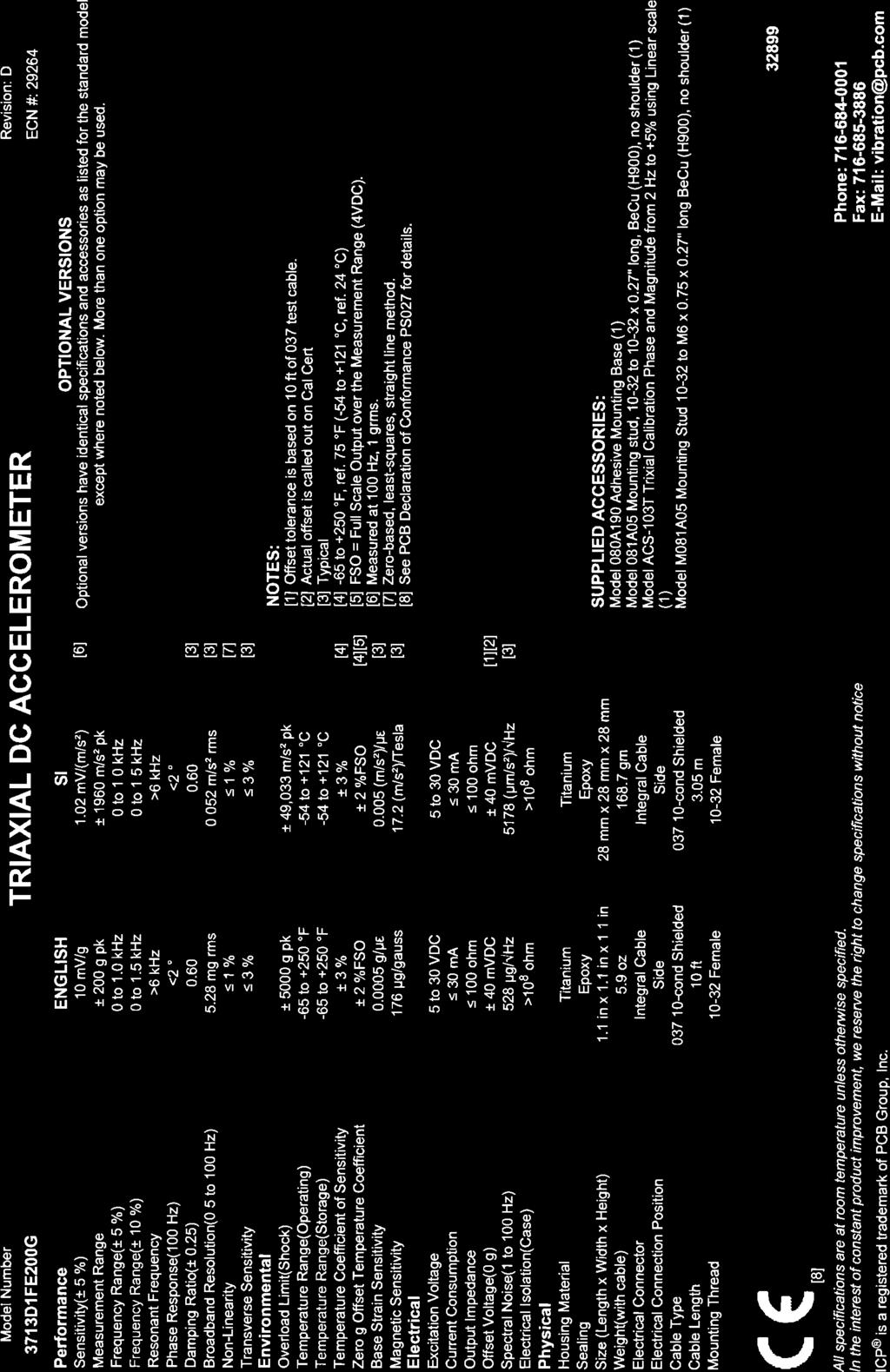
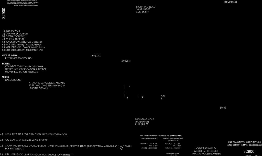
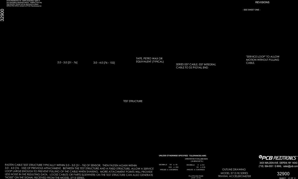
Model 3713D1FE200G. Triaxial DC Accelerometer. Installation and Operating Manual
|
|
|
- Noreen Sanders
- 6 years ago
- Views:
Transcription

1 Model 3713D1FE200G Triaxial DC Accelerometer Installation and Operating Manual For assistance with the operation of this product, contact PCB Piezotronics, Inc. Toll-free: hour SensorLine: Fax: Web:
2 Warranty, Service, Repair, and Return Policies and Instructions The information contained in this document supersedes all similar information that may be found elsewhere in this manual. Total Customer Satisfaction PCB Piezotronics guarantees Total Customer Satisfaction. If, at any time, for any reason, you are not completely satisfied with any PCB product, PCB will repair, replace, or exchange it at no charge. You may also choose to have your purchase price refunded in lieu of the repair, replacement, or exchange of the product. Service Due to the sophisticated nature of the sensors and associated instrumentation provided by PCB Piezotronics, user servicing or repair is not recommended and, if attempted, may void the factory warranty. Routine maintenance, such as the cleaning of electrical connectors, housings, and mounting surfaces with solutions and techniques that will not harm the physical material of construction, is acceptable. Caution should be observed to insure that liquids are not permitted to migrate into devices that are not hermetically sealed. Such devices should only be wiped with a dampened cloth and never submerged or have liquids poured upon them. Repair In the event that equipment becomes damaged or ceases to operate, arrangements should be made to return the equipment to PCB Piezotronics for repair. User servicing or repair is not recommended and, if attempted, may void the factory warranty. Calibration Routine calibration of sensors and associated instrumentation is recommended as this helps build confidence in measurement accuracy and acquired data. Equipment calibration cycles are typically established by the users own quality regimen. When in doubt about a calibration cycle, a good rule of thumb is to recalibrate on an annual basis. It is also good practice to recalibrate after exposure to any severe temperature extreme, shock, load, or other environmental influence, or prior to any critical test. PCB Piezotronics maintains an ISO certified metrology laboratory and offers calibration services, which are accredited by A2LA to ISO/IEC 17025, with full traceablility to N.I.S.T. In addition to the normally supplied calibration, special testing is also available, such as: sensitivity at elevated or cryogenic temperatures, phase response, extended high or low frequency response, extended range, leak testing, hydrostatic pressure testing, and others. For information on standard recalibration services or special testing, contact your local PCB Piezotronics distributor, sales representative, or factory customer service representative. Returning Equipment Following these procedures will insure that your returned materials are handled in the most expedient manner. Before returning any equipment to PCB Piezotronics, contact your local distributor, sales representative, or factory customer service representative to obtain a Return
3 Materials Authorization (RMA) Number. This RMA number should be clearly marked on the outside of all package(s) and on the packing list(s) accompanying the shipment. A detailed account of the nature of the problem(s) being experienced with the equipment should also be included inside the package(s) containing any returned materials. A Purchase Order, included with the returned materials, will expedite the turn-around of serviced equipment. It is recommended to include authorization on the Purchase Order for PCB to proceed with any repairs, as long as they do not exceed 50% of the replacement cost of the returned item(s). PCB will provide a price quotation or replacement recommendation for any item whose repair costs would exceed 50% of replacement cost, or any item that is not economically feasible to repair. For routine calibration services, the Purchase Order should include authorization to proceed and return at current pricing, which can be obtained from a factory customer service representative. Warranty All equipment and repair services provided by PCB Piezotronics, Inc. are covered by a limited warranty against defective material and workmanship for a period of one year from date of original purchase. Contact PCB for a complete statement of our warranty. Expendable items, such as batteries and mounting hardware, are not covered by warranty. Mechanical damage to equipment due to improper use is not covered by warranty. Electronic circuitry failure caused by the introduction of unregulated or improper excitation power or electrostatic discharge is not covered by warranty. Contact Information International customers should direct all inquiries to their local distributor or sales office. A complete list of distributors and offices can be found at Customers within the United States may contact their local sales representative or a factory customer service representative. A complete list of sales representatives can be found at Toll-free telephone numbers for a factory customer service representative, in the division responsible for this product, can be found on the title page at the front of this manual. Our ship to address and general contact numbers are: PCB Piezotronics, Inc Walden Ave. Depew, NY USA Toll-free: (800) hour SensorLine SM : (716) Website: info@pcb.com DOCUMENT NUMBER: DOCUMENT REVISION: B ECN: 17900
4 3710 series DC Accelerometer Operating Guide Introduction This operating guide contains information that will familiarize the user with the basic operation and installation of the 3710 Series MEMS DC Accelerometers. However, it is not intended to cover all of the specific measurement challenges that one may encounter while using the device. Therefore, if you have detailed questions or are unsure of how to properly operate the sensor after reading this Operating Guide, please contact a PCB Application Engineer using our 24-Hour SensorLine TM at Common Applications and Features The 3710 Series MEMS DC Accelerometers achieve true DC response for measuring uniform (or constant) acceleration and low-frequency vibration. For this reason, they are often used to: Perform ride quality assessments of elevators, automobiles, trains, and amusement park rides. Analyze the low frequency characteristics of buildings, bridges, and large aerospace objects. Acquire tilt and orientation data for feedback control and stabilization purposes. Because of the critical nature of these and similar test applications, all 3710 series MEMS DC Accelerometers have been designed and manufactured with the following common characteristics: Rugged, all-welded titanium housing insures reliability and durability in demanding applications and environments. Built-in microelectronics provide conveniently standardized sensitivities and low-noise output signals unmatched by similar sensing technologies. Internal voltage regulator allows sensor to be powered from virtually any unregulated DC voltage source, such as a bench-top power supply or portable battery source. Gas damping extends the upper frequency range, attenuates unwanted high-frequency vibration, and provides stable performance over the entire operating temperature range. Hermetic, multi-pin connector provides a reliable connection even under the harshest environmental conditions. 3.0 Principle of Operation The sensor element of the 3710 series features a proof mass, ring frame, and attachment system between the two. These features are bulk micro machined from the same single-crystal silicon wafer. The movement of the proof mass is directly affected by acceleration applied in the axis of sensitivity. The sensor element is connected as a bridge element in the circuit. The electrical characteristics of one portion of the bridge, increases in value, while the other decreases when exposed to acceleration. This approach minimizes common mode errors and improves non-linearity. A selection of full scale measurement ranges are attained by modifying the stiffness of the suspension system of the proof mass. A high natural frequency is accomplished through the combination of a lightweight proof mass and suspension stiffness. Ruggedness is enhanced through the use of mechanical stops on the two outer wafers to restrict the travel of the proof mass. Damping is used to mitigate high frequency inputs. The sensor elements use squeeze-film gas damping that is nominally 0.7 critical. This is the result of the movement of the proof mass pressing on the gas in the gap between it and the outer sensor layer. Damping helps prevent the output of the accelerometer from becoming saturated, as would happen when the resonance of an accelerometer with no damping is excited by random vibration. The advantage of gas damping over liquid damping is that it is minimally affected by temperature changes. The 3710 series accelerometers contain conditioning circuitry that provides a high sensitivity output. This IC also provides compensation of zero bias and sensitivity errors over temperature using a continuous piecewise straight line correction engine. An on-board voltage regulator allows a typical excitation range of 6 to 30 VDC with <10 ma current draw. The 3710 series features a ± 2 V Full Scale zero based output referenced to power ground. A negative voltage generator provides a sufficient signal swing for negative acceleration outputs with a positive voltage swing of +4.0 V accommodating positive accelerations. An automated calibration step is conducted at the completion of the accelerometer assembly at discrete temperatures over the specified operating temperature range. The IC features an on-chip temperature sensor for accurate thermal corrections. Manual Number: Manual Revision: C ECR Number: 36283
5 3710 series DC Accelerometer Operating Guide Typical Measurement System The 3710 series DC Accelerometers are available in a uniaxial or triaxial package, with the triaxial model being the 3713 version. The output signal is routed to follow-on signal conditioning via a hermetic four-pin receptacle and associated cable assembly, Model 010 series for the 3711 uniaxial version, and Model 037 series nine-pin cable assembly, for the 3713 triaxial version. Since the High Sensitivity DC Accelerometers contain a built-in voltage regulator, they may be powered from virtually any 6 to 30 Vdc power source without adversely affecting sensor performance. PCB signal conditioners available are Model 445B01, a single-channel, line powered, signal conditioner for the uniaxial 3711series DC accelerometers and Model 478A05, a three-channel, line-powered signal conditioner for the triaxial 3713 accelerometer. Consult PCB Application Engineering for additional signal conditioning options. The output from the signal conditioner is typically routed to readout instrumentation such as oscilloscopes or various model data acquisition instruments. 5.0 Sensor Installation When choosing an installation technique, be certain to carefully examine the different application characteristics that may affect sensor performance. Characteristics such as mounting location may limit the use of large mounting blocks or the amplitude range may necessitate the use of a stud mount rather than using adhesive. A summary of the recommended mounting methods is provided below. Stud Mount: Recommended for permanent mount applications or in test situations that require a rugged or secure installlation. The necessary information, including surface finish, mounting hole dimensions, and recommended mounting torque for installing the sensor is listed on the enclosed Sensor Installation Drawing. It is recommended that an experienced technician or machinist with good machining capabilities adequately prepare the surface. Adhesive Mount: Recommended for temporary mounting of the sensor or when the test object surface cannot be properly prepared for stud mounting. Wax works well for temporary mount applications under conditions where the operating temperature will not melt the wax or the acceleration levels will not dislodge the sensor from the test object. Cyanoacrylatebased, quick-bonding adhesives provide a quick mounting method, while two-part epoxies can be used for a more secure mount. To remove an adhesively mounted sensor, it is best to place an open-ended wrench over the sensor and twist it to shear the adhesive bond. Striking the sensor with a hammer or other object may permanently damage the sensor. Easy Mount Clip: Recommended when frequent installation and removal of Series 3710 series accelerometers is desired. The Easy-Mount Clip can either be stud mounted or adhesively mounted to the test structure. (If adhesively mounting the clip, detach the sensor from the clip first, as excessive adhesive may creep through the mounting holes and adhere to the sensor. This will make separation and removal from the clip difficult.) Once the Easy-Mount Clip has been attached to the test structure, the sensor can be easily snapped into and out of the clip. Over time, the Easy-Mount Clip must be replaced as it will wear-out and eventually lose its ability to securely hold the sensor. 6.0 Powering The 3710 Series contains built-in microelectronics that will operate from any PCB Series 445 or Series 478 Sensor Signal Conditioner. These signal conditioners provide the necessary voltage and current required for all of the powering options available on the 3710 series. The 3710 series may also be powered by other voltage sources such as DC voltage laboratory supplies, automotive or marine batteries, or low-voltage supplies designed for powering PC Board components. If you decide to not use a Series 445 or 478 Series Signal Conditioner, insure that the source provides power within the excitation voltage range listed on the specification sheet for that model. It is important to note that since the accelerometers contain a built-in voltage regulator, precise calibration of the power source is generally not required. 7.0 Operation After the sensor has been installed and the cable connected for proper operation, there are a couple of measurement points to take note of: To take advantage of the DC response of the accelerometer, the readout device must be in a DC coupled state. Consult the appropriate manufacturer or product manual for your readout device for details. Because the 3710 series can measure static (constant) accelerations, the DC offset voltage will be affected by the positional alignment relative to the Earth s gravity. In other words, when the sensor is mounted perpendicular with the Earth s surface, the offset will equal that as specified on the calibration certificate for zero-g offset voltage. If the sensor is mounted parallel with the Earth s surface, the sensor will be experiencing 1 g of acceleration and the offset voltage will increase by the sensitivity of the accelerometer. Manual Number: Manual Revision: C ECR Number: 36283
6 3710 series DC Accelerometer Operating Guide 3 If the sensor is extended, in the case of an integral cable sensor, or a cable length other than 10ft is used, in the case of sensor with an integral connector, the offset voltage will change. To determine the accelerometer s offset, rotate the unit 90 so that the sensor is on its side with the sensing axis perpendicular to Earth s gravity and record the DC output. This value is the new zero-g offset voltage. To insure that ground loops are not induced, the shield should only be terminated at one end. Typically, the shield of the cable is tied to sensor housing. If the sensor is mounted with an isolation pad (or other form of electrical isolation) from the test structure, then the shield should be tied to signal ground at the instrumentation end. Otherwise, leave the cable shield floating or not connected at the instrumentation end. 8.0 Sensor Verification If the sensor has been handled in a rough manner or before a critical measurement application, it is a good idea to verify that the sensor s sensitivity is still within specification. An accurate static calibration of the 3710 series can be performed using the Earth s Gravitational Field as a reference. The sensor can simply be flipped (rotated 180 ) in the Earth s Gravity to obtain the scaling factor (sensitivity) and DC offset. First, place the accelerometer in a +1g orientation so that the base is resting on the table and the model number is facing up. The sensing axis will be parallel with the Earth s gravity with the sensor experiencing +1g acceleration. Record the DC output by using a DVM. Then rotate the sensor 180 so that the sensor is inverted (the top of the sensor is resting on the table) and the sensor is experiencing 1g acceleration. Record the DC output.. To calculate the sensitivity of the accelerometer refer to equation 8.1. A repair or replacement quotation is available at no charge. Before returning equipment for repair, it is recommended that the user confer with a factory application engineer (or international representative) to first troubleshoot the problem Return Procedure To expedite the repair process, contact a factory application engineer to obtain a Return Material Authorization (RMA) number prior to sending equipment to the factory. Please have information, such as model number, serial number and description of the problem, available. Customers outside the U.S. should consult their local PCB distributor for information on returning equipment. For exceptions to this guideline, please contact the International Sales department to request shipping instructions and an RMA. For further assistance, please call (716) or fax us at (716) You may also receive assistance via at sales@pcb.com or visit our web site at Customer Service / Warranty The employees of PCB strive to provide superior, unmatched customer service. Should you at any time find yourself dissatisfied with any PCB product for any reason, consult a factory Application Engineer or local representative/distributor to discuss repair, refund, or exchange procedures. When unexpected measurement problems arise, call our 24- hour Sensor Line TM at (716) to discuss your immediate dynamic instrumentation needs with a Factory Representative. Sensititvity = (+1g) (-1g) Eq Sensor Calibration Due to ISO 9001, ISO Guide 25, or other contractual requirements, it may become necessary to send the accelerometer back to PCB for recalibration. In this case, a complete backto-back frequency response test will be performed and the zero-g offset voltage will be checked with NIST traceable equipment Maintenance and Repair Because of the sophisticated nature of PCB instrumentation, field repair of the equipment is not recommended. Most PCB sensors are of modular construction and are factory repairable. Manual Number: Manual Revision: C ECR Number: 36283


7
8
9
10
Model 356B40. Sell 356B41. Installation and Operating Manual
 Model 356B40 Sell 356B41 Installation and Operating Manual For assistance with the operation of this product, contact PCB Piezotronics, Inc. Toll-free: 800-828-8840 24-hour SensorLine: 716-684-0001 Fax:
Model 626B01. Low Frequency Industrial ICP Accelerometer. Installation and Operating Manual
 Model 626B01 Low Frequency Industrial ICP Accelerometer Installation and Operating Manual For assistance with the operation of this product, contact PCB Piezotronics, Inc. Toll-free: 800-959-4464 24-hour
Model 629A31. Precision Triaxial Industrial ICP Accelerometer. Installation and Operating Manual
 Model 629A31 Precision Triaxial Industrial ICP Accelerometer Installation and Operating Manual For assistance with the operation of this product, contact PCB Piezotronics, Inc. Toll-free: 800-959-4464
Model 600A13. Very High Temperature ICP Accelerometer Kit. Installation and Operating Manual
 Model 600A13 Very High Temperature ICP Accelerometer Kit Installation and Operating Manual For assistance with the operation of this product, contact PCB Piezotronics, Inc. Toll-free: 800-959-4464 24-hour
Model 640B ma Output Velocity Sensor. Installation and Operating Manual
 Model 640B02 4-20 ma Output Velocity Sensor Installation and Operating Manual For assistance with the operation of this product, contact PCB Piezotronics, Inc. Toll-free: 800-959-4464 24-hour SensorLine:
Model A. DIN Rail Strain Gage Conditioner. Installation and Operating Manual
 Model 8161-011A DIN Rail Strain Gage Conditioner Installation and Operating Manual For assistance with the operation of this product, contact PCB Piezotronics, Inc. Toll-free: 800-828-8840 24-hour SensorLine:
Model 3713E1150G. Triaxial DC Response Accelerometer. Installation and Operating Manual
 Model 373E50G Triaxial DC Response Accelerometer Installation and Operating Manual For assistance with the operation of this product, contact PCB Piezotronics, Inc. Toll-free: 800-88-8840 4-hour SensorLine:
Model C STRAIN GAGE LOAD CELL. Installation and Operating Manual
 Model 1631-01C STRAIN GAGE LOAD CELL Installation and Operating Manual For assistance with the operation of this product,contact: PCB Load & Torque, Inc. Toll-free: 866-684-7107 24-hour SensorLine : 716-684-0001
Model A. Reaction Torque Sensor. Installation and Operating Manual
 Model 2508-01A Reaction Torque Sensor Installation and Operating Manual For assistance with the operation of this product,contact: PCB Load & Torque, Inc. Toll-free: 866-684-7107 24-hour SensorLine : 716-684-0001
Model 3711D1FA3G. DC Accelerometer. Installation and Operating Manual
 Model 3711D1FA3G DC Accelerometer Installation and Operating Manual For assistance with the operation of this product, contact PCB Piezotronics, Inc. Toll-free: 800-828-8840 24-hour SensorLine: 716-684-0001
Model HAND TORQUE WRENCH. Installation and Operating Manual
 Model 027125-07012 HAND TORQUE WRENCH Installation and Operating Manual For assistance with the operation of this product, contact PCB Piezotronics, Inc. Toll-free: 800-828-8840 24-hour SensorLine: 716-684-0001
Sensors for Research & Development and Machinery Health Monitoring
 P C B P I E Z O T R O N I C S, I N C. Sensors for Research & Development and Machinery Health Monitoring PCB.com +1.716.684.0001 IMI-SENSORS.com +1.716.684.0003 P C B P I E Z O T R O N I C S, I N C. PLATINUM
Sensors for Research & Development and Machinery Health Monitoring
 P C B P I E Z O T R O N I C S, I N C. Sensors for Research & Development and Machinery Health Monitoring PCB.com 800.828.8840 IMI-SENSORS.com 800.959.4464 P C B P I E Z O T R O N I C S, I N C. PLATINUM
INSTRUCTION MANUAL. IM7298, Revision A ( )
") INSTRUCTION MANUAL For Model 7298 Triaxial Microtron Variable Capacitance Accelerometer IM7298, Revision A (07-10-13) General Overview The Endevco Model 7298 Triaxial Microtron accelerometer is a rugged,
INSTRUCTION MANUAL For Model 7298 Triaxial Microtron Variable Capacitance Accelerometer IM7298, Revision A (07-10-13) General Overview The Endevco Model 7298 Triaxial Microtron accelerometer is a rugged,
Vehicle & Component Durability Sensors Accelerometers, Load Cells, Force Sensors, and Signal Conditioners
 WWW.PCB.COM Vehicle & Component Durability Sensors Accelerometers, Load Cells, Force Sensors, and Signal Conditioners Automotive Sensors Division Toll-Free in USA 888-684-0014 716-684-0001 www.pcb.com
GUIDE TO DYNAMIC FORCE SENSORS
 SENSORS FOR RESEARCH & DEVELOPMENT WHITE PAPER #30 GUIDE TO DYNAMIC FORCE SENSORS www.pcb.com info@pcb.com 800.828.8840 MTS SYSTEMS CORPORATION For Additional Specification Information Visit www.pcb.com
NEW FROM PCB. Sensors & Instrumentation for Measuring Vibration, Sound, Torque, Pressure, Force, and Strain
 SENSORS FOR RESEARCH & DEVELOPMENT AND MACHINERY HEALTH MONITORING NEW FROM PCB Sensors & Instrumentation for Measuring Vibration, Sound, Torque, Pressure, Force, and Strain www.pcb.com info@pcb.com 800.828.8840
OPERATING GUIDE MODEL 3093M32 MINIATURE HIGH SENSITIVITY TRIAXIAL LIVM ACCELEROMETER WITH SINGLE 4-PIN CONNECTOR INTERNALLY CASE GROUND ISOLATED
 Dytran Instruments, Inc. 21592 Marilla St. Chatsworth, CA 91311 Ph: 818-700-7818 Fax: 818-700-7880 www.dytran.com email: info@dytran.com OG3093M32.docx OPERATING GUIDE MODEL 3093M32 MINIATURE HIGH SENSITIVITY
INDUSTRIAL VIBRATION SENSOR SELECTION MADE EASY
 SENSORS FOR RESEARCH & DEVELOPMENT WHITE PAPER #28 INDUSTRIAL VIBRATION SENSOR SELECTION MADE EASY NINE QUESTIONS TO SUCCESSFULLY IDENTIFY THE SOLUTION TO YOUR APPLICATION www.pcb.com info@pcb.com 800.828.8840
WHITE PAPER. Continuous Condition Monitoring with Vibration Transmitters and Plant PLCs
 WHITE PAPER Continuous Condition Monitoring with Vibration Transmitters and Plant PLCs Visit us online at www.imi-sensors.com Toll-Free in USA 800-959-4464 716-684-0003 Continuous Condition Monitoring
Motor Vibration. Detect Mechanical & Electrical Motor Faults with Vibration Monitoring Instrumentation. IMI Sensors - A PCB Piezotronics Division
 IMI Sensors - A PCB Piezotronics Division Motor Vibration Detect Mechanical & Electrical Motor Faults with Vibration Monitoring Instrumentation visit us at www.pcb.com/imi-sensors Predictive Maintenance
NEW FROM PCB. Sensors & Instrumentation for Measuring Vibration, Sound, Torque, Pressure, Force, and Strain
 SENSORS FOR RESEARCH & DEVELOPMENT AND MACHINERY HEALTH MONITORING NEW FROM PCB Sensors & Instrumentation for Measuring Vibration, Sound, Torque, Pressure, Force, and Strain www.pcb.com Info@PCB.com 800.828.8840
General Signal Conditioning Guide An Introduction to the Operation of ICP and Charge Output Sensors and Instrumentation
 Vibration Pressure Force Strain General Signal Conditioning Guide An Introduction to the Operation of ICP and Charge Output Sensors and Instrumentation General Signal Conditioning Guide P I E Z O E L E
Operating Manual. Model 832 & 832M1 Accelerometer
 Model 832 & 832M1 Accelerometer Measurement Specialties, Inc. Vibration Sensors Design Center 32 Journey, Suite 150 Aliso Viejo, CA 92656 USA Tel: 949-716-7324 www.meas-spec.com vibration@meas-spec.com
TIPS FROM TECHS. Understanding Current Output Signals: RMS, Peak and True Peak. Energy & Power Generation
 TIPS FROM TECHS Understanding Current Output Signals: RMS, Peak and True Peak Energy & Power Generation Written By: Meredith Christman, Product Marketing Manager, IMI division of PCB Piezotronics Visit
Test & Measurement Sensors & Instrumentation
 Test & Measurement Sensors & Instrumentation Acceleration & Vibration, Acoustics, Pressure, Force, Load, Strain, Shock & Torque 24-hour SensorLine SM 716-684-0001 www.pcb.com www.pcb.com Test & Measurement
Technical Information
 Technical Information Introduction to force sensors Driving long cable lengths Conversions, article reprints, glossary INTRODUCTION TO QUARTZ FORCE SENSORS Quartz Force Sensors are well suited for dynamic
Mounting Instructions
 Mounting Instructions This technical note describes basic installation techniques for accelerometers and other vibration sensors. It will allow qualified field technicians to install vibration sensors
26 Endevco Isotron accelerometers
 Isotron accelerometers Typical applications > Aircraft flight testing > Ground vibration testing > Automotive ride quality testing > Product testing > Quality assurance > Research and development > Test
CONTINUOUS CONDITION MONITORING WITH VIBRATION TRANSMITTERS AND PLANT PLCS
 SENSORS FOR MACHINERY HEALTH MONITORING WHITE PAPER #47 CONTINUOUS CONDITION MONITORING WITH VIBRATION TRANSMITTERS AND PLANT PLCS www.pcb.com/imi-sensors imi@pcb.com 800.828.8840 Continuous Condition
Troubleshooting accelerometer installations
 Troubleshooting accelerometer installations Accelerometer based monitoring systems can be tested to verify proper installation and operation. Testing ensures data integrity and can identify most commonly
vibrati vibration solutions by sensor type Measurement Specialties brings more than twenty years of
 vibration solutions by sensor type Measurement Specialties brings more than twenty years of vibrati experience in the design and manufacture of s and gyros based on our proprietary Micro-ElectroMechanical
GE Energy Operating Guide Series Industrial Transmitter, with Dynamic Signal Sensor
 GE Energy Operating Guide 177230 Series Industrial Transmitter, with Dynamic Signal Sensor Part Number 37543 Rev. C December 2007 Seismic Transmitter Operating Guide Copyright 2007. General Electric Company.
Improved Low Cost ±5 g Dual-Axis Accelerometer with Ratiometric Analog Outputs MXR7305VF
 Improved Low Cost ±5 g Dual-Axis Accelerometer with Ratiometric Analog Outputs MXR7305VF FEATURES Dual axis accelerometer fabricated on a single CMOS IC Monolithic design with mixed mode signal processing
TRANSDUCER IN-LINE AMPLIFIER
 TRANSDUCER IN-LINE Voltage Model AMPLIFIER 2080 Arlingate, Columbus, Ohio 43228, (614) 850-5000 Sensotec, Inc. 2080 Arlingate Lane Columbus, Ohio 43228 Copyright 1995 by Sensotec, Inc. all rights reserved
TETRIS 1000 High Impedance Active Probe. Instruction Manual
 TETRIS 1000 High Impedance Active Probe Instruction Manual Copyright 2015 PMK GmbH All rights reserved. Information in this publication supersedes that in all previously published material. Specifications
CONSIDERATIONS FOR ACCELEROMETER MOUNTING ON MOTORS
 SENSORS FOR MACHINERY HEALTH MONITORING WHITE PAPER #49 CONSIDERATIONS FOR ACCELEROMETER MOUNTING ON MOTORS ACCELEROMETER SELECTION AND MOUNTING RECOMMENDATIONS FOR VIBRATION ANALYSIS OF MOTORS IN THE
Load Cell Accessories and Services
 Load Cell Accessories and Services Highlights Strain gage signal conditioners Cable assemblies Mounting accessories Calibration services PCB Piezotronics, Inc. Toll-Free in USA 888-684-0004 716-684-0001
AC/DC Current Oscilloscope Probe Model SL261
 AC/DC Current Oscilloscope Probe Model SL261 USER MANUAL I ZERO 100 mv/a 10 mv/a OFF Statement of Compliance Chauvin Arnoux, Inc. d.b.a. AEMC Instruments certifies that this instrument has been calibrated
NEW FROM PCB. Sensors & Instrumentation for Measuring Vibration, Sound, Torque, Pressure, Force, and Strain
 SENSORS AND SYSTEMS FOR RESEARCH & DEVELOPMENT AND MACHINERY HEALTH MONITORING NEW FROM PCB Sensors & Instrumentation for Measuring Vibration, Sound, Torque, Pressure, Force, and Strain www.pcb.com MTS
Model 134A24 Tourmaline ICP pressure bar, 1000 psi, 5 mv/psi, 0.2 microsecond rise. Installation and Operating Manual
 Model 134A24 Tourmaline ICP pressure bar, 1000 psi, 5 mv/psi, 0.2 microsecond rise Installation and Operating Manual This manual contains the 402A installation and operating manuals that comprise a Model
FST Series HUMIDITY-TEMPERATURE TRANSMITTERS INSTRUCTION MANUAL
 FST Series HUMIDITY-TEMPERATURE TRANSMITTERS INSTRUCTION MANUAL 20020628 CONTENTS DESCRIPTION... 3 OPERATION... 4 Power Supply...4 Output Range...4 Temperature Operating Range and Temperature Limits...4
Installation of vibration sensors
 Installation of vibration sensors This technical note describes basic installation techniques for accelerometers and other vibration sensors. It will allow qualified field technicians to install vibration
Reference Diagram IDG-300. Coriolis Sense. Low-Pass Sensor. Coriolis Sense. Demodulator Y-RATE OUT YAGC R LPY C LPy ±10% EEPROM TRIM.
 FEATURES Integrated X- and Y-axis gyro on a single chip Factory trimmed full scale range of ±500 /sec Integrated low-pass filters High vibration rejection over a wide frequency range High cross-axis isolation
Dytran Instruments, Inc. 1
 Dytran Instruments, Inc. 1 Installed HUMS Base Dytran sensors are installed on the following airframes for HUMS applications Dytran Instruments, Inc. 2 MH60 Blackhawk A119 AS350 Bell 412 AH-64 MH47 Introduction
Integrated Dual-Axis Gyro IDG-1004
 Integrated Dual-Axis Gyro NOT RECOMMENDED FOR NEW DESIGNS. PLEASE REFER TO THE IDG-25 FOR A FUTIONALLY- UPGRADED PRODUCT APPLICATIONS GPS Navigation Devices Robotics Electronic Toys Platform Stabilization
MEAS Silicon MEMS Piezoresistive Accelerometer and its Benefits
 MEAS Silicon MEMS Piezoresistive Accelerometer and its Benefits Piezoresistive Accelerometers 1. Bonded Strain Gage type (Gages bonded to metal seismic mass using epoxy) Undamped circa 1950 s Fluid (oil)
Operator s Manual. PP016 Passive Probe
 Operator s Manual PP016 Passive Probe 2017 Teledyne LeCroy, Inc. All rights reserved. Unauthorized duplication of Teledyne LeCroy documentation materials is strictly prohibited. Customers are permitted
Worldwide Manufacturer of Gas Detection Solutions. Transmitter EC 23. Operation Manual
 Worldwide Manufacturer of Gas Detection Solutions Transmitter EC 23 Operation Manual Table of Contents For Your Safety...4 General Description...4 Electrical Connections...5 Zero Point Adjustment...5
45EMD Portable Calibrator User Manual
 Trig-Tek 45EMD Portable Calibrator User Manual Publication No. 980958 Rev. B Astronics Test Systems Inc. 4 Goodyear, Irvine, CA 92618 Tel: (800) 722-2528, (949) 859-8999; Fax: (949) 859-7139 atsinfo@astronics.com
731A seismic accelerometer and P31 power unit/amplifier Operating guide
 731A seismic accelerometer and P31 power unit/amplifier Operating guide Caution: This manual should be read carefully before installation. Wilcoxon Sensing Technologies 8435 Progress Drive, Frederick,
Non-Submersible Industrial Pressure Transducer
 Non-Submersible Industrial Pressure Transducer KPSI Transducers Series 27, 28, 30 FEATURES Custom Pressure Ranges up to 2000 (13,790 kpa) Accuracy to ±0.10% FS Analog Outputs of 4-20 ma or VDC Welded 316
UNDERSTANDING TORQUE -ANGLE SIGNATURES OF BOLTED JOINTS
 SENSORS FOR RESEARCH & DEVELOPMENT WHITE PAPER #23 UNDERSTANDING TORQUE -ANGLE SIGNATURES OF BOLTED JOINTS THREADED FASTENER TORQUE-ANGLE CURVE ANALYSIS Written By Jeff Drumheller www.pcb.com info@pcb.com
AMP-13 OPERATOR S MANUAL
 AMP-13 OPERATOR S MANUAL Version 2.0 Copyright 2008 by Vatell Corporation Vatell Corporation P.O. Box 66 Christiansburg, VA 24068 Phone: (540) 961-3576 Fax: (540) 953-3010 WARNING: Read instructions carefully
TRANSDUCER IN-LINE AMPLIFIER
 TRANSDUCER IN-LINE Bi-Polar Model AMPLIFIER 2080 Arlingate Lane, Columbus, Ohio 43228 (614) 850-5000 Sensotec, Inc. 2080 Arlingate Lane Columbus, Ohio 43228 Copyright 1995 by Sensotec, Inc. all rights
Model MV106J/MV116J. ±10nVdc to ±11Vdc Precision DC Voltage Standard Source. Operating Manual
 Model MV106J/MV116J ±10nVdc to ±11Vdc Precision DC Voltage Standard Source Operating Manual This page intentionally left blank. MV 106 & MV116 OPERATORS MANUAL Serial No. Win-man\mvman.wpd This page intentionally
MXD6235Q. Ultra High Performance ±1g Dual Axis Accelerometer with Digital Outputs FEATURES
 Ultra High Performance ±1g Dual Axis Accelerometer with Digital Outputs MXD6235Q FEATURES Ultra Low Noise 0.13 mg/ Hz typical RoHS compliant Ultra Low Offset Drift 0.1 mg/ C typical Resolution better than
670K9 SORtrax Level Transmitter
 SORtrax is a 4-20 ma continuous level transmitter. It produces a 4-20mA current superimposed on the 12-55 VDC loop supply lines. The 4-20mA current is proportional to the level sensed by the instrument.
OPERATION & SERVICE MANUAL FOR FC 110 AC POWER SOURCE
 OPERATION & SERVICE MANUAL FOR FC 100 SERIES AC POWER SOURCE FC 110 AC POWER SOURCE VERSION 1.3, April 2001. copyright reserved. DWG No. FC00001 TABLE OF CONTENTS CHAPTER 1 INTRODUCTION... 1 1.1 GENERAL...
Global Water Instrumentation, Inc.
 Global Water Instrumentation, Inc. 151 Graham Road P.O. Box 9010 College Station, TX 77842-9010 T: 800-876-1172 Int l: (979) 690-5560, F: (979) 690-0440 Barometric Pressure: WE100 Solar Radiation: WE300
Model 352A25. Miniature, lightweight (0.6 gm) ceramic shear ICP accel., 2.5 mv/g, 1 to. Installation and Operating Manual
 ceramic shear ICP accel., 2.5 mv/g, 1 to. Installation and Operating Manual") Model 352A25 Miniature, lightweight (0.6 gm) ceramic shear ICP accel., 2.5 mv/g, 1 to Installation and Operating Manual For assistance with the operation of this product, contact PCB Piezotronics, Inc.
Model 352A25 Miniature, lightweight (0.6 gm) ceramic shear ICP accel., 2.5 mv/g, 1 to Installation and Operating Manual For assistance with the operation of this product, contact PCB Piezotronics, Inc.
Anthony Chu. Basic Accelerometer types There are two classes of accelerometer in general: AC-response DC-response
 Engineer s Circle Choosing the Right Type of Accelerometers Anthony Chu As with most engineering activities, choosing the right tool may have serious implications on the measurement results. The information
Model 3713B11200G. Triaxial DC Response Accelerometer. Installation and Operating Manual
 Model 37300G Triaxial DC Response Accelerometer Installation and Operating Manual For assistance with the operation of this product, contact PC Piezotronics, Inc. Toll-free: 800-88-8840 4-hour SensorLine:
Model 3713B1130G. Triaxial DC Response Accelerometer. Installation and Operating Manual
 Model 37330G Triaxial DC Response Accelerometer Installation and Operating Manual For assistance with the operation of this product, contact PC Piezotronics, Inc. Toll-free: 800-88-8840 4-hour SensorLine:
PRODUCT DATA. Piezoelectric Accelerometer Miniature Triaxial DeltaTron Accelerometers Types 4524, 4524 B
 PRODUCT DATA Piezoelectric Accelerometer Miniature Triaxial DeltaTron Accelerometers Types 4524, 4524 B Types 4524 and 4524 B are lightweight triaxial piezoelectric OrthoShear accelerometers, each with
MXD6125Q. Ultra High Performance ±1g Dual Axis Accelerometer with Digital Outputs FEATURES
 Ultra High Performance ±1g Dual Axis Accelerometer with Digital Outputs MXD6125Q FEATURES Ultra Low Noise 0.13 mg/ Hz typical RoHS compliant Ultra Low Offset Drift 0.1 mg/ C typical Resolution better than
Integrated Dual-Axis Gyro IDG-500
 Integrated Dual-Axis Gyro FEATURES Integrated X- and Y-axis gyros on a single chip Two separate outputs per axis for standard and high sensitivity: X-/Y-Out Pins: 500 /s full scale range 2.0m/ /s sensitivity
742A Series Resistance Standards
 742A Series Resistance Standards Instruction Manual PN 850255 September 1988 Rev. 1, 4/89 1988-2015 Fluke Corporation. All rights reserved. All product names are trademarks of their respective companies.
Electromagnetic shakers operating guide Models F3, F4, F5B, F10
 Electromagnetic shakers operating guide Models F3, F4, F5B, F10 Caution: This manual should be read carefully before installation WARNING: OPERATION OF THE ELECTROMAGNETIC SHAKER IS SAFE WHEN THE INSTRUCTIONS
CHOOSING THE RIGHT TYPE OF ACCELEROMETER
 As with most engineering activities, choosing the right tool may have serious implications on the measurement results. The information below may help the readers make the proper accelerometer selection.
INSTRUCTION MANUAL LKG 601 Electrical Safety Analyzer
 INSTRUCTION MANUAL LKG 601 Electrical Safety Analyzer 110 Toledo Street Farmingdale, NY 11735 USA http://www.netech.org 510-USER-Manual Rev3 10/29/2007 Dear User, We appreciate your purchase of the LKG
M1 Series. Humidity - Temperature Transmitter INSTRUCTION MANUAL
 M1 Series Humidity - Temperature Transmitter INSTRUCTION MANUAL 20031110 -2- CONTENTS Overview... 3 Operation... 4 Power supply... 4 Operating range and limits... 4 Temperature compensation of the humidity
Roline L1 Series. Humidity - Temperature Transmitters INSTRUCTION MANUAL
 Roline L1 Series Humidity - Temperature Transmitters INSTRUCTION MANUAL 20030314 CONTENTS Overview... 3 Operation... 5 Power supply... 5 Operating range and limits... 5 Temperature compensation of the
Torque Sensor Accessories and Services
 ------------------- Torque Sensor Accessories and Services Highlights Strain gage signal conditioners Cable assemblies Speed sensors Shunt calibration modules and thermocouples Calibration services PCB
MEASURING MACHINES. Pratt & Whitney METROLOGY LABORATORY. Measurement Systems, Inc.
 METROLOGY LABORATORY Pratt & Whitney Measurement s, Inc. METROLOGY LABORATORY The Standard of Accuracy Pratt & Whitney Metrology Laboratory Machines are the standard to which all other gages are held subordinate.
INSTRUCTION MANUAL INF Fax: (503)
") INSTRUCTION MANUAL INF151 1-800-547-5740 Fax: (503) 643-6322 www.ueiautomotive.com email: info@ueitest.com Introduction Congratulations on your purchase of the INF151 infrared thermometer. Like all UEi
INSTRUCTION MANUAL INF151 1-800-547-5740 Fax: (503) 643-6322 www.ueiautomotive.com email: info@ueitest.com Introduction Congratulations on your purchase of the INF151 infrared thermometer. Like all UEi
MXD7210GL/HL/ML/NL. Low Cost, Low Noise ±10 g Dual Axis Accelerometer with Digital Outputs
 FEATURES Low cost Resolution better than 1milli-g at 1Hz Dual axis accelerometer fabricated on a monolithic CMOS IC On chip mixed signal processing No moving parts; No loose particle issues >50,000 g shock
GB-AVSTOR5 Ceiling Equipment Storage Box with Pipe Coupler
 Ceiling Equipment Storage Box with Pipe Coupler INSTALLATION INSTRUCTIONS CREATING POSITIVE CUSTOMER EXPERIENCES 9534-500-021-00 Contents Weight Limit... 2 Warning Statements... 2 Installation Tools...
41P Portable Calibrator User Manual
 Trig-Tek 41P Portable Calibrator User Manual Publication No. 980961 Rev. A Astronics Test Systems Inc. 4 Goodyear, Irvine, CA 92618 Tel: (800) 722-2528, (949) 859-8999; Fax: (949) 859-7139 atsinfo@astronics.com
Investigate and Optimize Your Structures with Kistler's Modal Portfolio
 Investigate and Optimize Your Structures with Kistler's Modal Portfolio Source: NASA Modal Analysis Accelerometers, Impact Hammers, Impedance Heads, Force Sensors and Electronics for Your Modal Analysis
A53106 SERIES DC-TO-DC CONVERTER
 INSTALLATION & MAINTENANCE A53106 SERIES DC-TO-DC CONVERTER AUGUST 2011, REVISED AUGUST 2014 DOCUMENT NO. COM-00-04-20 VERSION C.1 Siemens Industry, Inc., Rail Automation 9568 Archibald Ave., Suite 100,
Embedded Surface Mount Triaxial Accelerometer
 Embedded Surface Mount Triaxial Accelerometer Robert D. Sill Senior Scientist PCB Piezotronics Inc. 951 Calle Negocio, Suite A San Clemente CA, 92673 (877) 679 0002 x2954 rsill@pcb.com Abstract 18566 59
PSW-002. Fiber Optic Polarization Switch. User Guide
 PSW-002 Fiber Optic Polarization Switch User Guide Version: 1.0 Date: May 30, 2014 General Photonics, Incorporated is located in Chino California. For more information visit the company's website at: www.generalphotonics.com
Aero Support Ltd, 70 Weydon Hill Road, Farnham, Surrey, GU9 8NY, U.K.
 4-170 Piezoelectric Accelerometer The CEC 4-170 accelerometer is a self-generating, piezoelectric accelerometer designed for medium temperature vibration measurement applications. This instrument provides
Model 7000 Low Noise Differential Preamplifier
 Model 7000 Low Noise Differential Preamplifier Operating Manual Service and Warranty Krohn-Hite Instruments are designed and manufactured in accordance with sound engineering practices and should give
TECHNICAL MANUAL. SERIES AP5103 DIN-Rail DC Strain Gage Conditioner ISO 9001/AS9100
 TECHNICAL MANUAL SERIES AP5103 DIN-Rail DC Strain Gage Conditioner ISO 9001/AS9100 Due to the nature of technology, changes are inevitable. For latest technical specifications, see our website. Copyright
Frequency Response Analyzers for Stability Analysis and Power Electronics Performance Testing
 Frequency Response Analyzers for Stability Analysis and Power Electronics Performance Testing Product Features Since 1979, Venable Instruments has been focused on one goal: bringing the most versatile,
Model TLD352A57. ICP Accelerometer. Installation and Operating Manual
 Model TLD352A57 ICP Accelerometer Installation and Operating Manual For assistance with the operation of this product, contact PCB Piezotronics, Inc. Toll-free: 800-828-8840 24-hour SensorLine: 716-684-0001
Integrated Dual-Axis Gyro IDG-1215
 Integrated Dual-Axis Gyro FEATURES Integrated X- and Y-axis gyros on a single chip ±67 /s full-scale range 15m/ /s sensitivity Integrated amplifiers and low-pass filter Auto Zero function Integrated reset
1510A PRECISION SIGNAL SIMULATOR
 A worldwide leader in precision measurement solutions Portable signal source for calibrating electronic equipment and machinery monitoring systems. 1510A PRECISION SIGNAL SIMULATOR Voltage Signals Charge
Models Z7, Z11, Z602WA and Z820WA Impedance head operating guide
 Models Z7, Z11, Z602WA and Z820WA Impedance head operating guide Wilcoxon Sensing Technologies 8435 Progress Drive, Frederick, MD 21701, USA Amphenol (Maryland), Inc d/b/a Wilcoxon Sensing Technologies
Miniature silicon-on-insulator pressure transducer for absolute pressure measurement at 260 C
 Miniature silicon-on-insulator pressure transducer for absolute pressure measurement at 260 C PMiniature silicon-on-insulator pressure transducer for absolute pressure measurement at 260 C Abstract A miniature,
INSTRUCTION MANUAL LKG
 INSTRUCTION MANUAL LKG 610 Electrical Safety Analyzer With 10 ECG Connectors 110 Toledo Street Farmingdale, NY 11735 USA Homepage: www.netech.org Dear User, We appreciate your purchase of the LKG 610 Electrical
LOW COST SDI 2210, 2260 & 2266 HIGH PERFORMANCE SDI 2220 & 2276
 LOW COST & HIGH PERFORMANCE 1-AXIS DC ACCELEROMETER MODULES Low Noise: 10 μg Hz Typical for ±2g Full Scale Versions -55 to +125 C Operating Temperature Range Flexible +8 to +32 VDC Power Excellent Long
CM605. User Manual AC/DC LOW CURRENT CLAMP-ON METER ENGLISH
 AC/DC LOW CURRENT CLAMP-ON METER CM605 ENGLISH User Manual Statement of Compliance Chauvin Arnoux, Inc. d.b.a. AEMC Instruments certifies that this instrument has been calibrated using standards and instruments
INSTRUCTION MANUAL For LINE IMPEDANCE STABILIZATION NETWORK. Model LI khz to 10 MHz
 Page 1 of 10 INSTRUCTION MANUAL For LINE IMPEDANCE STABILIZATION NETWORK Model LI-4100 10 khz to 10 MHz Page 2 of 10 Table of Contents 1.0 Introduction... 3 2.0 Product Description... 4 3.0 Product Specifications...
Global Water Instrumentation, Inc.
 Global Water Instrumentation, Inc. 11390 Amalgam Way Gold River, CA 95670 T: 800-876-1172 Int l: (916) 638-3429, F: (916) 638-3270 Barometric Pressure: WE100 Solar Radiation: WE300 Wind Speed: WE550 Wind
Industrial Monitoring Instrumentation
 IMI Sensors - A PCB Piezotronics Division Industrial Monitoring Instrumentation n Predictive Maintenance n Energy & Power Generation n Process Monitoring & Protection visit us online at www.pcb.com/imi-sensors
AMP-12 OPERATOR S MANUAL
 AMP-12 OPERATOR S MANUAL Version 1.0 Copyright 2002 by Vatell Corporation Vatell Corporation P.O. Box 66 Christiansburg, VA 24068 Phone: (540) 961-3576 Fax: (540) 953-3010 WARNING: Read instructions carefully
ASC IMU 7.X.Y. Inertial Measurement Unit (IMU) Description.
 Description.") Inertial Measurement Unit (IMU) 6-axis MEMS mini-imu Acceleration & Angular Rotation analog output 12-pin connector with detachable cable Aluminium housing Made in Germany Features Acceleration rate: ±2g
Inertial Measurement Unit (IMU) 6-axis MEMS mini-imu Acceleration & Angular Rotation analog output 12-pin connector with detachable cable Aluminium housing Made in Germany Features Acceleration rate: ±2g