MIL-STD-1553 DATA BUS/PCM MULTIPLEXER SYSTEM
|
|
|
- Samuel Phelps
- 5 years ago
- Views:
Transcription
1 MIL-STD-1553 DATA BUS/PCM MULTIPLEXER SYSTEM Item Type text; Proceedings Authors Malone, Erle W.; Breedlove, Phillip Publisher International Foundation for Telemetering Journal International Telemetering Conference Proceedings Rights Copyright International Foundation for Telemetering Download date 27/07/ :34:34 Link to Item
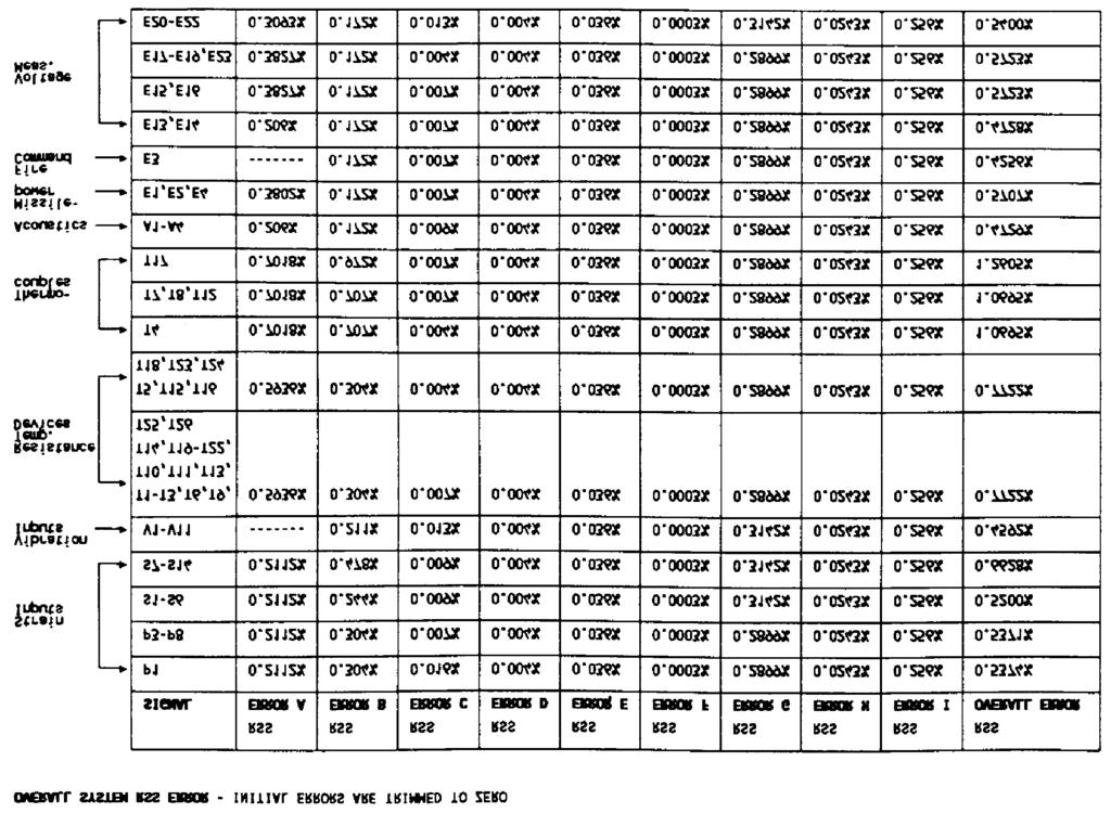
2 MIL-STD-1553 DATA BUS/PCM MULTIPLEXER SYSTEM Erle W. Malone Boeing Aerospace Seattle, WA Phillip Breedlove Loral Conic San Diego, CA ABSTRACT A telemetry system which integrates MIL-STD-1553 bus data, dual-simplex bus data, vehicle performance data, and environmental sensor data multiplexing involves many interfacing constraints. The engineering design considerations and hardware constraints required to implement this system are presented in this paper. INTRODUCTION This system interfaces with a 1553 data bus in a bus monitor capacity and with an operational payload data bus. At the same time, it multiplexes performance and environmental data from a test vehicle operating in a flight regime. (Figure 1 is a block diagram of the system.) The 1553 bus interface design requires that the system perform as a monitor and as a dummy remote terminal which does not respond with a status message. The processing design incorporates these constraints by modifying protocol tracking and message gap requirements. The system integrates the bus and sampled data into a secure 2.0 MBPS serial data stream conditioned for transmission. The elements of the system are 1) 1553 Bus Data Processor, 2) Dual-Simplex Operational Payload Simulator, 3) Analog/Digital Signal Multiplexer, 4) Analog/Digital Signal Conditioner, 5) Format and Timing Unit, and 6) A Secure Data Support Unit. The entire system is packaged in a volume of less than 700 cubic inches BUS DATA PROCESSING SECTION The bus data processing section consists of a bus monitor, microprocessor, and buffer as shown in Figure 2. It monitors all 1553 bus data and converts the 20-bit words to a 24-bit word as defined in Chapter 8 of IRIG The formatting differs, however, because of supercommutation requirements. The 24-bit words,
3 are made up of the 16-bit data words pre-pended with an 8-bit ID word, including a parity bit as shown in Table 1. These converted 24-bit words are inserted into the telemetry format at a 41 KWPS rate. This is adequate for a 1553 bus operating at a maximum rate of 46 KWPS (92% efficiency). The processing section can buffer a maximum word rate for 30 milliseconds without overflow. The data latency is a variable ranging from 76 microseconds to 4.9 milliseconds. (This is the time from the entry of a 1553 word into the processing section until it is output to a transmitter.) The actual time is dependent upon the timing between the buffer and the PCM format position. Certain bit data words, a maximum of 32, are selected by the Quick Look (QL) module. The data words are transferred to the QL port which interfaces with the format and timing sections. The incoming data rate can be as high as 350 WPS. The data will be processed by the QL buffer and inserted into the format at WPS, the subcom rate. If there is no change in the data between minor frames, the last data word is inserted. Thus, data of single-occurrence events will be transmitted continuously. Data latency for these words is much greater because of the longer time that the data must be buffered until it is inserted into the frame format. Data latency varies from 73 microseconds to 32.7 milliseconds. As can be seen in Table 1, there are filler words (16 bits of an alternating 1/0 pattern) and error ID s. The filler words aid in keeping an adequate number of bit transitions for maintaining synchronization of a data processing decommutator. This is necessary when the bus is down or if bus protocol is being continuously distorted. The error word ID is attached to the data word, without passing judgement on the validity of the data, only when an error is detected. Errors may include the occurrence of improper parity, invalid sync, incorrect sync, Manchester error, or incorrect bit count. The data word as received is combined with the error ID to form a 24-bit word that can be used during post-test bus diagnostics at a data processing facility. ANALOG MULTIPLEXER Test vehicle performance and environmental data is monitored by 77 analog/discrete inputs. These are specifically tailored to the input characteristics and spectral content of the data. Inputs consist of single-ended and differential data extracted from transducers such as strain gages, thermocouples, resistance temperature devices, vibration sensors, and acoustic sensors. Constant current and highly-stable, low-drift voltage sources provide excitation for the various
4 transducers. In addition, various system voltages are measured as single ended or discrete inputs and switch closures are output as digital words. A typical analog input path is depicted in Figure 3A. Input conditioning circuits are utilized to normalize the various types of inputs. This ensures that only unipolar or symmetrical bipolar inputs of less than 2.5 Volts peak-to-peak are present at the input of the instrumentation amplifier. This voltage level allows the programmable gain amplifier (PGA) to be preset to a nominal gain of 2 in case signal attenuation is required. It also satisfies input requirements for the 0-5 Volt sample/hold amplifier and A/D converter. The front-end instrumentation amplifier is used to provide accurate, stable gain for low-level inputs of either single-ended or differential types. It also drives the pre-sample anti-aliasing filters. Each input channel has separate gain and filter circuits. The anti-aliasing filters are Butterworth types with 1, 2 or 4 poles, depending upon the spectral content and input level of each signal. The 2- and 4-pole filter roll-offs (3 db) are set for one-fifth the sample rate. After pre-sample filtering is complete, the seven channels on each signal conditioning card are multiplexed into a single PGA. The PGA gain is controlled by an externally-programmable device (EPROM) and has a dynamic range of 1 to 32 steps with a nominal gain of 2 preset. This allows for a maximum programmable amplification of 16 or attenuation of 0.5. One of the most crucial elements of the entire analog design process was to satisfy system bit rate and accuracy requirements for 77 channels while maintaining design simplicity. With a system bit rate of 2 MBPS, only 4.0 microseconds per 8-bit word was available for the A/D conversion process. The precision A/D converter used for this application requires a minimum of 1.2 microsecond hold time when short cycled from 12 bits to 8 bits. Therefore, 3 bits (1.5 microseconds) was allocated for the hold time. This left 2.5 microseconds (5 bits) for settling and sample time. Settling time requirements were satisfied by multiplexing the analog signal as shown in Figure 4. This design-simplifying feature constrains the format so that each of the 11 analog signal conditioning boards can only be addressed every fourth word. The analog multiplexing design resulted in complete settling at the output of the PGA prior to being switched onto the analog bus shared by the signal conditioning boards. The bus capacitance was large due to the additive effect of 1) board enable switches on each signal conditioning card, and 2) the analog bus capacitance. This dictated the following design considerations:
5 A) Use of a current driver for each signal conditioner output B) Short the capacitance-developed bus potentials to ground during the A/D hold times These two design considerations insure that there is adequate drive capability and that each analog measurement is subjected to equivalent initial conditions resulting in minimal signal crosstalk. Finally, to satisfy the gain programming requirements for both unipolar and bipolar inputs to the unipolar A/D converter, a two-value programmable offset is applied to the analog measurements prior to the A/D conversion. The offsets are programmed to zero for unipolar inputs and to 50% full scale for bipolar inputs. This results in a uniform A/D input signal level of 0-5 Volts for all analog signals. Note that due to the symmetrical characteristics of the bipolar signals, only 50% full-scale offsets are required. (Non-symmetric data signals would require offsets tailored to input signal characteristics.) This simplistic design thus achieves the required accuracy as shown by the calculations in Figure 3B. OPERATIONAL PAYLOAD SIMULATOR The simulator dual-simplex bus uses optical couplers to interface with an avionics computer. These couplers provide the necessary isolation required by the avionics system. The simulator state machine receives and recognizes 20 valid command messages and responds with 7 unique predetermined messages. The byte format of each message is: a start bit, 8 data bits, 1 parity bit, and a stop bit transmitted in a serial data format, LSB first. When valid command messages are recognized, associated data and CRC (circular redundancy check) words of the message are ignored. The recognized sync word is then used to initiate sending a canned response message, and sets a bit in a digital word, indicating that the command has been received and recognized. Each message includes a status word, data words, a two-word CRC, and a synchronization word, occurring in the following order: STATUS WORD, DATA WORD,..,DATA WORD, CRC1 WORD, CRC2 WORD, SYNC The two canned CRC words in the 7 response messages are derived using Modulo 2 arithmetic from the first 6 least significant bits of the status and data words of the message. The sync word is not used in the derivation. The CRC polynomial for the derivation is X + X, + X + X + X + 1. The generated CRC
6 word 1 contains the 6 least significant derived CRC bits appended with a binary 01. CRC word 2 contains the derived 6 most significant bits, also appended with a binary 01. The simulator also accepts a timing discrete (minimum pulse duration of 3 milliseconds) from the avionics computer through an optically-isolated interface. The coupled signal interfaces with an analog channel sampled at 1000 times per second. ACKNOWLEDGMENTS The system described in this paper is the result of cooperation between Boeing Aerospace and Loral Conic personnel. The authors wish to thank the participants from both organizations for their enthusiasm and dedication during system development and the preparation of this paper. TABLE BIT WORD STRUCTURE ID BITS ± DATA BITS WORD DESCRIPTION P COMMAND A P STATUS A P DATA A P ERROR A P FILLER P COMMAND 8 P STATUS B P DATA B P ERROR B A = Primary channel of a dual redundant bus B = Secondary channel of a dual redundant bus P = Parity Bit (odd parity) TABLE II. MULTIPLEXER FORMAT A B C D E F G H I J K L M N -WI-- -W2-- -W3-- -W4-- A B C D E F G H I J K -W5-- -W6-- -W7-- -W8-- -W9-- A B C D E F G H I J K L M N -W10- -W11- -W12- -W13- A B C D E F G H I J K -W14- -W15- -W16- -W17- -W18- A B C D E F G H I J K L M N -W19- -W20- -W21- -W22- A B C D E F G H I J K -W23- -W24- -W25- -W26- -W27- A B C D E F G H I J K L M N -W28- -W29- -W30- -W31- A B C D E F G H I J K -W32- -W33- -W34- -W35- -W36- A B C D E F G H I J K L M N -W37- -W38- -W39- -W40- A B C D E F G H I J K -W41- P U U U U U Q Q S S S I 8 BITS/WORD 250 WORDS/FRAME 1000 FRAMES/SEC 2.0 MBPS 32 FRAMES/MAJOR FRAME 14 SUPERCOM WORDS
7
8 Figure 1
9 Figure 3A.
10 Figure 3B.

11
CHAPTER 8 DIGITAL DATA BUS ACQUISITION FORMATTING STANDARD TABLE OF CONTENTS. Paragraph Subject Page
 CHAPTER 8 DIGITAL BUS ACQUISITION FORMATTING STANDARD TABLE OF CONTENTS Paragraph Subject Page 8.1 General... 8-1 8.2 Word Structure... 8-1 8.3 Time Words... 8-3 8.4 Composite Output... 8-4 8.5 Single
ACCURACY JUNGLE TRUE OR FALSE?
 1 ACCURACY JUNGLE TRUE OR FALSE? Steve Pellarin and Albert Berdugo Teletronics Technology Corporation Newtown, PA USA Abstract Today s advanced vehicles demand high performance data acquisition systems
DIGITAL FILTERING OF MULTIPLE ANALOG CHANNELS
 DIGITAL FILTERING OF MULTIPLE ANALOG CHANNELS Item Type text; Proceedings Authors Hicks, William T. Publisher International Foundation for Telemetering Journal International Telemetering Conference Proceedings
ROM/UDF CPU I/O I/O I/O RAM
 DATA BUSSES INTRODUCTION The avionics systems on aircraft frequently contain general purpose computer components which perform certain processing functions, then relay this information to other systems.
A/D Converter An electronic circuit that transforms an analog signal into a digital form that can be used by a computer or other digital circuits.
 Digital Audio Terms A/D Converter An electronic circuit that transforms an analog signal into a digital form that can be used by a computer or other digital circuits. Aliasing An undesirable effect that
Design Implementation Description for the Digital Frequency Oscillator
 Appendix A Design Implementation Description for the Frequency Oscillator A.1 Input Front End The input data front end accepts either analog single ended or differential inputs (figure A-1). The input
A DSP IMPLEMENTED DIGITAL FM MULTIPLEXING SYSTEM
 A DSP IMPLEMENTED DIGITAL FM MULTIPLEXING SYSTEM Item Type text; Proceedings Authors Rosenthal, Glenn K. Publisher International Foundation for Telemetering Journal International Telemetering Conference
Data acquisition and instrumentation. Data acquisition
 Data acquisition and instrumentation START Lecture Sam Sadeghi Data acquisition 1 Humanistic Intelligence Body as a transducer,, data acquisition and signal processing machine Analysis of physiological
1 UAT Test Procedure and Report
 1 UAT Test Procedure and Report These tests are performed to ensure that the UAT Transmitter will comply with the equipment performance tests during and subsequent to all normal standard operating conditions
DS1807 Addressable Dual Audio Taper Potentiometer
 Addressable Dual Audio Taper Potentiometer www.dalsemi.com FEATURES Operates from 3V or 5V Power Supplies Ultra-low power consumption Two digitally controlled, 65-position potentiometers Logarithmic resistor
TRANSMISSION OF RADIOMETER DATA FROM THE SYNCHRONOUS METEOROLOGICAL SATELLITE
 TRANSMISSION OF RADIOMETER DATA FROM THE SYNCHRONOUS METEOROLOGICAL SATELLITE Item Type text; Proceedings Authors Davies, Richard S. Publisher International Foundation for Telemetering Journal International
INTEGRATED CIRCUITS. AN109 Microprocessor-compatible DACs Dec
 INTEGRATED CIRCUITS 1988 Dec DAC products are designed to convert a digital code to an analog signal. Since a common source of digital signals is the data bus of a microprocessor, DAC circuits that are
Theoretical 1 Bit A/D Converter
 Acquisition 16.1 Chapter 4 - Acquisition D/A converter (or DAC): Digital to Analog converters are used to map a finite number of values onto a physical output range (usually a ) A/D converter (or ADC):
Small EHF/SHF Airborne SATCOM Terminal
 Small EHF/SHF Airborne SATCOM Terminal Item Type text; Proceedings Authors Johnson, Allen L.; Joyner, Thomas E. Publisher International Foundation for Telemetering Journal International Telemetering Conference
ADVANCED DISTRIBUTED WIDEBAND DATA ACQUISITION SYSTEM
 ADVANCED DISTRIBUTED WIDEBAND DATA ACQUISITION SYSTEM Albert Berdugo Vice President of Advanced Product Development Teletronics Technology Corporation Newtown, PA USA ABSTRACT Wideband data acquisition
8-Bit A/D Converter AD673 REV. A FUNCTIONAL BLOCK DIAGRAM
 a FEATURES Complete 8-Bit A/D Converter with Reference, Clock and Comparator 30 s Maximum Conversion Time Full 8- or 16-Bit Microprocessor Bus Interface Unipolar and Bipolar Inputs No Missing Codes Over
Computer Networks MCQS MCQs Questions
 http://itbookshub.com/ Computer Networks MCQS MCQs Multiple Choice Questions Computer Networks MCQS Question 1: In OSI network architecture, the dialogue control and token management are responsibility
MECE 3320 Measurements & Instrumentation. Data Acquisition
 MECE 3320 Measurements & Instrumentation Data Acquisition Dr. Isaac Choutapalli Department of Mechanical Engineering University of Texas Pan American Sampling Concepts 1 f s t Sampling Rate f s 2 f m or
EDS-400A COMPACT RECORDER. New KYOWA ELECTRONIC INSTRUMENTS CO., LTD.
 KYOWA ELECTRONIC INSTRUMENTS CO., LTD. COMPACT RECORDER EDS-400A Compact Dynamic Strain Recorder Entering the scene in advanced measurement of strain, vibration, pressure, load, etc. New www.kyowa-ei.co.jp
ni.com Sensor Measurement Fundamentals Series
 Sensor Measurement Fundamentals Series Introduction to Data Acquisition Basics and Terminology Litkei Márton District Sales Manager National Instruments What Is Data Acquisition (DAQ)? 3 Why Measure? Engineers
Physical Layer, Part 2. Analog and Digital Transmission
 CS 656 Analog/Digital, Page 1 Physical Layer, Part 2 Analog and Digital Transmission These slides are created by Dr. Yih Huang of George Mason University. Students registered in Dr. Huang s courses at
Department of Electronics & Telecommunication Engg. LAB MANUAL. B.Tech V Semester [ ] (Branch: ETE)
![Department of Electronics & Telecommunication Engg. LAB MANUAL. B.Tech V Semester [ ] (Branch: ETE)](/thumbs/86/93078052.jpg "Department of Electronics & Telecommunication Engg. LAB MANUAL. B.Tech V Semester [ ] (Branch: ETE)") Department of Electronics & Telecommunication Engg. LAB MANUAL SUBJECT:-DIGITAL COMMUNICATION SYSTEM [BTEC-501] B.Tech V Semester [2013-14] (Branch: ETE) KCT COLLEGE OF ENGG & TECH., FATEHGARH PUNJAB TECHNICAL
Department of Electronics & Telecommunication Engg. LAB MANUAL SUBJECT:-DIGITAL COMMUNICATION SYSTEM [BTEC-501] B.Tech V Semester [2013-14] (Branch: ETE) KCT COLLEGE OF ENGG & TECH., FATEHGARH PUNJAB TECHNICAL
Communications I (ELCN 306)
") Communications I (ELCN 306) c Samy S. Soliman Electronics and Electrical Communications Engineering Department Cairo University, Egypt Email: samy.soliman@cu.edu.eg Website: http://scholar.cu.edu.eg/samysoliman
Communications I (ELCN 306) c Samy S. Soliman Electronics and Electrical Communications Engineering Department Cairo University, Egypt Email: samy.soliman@cu.edu.eg Website: http://scholar.cu.edu.eg/samysoliman
SMARTALPHA RF TRANSCEIVER
 SMARTALPHA RF TRANSCEIVER Intelligent RF Modem Module RF Data Rates to 19200bps Up to 300 metres Range Programmable to 433, 868, or 915MHz Selectable Narrowband RF Channels Crystal Controlled RF Design
6. has units of bits/second. a. Throughput b. Propagation speed c. Propagation time d. (b)or(c)
or(c)") King Saud University College of Computer and Information Sciences Information Technology Department First Semester 1436/1437 IT224: Networks 1 Sheet# 10 (chapter 3-4-5) Multiple-Choice Questions 1. Before
King Saud University College of Computer and Information Sciences Information Technology Department First Semester 1436/1437 IT224: Networks 1 Sheet# 10 (chapter 3-4-5) Multiple-Choice Questions 1. Before
ELG3336 Design of Mechatronics System
 ELG3336 Design of Mechatronics System Elements of a Data Acquisition System 2 Analog Signal Data Acquisition Hardware Your Signal Data Acquisition DAQ Device System Computer Cable Terminal Block Data Acquisition
F2-04AD-1, F2-04AD-1L 4-Channel Analog Current Input
 F2-4AD-1, F2-4AD-1L 4-Channel Analog Current 2 InThisChapter... Module Specifications Setting the Module Jumpers Connecting the Field Wiring Module Operation Writing the Control Program 2-2 Module Specifications
This Errata Sheet contains corrections or changes made after the publication of this manual.
 Errata Sheet This Errata Sheet contains corrections or changes made after the publication of this manual. Product Family: DL4 Date: September 12, 218 Manual Number D4-ANLG-M Revision and Date th Ed., Rev.
THE GPS SATELLITE AND PAYLOAD
 THE GPS SATELLITE AND PAYLOAD Andrew Codik and Robert A. Gronlund Rockwell International Corporation Satellite Systems Division 12214 Lakewood Boulevard Downey, California, USA 90241 ABSTRACT The NAVSTAR/Global
Spacecraft to Science Instrument Data Interface Control Document. Dwg. No
 Rev. ECO Description Checked Approval Date 01 Initial Release for S/C negotiation RFGoeke 4 Oct.02 Spacecraft to Science Instrument Data Interface Control Document Dwg. No. 43-03001 Revision 01 4 October
DS1802 Dual Audio Taper Potentiometer With Pushbutton Control
 www.dalsemi.com FEATURES Ultra-low power consumption Operates from 3V or 5V supplies Two digitally controlled, 65-position potentiometers including mute Logarithmic resistive characteristics (1 db per
AN OPERATIONAL TEST INSTRUMENT FOR PCM BIT SYNCHRONIZERS/SIGNAL CONDITIONERS
 AN OPERATIONAL TEST INSTRUMENT FOR PCM BIT SYNCHRONIZERS/SIGNAL CONDITIONERS R. G. CUMINGS and R. A. DAVIES DEFENSE ELECTRONICS, INC. Summary The application for a device which will effectively test a
EX FEATURES. Stand-alone 48-channel unit with built-in Ethernet controller. Built-in bridge completion and Excitation
 data sheet EX1629-001 High-performance Remote Strain Gage Measurement Unit FEATURES Stand-alone 48-channel unit with built-in Ethernet controller Built-in bridge completion and Excitation 24-bit A/D per
Microprocessor-Compatible 12-Bit D/A Converter AD667*
 a FEATURES Complete 12-Bit D/A Function Double-Buffered Latch On Chip Output Amplifier High Stability Buried Zener Reference Single Chip Construction Monotonicity Guaranteed Over Temperature Linearity
Basic Communications Theory Chapter 2
 TEMPEST Engineering and Hardware Design Dr. Bruce C. Gabrielson, NCE 1998 Basic Communications Theory Chapter 2 Communicating Information Communications occurs when information is transmitted or sent between
Tracking, Telemetry and Command
 Tracking, Telemetry and Command Jyh-Ching Juang ( 莊智清 ) Department of Electrical Engineering National Cheng Kung University juang@mail.ncku.edu.tw April, 2006 1 Purpose Given that the students have acquired
DATA SHEET. TDA8415 TV and VTR stereo/dual sound processor with integrated filters and I 2 C-bus control INTEGRATED CIRCUITS
 INTEGRATED CIRCUITS DATA SHEET TV and VTR stereo/dual sound processor with integrated filters and I 2 C-bus control File under Integrated Circuits, IC02 May 1989 with integrated filters and I 2 C-bus control
Tel: Fax:
 B Tel: 78.39.4700 Fax: 78.46.33 SPECIFICATIONS (T A = +5 C, V+ = +5 V, V = V or 5 V, all voltages measured with respect to digital common, unless otherwise noted) AD57J AD57K AD57S Model Min Typ Max Min
LDTEDS: A Method for Long Distance Communication to Smart Transducers with TEDS
 LDTEDS: A Method for Long Distance Communication to Smart Transducers with TEDS Stephen H. Finney Douglas R. Firth Precision Filters, Inc. Ithaca, New York (607) 277-3550 The IEEE 1451.4 standard defines
Chapter 2 Analog-to-Digital Conversion...
 Chapter... 5 This chapter examines general considerations for analog-to-digital converter (ADC) measurements. Discussed are the four basic ADC types, providing a general description of each while comparing
Design of Xilinx Based Telemetry System Using Verilog
 Design of Xilinx Based Telemetry System Using Verilog N. P. Lavanya Kumari 1, A. Sarvani 2, K. S. S. Soujanya Kumari 3, L. Y. Swathi 4, M. Purnachandra Rao 5 1 Assistant.Professor (C), Department of Systems
745 Transformer Protection System Communications Guide
 Digital Energy Multilin 745 Transformer Protection System Communications Guide 745 revision: 5.20 GE publication code: GEK-106636E GE Multilin part number: 1601-0162-A6 Copyright 2010 GE Multilin GE Multilin
Superseded by a more recent version INTERNATIONAL TELECOMMUNICATION UNION
 INTERNATIONAL TELECOMMUNICATION UNION ITU-T V.24 TELECOMMUNICATION STANDARDIZATION SECTOR OF ITU (10/96) SERIES V: DATA COMMUNICATION OVER THE TELEPHONE NETWORK Interfaces and voiceband modems List of
Application Note 160 Using the DS1808 in Audio Applications
 www.maxim-ic.com Application Note 160 Using the DS1808 in Audio Applications Introduction The DS1808 Dual Log Audio Potentiometer was designed to provide superior audio performance in applications that
8248AU. 4-Ch Isolated Amplifier with Optional Bridge Conditioning FEATURES TYPICAL APPLICATIONS
 8248AU The 8248AU is a single-width, 4-Ch Isolated Amplifier with Optional Bridge Conditioning 6U, CompactPCI/PXI module with 4 channels of Isolated Signal Conditioning feeding two buffered outputs. This
This Errata Sheet contains corrections or changes made after the publication of this manual.
 Errata Sheet This Errata Sheet contains corrections or changes made after the publication of this manual. Product Family: DL35 Manual Number D3-ANLG-M Revision and Date 3rd Edition, February 23 Date: September
Analog I/O. ECE 153B Sensor & Peripheral Interface Design Winter 2016
 Analog I/O ECE 153B Sensor & Peripheral Interface Design Introduction Anytime we need to monitor or control analog signals with a digital system, we require analogto-digital (ADC) and digital-to-analog
Aeroflex-Plainview. MIL-STD-1553 Glossary
 A Aeroflex-Plainview MIL-STD-1553 Glossary 1553 Military standard that establishes requirements for digital, command/response timedmision multiplexing techniques. In this handbook, 1553 is used as a generic
Linear Technology Chronicle
 Linear Technology Chronicle High Performance Analog Solutions from Linear Technology Vol. 13 No. 5 Industrial Process Control LT1790-2.5 LTC2054 REMOTE THERMOCOUPLE CH0 CH1 CH7 CH8 CH15 COM REF 16-CHANNEL
Transient Data Acquisition Solutions
 Transient Data Acquisition Solutions Faster Analysis Times Reducing Data Storage Lower Channel Bandwidth Transient Data Acquisition methodologies can overcome the shortcomings of conventional data logging
BusWorks 900EN Series Modbus TCP/IP 10/100M Industrial Ethernet I/O Modules
 BusWorks 900EN Series Modbus TCP/IP 10/100M Industrial Ethernet I/O Modules Six Differential Current Inputs Six Differential Voltage Inputs USER S MANUAL ACROMAG INCORPORATED Tel: (248) 295-0880 30765
EECS 122: Introduction to Computer Networks Encoding and Framing. Questions
 EECS 122: Introduction to Computer Networks Encoding and Framing Computer Science Division Department of Electrical Engineering and Computer Sciences University of California, Berkeley Berkeley, CA 94720-1776
VersaPoint I/O Module
 GFK-2012A March 2010 Module provides two-input channels for measuring signals from standard thermocouples. It supports thirteen different thermocouples types. In addition, it accepts linear voltage inputs
EECE494: Computer Bus and SoC Interfacing. Serial Communication: RS-232. Dr. Charles Kim Electrical and Computer Engineering Howard University
 EECE494: Computer Bus and SoC Interfacing Serial Communication: RS-232 Dr. Charles Kim Electrical and Computer Engineering Howard University Spring 2014 1 Many types of wires/pins in the communication
Advances in Antenna Measurement Instrumentation and Systems
 Advances in Antenna Measurement Instrumentation and Systems Steven R. Nichols, Roger Dygert, David Wayne MI Technologies Suwanee, Georgia, USA Abstract Since the early days of antenna pattern recorders,
Features EX1629. High-performance Remote Strain Gage Measurement Unit. Overview. 48 programmable channels in a single unit
 Overview The VXI Technology EX1629 Remote Strain Gage simplifies stress and fatigue testing of large mechanical structures such as airframes and launch vehicles. Ethernet control allows for remote operation
Refer to Sub-section. Input range * * 9 ranges. Related processing * * Square root extraction. Measurement * * 3 types of scaling scaling
 X Preface The TSX AEM 811 analog input module offers a number of functions that are identical to those of the TSX AEM 411 module but with some operating variations. The table below lists the main functions
Module 1: Introduction to Experimental Techniques Lecture 2: Sources of error. The Lecture Contains: Sources of Error in Measurement
 The Lecture Contains: Sources of Error in Measurement Signal-To-Noise Ratio Analog-to-Digital Conversion of Measurement Data A/D Conversion Digitalization Errors due to A/D Conversion file:///g /optical_measurement/lecture2/2_1.htm[5/7/2012
Silicon-Gate Switching Functions Optimize Data Acquisition Front Ends
 Silicon-Gate Switching Functions Optimize Data Acquisition Front Ends AN03 The trend in data acquisition is moving toward ever-increasing accuracy. Twelve-bit resolution is now the norm, and sixteen bits
SAPLING WIRELESS SYSTEM
 SAPLING WIRELESS SYSTEM Sapling Wireless System DESCRIPTION A Wireless Clock System starts with a master clock with a transmitter. The master clock s transmitter transmits the time data to the secondary
EVDP610 IXDP610 Digital PWM Controller IC Evaluation Board
 IXDP610 Digital PWM Controller IC Evaluation Board General Description The IXDP610 Digital Pulse Width Modulator (DPWM) is a programmable CMOS LSI device, which accepts digital pulse width data from a
QUAD-CHANNEL CONDITIONER BALANCED CURRENT EXCITATION ±10 V Common Mode; 255 or 510 Cutoff Frequencies
 28454 QUAD-CHANNEL CONDITIONER BALANCED CURRENT EXCITATION ±10 V Common Mode; 255 or 510 Cutoff Frequencies SYSTEM 28000 FEATURES Graphical User Interface (GUI) for system control Intelligent gain and
Part IV: Glossary of Terms
 Issue 9 November 2004 Spectrum Management and Telecommunications Policy Compliance Specification for Terminal Equipment, Terminal Systems, Network Protection Devices, Connection Arrangements and Hearing
SCI ISO-K CCD PCI CAN
 DCX Networks SCI (Serial Communication Interface): The system uses two wires; one to transmit and one to receive. ISO-K is the adaptation of the 9141 standards allowing two-way communication on a single
PULSE CODE MODULATION TELEMETRY Properties of Various Binary Modulation Types
 PULSE CODE MODULATION TELEMETRY Properties of Various Binary Modulation Types Eugene L. Law Telemetry Engineer Code 1171 Pacific Missile Test Center Point Mugu, CA 93042 ABSTRACT This paper discusses the
LC 2 MOS 8-Channel, 12-Bit Serial, Data Acquisition System AD7890
 a LC 2 MOS 8-Channel, 12-Bit Serial, Data Acquisition System AD7890 FEATURES Fast 12-Bit ADC with 5.9 s Conversion Time Eight Single-Ended Analog Input Channels Selection of Input Ranges: 10 V for AD7890-10
Downloaded from 1
 VII SEMESTER FINAL EXAMINATION-2004 Attempt ALL questions. Q. [1] How does Digital communication System differ from Analog systems? Draw functional block diagram of DCS and explain the significance of
16-Bit, Low-Power, 2-Channel, Sigma-Delta ADC MX7705
 General Description The MX7705 low-power, 2-channel, serial-output analog-to-digital converter (ADC) includes a sigma-delta modulator with a digital filter to achieve 16-bit resolution with no missing
A Compatible Double Sideband/Single Sideband/Constant Bandwidth FM Telemetry System for Wideband Data
 A Compatible Double Sideband/Single Sideband/Constant Bandwidth FM Telemetry System for Wideband Data Item Type text; Proceedings Authors Frost, W. O.; Emens, F. H.; Williams, R. Publisher International
SGLS Test Set. Model 630. General Description
 Features 3 Operational Modes GL Ternary erial data GL Command Processor Test 4 Command Rates kbps & 2 kbps (td) Other Rates (optional) Independent Transmit and Receive ix Pseudorandom Data Patterns 2 7,
Applications. Operating Modes. Description. Part Number Description Package. Many to one. One to one Broadcast One to many
 RXQ2 - XXX GFSK MULTICHANNEL RADIO TRANSCEIVER Intelligent modem Transceiver Data Rates to 100 kbps Selectable Narrowband Channels Crystal controlled design Supply Voltage 3.3V Serial Data Interface with
Time division multiplexing The block diagram for TDM is illustrated as shown in the figure
 CHAPTER 2 Syllabus: 1) Pulse amplitude modulation 2) TDM 3) Wave form coding techniques 4) PCM 5) Quantization noise and SNR 6) Robust quantization Pulse amplitude modulation In pulse amplitude modulation,
Lecture 3: Modulation & Clock Recovery. CSE 123: Computer Networks Alex C. Snoeren
 Lecture 3: Modulation & Clock Recovery CSE 123: Computer Networks Alex C. Snoeren Lecture 3 Overview Signaling constraints Shannon s Law Nyquist Limit Encoding schemes Clock recovery Manchester, NRZ, NRZI,
Channel Concepts CS 571 Fall Kenneth L. Calvert
 Channel Concepts CS 571 Fall 2006 2006 Kenneth L. Calvert What is a Channel? Channel: a means of transmitting information A means of communication or expression Webster s NCD Aside: What is information...?
Wireless Sensor System for Airborne Applications
 Wireless Sensor System for Airborne Applications Steve Pellarin and Hy Grossman Teletronics Technology Corporation Steven Musteric 46 th Test Systems Squadron Eglin Air Force Base, FL Abstract Adding an
CS601 Data Communication Solved Objective For Midterm Exam Preparation
 CS601 Data Communication Solved Objective For Midterm Exam Preparation Question No: 1 Effective network mean that the network has fast delivery, timeliness and high bandwidth duplex transmission accurate
F2-04AD-2, F2-04AD-2L 4-Channel Analog Voltage Input
 F2-04AD-2, F2-04AD-2L 4-Channel Analog Voltage 2 F2-04AD-2, F2-04AD-2L 4-Channel Analog Voltage Module Specifications The F2-04AD-2 (24 VDC input power model) and F2-04AD-2L (12 VDC input power model)
CHAPTER 3 Syllabus (2006 scheme syllabus) Differential pulse code modulation DPCM transmitter
 Differential pulse code modulation DPCM transmitter") CHAPTER 3 Syllabus 1) DPCM 2) DM 3) Base band shaping for data tranmission 4) Discrete PAM signals 5) Power spectra of discrete PAM signal. 6) Applications (2006 scheme syllabus) Differential pulse code
CHAPTER 3 Syllabus 1) DPCM 2) DM 3) Base band shaping for data tranmission 4) Discrete PAM signals 5) Power spectra of discrete PAM signal. 6) Applications (2006 scheme syllabus) Differential pulse code
A-D and D-A Converters
 Chapter 5 A-D and D-A Converters (No mathematical derivations) 04 Hours 08 Marks When digital devices are to be interfaced with analog devices (or vice a versa), Digital to Analog converter and Analog
Chapter 2 TELEMETRY SYETEMS
 Chapter 2 TELEMETRY SYETEMS Dr. H.K. VERMA Distinguished Professor Department of Electrical and Electronics Engineering School of Engineering and Technology SHARDA UNIVERSITY Greater Noida, India website:
Encoding and Framing
 Encoding and Framing EECS 489 Computer Networks http://www.eecs.umich.edu/~zmao/eecs489 Z. Morley Mao Tuesday Nov 2, 2004 Acknowledgement: Some slides taken from Kurose&Ross and Katz&Stoica 1 Questions
Digital Potentiometers Selection Guides Don t Tell the Whole Story
 Digital Potentiometers Page - 1 - of 10 Digital Potentiometers Selection Guides Don t Tell the Whole Story by Herman Neufeld, Business Manager, Europe Maxim Integrated Products Inc., Munich, Germany Since
FYS3240 PC-based instrumentation and microcontrollers. Signal sampling. Spring 2017 Lecture #5
 FYS3240 PC-based instrumentation and microcontrollers Signal sampling Spring 2017 Lecture #5 Bekkeng, 30.01.2017 Content Aliasing Sampling Analog to Digital Conversion (ADC) Filtering Oversampling Triggering
Technical Brief FAQ (FREQUENCLY ASKED QUESTIONS) For further information, please contact Crystal Semiconductor at (512) or 1 (800)
 For further information, please contact Crystal Semiconductor at (512) or 1 (800)") Technical Brief FAQ (FREQUENCLY ASKED QUESTIONS) 1) Do you have a four channel part? Not at this time, but we have plans to do a multichannel product Q4 97. We also have 4 digital output lines which can
Technical Brief FAQ (FREQUENCLY ASKED QUESTIONS) 1) Do you have a four channel part? Not at this time, but we have plans to do a multichannel product Q4 97. We also have 4 digital output lines which can
Appendix A. Datum Systems PSM-2100/512 Satellite Modem. Technical Specification
 Appendix A Datum Systems PSM-2100/512 Satellite Modem Technical Specification PSM-2100 and PSM-512 VSAT / SCPC - Modem Specification Revision History Rev 1.0 6-15-97 Preliminary Release. Rev 1.1 10-10-97
Encoding and Framing. Questions. Signals: Analog vs. Digital. Signals: Periodic vs. Aperiodic. Attenuation. Data vs. Signal
 Questions Encoding and Framing Why are some links faster than others? What limits the amount of information we can send on a link? How can we increase the capacity of a link? EECS 489 Computer Networks
Interoperability of FM Composite Multiplex Signals in an IP Based STL
 Interoperability of FM Composite Multiplex Signals in an IP Based STL Featuring GatesAir s April 23, 2017 NAB Show 2017 Junius Kim Hardware Engineer Keyur Parikh Director, Intraplex Copyright 2017 GatesAir,
Chapter 4 Digital Transmission 4.1
 Chapter 4 Digital Transmission 4.1 Copyright The McGraw-Hill Companies, Inc. Permission required for reproduction or display. 4-1 DIGITAL-TO-DIGITAL CONVERSION In this section, we see how we can represent
GSM BASED PATIENT MONITORING SYSTEM
 GSM BASED PATIENT MONITORING SYSTEM ABSTRACT This project deals with the monitoring of the patient parameters such as humidity, temperature and heartbeat. Here we have designed a microcontroller based
Sigma-Delta ADCs. Benefits and Features. General Description. Applications. Functional Diagram
 EVALUATION KIT AVAILABLE MAX1415/MAX1416 General Description The MAX1415/MAX1416 low-power, 2-channel, serialoutput analog-to-digital converters (ADCs) use a sigmadelta modulator with a digital filter
Digital signal is denoted by discreet signal, which represents digital data.there are three types of line coding schemes available:
 Digital-to-Digital Conversion This section explains how to convert digital data into digital signals. It can be done in two ways, line coding and block coding. For all communications, line coding is necessary
Kongsberg Mesotech Ltd.
 Kongsberg Mesotech Ltd. Doc. No. : 974-00007904 Title : Digital Telemetry Notes elease : Version 1.4 Date : 2010-04-30 1. PUPOSE This document briefly describes the digital telemetry standards, formats
INTERNATIONAL TELECOMMUNICATION UNION DATA COMMUNICATION OVER THE TELEPHONE NETWORK
 INTERNATIONAL TELECOMMUNICATION UNION ITU-T V.24 TELECOMMUNICATION (03/93) STANDARDIZATION SECTOR OF ITU DATA COMMUNICATION OVER THE TELEPHONE NETWORK LIST OF DEFINITIONS FOR INTERCHANGE CIRCUITS BETWEEN
FC Series Signal Conditioners
 FC Series Signal Conditioners FC-33 DC Selectable Signal Conditioner with 3-way isolation Field configurable input and output ranges of 0-5V, 0-10 V, 0-20 ma and 4-20 ma with 1500 VDC isolation between
TELEMETRY RE-RADIATION SYSTEM
 TELEMETRY RE-RADIATION SYSTEM Paul Cook, Director, Missile Systems Teletronics Technology Corporation, Newtown, PA USA Louis Natale, F-22 Instrumentation Sr. Staff Engineer Lockheed Martin Aeronautics
APPENDIX C. Pulse Code Modulation Standards (Additional Information and Recommendations)
") APPENDIX C Pulse Code Modulation Standards (Additional Information and Recommendations) Acronyms C-iii 10 Bit Rate Versus Receiver Intermediate-Frequency Bandwidth C-5 20 Recommended PCM Synchronization
APPENDIX C Pulse Code Modulation Standards (Additional Information and Recommendations) Acronyms C-iii 10 Bit Rate Versus Receiver Intermediate-Frequency Bandwidth C-5 20 Recommended PCM Synchronization
EEE 309 Communication Theory
 EEE 309 Communication Theory Semester: January 2016 Dr. Md. Farhad Hossain Associate Professor Department of EEE, BUET Email: mfarhadhossain@eee.buet.ac.bd Office: ECE 331, ECE Building Part 05 Pulse Code
Functional Description
 Page 1 of 5 Submit Feedback Function Illustration The BMX AMI 0810 is a high density input analog module with 8 isolated channels. This module is used in conjunction with sensors or transmitters; it performs
Developer Techniques Sessions
 1 Developer Techniques Sessions Physical Measurements and Signal Processing Control Systems Logging and Networking 2 Abstract This session covers the technologies and configuration of a physical measurement
Telemetrie-Messtechnik Schnorrenberg
 Telemetrie-Messtechnik Schnorrenberg CT16-Wheel User manual TMS Telemetrie-Messtechnik Schnorrenberg Dipl.-Ing. Werner Schnorrenberg Habichtweg 30, D-51429 Bergisch Gladbach, Tel: 02204-9815-52, Fax: 02204-9815-53,