34XR Digital Multimeter. Users Manual
|
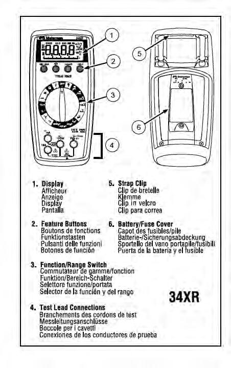
|
|
- Oscar Flynn
- 5 years ago
- Views:
Transcription
1
2
3 34XR Digital Multimeter Contents Safety Information... 2 Introduction... 3 Making Measurements... 3 Verify Instrument Operation... 3 Range Selection... 3 Correcting an Overload (o) Indication... 3 Measuring DC Voltage... See Figure Measuring AC Voltage (True rms)...see Figures -2- & Preparing for Current Measurements... 4 Measuring DC Current... See Figure Measuring AC Current (True rms)...see Figures -3- & Measuring Resistance... See Figure Measuring Continuity... See Figure Checking Diodes... See Figure Measuring Capacitance... See Figure Measuring Temperature...See Figure Measuring Frequency...See Figure Measuring Dutycycle...See Figure Additional Features... 6 Input Test Lead Warning... 6 True-rms Measurements... 6 MIN MAX Measurements... 6 Auto Power Off... 7 HOLD Measurements... 7 Backlight... 7 Product Maintenance... 7 Battery and Fuse Replacement...See Figure Repair... 8 WARRANTY... 9 Specifications... 9 Users Manual 1
4 Safety Information The 34XR Digital Multimeter is UL, cul, and EN certified for Installation Category III 600V and Category II 1000V. It is recommended for use with local level power distribution, appliances, portable equipment, etc, where only smaller transient overvoltages may occur, and not for primary supply lines, overhead lines and cable systems. Do not exceed the maximum overload limits per function (see specifications) nor the limits marked on the instrument itself. Never apply more than 1000V dc/750 V ac rms between the test lead and earth ground. Inspect the DMM, test leads and accessories before every use. Do not use any damaged part. Never ground yourself when taking measurements. Do not touch exposed circuit elements or test probe tips. Do not operate the instrument in an explosive atmosphere. Exercise extreme caution when: measuring voltage >20V // current >10mA // AC power line with inductive loads // AC power line during electrical storms // current, when the fuse blows in a circuit with open circuit voltage >1000 V // servicing CRT equipment. Always measure current in series with the load NEVER ACROSS a voltage source. Check fuse first. Never replace a fuse with one of a different rating. Remove test leads before opening the Battery Cover or case. Symbols Used in this Manual B Battery W Refer to the manual T Double insulated X Dangerous Voltage F Direct Current J Earth Ground B Alternating Current R Audible tone P I Complies with EU directives Fuse > Underwriters Laboratories, Inc 2
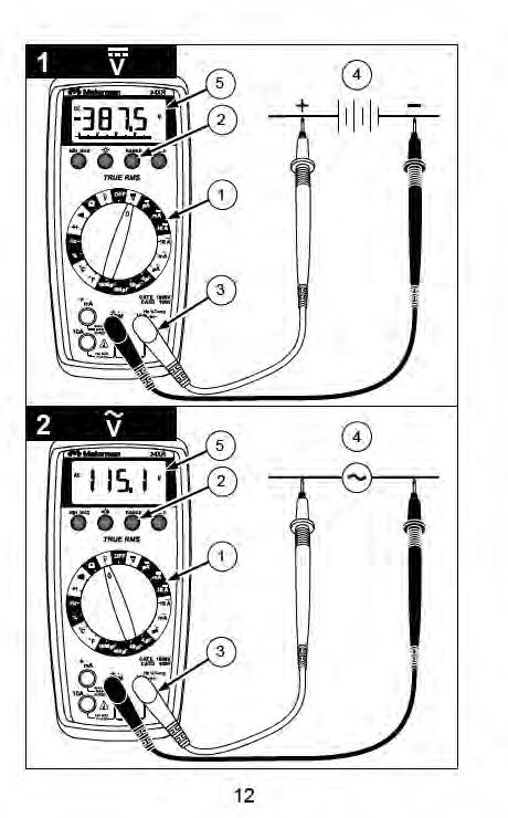
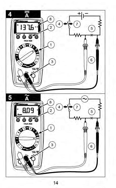
5 Introduction The 34XR is a True rms autoranging handheld digital multimeter for measuring or testing the following: DC and AC voltage Temperature DC and AC current Capacitance Resistance Diodes Frequency Continuity Dutycycle Additional features include: MIN MAX, HOLD, Backlight, and Range Lock Making Measurements Verify Instrument Operation Before attempting to make a measurement, verify that the instrument is operational and the battery is good. If the instrument is not operational, have it repaired before attempting to make a measurement. Range Selection In addition to autoranging the 34XR allows you to manually select and lock a range by pressing the RANGE button. RANGE appears on the display to indicate that manual ranging is active. Each subsequent press of the range button steps the meter to the next higher range. When the highest range is reached the next press returns the meter to the lowest range. To return to autoranging press and hold the RANGE button for 2 seconds. RANGE no longer shows on the display. Use autorange for all initial measurements. Then, when appropriate, use the RANGE button to select and lock a range. Warning To avoid electrical shock while manual ranging use the display annunciators to identify the actual range selected. Correcting an Overload (oor -o ) Indication W An o indication may appear on the display to indicate that an overload condition exists. For voltage and current measurements, an overload should be immediately corrected by selecting a higher range. If the highest range setting does not eliminate the overload, interrupt the measurement until the problem is identified and eliminated. The o indication is normal for some functions; for example, resistance, continuity, and diode test. Measuring DC Voltage See Figure Set the Function Switch to v. 2. If RANGE is displayed, press the RANGE button to enable autoranging. 3. Connect the Test Leads: Red to E, Black to COM 4. Connect the Test Probes to the circuit test points. 5. Read the display, and, if necessary, correct any overload (o) conditions. 3
6 Measuring AC Voltage (True rms) See Figures -2- & -3- See Additional Features to find out the advantages of true rms. 1. Set the Function Switch to V. 2. If RANGE is displayed, press the RANGE button to enable autoranging. 3. Connect the Test Leads: Red to E, Black to COM 4. Connect the Test Probes to the circuit test points 5. Read the display, and, if necessary, correct any overload (o) conditions. Preparing for Current Measurements Turn off circuit power before connecting the test probes. Allow the meter to cool between measurements if current measurements approach or exceeds 10 amps. A warning tone sounds if you connect a test lead to a current input before you select a current range. Open circuit voltage at the measurement point must not exceed 1000 V. Always measure current in series with the load. Never measure current across a voltage source. Measuring DC Current See Figure Set the Function Switch to a A function and range. 2. If RANGE is displayed, press the RANGE button to enable autoranging. 3. Connect the Test Leads: Red to µa ma or 10A, Black to COM 4. Turn off power to the circuit being measured. 5. Open the test circuit (X) to establish measurement points. 6. Connect the Test Probes in series with the load. 7. Turn on power to the circuit being measured. 8. Read the display, and, if necessary, correct any overload (o) conditions. Measuring AC Current (True rms) See Figures -3- & -5- See Additional Features to find out the advantages of true rms. 1. Set the Function Switch to a a function and range. 2. If RANGE is displayed, press the RANGE button to enable autoranging. 3. Connect the Test Leads: Red to µa ma or 10A, Black to COM 4. Turn off power to the circuit being measured. 5. Open the test circuit (X) to establish measurement points. 6. Connect the Test Probes in series with the load. 7. Turn on power to the circuit being measured. 8. Read the display, and, if necessary, correct any overload (o) conditions. 4
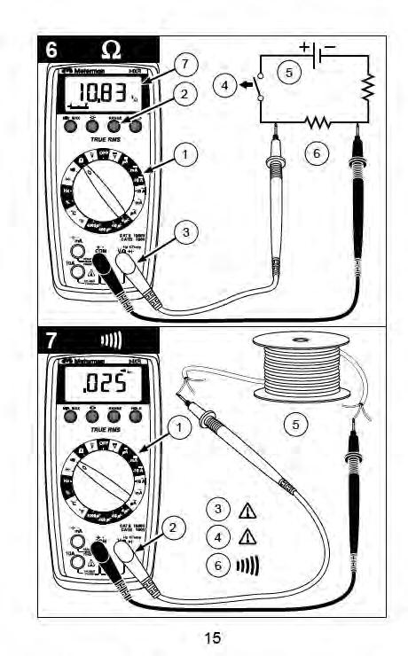
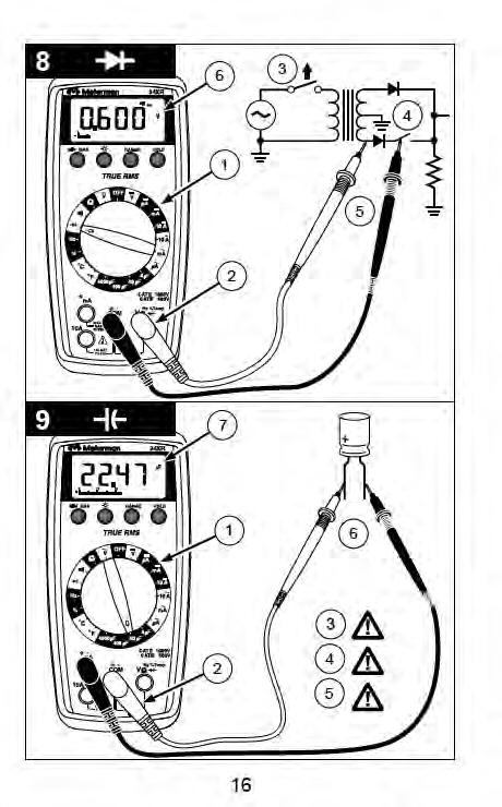
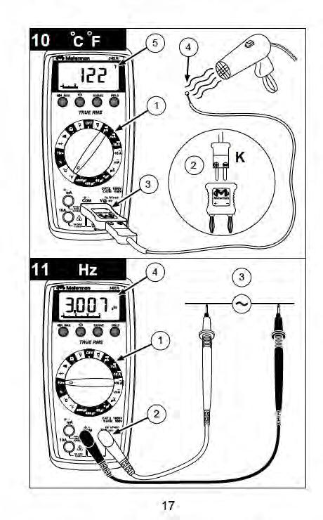
7 Measuring Resistance See Figure Set the Function Switch to Ω. 2. If RANGE is displayed, press the RANGE button to enable autoranging. 3. Connect the Test Leads: Red to E, Black to COM 4. Turn off power to the circuit being measured. Never measure resistance across a voltage source or on a powered circuit. 5. Discharge any capacitors that may influence the reading. 6. Connect the Test Probes across the resistance. 7. Read the display. If o appears on the highest range, the resistance is too large to be measured. Measuring Continuity See Figure Set the Function Switch to R. 2. Connect the Test Leads: Red to E, Black to COM 3. Turn off power to the circuit being measured. 4. Discharge any capacitors that may influence the reading. 5. Connect the Test Probes across the resistance. 6. Listen for the tone that indicates continuity (< 35 Ω). Checking Diodes See Figure Set the Function Switch to G. 2. Connect the Test Leads: Red to E, Black to COM 3. Turn off power to the circuit being measured. 4. Free at least one end of the diode from the circuit. 5. Connect the Test Probes across the diode. 6. Read the display. A good diode has a forward voltage drop of about 0.6 V. An open or reverse biased diode will read o. Measuring Capacitance See Figure Set the Function Switch to an appropriate µf function and range. 2. Connect the Test Leads: Red to COM, Black to µa ma P(-) 3. Turn off power to the circuit being measured. 4. Discharge the capacitor using a 100 kω resistor. 5. Free at least one end of the capacitor from the circuit. 6. Connect the Test Probes across the capacitor. When measuring an electrolytic capacitor match the test lead polarity to the polarity of the capacitor. 7. Read the display. Measuring Temperature See Figure Set the Function Switch to C or F. 2. Connect the K-type thermocouple to a TEMP adapter (XR-TA). Match the polarity of the adapter to the polarity of the thermocouple. 3. Connect the TEMP adapter to the E and COM inputs. Note: The 34XR is compatible with all K-type thermocouples. The K-type bead thermocouple supplied with the meter is not intended for contact with liquids or electrical circuits. 4. Expose the thermocouple to the temperature to be measured. 5. Read the display. 5
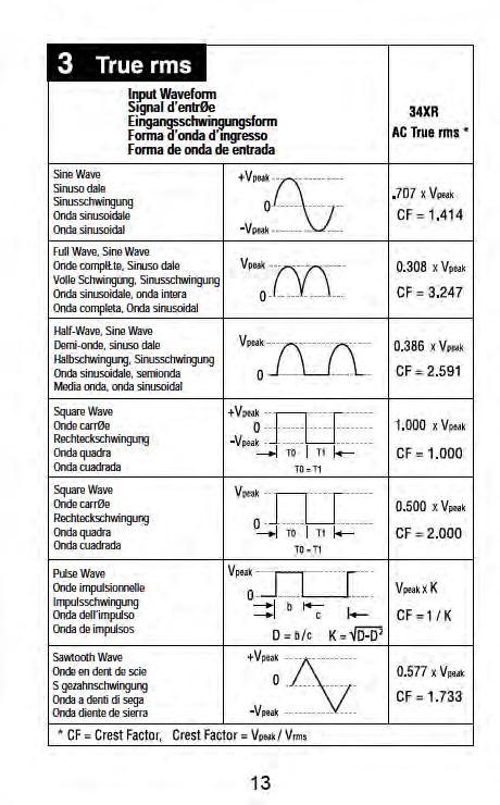
8 Measuring Frequency See Figure Set the Function Switch to Hz. 2. Connect the Test Leads: Red to Hz, Black to COM 3. Connect the Test Probes to the signal source. 4. Read the display. The Meter will autorange for the best resolution. Measuring Dutycycle See Figure Set the Function Switch to %. 2. Connect the Test Leads: Red to %, Black to COM 3. Connect the Test Probes to the signal source. 4. Read the display. The Meter will autorange for the best resolution. Additional Features Input Test Lead Warning The meter emits a continuous tone when a test lead is placed in the µa ma or 10A input jack and the Function/Range Switch is not set to a correct current position. (If the meter is connected to a voltage source with leads connected for current, very high current could result). All current ranges are protected by fast acting fuses. True-rms Measurements For ac measurements most DMMs average the ac input signal and display the result as an estimated rms value. This average-responding method is accurate for sinusoidal waveforms, but can be very inaccurate for distorted waveforms. To ensure the most accurate measurements, always use a true-rms DMM when measuring ac voltage or ac current on circuits for the following kinds of applications: Power Supplies - diodes Controllers Power Limiting - SCR or Triac Starting - motors Florescent Lighting - ballasts Speed Control - motors Pulsed Signals Any non-sinusoidal ac waveform MIN MAX Measurements The MIN MAX function reads and updates the display to show the maximum or minimum value measured after you press the MIN MAX button. Pressing the MIN MAX button for less than 1 second will put the meter into a mode of displaying the maximum, minimum, or actual readings. Each time the button is pressed, the meter will cycle to the next display mode as shown in the table below. Press the MIN MAX button for more than 2 seconds to exit MIN MAX. Button Display Value Displayed < 1 second MAX Maximum value after feature activated < 1 second MIN Minimum value after feature activated < 1 second MIN MAX (blinks) Normal measurement, actual reading > 2 seconds Exit MIN MAX Normal measurement, actual reading 6
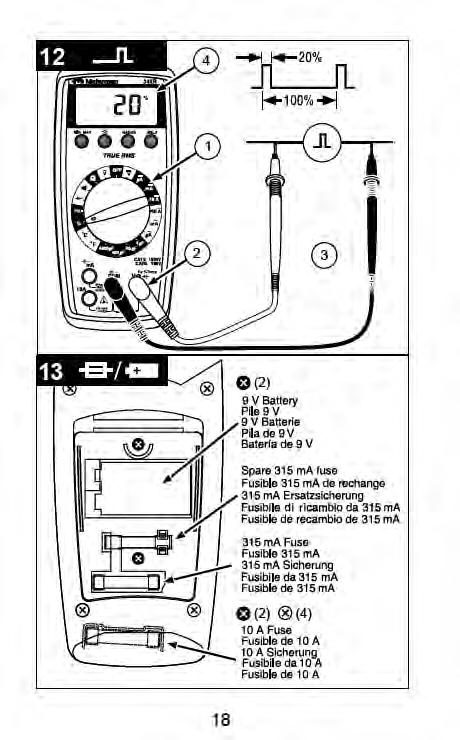
9 Auto Power Off Auto Power Off is a battery saving feature that puts the meter into a sleep mode if the Function/Range Switch has not changed position in the last 30 minutes. To wake the meter turn it off and then on. The Auto Power Off feature can be disabled to keep the meter from going to sleep. This feature is useful when using the MIN MAX mode for extended periods. To disable the Auto Power Off feature use the following procedure: 1. Set the Function Switch to OFF. 2. Press and hold the MIN MAX button while turning the Function Switch to the desired function. 3. Continue to press the MIN MAX button until the display finishes this initialization period and the reading settles. 4. Release the MIN MAX button. The Auto Power Off feature will remain disabled until the meter is turned off and then on. HOLD Measurements The HOLD button causes the meter to capture and continuously display a measurement reading. To use the HOLD feature make a measurement, and then, after the reading has stabilized, momentarily press the HOLD button. You can remove the test leads and the reading will remain on the display. Pressing the HOLD button again releases the display. Backlight Pressing the L button illuminates the display with a blue backlight. The backlight will automatically turn off in about 60 seconds. Frequent use of the backlight will decrease battery life. Product Maintenance Cleaning To clean the meter, use a soft cloth moistened with water. To avoid damage to the plastic components do not use benzene, alcohol, acetone, ether, paint thinner, lacquer thinner, ketone or other solvents to clean the meter. Troubleshooting If the meter appears to operate improperly, check the following items first. 1. Review the operating instructions to ensure the meter is being used properly. 2. Inspect and test the continuity of the test leads. 3. Make sure the battery is in good condition. The low battery symbol B appears when the battery falls below the level where accuracy is guaranteed. Replace a low-battery immediately. 4. Check the condition of the fuses if the current ranges operate incorrectly. Battery and Fuse Replacement See Figure -13- XWWARNING To avoid electrical shock remove the test leads from both the meter and the test circuit before accessing the battery or the fuses. 7
10 To access the battery and the ma fuse remove the two screws holding the Battery/Fuse Cover in place, and lift the cover from the meter. To replace the ma fuse, pry it from its clips using a small screwdriver. A spare ma fuse is located between the battery and the ma fuse. ma Fuse: Fast Blow 315mA/1000V, minimum interrupt rating 30 ka (6.3 x 32 mm) (Meterman FP300) To replace the 10 A fuse: 1) Remove the battery. 2) Remove the four rear-case screws. 3) Separate the case. 4) Remove the 10 A fuse cover. 5) Remove and replace the 10A fuse. 6) Re-install the fuse cover. 7) Reassemble the meter. 10A Fuse: Fast Blow 10A/1000V, minimum interrupt rating 30 ka (10 x 38 mm) (Meterman FP100). Repair All test tools returned for warranty or non-warranty repair or for calibration should be accompanied by the following: your name, company s name, address, telephone number, and proof of purchase. Additionally, please include a brief description of the problem or the service requested and include the test leads with the meter. Non-warranty repair or replacement charges should be remitted in the form of a check, a money order, credit card with expiration date, or a purchase order made payable to Meterman Test Tools. In-Warranty Repairs and Replacement All Countries Please read the warranty statement located at the front of this manual and check your batteries and fuses before requesting repair. During the warranty period any defective test tool can be returned to your Meterman Test Tools distributor for an exchange for the same or like product. Please check the Where to Buy section on for a list of distributors near you. Additionally, in the United States and Canada In-Warranty repair and replacement units can also be sent to a Meterman Test Tools Service Center (see below for address). Non-Warranty Repairs and Replacement US and Canada Non-warranty repairs in the United States and Canada should be sent to a Meterman Test Tools Service Center. Call Meterman Test Tools or inquire at your point of purchase for current repair and replacement rates. In USA In Canada Meterman Test Tools Meterman Test Tools th Street SW 400 Britannia Rd. E. Unit #1 Everett, WA Mississauga, ON L4Z 1X9 Tel: Tel: Fax: Fax: Non-Warranty Repairs and Replacement Europe European non-warranty units can be replaced by your Meterman Test Tools distributor for a nominal charge. Please check the Where to Buy section on for a list of distributors near you. European Correspondence Address* Meterman Test Tools Europe P.O. Box BD Eindhoven The Netherlands *(Correspondence only no repair or replacement available from this address. European customers please contact your distributor.) 8
11 WARRANTY This 34XR Digital Multimeter is warranted against any defects of material or workmanship within a period of three (3) years following the date of purchase of the multimeter by the original purchaser or original user. Any multimeter claimed to be defective during the warranty period should be returned with proof of purchase to an authorized Meterman Test Tools Service Center or to the local Meterman Test Tools dealer or distributor where your multimeter was purchased. See Repair section for details. Any implied warranties arising out of the sale of a Meterman Test Tools multimeter, including but not limited to implied warranties of merchantability and fitness for a particular purpose, are limited in duration to the above stated three (3) year period. Meterman Test Tools shall not be liable for loss of use of the multimeter or other incidental or consequential damages, expenses, or economical loss or for any claim or claims for such damage, expenses or economical loss. Some states do not allow limitations on how long implied warranties last or the exclusion or limitation of incidental or consequential damages, so the above limitations or exclusions may not apply to you. This warranty gives you specific legal rights, and you may also have other rights which vary from state to state. Specifications General Specifications Display: 3 ¾ digit liquid crystal display (LCD)(3999 count) with a 41-segment analog bar-graph. Polarity: Automatic, positive implied, negative polarity indication. Overrange: (0o) or (-0o) is displayed. Zero: Automatic. Low battery indication: The B is displayed when the battery voltage drops below the operating level. Auto power off: Approx. 30 minutes. Measurement rate: 2 times per second, nominal. Operating environment: 0 C to 45 C at <70 % R.H. Storage temperature: -20 C to 60 C, 0 to 80 % R.H. with battery removed from meter. Temperature Coefficient: 0.1 (specified accuracy) per C. (0 C to 18 C, 28 C to 45 C). Altitude: 2000 m (6562 feet) Power: Single standard 9-volt battery, NEDA 1604, JIS 006P, IEC 6F22. Battery life: 100 hours typical with carbon-zinc. 200 hours typical with alkaline. Frequent use of the backlight will decrease battery life. Dimensions: 196 mm (H) 92 mm (W) 60 mm (D). Weight: Approximately 400 g including battery. Box contents: The 34XR includes the following items: Test leads w/ alligator clips 1 set Holster 1 Magnet Strap 1 Temperature Adapter 1 K-type thermocouple 1 Users Manual 1 9 V battery (installed) 1 ma fuse, A/ 1000 V 1 spare 9
12 Approvals: LISTED 950Z Safety: Conforms to UL1244; EN : Cat II V / Cat III - 600V; Class 2, Pollution degree II. EMC: Conforms to EN , criteria B This product complies with requirements of the following European Community Directives: 89/ 336/ EEC (Electromagnetic Compatibility) and 73/ 23/ EEC (Low Voltage) as amended by 93/ 68/ EEC (CE Marking). However, electrical noise or intense electromagnetic fields in the vicinity of the equipment may disturb the measurement circuit. Measuring instruments will also respond to unwanted signals that may be present within the measurement circuit. Users should exercise care and take appropriate precautions to avoid misleading results when making measurements in the presence of electronic interference. Electrical Specifications (Accuracy at 23 C ±5 C, <75 % relative humidity) DC VOLTS Ranges: 400mV, 4V, 40V, 400V, 1000V Resolution: 100 µv in 400mV range Accuracy: ±(0.5 % rdg + 1 dgt) Input impedance: 400mV: >100 MΩ; 4V: 10 MΩ; 40V to 1000V: 9.1 MΩ Overload protection: 1000 V dc / 750 Vac rms AC VOLTS true rms (45Hz - 2kHz) Ranges: 400m, 4V, 40V, 400V, 750V Resolution: 100 µv Accuracy: ±(1.2 % rdg +8 dgts) 45 Hz to 100 Hz on 400mV range ±(1.2 % rdg + 8 dgts) 45 Hz to 500 Hz ±(2.0 % rdg +8 dgts) 500 Hz to 2 khz ±(2.0 % rdg + 8 dgts) 45 Hz to 1 khz on 750 V range Crest Factor: 3 Input impedance: 400mV: >100 MΩ; 4V: 10 MΩ; 40V to 1000V: 9.1 MΩ AC coupled true rms specified from 5 % to 100 % of range Overload protection: 1000 V dc or 750 V ac rms DC CURRENT Ranges: 400µA, 4000µA, 40mA, 300mA, 10A Resolution: 0.1µA Accuracy: ±(1.0 % rdg + 1 dgt) on 400µA to 300mA ranges ±(2.0 % rdg + 3 dgts) on 10A range Burden voltage: 400 µa Range: 1 mv/ 1 µa 4 ma Range: 500 mv/ 1 ma 40 ma Range: 10 mv/ 1 ma 300 ma: 8 mv/ 1 ma 10A: 40 mv/ 1 A Input protection: 0.315A/1000V fast blow ceramic fuse mm on µa/ma input 10A/1000V fast blow ceramic fuse 10 38mm on 10A input 10A input: 10 A for 4 minutes maximum followed by a 12 minute cooling period AC CURRENT true rms (45Hz - 1kHz) Ranges: 400µA, 4000µA, 40mA, 300mA, 10A Resolution: 0.1 µa Accuracy: ±(1.5 % rdg + 8 dgts) on 400µA to 300mA ranges ±(2.5 % rdg + 10 dgts) on 10A range Crest Factor: 3 Burden Voltage: See DC Current Input protection: 0.315A/1000V fast blow ceramic fuse mm on µa/ma input 10A/1000V fast blow ceramic fuse 10 38mm on 10A input 10A input: 10 A for 4 minutes maximum followed by a 12 minute cooling period 10
13 RESISTANCE Ranges: 400Ω, 4kΩ, 40kΩ, 400kΩ, 4MΩ, 40MΩ Resolution: 100 mω Accuracy: ±(1.0 % rdg + 4 dgts) on 400Ω to 4MΩ ranges ±(2.0 % rdg + 5 dgts) on 40MΩ range Open circuit volts: V dc typical, (-1.2 V dc on 400Ω range) Overload protection: 1000 V dc or 750 V ac rms CAPACITANCE Ranges: 4µF, 40µF, 400µF, 4000µF Resolution: 1 nf Accuracy: ±(5.0 % rdg + 10 dgts) on 4µF range ±(5.0 % rdg + 5 dgts) on 40µF to 400µF ranges ±(5.0 % rdg + 15 dgts) on 4000µF range Test voltange: < 3.0 V Test Frequency: 25Hz Input protection: 0.315A/1000V fast blow ceramic fuse mm on µa/ma input TEMPERATURE Ranges: -20 C to 1000 C, -4 F to 1832 F Resolution: 1 C, 1 F Accuracy: ±(2.0 % rdg + 4 C) -20 C to 10 C ±(1.0 % rdg + 3 C) 10 C to 200 C ±(3.0 % rdg + 2 C) 200 C to 1000 C ±(2.0 % rdg + 8 F) -4 F to 50 F ±(1.0 % rdg + 6 F) 50 F to 400 F ±(3.0 % rdg + 4 F) 400 F to 1832 F Overload protection: 1000 V dc or 750 V ac rms FREQUENCY Ranges: 4k, 40k, 400k, 4M, 40MHz Resolution: 1 Hz Accuracy: ±(0.1 % rdg + 3 dgts) Sensitivity: 10 Hz to 4 MHz: >1.5 V ac rms; 4 MHz to 40 MHz: >2 V ac rms, <5 V ac rms Minimum pulse width: > 25 ns Duty cycle limits: > 30 % and < 70 % Overload protection: 1000 V dc or 750 V ac rms DUTY CYCLE Ranges: 0 to 90 % Resolution: 0.1 % Pulse widh: >10 µs Frequency range: 40 Hz to 20 khz Accuracy: (5V logic ) ±(2.0% rdg + 5 dgts) Overload protection: 1000 V dc or 750 V ac rms CONTINUITY Audible indication: < 35 Ω Response time: 100 ms Overload protection:1000 V dc or 750 V ac rms DIODE TEST Test current: approximately 1.2 ma Accuracy: ±(1.5 % rdg + 3 dgts) Resolution: 1 mv Open circuit volts: 3.0 V dc typical Overload protection: 1000 V dc or 750 V ac rms ADDITIONAL FEATURES µa ma, 10A Test Lead Connection: Beeps to warn test leads are connected to measure current while Function/Range Switch is not set to a measure current. MIN MAX: Displays the minimum or maximum value detected while making a measurement. HOLD: Holds the latest reading on the display. RANGE: Manual range mode. Backlight: Backlight auto-off approximately 60 seconds Auto Power off: 30 minutes, typical REPLACEMENT PARTS TL36 Test Lead Set with Alligator clips FP300 ma fuse - Fuse Pack.315A/1000V (4 each) FP100 10A fuse - Fuse Pack 10A/1000V (2 each) XR-TA Input Adapter for K-type thermocouple TP255 K type thermocouple XR-H2 Magne-Grip Holster, clip, magnet, and strap 11
14
15
16
17
18
19
20
21 19
22
Supplement. Title: 33XR-A Users Supplement Issue: 1 Part Number: Issue Date: 9/06 Print Date: July 2006 Page Count: 1 Revision/Date:
 Supplement Title: Users Supplement Issue: 1 Part Number: 7891 Issue Date: 9/06 Print Date: July 006 Page Count: 1 Revision/Date: This supplement contains information necessary to ensure the accuracy of
30XR-A Professional Digital Multimeter Users Manual
 Professional Digital Multimeter Users Manual 99 Washington Street Melrose, MA 076 Fax 78-665-0780 TestEquipmentDepot.com MADE IN TAIWAN PATENTS PENDING www.amprobe.com MIN 5 00 00 0 0 00m 00m 00 0M m M
Supplement. Title: 30XR-A Users Supplement Issue: 1 Part Number: Issue Date: 9/06 Print Date: July 2006 Page Count: 1 Revision/Date:
 Supplement Title: Users Supplement Issue: Part Number: 7897 Issue Date: 9/06 Print Date: July 006 Page Count: Revision/Date: This supplement contains information necessary to ensure the accuracy of the
Supplement. Title: 34XR-A Users Supplement Issue: 2 Part Number: Issue Date: 9/06 Print Date: July 2006 Page Count: 1 Revision/Date:
 Supplement Title: Users Supplement Issue: Part Number: 7899 Issue Date: 9/06 Print Date: July 006 Page Count: Revision/Date: This supplement contains information necessary to ensure the accuracy of the
5XP-A 15XP-A 35XP-A Compact Digital Multimeters
 XP- XP- XP- Compact Digital Multimeters English Users Manual 99 Washington Street Melrose, M 076 Fax 78-66-0780 TestEquipmentDepot.com MX XP- RNGE CONTCT OLTGE m m C 000 8 F MX 000 70 CT 000 CT 600 CT
Circuit Breaker Finder
 ECB50-FGIS Circuit Breaker Finder and AC Line Tracer User Manual ECB50-FGIS Circuit Breaker Finder and AC Cable Tracer Contents Safety Information...3 Symbols Used in this Manual...3 Introduction...4 Finding
AC68C. Users Manual. True RMS AC/DC Clamp Multimeter. PN July Amprobe Test Tools. All rights reserved.
 AC68C True RMS AC/DC Clamp Multimeter Users Manual PN 2729051 July 2006 2006 Amprobe Test Tools. All rights reserved. Printed in Taiwan For detailed specifications and ordering info go to www.testequipmentdepot.com
USER'S MANUAL DMR-6700
 USER'S MANUAL Multimeter True RMS DMR-6700 CIRCUIT-TEST ELECTRONICS www.circuittest.com Introduction This meter measures AC/DC Voltage, AC/DC Current, Resistance, Capacitance, Frequency (electrical & electronic),
IDEAL INDUSTRIES, INC. TECHNICAL MANUAL MODEL: MODEL: Multimeter Service Information
 IDEAL INDUSTRIES, INC. TECHNICAL MANUAL MODEL: 61-340 MODEL: 61-342 Multimeter Service Information The Service Information provides the following information: Precautions and safety information Specifications
Autoranging Multimeter Extech EX503
 User's Guide Autoranging Multimeter Extech EX503 Introduction Congratulations on your purchase of the Extech EX503 Autoranging Multimeter. This meter measures AC/DC Voltage, AC/DC Current, Resistance,
DM-45 Digital Multimeter
 INSTRUCTION MANUAL DM-45 Digital Multimeter Read and understand all of the instructions and safety information in this manual before operating or servicing this tool. Description The Greenlee DM-45 Digital
User s Manual. MiniTec TM Series. Model MN26 (Model MN26T includes temperature probe) Mini Autoranging MultiMeter
 Mini Autoranging MultiMeter") User s Manual MiniTec TM Series Model MN26 (Model MN26T includes temperature probe) Mini Autoranging MultiMeter Introduction Congratulations on your purchase of Extech s MN26 Autoranging Multimeter. This
User s Manual MiniTec TM Series Model MN26 (Model MN26T includes temperature probe) Mini Autoranging MultiMeter Introduction Congratulations on your purchase of Extech s MN26 Autoranging Multimeter. This
AC/DC CLAMP METER USER S MANUAL
 AC/DC CLAMP METER USER S MANUAL CONTENTS PAGE SAFETY INFORMATION SYMBOL EXPLANATION SAFETY PRECAUTIONS 1 1 2 MAINTENANCE 3 GENERAL DESCRIPTION 4 PANEL DESCRIPTION 4 OPERATING INSTRUCTIONS... 7 SPECIFICATIONS
AM-500 Autoranging Mulitmeter. AM-500-EUR Digital Multimeter. Users Manual
 AM-500 Autoranging Mulitmeter AM-500-EUR Digital Multimeter Users Manual AM-500 Autoranging Mulitmeter AM-500-EUR Digital Multimeter English Users Manual 8/2012, 4275548 A 2012 Amprobe Test Tools. All
For detailed specifications and ordering info go to
 For detailed specifications and ordering info go to www.testequipmentdepot.com ECB50A, ECB50A-E, ECB50A-FGIS Circuit Breaker Finder and AC Cable Tracer User Manual For detailed specifications and ordering
Fluke 83V and 87V Digital Multimeters
 Fluke 83V and 87V Digital Multimeters Detailed Specifications For all detailed specifications: is given as ±([% of reading] + [number of least significant digits]) at 18 C to 28 C, with relative humidity
Model ST Instruction Manual. True RMS Autoranging Digital Multimeter. reedinstruments. www. com
 Model ST-9933 True RMS Autoranging Digital Multimeter Instruction Manual reedinstruments com Table of Contents Safety... 3 Features... 4 Specifications...4-8 Technical...4-5 Accuracy...5-8 Display Description...
DVM645BI BENCH MULTIMETER TAFELMULTIMETER MULTIMETRE DE TABLE BANCO MULTÍMETRO TISCHMULTIMETER. User Manual. Gebruikershandleiding
 BENCH MULTIMETER TAFELMULTIMETER MULTIMETRE DE TABLE BANCO MULTÍMETRO TISCHMULTIMETER User Manual Gebruikershandleiding Manuel d'utilisation Gebrauchsanleitung Introduction BENCH MULTIMETER This manual
AM-510 Commercial / Residential Multimeter. AM-510-EUR Digital Multimeter. Users Manual
 AM-510 Commercial / Residential Multimeter AM-510-EUR Digital Multimeter Users Manual AM-510 Commercial / Residential Multimeter AM-510-EUR Digital Multimeter English Users Manual Limited Warranty and
INSTRUCTION MANUAL. Model Autoranging DMM ProbeMeter TM. Measures voltage, resistance, frequency, capacitance, temperature, and duty cycle.
 INSTRUCTION MANUAL Model 403380 Autoranging DMM ProbeMeter TM Measures voltage, resistance, frequency, capacitance, temperature, and duty cycle. Back lit LCD with Autorange and full function displays Audible
IDEAL INDUSTRIES, INC. TECHNICAL MANUAL MODEL:
 IDEAL INDUSTRIES, INC. TECHNICAL MANUAL MODEL: 61-352 The Service Information provides the following information: Precautions and safety information Specifications Basic maintenance (cleaning, replacing
79/26 Series III Multimeter
 79/26 Series III Multimeter Instruction Sheet W Read First: Safety Information Never use the meter if the meter or test leads look damaged. Be sure the test leads and switch are in the correct position
1587/1577 Insulation Multimeters
 1587/1577 Insulation Multimeters Technical Data Two powerful tools in one. The Fluke 1587 and 1577 Insulation Multimeters combine a digital insulation tester with a full-featured, true-rms digital multimeter
User s Guide. 400A AC/DC Clamp Meter. Model MA220
 User s Guide 400A AC/DC Clamp Meter Model MA220 Introduction Thank you for selecting the Extech MA200 AC/DC Clamp Meter. This meter measures AC/DC Current, AC/DC Voltage, Resistance, Capacitance, Frequency,
PM55A. Automatic Precision Pocket Meter. English. Users Manual. PN July Amprobe Test Tools. All rights reserved.
 PM55A Automatic Precision Pocket Meter Users Manual English PN 2728864 July 2006 2006 Amprobe Test Tools. All rights reserved. Printed in Taiwan For detailed specifications and ordering info go to www.testequipmentdepot.com
MM700. True RMS ENGLISH. INSTRUCTION MANUAL Auto-Ranging. Measurement Technology
 INSTRUCTION MANUAL Auto-Ranging Digital Multimeter er True RMS Measurement Technology MM700 DATA & RANGE HOLD LOW IMPEDANCE AUDIBLE CONTINUITY MIN / MAX / RELATIVE TEMPERATURE DIODE TEST CAPACITANCE &
ACD-3300 IND ACDC-3400 IND
 ACD-3300 IND ACDC-3400 IND CAT IV Industrial True RMS Clamp Meters Users Manual Mode d emploi edienungshandbuch Manuale d Uso Manual de uso Användarhandbok 99 Washington Street Melrose, MA 02176 Phone
600A Clamp Meters w/tightsight Display
 V 750V #61-764 #61-766 #61-768 600A Clamp Meters w/tightsight Display Instruction Manual 99 Washington Street Melrose, MA 02176 Fax 781-665-0780 TestEquipmentDepot.com CAT.IV 600V CAT.III 1000V 600A 61-766
DVM1190 DIGITAL MULTIMETER
 DIGITAL MULTIMETER 1. Introduction Thank you for buying the. This digital multimeter has a large LCD, a data-hold function and a backlight. The device uses a very practical safety mechanism that keeps
200Amp AC Clamp Meter + NCV Model MA250
 User's Guide 200Amp AC Clamp Meter + NCV Model MA250 Introduction Congratulations on your purchase of this Extech MA250 Clamp Meter. This meter measures AC Current, AC/DC Voltage, Resistance, Capacitance,
MM700. INSTRUCTION MANUAL Auto-Ranging Digital Multimeter True RMS
 INSTRUCTION MANUAL Auto-Ranging Digital Multimeter True RMS Measurement Technology MM700 DATA & RANGE HOLD LOW IMPEDANCE AUDIBLE CONTINUITY MIN / MAX / RELATIVE TEMPERATURE DIODE TEST CAPACITANCE & FREQUENCY
User's Guide Mini Multimeter with Non-Contact Voltage Detector (NCV) Model EX330
 Model EX330") User's Guide Mini Multimeter with Non-Contact Voltage Detector (NCV) Model EX330 Introduction Congratulations on your purchase of the Extech EX330 Meter. The EX330 offers AC/DC Voltage, AC/DC Current,
User's Guide Mini Multimeter with Non-Contact Voltage Detector (NCV) Model EX330 Introduction Congratulations on your purchase of the Extech EX330 Meter. The EX330 offers AC/DC Voltage, AC/DC Current,
Compact Autoranging Clamp Meters. Models (400 A AC), (400 A AC/DC)
, (400 A AC/DC)") User Manual Compact Autoranging Clamp Meters with NIST-Traceable Calibration Models 20250-55 (400 A AC), 20250-56 (400 A AC/DC) THE STANDARD IN PRECISION MEASUREMENT 1065DGMAN_20250-55,-56 DS Clamp Meter
User Manual Compact Autoranging Clamp Meters with NIST-Traceable Calibration Models 20250-55 (400 A AC), 20250-56 (400 A AC/DC) THE STANDARD IN PRECISION MEASUREMENT 1065DGMAN_20250-55,-56 DS Clamp Meter
MW3105 DIGITAL CLAMP MULTIMETER
 MW3105 DIGITAL CLAMP MULTIMETER 2 M MW3105 A 01 INTRODUCTION 1.1 - Unpacking and inspection Upon removing your new Digital Clamp Meter from its packing, you should have the following items: 1. Digital
1.General instructions Specifications Description...7
 USER S Manual CONTENTS 1.General instructions...1 1.1 Precautions safety measures...1 1.1.1 Preliminary...1 1.1.2 During use...2 1.1.3 Symbols...4 1.1.4 Instructions...5 1.2 Protection mechanisms...6 2.
Electrical Multimeter
 113 Electrical Multimeter Instruction Sheet Safety Information A Warning statement identifies hazardous conditions and actions that could cause bodily harm or death. A Caution statement identifies conditions
USER MANUAL 600A AC Clamp Meter + NCV Model MA610
 USER MANUAL 600A AC Clamp Meter + NCV Model MA610 Additional User Manual Translations available at www.extech.com Introduction Thank you for selecting the Extech MA610 Clamp Meter. This meter measures
NOTE: Fully read and understand this manual before using this Digital Multimeter.
 ASTROAI USER MANUAL AUTO RANGING DIGITAL CLAMP METER Thank you for purchasing the Auto Ranging Digital Clamp Meter from AstroAI. The AstroAI Auto Ranging Digital Clamp Meter is designed to be safely and
USER'S MANUAL ACDC-100 TRMS ACDC-100. Versatile AC/DC Clamp-on Multimeter Series
 99 Washington Street Melrose, MA 02176 Fax 781-665-0780 TestEquipmentDepot.com USER'S MANUAL ACDC-100 TRMS ACDC-100 Versatile AC/DC Clamp-on Multimeter Series 1 1) SAFETY This manual contains information
AC/DC Clamp Meter. Owner's Manual. Model No Safety Operation Maintenance Español
 Owner's Manual AC/DC Clamp Meter Model No. 82369 CAUTION: Read, understand and follow Safety Rules and Operating Instructions in this manual before using this product. Safety Operation Maintenance Español
99 Washington Street Melrose, MA Fax TestEquipmentDepot.com # # AAC Clamp Meter. Instruction Manual
 99 Washington Street Melrose, MA 02176 Fax 781-665-0780 TestEquipmentDepot.com #61-732 #61-736 400 AAC Clamp Meter Instruction Manual AC HOLD APO DC KMΩ mva WARNING Read First: Safety Information Understand
AUTORANGING TRUE RMS MULTIMETER USER GUIDE. INST151 Doc 1.00
 AUTORANGING TRUE RMS MULTIMETER USER GUIDE INST151 Doc 1.00 CONTENTS General Information...2 Safety...3 Controls and Jacks...7 Symbols and Annunicators...8 Operating Instructions...9 Maintenance...18
EX350 Series USER GUIDE. True RMS Digital Multimeters. EX350 True RMS Digital Multimeter EX355 True RMS Digital Multimeter with Temperature
 USER GUIDE True RMS Digital Multimeters EX350 Series EX350 True RMS Digital Multimeter EX355 True RMS Digital Multimeter with Temperature Table of Contents 1. INTRODUCTION 3 2. SAFETY INFORMATION 4 3.
Thank you again for choosing AstroAI, if you have any questions or concerns regarding your product, please contact us at
 ASTROAI USER MANUAL DT132A 4000 Count Auto-Ranging Multimeter Thank you for purchasing the AstroAI DT132A 4000 Count Auto-Ranging Multimeter. It is a 3 ¾ digit, 3999 counts, auto-ranging digital multimeter.
OPERATOR S INSTRUCTION MANUAL
 OPERATOR S INSTRUCTION MANUAL AUTO-RANGE DUAL DISPLAY CONFORMED IEC1010 DIGITAL MULTIMETER CONTENTS PAGE SAFETY INFORMATION..... DESCRIPTION.. OPERATING INSTRUCTION.. SPECIFICATIONS.... ACCESSORIES. BATTERY
ETHOS 5030 TRUE-RMS DIGITAL MULTIMETER OPERATION MANUAL
 ETHOS 5030 TRUE-RMS DIGITAL MULTIMETER OPERATION MANUAL 1 1. SAFETY INFORMATION SAFETY SYMBOLS Warning! Dangerous Voltage (Risk of electric shock). Caution! Refer to the user s manual before using this
312, 316, 318. Clamp Meter. Users Manual
 312, 316, 318 Clamp Meter Users Manual PN 1989445 July 2002 Rev.2, 2/06 2002, 2006 Fluke Corporation. All rights reserved. Printed in China. All product names are trademarks of their respective companies.
OPERATING INSTRUCTION
 OPERATING INSTRUCTION AUTOMOTIVE MULTIMETER MODEL QM1444 the finger guards on the probes. Measuring voltage which exceeds the limits of the multimeter may damage the meter and expose the operator to a
MM V 10A ENGLISH. INSTRUCTION MANUAL Auto-Ranging DATA HOLD AUDIBLE CONTINUITY MIN / MAX TEMPERATURE DIODE TEST CAPACITANCE
 INSTRUCTION MANUAL Auto-Ranging Digital Multimeter MM400 DATA HOLD AUDIBLE CONTINUITY MIN / MAX TEMPERATURE DIODE TEST CAPACITANCE 600V 10A 40MΩ 2 GENERAL SPECIFICATIONS Klein Tools MM400 is an auto-ranging
DVM98. True RMS Digital Multimeter. 1 Safety information. 1.1 Preliminary. 1.2 During use
 True RMS Digital Multimeter DVM98 1 Safety information This multimeter has been designed according to IEC - 1010 concerning electronic measuring instruments with an overvoltage category (CAT II) and pollution
400Amp True RMS AC/DC Clamp Meter Model EX613
 User's Guide 400Amp True RMS AC/DC Clamp Meter Model EX613 Introduction Congratulations on your purchase of this Extech EX613 True RMS Clamp Meter. This meter measures AC Current, DC Current, AC/DC Voltage,
CD770 DIGITAL MULTIMETER INSTRUCTION MANUAL
 CD770 DIGITAL MULTIMETER INSTRUCTION MANUAL Table of Contents 1 SAFETY PRECAUTIONS Before use, read the following safety precautions.- 1-1 Explanation of Warning Symbols 001 1-2 Warning Messages for Safe
OPERATOR S INSTRUCTION MANUAL M-2625 AUTO RANGING DIGITAL MULTIMETER
 OPERATOR S INSTRUCTION MANUAL M-2625 AUTO RANGING DIGITAL MULTIMETER with Temperature Probe Copyright 2007 Elenco Electronics, Inc. Contents 1. Safety Information 3,4 2. Safety Symbols 5 3. Front Plate
Safety. This symbol, adjacent to a terminal, indicates that, under normal use, hazardous voltages may be present.
 9305 Safety International Safety Symbols This symbol, adjacent to another symbol or terminal, indicates the user must refer to the manual for further information. This symbol, adjacent to a terminal, indicates
MS2030 CAT III 600 V A V AUTO RS232
 MS2030 AC Digital Clamp Meter User s Manual CAT III 600 V AUTO RS232 A V CONTENTS 1.Introduction...1 2.Safety Information...1 2.1 Precautions...1 2.2 Safety Symbols...3 3. Description...4 3.1 Front Panel...4
Fluke 170 Series True-rms Digital Multimeters
 TECHNICAL DATA Fluke 170 Series True-rms Digital Multimeters Fluke 170 Series DMMs are the industry-standard troubleshooting tools for electrical and electronic systems Fluke 170 Series digital multimeters
DDM350 Pen-Type Digital Multimeter User s Manual
 DDM350 Pen-Type Digital Multimeter User s Manual CONTENTS LIMITED WARRANTY AND LIMITATION OF LIABILITY....1 Out of the Box...1 Accessories......2 Safety Information...2 Safety Symbols...3 Certification......4
User Manual Digital Multimeter
 User Manual Digital Multimeter model no.: MSR-R500 Questions or Concerns? support@etekcity.com visit etekcity.com for more products Safe and Proper Usage Thank you for purchasing the Etekcity MSR-R500
Digital Clamp Meter (TRMS) Model : 2727
 Model : 2727") Digital Clamp Meter (TRMS) Model : 2727 Instruction Manual 1. SPECIFICATIONS 1.1 General Specifications Display : 3 ¾ digit liquid crystal display (LCD) with a maximum reading of 3999. Polarity : Automatic,
Digital Clamp Meter (TRMS) Model : 2727 Instruction Manual 1. SPECIFICATIONS 1.1 General Specifications Display : 3 ¾ digit liquid crystal display (LCD) with a maximum reading of 3999. Polarity : Automatic,
Model 77 Series IV. Digital Multimeter. Users Manual
 Model 77 Series IV Digital Multimeter Users Manual Model 77 Series IV Digital Multimeter The Fluke Model 77 Series IV is a battery-powered, average responding-rms indicating multimeter (hereafter "the
BENNING. Service Information MODEL: MM1-1 / MM1-2 / MM1-3
 BENNING MODEL: MM1-1 / MM1-2 / MM1-3 Service Information The Service Information provides the following information: Precautions and safety information Specifications Basic maintenance (cleaning, replacing
PEN TYPE DIGITAL MULTIMETER OPERATION MANUAL T8211D
 PEN TYPE DIGITAL MULTIMETER OPERATION MANUAL T8211D T8211D 1 1. SAFETY INFORMATION BE EXTREMELY CAREFUL IN THE USE OF THIS METER. Improper use of this device can result in electric shock or destroy of
USER'S MANUAL AM-100 AM-105 TRMS AM-110 TRMS. Digital Multimeters
 USER'S MANUAL AM-100 AM-105 TRMS AM-110 TRMS Digital Multimeters 1 1) SAFETY This manual contains information and warnings that must be followed for operating the instrument safely and maintaining the
12B/18 MultiMeter Instruction Sheet
 12B/18 MultiMeter Instruction Sheet P Read First: Safety Information To ensure that the meter is used safely, follow these instructions: Do not use the meter if the meter or test leads appear damaged,
AMM-1022 Digital Multimeter USER`S MANUAL
 Digital Multimeter USER`S MANUAL www.tmatlantic.com CONTENTS 1. SAFETY INFORMATION.3 2. DESCRIPTION..6 3. SPECIFICATIONS.8 4. OPERATING INSTRUCTION..11 4.1 Voltage measurement...11 4.2 Current measurement
User's Guide. 800 Amp AC/DC True RMS Clamp Meter. Model EX Washington Street Melrose, MA Phone Toll Free
 User's Guide 99 Washington Street Melrose, MA 02176 Phone 781-665-1400 Toll Free 1-800-517-8431 Visit us at www.testequipmentdepot.com 800 Amp AC/DC True RMS Clamp Meter Model EX730 Introduction Congratulations
EX360 Series USER MANUAL. True RMS Digital Multimeters. EX360 True RMS Digital Multimeter EX363 True RMS DMM with Temperature and µa AC/DC
 USER MANUAL True RMS Digital Multimeters EX360 Series EX360 True RMS Digital Multimeter EX363 True RMS DMM with Temperature and µa AC/DC EX365 True RMS DMM with 10A AC/DC Current Additional User Manual
AT Advanced Wire Tracer. Users Manual
 AT-1000 Advanced Wire Tracer Users Manual AT-1000 Advanced Wire Tracer English Users Manual AT1000_Rev001 2008 Amprobe Test Tools. All rights reserved. Limited Warranty and Limitation of Liability Your
Pen Multimeter. Model
 Pen Multimeter Model 381626 CAUTION: Read, understand and follow all Safety Rules and Operating Instructions in this manual before using this product. This instrument is a 3200 count pen style digital
DM-46 Instruction Manual
 Auto Meter Products Inc. Test Equipment DM-46 Instruction Manual Automotive Multimeter and Inductive Amp Probe The DM-46 is the auto industry s answer to pocket portability in a 20 2650-1552-00 3/8/11
User s Guide. 400A AC/DC Clamp Meter. Model MA Washington Street Melrose, MA Phone Toll Free
 User s Guide 99 Washington Street Melrose, MA 02176 Phone 781-665-1400 Toll Free 1-800-517-8431 Visit us at www.testequipmentdepot.com 400A AC/DC Clamp Meter Model MA220 Introduction Thank you for selecting
MS8250D DUAL DISPLAY DIGITAL MULTIMETER User s Manual
 DUAL DISPLAY DIGITAL MULTIMETER User s Manual MS8250D 1. Safety Information Warning Use caution and follow all safety guidelines to prevent electric shock or damage to the meter. Please ready carefully
AM-520 AM-530. Users Manual. HVAC Multimeter. True-rms Electrical Contractor Multimeter
 AM-520 HVAC Multimeter AM-530 True-rms Electrical Contractor Multimeter Users Manual 99 Washington Street Melrose, MA 02176 Phone 781-665-1400 Toll Free 1-800-517-8431 Visit us at www.testequipmentdepot.com
USER'S MANUAL DMR-4350
 USER'S MANUAL DIGITAL MULTIMETER DMR-4350 CIRCUIT-TEST ELECTRONICS www.circuittest.com TABLE OF CONTENTS SAFETY Safety Information...................................... 2 Safety Symbols........................................
USER'S MANUAL DMR-4300
 USER'S MANUAL DIGITAL MULTIMETER DMR-4300 CIRCUIT-TEST ELECTRONICS www.circuittest.com TABLE OF CONTENTS SAFETY Safety Information...................................... 2 Safety Symbols........................................
AC/DC DIGITAL CLAMP METER OPERATION MANUAL
 AC/DC DIGITAL CLAMP METER OPERATION MANUAL HYS005661 A0 ACCESSORIES 6. ACCESSORIES 1) Test Leads: Electric Ratings 1000V 10A 1 pair (set) 2) Operating Manual 1 copy 3) 1.5V AAA Battery 3 piece - - 55 -
MS8250A/B OPERATION MANUAL MS8250A. Hz% FUNC REL RANGE REL HOLD OFF 10A. Hz% A NCV. Hz% COM. A ma 10A FUSED 600V CAT IV.
 MS8250A/B DIGITAL MULTIMETER OPERATION MANUAL AUTO DC AC REL hfe PCLINK % C F kmωkz nµmfav MS8250A DIGITAL MULTIMETER Auto Power Off RANGE REL HOLD FUNC NCV A ma OFF 10A A ma 10A FUSED 600V CAT IV COM
1587/1577. Insulation Multimeters. Technical Data. Two powerful tools in one.
 Test Equipment Depot - 800.517.8431-99 Washington Street Melrose, MA 02176 - TestEquipmentDepot.com 1587/1577 Insulation Multimeters Technical Data Two powerful tools in one. The Fluke 1587 and 1577 Insulation
USER MANUAL. Mini Multimeter with Non-Contact Voltage Detector (NCV) Model EX330
 Model EX330") USER MANUAL Mini Multimeter with Non-Contact Voltage Detector (NCV) Model EX330 Introduction Congratulations on your purchase of the Extech EX330 Meter. The EX330 offers AC/DC Voltage, AC/DC Current, Resistance,
USER MANUAL Mini Multimeter with Non-Contact Voltage Detector (NCV) Model EX330 Introduction Congratulations on your purchase of the Extech EX330 Meter. The EX330 offers AC/DC Voltage, AC/DC Current, Resistance,
INSTRUCTION MANUAL ACD-10 PRO & TRMS PRO
 INSTRUCTION MANUAL ACD-10 PRO & TRMS PRO AMPROBE 1 Congratulations! You are now the owner of an AMPROBE Instrument. It has been quality crafted according to quality standards and contains quality components
EM420A/420B DIGITAL MULTIMETER OWNERS MANUAL Read this owners manual thoroughly before use
 http://www.all-sun.com EM420A/420B DIGITAL MULTIMETER OWNERS MANUAL V Read this owners manual thoroughly before use WARRANTY This instrument is warranted to be free from defects in material and workmanship
DIGITAL MULTIMETER CONTENTS DIGITAL MULTIMETER CONTENTS
 CONTENTS CONTENTS CONTENTS 1. SAFETY INFORMATION...1 1.1 Preliminary...1 1.2 Dos and don ts...2 1.3 Symbols...3 1.4 Precautions...4 2. DESCRIPTION...5 2.1 Names of parts...6 2.2 Switches, buttons and input
374 FC/375 FC/376 FC Clamp Meter
 374 FC/375 FC/376 FC Clamp Meter PN 4705494 September 2015 2015 Fluke Corporation. All rights reserved. Specifications are subject to change without notice. All product names are trademarks of their respective
2000 A AC TRUE RMS DIGITAL CLAMP METER WITH NON-CONTACT EF-DETECTION
 An ISO 9001:2008 Company 2000 A AC TRUE RMS DIGITAL CLAMP METER WITH NON-CONTACT EF-DETECTION SPECIAL FEATURES : 2000A AC Clamp-on + Full Multimeter ranges AC True RMS Voltage & Current functions Autocheck
15B & 17B. Users Manual. Multimeters
 15B & 17B Multimeters Users Manual PN 1991246 October 2002 Rev. 3, 3/04 2002-2004 Fluke Corporation. All rights reserved. Printed in China. All product names are trademarks of their respective companies.
36 AC/DC True RMS. Clamp Meter. P Read First: Safety Information
 36 / True RMS Clamp Meter Instruction Sheet P Read First: Safety Information To ensure safe operation and service of the meter, follow these instructions: Avoid working alone so assistance can be rendered.
ProfiScale MULTI Multimeter
 1,5 V 9V 200 mv 600 V 200 ma 1/10 A ProfiScale MULTI Multimeter en Operating instructions BURG-WÄCHTER KG Altenhofer Weg 15 58300 Wetter Germany Introduction Want the reassurance of knowing whether current
OPERATOR S INSTRUCTION MANUAL DIGITAL MULTIMETER
 OPERATOR S INSTRUCTION MANUAL DIGITAL MULTIMETER SAFETY INFORMATION This multimeter has been designed according to IEC 1010 concerning electronic measuring instruments with an overvoltage category (CATⅡ)
AC / DC STROOMTANG MULTIMETER NI 30 AC / DC CLAMP MULTIMETER NI 30. Handleiding / Manual
 AC / DC STROOMTANG MULTIMETER NI 30 AC / DC CLAMP MULTIMETER NI 30 Handleiding / Manual INTRODUCTION 1-1 Unpacking and Inspection Upon removing your new Digital Clamp Multimeter from its packing, you should
1507/1503. Insulation Testers. Technical Data. Features and benefits:
 1507/1503 Insulation Testers Technical Data The Fluke 1507 and 1503 Insulation Testers are compact, rugged, reliable, and easy to use. With their multiple test voltages, they are ideal for many troubleshooting,
Sales: Technical: Fax:
 DATA SHEET Order code Manufacturer code Description 85-0733 n/a n/a The enclosed information is believed to be correct, Information may change without notice due to product improvement. Users should ensure
R/C SMD Tweezers Multimeter Model RC200
 User's Guide R/C SMD Tweezers Multimeter Model RC200 Introduction Congratulations on your purchase of the Extech RC200 RC Tweezers Multimeter This meter, using the tweezers adaptor, measures SMD capacitors,
ACD-14 FX ACD-14 TRMS FX
 ACD-14 FX ACD-14 TRMS FX User Manual Bedienungshandbuch Mode d emploi Manuale d Uso Manual de uso Bruksanvisning ACD-14 FX ACD-14 TRMS FX Owner s Manual Limited Warranty and Limitation of Liability Your
Handheld Digital Multimeter PRO-50A
 Handheld Digital Multimeter PRO-50A Safety Summary A statement calls attention to an operating procedure, practice, or condition, which, if not followed correctly, could result in injury or death to personnel.
DIGITAL MULTIMETER AUTORANGING
 MODEL: D03124 DIGITAL MULTIMETER AUTORANGING 1 CONTENTS Page Number Details 2 Introduction 2 What s Included 3 Important Safety Information 3 Symbol Guide 4 Overview 5 Buttons 5 Display Indicators 6 General
400Amp True RMS AC Clamp Meter + NCV
 User Guide 400Amp True RMS AC Clamp Meter + NCV Model MA410T Introduction Thank you for selecting the Extech MA410 Clamp Meter. This meter measures AC Current, AC/DC Voltage, Resistance, Capacitance, Frequency,
Dawson DDM181. Pocket-Size Autorange Digital Meter User s Manual
 Dawson DDM181 Pocket-Size Autorange Digital Meter User s Manual 1 Table of Contents LIMITED WARRANTY AND LIMITATION OF LIABILITY... 3 Out of the Box... 3 Accessories... 4 Important Safety Information...
AM-250. Digital Multimeter. Users Manual Mode d emploi Bedienungshandbuch Manual d Uso Manual de uso
 AM-250 Digital Multimeter Users Manual Mode d emploi Bedienungshandbuch Manual d Uso Manual de uso 1 AM-250 Digital Multimeter Users Manual English June 2010, Rev.2 2010 Amprobe Test Tools. All rights
User Manual Digital Multimeter. model no.: MSR-U1000
 User Manual Digital Multimeter model no.: MSR-U1000 This Operating Manual covers information on safety and cautions. Please read the relevant information carefully and observe all the Warnings and Notes
DIGITAL DUAL DISPLAY AC/DC CLAMP METER MODEL-860A OPERATION MANUAL
 DIGITAL DUAL DISPLAY AC/DC CLAMP METER MODEL-860A OPERATION MANUAL DIGITAL DUAL DISPLAY AC/DC CLAMP METER MODEL-860A TABLE OF CONTENTS TITLE PAGE Safety Information Safety Symbols... 1 Meter Description...