Rapport d essai / Test report
|
|
|
- Shawn Walton
- 5 years ago
- Views:
Transcription
1 Rapport d essai / Test report N A1-R1-E JDE : DELIVRE A / ISSUED TO Objet / Subject : TAGSYS RIFD 785 Voie Antiope Athélia III LA CIOTAT - FRANCE : Essais de compatibilité électromagnétique conformément aux normes Electromagnetic compatibility tests according to the standards FCC CFR 47 Part 15, Subpart B et C. RSS-GEN / RSS-210 Matériel testé / Apparatus under test : Produit / Product : Tunnel lecteur de TAG RFID / Tunnel RFID TAG reader Marque / Trade mark : TAGSYS RFID Constructeur / Manufacturer : TAGSYS RFID Type / Model : MEDIO L40+PLAIN TUNNEL 50X50 N de série / serial number : G B0+K L0 FCC ID : QHKMEDIOL40 IC : 7562A-MEDIOL40 Date des essais / Test date : Du 23 au 25 Juillet 2013 / From July 23 rd to 25 th, 2013 Lieu d essai / Test location Test réalisé par / Test performed by : LCIE SUD-EST ZI Centr Alp 170 rue de Chatagnon MOIRANS - FRANCE : Anthony MERLIN Ce document comporte /Composition of document : 59 pages. MOIRANS, LE 30 JUILLET 2013 / JULY 30TH, 2013 Ecrit par / Written by, Anthony MERLIN Approuvé par / Approved by, Jacques LORQUIN La reproduction de ce document n'est autorisée que sous sa forme intégrale. Toute reproduction partielle ou toute insertion de résultats dans un texte d'accompagnement en vue de leur diffusion doit recevoir un accord préalable et formel du LCIE. Ce document résulte d essais effectués sur un spécimen, un échantillon ou une éprouvette. Il ne préjuge pas de la conformité de l ensemble des produits fabriqués à l objet essayé. Sauf indication contraire, la décision de conformité prend en compte l incertitude de mesures. Il ne préjuge en aucun cas d une décision de certification. This document shall not be reproduced, except in full, without the written approval of the LCIE. This document contains results related only to the item tested. It does not imply the conformity of the whole production to the item tested.unless otherwise specified; the decision of conformity takes into account the uncertainty of measures. This document does not anticipate any certification decision.
2 RAPPORT D'ESSAI / TEST REPORT N A1-R1-E Page : 2 / 59 SUMMARY 1. TEST PROGRAM SYSTEM TEST CONFIGURATION RADIATED EMISSION DATA FUNDAMENTAL FREQUENCY TOLERANCE (15.225E) BAND-EDGE COMPLIANCE OCCUPIED BANDWIDTH CONDUCTED EMISSION DATA ANNEX 1 (GRAPHS) UNCERTAINTIES CHART... 59
3 RAPPORT D'ESSAI / TEST REPORT N A1-R1-E Page : 3 / TEST PROGRAM Standard: - FCC Part 15, Subpart B (Digital Devices) - FCC Part 15, Subpart C - ANSI C63.4 (2003) - RSS-Gen Issue 3 Dec RSS-210 Issue 8 Dec 2010 EMISSION TEST Limits for conducted disturbance at mains ports 150kHz-30MHz CFR Radiated emissions 9kHz-30MHz CFR (a) CFR RSS-Gen 4.9 Radiated emissions 30MHz-25GHz* CFR (a) CFR RSS-Gen 4.9 Fundamental field strength limit CFR RSS-210 A2.6 Fundamental frequency tolerance CFR RSS-210 A2.6 Band edge compliance CFR RSS-210 A2.6 Occupied bandwidth RSS-Gen LIMITS Frequency Quasi-peak Average value value kHz 66 to to MHz MHz Measure at 300m 9kHz-490kHz : 67.6dBµV/m /F(kHz) Measure at 30m 490kHz-1.705MHz : 87.6dBµV/m /F(kHz) 1.705MHz-30MHz : 29.5 dbµv/m Measure at 3m 30MHz-88MHz : 40 dbµv/m 88MHz-216MHz : 43.5 dbµv/m 216MHz-960MHz : 46.0 dbµv/m Above 960MHz : 54.0 dbµv/m Operation within the band MHz Operation within the band MHz Operation within the band MHz No limit RESULTS (Comments) PASS PASS PASS PASS NP*** PASS See results Receiver Spurious Emission** RSS-Gen 4.10 See RSS-Gen 4.10 NA * 15.33: The highest internal source of a testing device is defined like more the highest frequency generated or used in the testing device or on which the testing device works or agrees. - If the highest frequency of the internal sources of the testing device is lower than 108 MHz, measurement must be only performed until 1GHz. - If the highest frequency of the internal sources of the testing device ranges between 108 MHz and 500 MHz, measurement must be only performed until 2GHz. - If the highest frequency of the internal sources of the testing device ranges between 500 MHz and 1 GHz, measurement must be only performed until 5GHz. If the highest frequency of the internal sources of the testing device is above 1 GHz, measurement must be only performed until 5 times the highest frequency or 40 GHz, while taking smallest of both. **Testing covered the receive mode, and receiver spurious emissions are considered to be the same as transmitter. ***Reader already certified, partial test perform to show compliance of antenna Tunnel with MedioL40
4 RAPPORT D'ESSAI / TEST REPORT N A1-R1-E Page : 4 / SYSTEM TEST CONFIGURATION 2.1. JUSTIFICATION The system was configured for testing in a typical fashion (as a customer would normally use it). MEDIOL40 reader is already certified following FCC and IC, TAGSYS RFID wants to add news power supplies with Plain tunnel antenna. Test report present partial tests to show compliance of power supplies and new antenna HARDWARE IDENTIFICATION Equipment under test (EUT): MEDIO L40+PLAIN TUNNEL 50X50 - Internal max frequencies: <108MHz Serial number: G B0+K L0 FCC ID: QHKMEDIOL40 IC: 7562A-MEDIOL40 Power supply: VAC 50/60Hz - XP Power, VEH40US24, Hz 0.93A / 24VDC 1.66A - VPELECTRONIQUE, A2-50S18R-V, V 50-60Hz 1.5A / 24VDC 2.08A - TRACO Power, TBL , V 50/60Hz A / 24VDC 2.5A - Schneider Electric, ABL 7RM24025, V 50/60Hz A / 24VDC 2.5A Input/output: - 1 x Power supply AC (P+N+E), unshielded cable, length: 1m - 1 x LAN, shielded cable, length: 3m - 1 x Power supply 24VDC - 1 x Synchro, not used not tested - 1 x USB, shielded cable, length: 1.5m - 1 x RS-232, unshielded cable, length: 1.5m - 1 x GPIO, internal cable to tunnel - 1 x Extension, internal cable to tunnel - 4 x RF output SMA Auxiliary equipment used during test: - 1 x Laptop, LAN communication - 5 x TAG

5 RAPPORT D'ESSAI / TEST REPORT N A1-R1-E Page : 5 / EUT CONFIGURATION A reading in loop of TAG is performed, with control software from laptop. Output power parameter: 2W Multiplexer: ON Tunnel Feedback: ON Software: TAGSYS Explorer v Configuration n 1 Configuration n 2 Configuration n 3 Configuration n 4 XP Power TRACO Power + Schaffner Filter FN2310X Ferrite WE (2ways DC output) Schneider electric + Schaffner Filter FN2310X-3-06 VPElectronique + Schaffner Filter FN2310X EQUIPMENT MODIFICATIONS None 2.5. SPECIAL ACCESSORIES None


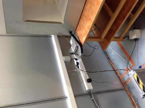
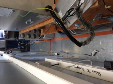
6 RAPPORT D'ESSAI / TEST REPORT N A1-R1-E Page : 6 / RADIATED EMISSION DATA 3.1. TEST CONDITIONS Date of test : July 24 th, 2013 Test performed by : A.MERLIN Atmospheric pressure : 1004mb Relative humidity : 41% Ambient temperature : 24 C 3.2. TEST SETUP The installation of EUT is identical for pre-characterization measurement in a 3 meters semi anechoic chamber and for measures on a 10 meters Open site. Configuration n 1


7 RAPPORT D'ESSAI / TEST REPORT N A1-R1-E Page : 7 / 59


8 RAPPORT D'ESSAI / TEST REPORT N A1-R1-E Page : 8 / 59 Configuration n 2


9 RAPPORT D'ESSAI / TEST REPORT N A1-R1-E Page : 9 / 59 Configuration n 3


10 RAPPORT D'ESSAI / TEST REPORT N A1-R1-E Page : 10 / 59 Configuration n 4 Radiated emission test setup
11 RAPPORT D'ESSAI / TEST REPORT N A1-R1-E Page : 11 / TEST EQUIPMENT LIST DESCRIPTION MANUFACTURER MODEL N LCIE Antenna Bi-log CHASE CBL6111A C Antenna Loop ELECTRO-METRICS EM-6879 C Antenna Bi-Log AH System SAS C Cable SUCOFLEX 106G A Cable - - A Cable OATS (Mast at 10m) UTIFLEX - A Cable - - A Cable OATS (Mast at 10m) UTIFLEX - A Cable - - A Semi-Anechoic chamber #1 SIEPEL - D Radiated emission comb generator BARDET - A OATS - - F Receiver 20Hz 8GHz ROHDE & SCHWARZ ESU8 A Thermo-hygrometer (PM2) OREGON BAR916HG-G B Thermo-hygrometer (C1) OREGON WMR 80 B Turntable / Mast controller (OATS) ETS Lindgren Model 2066 F Antenna mast (OATS) ETS Lindgren F Turntable (OATS) ETS Lindgren Model 2187 F Turntable chamber (Cage#1) MATURO Gmbh TT 2.0 SI F Antenna mast (Cage#1) MATURO Gmbh AM 4.0 F Turntable controller (Cage#1) MATURO Gmbh Control Unit F
12 RAPPORT D'ESSAI / TEST REPORT N A1-R1-E Page : 12 / DIVERGENCE, ADDITION OR SUPPRESSION ON THE TEST SPECIFICATION None 3.5. TEST SEQUENCE AND RESULTS Pre-characterization at 3 meters [9kHz-30MHz] A pre-scan of all the setup has been performed in a 3 meters semi anechoic chamber. The distance between EUT and antenna is 3 meters. For Pre-characterization, the loop antenna was rotated during the test for maximized the emission measurement. Measurement performed on 3 axis of EUT. Frequency band investigated is 9kHz to 30MHz. The pre-characterization graphs are obtained in PEAK detection. See graph for 9kHz-30MHz band: Configuration n 1 Emr#1 (See annex 1) See graph for 9kHz-30MHz band: Configuration n 2 Emr#4 (See annex 1) See graph for 9kHz-30MHz band: Configuration n 3 Emr#7 (See annex 1) See graph for 9kHz-30MHz band: Configuration n 4 Emr#10 (See annex 1) Pre-characterization [30MHz-1GHz] For frequency band 30MHz to 1GHz, a pre-scan of all the setup has been performed in a 3 meters semi anechoic chamber. The distance between EUT and antenna is 3 meters. Test is performed in horizontal (H) and vertical (V) polarization with a log-periodic antenna. The EUT is being rotated on 360 and on 3 axis during the measurement. The pre-characterization graphs are obtained in PEAK detection. See graphs for 30MHz-1GHz: H polarization Configuration n 1 Emr#2 (See annex 1) V polarization Configuration n 1 Emr#3 (See annex 1) H polarization Configuration n 2 Emr#5 (See annex 1) V polarization Configuration n 2 Emr#6 (See annex 1) H polarization Configuration n 3 Emr#8 (See annex 1) V polarization Configuration n 3 Emr#9 (See annex 1) H polarization Configuration n 4 Emr#11 (See annex 1) V polarization Configuration n 4 Emr#12 (See annex 1)
13 RAPPORT D'ESSAI / TEST REPORT N A1-R1-E Page : 13 / Characterization on 10 meters open site below 30 MHz The product has been tested according to ANSI C63.4 (2003), FCC part 15 subpart C. Radiated Emissions were measured on an open area test site. A description of the facility is on file with the FCC. The product has been tested at a distance of 10 meters from the antenna and compared to the FCC part 15 subpart C limits in the frequency range MHz MHz. Measurement bandwidth was 9kHz. Antenna height was 1m for both horizontal and vertical polarization. Antenna was rotated around its vertical axis. Continuous linear turntable azimuth search was performed with 360 degrees range. Measurement performed on 3 axis of EUT. A summary of the worst case emissions found in all test configurations and modes is shown on clauses 3.2. Same results with 4 configurations Frequency (MHz) QPeak Limit 30m Qpeak Qpeak (dbµv/m) Qpeak-Limit (Margin db) Turntable Angle (deg) Ant. Pol./ Angle (deg) Tot Corr (db) 13.56* * 1 : Measure have been done at 10m distance and corrected according to requirements of e) (M@30m = M@10m-19.1dB) Limits Sub clause Frequency (MHz) Field strength (µv/m) Measurement distance (m) dbµv/m dbµv/m dbµv/m 30 See chapter 5 of this test report for band edge measurements.
14 RAPPORT D'ESSAI / TEST REPORT N A1-R1-E Page : 14 / Characterization on 3 meters open site from 30MHz to 1GHz The product has been tested at a distance of 3 meters from the antenna and compared to the FCC part 15 subpart B limits and C limits. Measurement bandwidth was 120kHz from 30 MHz to 1GHz. Antenna height search was performed from 1m to 4m for both horizontal and vertical polarization. Continuous linear turntable azimuth search was performed with 360 degrees range. Measurement performed on 3 axis of EUT. A summary of the worst case emissions found in all test configurations and modes is shown on clause 3.2 Worst case final data result: Configuration n 1 No Frequency QPeak Limit Qpeak Qpeak-Limit Angle Hgt Tot Corr Pol (MHz) (dbµv/m) (dbµv/m) (Margin, db) (deg) (cm) (db) V V H V H V H H H V H V H H H V H V V H V Comments Configuration n 2 No Frequency QPeak Limit Qpeak Qpeak-Limit Angle Hgt Tot Corr Pol (MHz) (dbµv/m) (dbµv/m) (Margin, db) (deg) (cm) (db) V H H H H H V V V H H H H V H Comments
15 RAPPORT D'ESSAI / TEST REPORT N A1-R1-E Page : 15 / 59 Configuration n 3 No Frequency QPeak Limit Qpeak Qpeak-Limit Angle Hgt Tot Corr Pol (MHz) (dbµv/m) (dbµv/m) (Margin, db) (deg) (cm) (db) H V V H H H H V H H V V Comments Configuration n 4 No Frequency QPeak Limit Qpeak Qpeak-Limit Angle Hgt Tot Corr Pol (MHz) (dbµv/m) (dbµv/m) (Margin, db) (deg) (cm) (db) H H V V H H V H H V H H Comments RESULTS: PASS
16 RAPPORT D'ESSAI / TEST REPORT N A1-R1-E Page : 16 / FIELD STRENGTH CALCULATION The field strength is calculated by adding the Antenna Factor and Cable Factor, and subtracting the Amplifier Gain (if any) from the measured reading. The basic equation with a sample calculation is as follow: FS = RA + AF + CF AG Where FS = Field Strength RA = Receiver Amplitude AF = Antenna Factor CF = Cable Factor AG = Amplifier Gain Assume a receiver reading of 52.5dBµV is obtained. The antenna factor of 7.4 and a cable factor of 1.1 are added. The amplifier gain of 29dB is subtracted, giving a field strength of 32 dbµv/m. FS = = 32 dbµv/m The 32 dbµv/m value can be mathematically converted to its corresponding level in µv/m. Level in µv/m = Common Antilogarithm [(32dBµV/m)/20] = 39.8 µv/m.

17 RAPPORT D'ESSAI / TEST REPORT N A1-R1-E Page : 17 / FUNDAMENTAL FREQUENCY TOLERANCE (15.225E) 4.1. TEST CONDITIONS Date of test : July 24 th, 2013 Test performed by : A.MERLIN 4.1. TEMPERATURE AND VOLTAGE FLUCTUATION The frequency tolerance of the carrier signal shall be maintained within ±0.01% of the operating frequency when the temperature is varied from -20 C to +50 C at the nominal power voltage and the DC power voltage is varied from 17VCD to 27VDC of the rated supply voltage at 20 C. (Worst case) 4.2. TEST SETUP Temperature has been set at +20 C, 20 C and +50 C. Voltage is varied from 17VDC to 27VDC, worst case, Frequency of carrier: MHz Upper limit: MHz Lower limit: MHz The equipment (RF box) is set in a climatic chamber. Measure is performed on one channel of RF module.
18 RAPPORT D'ESSAI / TEST REPORT N A1-R1-E Page : 18 / TEST SEQUENCE AND RESULTS Voltage Temperature -30 C -20 C 20 C +50 C Mains voltage: 24VDC Frequency Drift (MHz) Carrier level (dbc) Mains voltage: 18VDC Frequency Drift (MHz) Carrier level (dbc) Mains voltage: 27VDC Frequency Drift (MHz) Carrier level (dbc) Frequency drift measured is 99 Hz when the temperature is varied from -30 C to +50 C and voltage is varied TEST EQUIPMENT LIST DESCRIPTION MANUFACTURER MODEL N LCIE Attenuator 14dB RADIALL - A Cable SMA - - A Climatic chamber BIA CLIMATIC CL 6-25 D Data Logger AGILENT 34970A A Data Logger card AGILENT 34970A A Frequency Counter HEWLETT PACKARD HP 5350B B Multimeter FLUKE 189 A Power supply DC AFX 0 A Receiver 9kHz - 6GHz ROHDE & SCHWARZ FSL6 A DIVERGENCE, ADDITION OR SUPPRESSION ON THE TEST SPECIFICATION None
19 RAPPORT D'ESSAI / TEST REPORT N A1-R1-E Page : 19 / BAND-EDGE COMPLIANCE TEST CONDITIONS Date of test : July 24 th, 2013 Test performed by : A.MERLIN Atmospheric pressure : 1004mb Relative humidity : 41% Ambient temperature : 24 C 5.2. TEST EQUIPMENT LIST DESCRIPTION MANUFACTURER MODEL N LCIE Antenna Loop ELECTRO-METRICS EM-6879 C Antenna Bi-Log AH System SAS C Cable - - A Cable - - A Semi-Anechoic chamber #1 SIEPEL - D Receiver 20Hz 8GHz ROHDE & SCHWARZ ESU8 A Thermo-hygrometer (PM2) OREGON BAR916HG-G B Thermo-hygrometer (C1) OREGON WMR 80 B Turntable chamber (Cage#1) MATURO Gmbh TT 2.0 SI F Antenna mast (Cage#1) MATURO Gmbh AM 4.0 F Turntable controller (Cage#1) MATURO Gmbh Control Unit F DIVERGENCE, ADDITION OR SUPPRESSION ON THE TEST SPECIFICATION None
20 RAPPORT D'ESSAI / TEST REPORT N A1-R1-E Page : 20 / FREQUENCY BAND MHZ Following plots show radiated emission level in the frequency band MHz with a RBW of 9kHz and a quasi-peak detector. The graphs are obtained with a measuring receiver ESU8.
21 RAPPORT D'ESSAI / TEST REPORT N A1-R1-E Page : 21 / OCCUPIED BANDWIDTH 6.1. CLIMATIC CONDITIONS Date of test : July 24 th, 2013 Test performed by : A.MERLIN Atmospheric pressure : 1004mb Relative humidity : 41% Ambient temperature : 24 C 6.2. TEST RESULTS Measured occupied bandwidth is 2.4 khz Measurement settings: RBW = 200Hz / Video BW = 500Hz / SPAN = 20kHz / PEAK / Maxhold / OBW function The occupied bandwidth is measured with OBW function of spectrum analyzer.
22 RAPPORT D'ESSAI / TEST REPORT N A1-R1-E Page : 22 / TEST EQUIPMENT LIST DESCRIPTION MANUFACTURER MODEL N LCIE Antenna Loop ELECTRO-METRICS EM-6879 C Antenna Bi-Log AH System SAS C Cable - - A Cable - - A Semi-Anechoic chamber #1 SIEPEL - D Receiver 20Hz 8GHz ROHDE & SCHWARZ ESU8 A Thermo-hygrometer (PM2) OREGON BAR916HG-G B Thermo-hygrometer (C1) OREGON WMR 80 B Turntable chamber (Cage#1) MATURO Gmbh TT 2.0 SI F Antenna mast (Cage#1) MATURO Gmbh AM 4.0 F Turntable controller (Cage#1) MATURO Gmbh Control Unit F DIVERGENCE, ADDITION OR SUPPRESSION ON THE TEST SPECIFICATION None


23 RAPPORT D'ESSAI / TEST REPORT N A1-R1-E Page : 23 / CONDUCTED EMISSION DATA 7.1. TEST CONDITIONS Date of test : July 23 rd, 2013 Test performed by : A.MERLIN Atmospheric pressure : 1000mb Relative humidity : 35% Ambient temperature : 25 C 7.2. SETUP FOR CONDUCTED EMISSIONS MEASUREMENT The product has been tested according to ANSI C63.4-(2003) and FCC Part 15 subpart B and C. The product has been tested with 120V/60Hz power line voltage and compared to the FCC Part 15 subpart B and C limits. Measurement bandwidth was 9kHz from 150kHz to 30MHz. Measurement is made with a Rohde & Schwarz ESU8 receiver in peak mode. This was followed by a Quasi-Peak, i.e. CISPR measurement for any strong signal. If the average limit is met when using a Quasi-Peak detector, the EUT shall be deemed to meet both limits and measurement with the average detector is unnecessary. The LISN (measure) is 50 / 50µH. The Peak data are shown on plots in annex 1. Quasi-Peak and Average measurements are detailed in a table with frequencies and levels measured. Interconnecting cables and equipment's were moved to position that maximized emission. A summary of the worst case emissions found in all test configurations and modes is shown on the following page. The EUT is placed on the ground reference plane, at 80cm from the LISN. The distance between the EUT and the vertical ground plane is 40cm. Auxiliaries are powered by another LISN. The cable has been shorted to 1meter length. The EUT is powered trough the LISN (measure). Configuration n 1


24 RAPPORT D'ESSAI / TEST REPORT N A1-R1-E Page : 24 / 59


25 RAPPORT D'ESSAI / TEST REPORT N A1-R1-E Page : 25 / 59


26 RAPPORT D'ESSAI / TEST REPORT N A1-R1-E Page : 26 / 59 Configuration n 2


27 RAPPORT D'ESSAI / TEST REPORT N A1-R1-E Page : 27 / 59 Configuration n 3


28 RAPPORT D'ESSAI / TEST REPORT N A1-R1-E Page : 28 / 59 Configuration n 4 Conducted emission test setup

29 RAPPORT D'ESSAI / TEST REPORT N A1-R1-E Page : 29 / 59 Dummy load 7.3. TEST EQUIPMENT LIST DESCRIPTION MANUFACTURER MODEL N LCIE Cable - - A Conducted emission comb generator BARDET - A LISN TELEMETER ELECTRONIC NNB-2/16Z C LISN RHODE & SCHWARZ ENV216 C Receiver 20Hz 8GHz ROHDE & SCHWARZ ESU8 A Thermo-hygrometer (PM2) OREGON BAR916HG-G B Transient limiter RHODE & SCHWARZ ESH3-Z2 A DIVERGENCE, ADDITION OR SUPPRESSION ON THE TEST SPECIFICATION None
30 RAPPORT D'ESSAI / TEST REPORT N A1-R1-E Page : 30 / TEST SEQUENCE AND RESULTS Measurements are performed on the phase (L1) and neutral (N) of power line voltage. A measurement is also performed with a 50Ω dummy load replacing the transmitter antenna in order to demonstrate that some 13.56MHz may be cross-coupled to AC line connection. Graphs are obtained in PEAK detection. Measures are also performed in Quasi-Peak and Average for any strong signal. Configuration n 1 Measure on L1: graph Emc#1 (see annex 1) Measure on N: graph Emc#2 (see annex 1) Measure on L1: graph Emc#3 With Dummy Load (see annex 1) Measure on N: graph Emc#4 With Dummy Load (see annex 1) Configuration n 2 Measure on L1: graph Emc#5 (see annex 1) Measure on N: graph Emc#6 (see annex 1) Measure on L1: graph Emc#7 With Dummy Load (see annex 1) Measure on N: graph Emc#8 With Dummy Load (see annex 1) Configuration n 3 Measure on L1: graph Emc#9 (see annex 1) Measure on N: graph Emc#10 (see annex 1) Measure on L1: graph Emc#11 With Dummy Load (see annex 1) Measure on N: graph Emc#12 With Dummy Load (see annex 1) Configuration n 4 Measure on L1: graph Emc#13 (see annex 1) Measure on N: graph Emc#14 (see annex 1) Measure on L1: graph Emc#15 With Dummy Load (see annex 1) Measure on N: graph Emc#16 With Dummy Load (see annex 1) RESULT: PASS
31 RAPPORT D'ESSAI / TEST REPORT N A1-R1-E Page : 31 / ANNEX 1 (GRAPHS) RADIATED EMISSIONS Graph name : Emr#1 Test configuration: Limit : FCC Part15C Class : - Tunnel + XP Power PARAMETERS Antenna polarization: 0 Legend: Azimuth : RBW : 200Hz / 9kHz Peak Measure VBW : 1kHz / 30kHz Frequency : 9kHz - 30MHz QPeak Limit@3m Frequency (MHz) Peak (dbµv/m)
32 RAPPORT D'ESSAI / TEST REPORT N A1-R1-E Page : 32 / 59 RADIATED EMISSIONS Graph name : Emr#2 Test configuration: Limit : FCC Part15C Class : Tunnel + XP Power PARAMETERS Antenna polarization: Horizontal Legend: Azimuth : RBW : 100kHz Peak Measure VBW : 300kHz Frequency : 30MHz - 1GHz QPeak Limit@3m Frequency (MHz) Peak (dbµv/m)
33 RAPPORT D'ESSAI / TEST REPORT N A1-R1-E Page : 33 / 59 RADIATED EMISSIONS Graph name : Emr#3 Test configuration: Limit : FCC Part15C Class : Tunnel + XP Power PARAMETERS Antenna polarization: Vertical Legend: Azimuth : RBW : 100kHz Peak Measure VBW : 300kHz Frequency : 30MHz - 1GHz QPeak Limit@3m Frequency (MHz) Peak (dbµv/m)
34 RAPPORT D'ESSAI / TEST REPORT N A1-R1-E Page : 34 / 59 RADIATED EMISSIONS Graph name : Emr#4 Test configuration: Limit : FCC Part15C Class : Tunnel + Traco + Filtre PARAMETERS Antenna polarization: 0 Legend: Azimuth : RBW : 200Hz / 9kHz Peak Measure VBW : 1kHz / 30kHz Frequency : 9kHz - 30MHz QPeak Limit@3m Frequency (MHz) Peak (dbµv/m)
35 RAPPORT D'ESSAI / TEST REPORT N A1-R1-E Page : 35 / 59 RADIATED EMISSIONS Graph name : Emr#5 Test configuration: Limit : FCC Part15C Class : Tunnel + Traco + Filtre PARAMETERS Antenna polarization: Horizontal Legend: Azimuth : RBW : 100kHz Peak Measure VBW : 300kHz Frequency : 30MHz - 1GHz QPeak Limit@3m Frequency (MHz) Peak (dbµv/m)
36 RAPPORT D'ESSAI / TEST REPORT N A1-R1-E Page : 36 / 59 RADIATED EMISSIONS Graph name : Emr#6 Test configuration: Limit : FCC Part15C Class : Tunnel + Traco + Filtre PARAMETERS Antenna polarization: Vertical Legend: Azimuth : RBW : 100kHz Peak Measure VBW : 300kHz Frequency : 30MHz - 1GHz QPeak Limit@3m Frequency (MHz) Peak (dbµv/m)
37 RAPPORT D'ESSAI / TEST REPORT N A1-R1-E Page : 37 / 59 RADIATED EMISSIONS Graph name : Emr#7 Test configuration: Limit : FCC Part15C Class : Tunnel + Schneider + Filtre PARAMETERS Antenna polarization: 0 Legend: Azimuth : RBW : 200Hz / 9kHz Peak Measure VBW : 1kHz / 30kHz Frequency : 9kHz - 30MHz QPeak Limit@3m Frequency (MHz) Peak (dbµv/m)
38 RAPPORT D'ESSAI / TEST REPORT N A1-R1-E Page : 38 / 59 RADIATED EMISSIONS Graph name : Emr#8 Test configuration: Limit : FCC Part15C Class : Tunnel + Schneider + Filtre PARAMETERS Antenna polarization: Horizontal Legend: Azimuth : RBW : 100kHz Peak Measure VBW : 300kHz Frequency : 30MHz - 1GHz QPeak Limit@3m Frequency (MHz) Peak (dbµv/m)
39 RAPPORT D'ESSAI / TEST REPORT N A1-R1-E Page : 39 / 59 RADIATED EMISSIONS Graph name : Emr#9 Test configuration: Limit : FCC Part15C Class : Tunnel + Schneider + Filtre PARAMETERS Antenna polarization: Vertical Legend: Azimuth : RBW : 100kHz Peak Measure VBW : 300kHz Frequency : 30MHz - 1GHz QPeak Limit@3m Frequency (MHz) Peak (dbµv/m)
40 RAPPORT D'ESSAI / TEST REPORT N A1-R1-E Page : 40 / 59 RADIATED EMISSIONS Graph name : Emr#10 Test configuration: Limit : FCC Part15C Class : - Tunnel + VPE + Filtre PARAMETERS Antenna polarization: 0 Legend: Azimuth : RBW : 200Hz / 9kHz Peak Measure VBW : 1kHz / 30kHz Frequency : 9kHz - 30MHz QPeak Limit@3m Frequency (MHz) Peak (dbµv/m)
41 RAPPORT D'ESSAI / TEST REPORT N A1-R1-E Page : 41 / 59 RADIATED EMISSIONS Graph name : Emr#11 Test configuration: Limit : FCC Part15C Class : - Tunnel + VPE + Filtre PARAMETERS Antenna polarization: Horizontal Legend: Azimuth : RBW : 100kHz Peak Measure VBW : 300kHz Frequency : 30MHz - 1GHz QPeak Limit@3m Frequency (MHz) Peak (dbµv/m)
42 RAPPORT D'ESSAI / TEST REPORT N A1-R1-E Page : 42 / 59 RADIATED EMISSIONS Graph name : Emr#12 Test configuration: Limit : FCC Part15C Class : - Tunnel + VPE + Filtre PARAMETERS Antenna polarization: Vertical Legend: Azimuth : RBW : 100kHz Peak Measure VBW : 300kHz Frequency : 30MHz - 1GHz QPeak Limit@3m Frequency (MHz) Peak (dbµv/m)
43 RAPPORT D'ESSAI / TEST REPORT N A1-R1-E Page : 43 / 59 CONDUCTED EMISSIONS Graph name : Emc#1 Test configuration: Limit : EN Tunnel - XP Power (P) Class : B PARAMETERS Voltage / Frequency : 110VAC / 60Hz Legend: Line : Phase RBW : 10kHz Peak Measure VBW : 30kHz Frequency : 150kHz- 30MHz QPeak Limit Average Measure Average Limit Frequency (MHz) Avg Lim Avg MesAvg - LimAvg QPeak Lim QPeak MesQP - LimQP * *carrier frequency, see dummy load test
44 RAPPORT D'ESSAI / TEST REPORT N A1-R1-E Page : 44 / 59 CONDUCTED EMISSIONS Graph name : Emc#2 Test configuration: Limit : EN Tunnel - XP Power (N) Class : B PARAMETERS Voltage / Frequency : 110VAC / 60Hz Legend: Line : Neutral RBW : 10kHz Peak Measure VBW : 30kHz Frequency : 150kHz- 30MHz QPeak Limit Average Measure Average Limit Frequency (MHz) Avg Lim Avg MesAvg - LimAvg QPeak Lim QPeak MesQP - LimQP * *carrier frequency, see dummy load test
45 RAPPORT D'ESSAI / TEST REPORT N A1-R1-E Page : 45 / 59 CONDUCTED EMISSIONS Graph name : Emc#3 Test configuration: Limit : EN Tunnel - XP Power - Dummy load (P) Class : B PARAMETERS Voltage / Frequency : 110VAC / 60Hz Legend: Line : Phase RBW : 10kHz Peak Measure VBW : 30kHz Frequency : 150kHz- 30MHz QPeak Limit Average Measure Average Limit Frequency (MHz) Avg Lim Avg MesAvg - LimAvg QPeak Lim QPeak MesQP - LimQP
46 RAPPORT D'ESSAI / TEST REPORT N A1-R1-E Page : 46 / 59 CONDUCTED EMISSIONS Graph name : Emc#4 Test configuration: Limit : EN Tunnel - XP Power - Dummy load (N) Class : B PARAMETERS Voltage / Frequency : 110VAC / 60Hz Legend: Line : Neutral RBW : 10kHz Peak Measure VBW : 30kHz Frequency : 150kHz- 30MHz QPeak Limit Average Measure Average Limit Frequency (MHz) Avg Lim Avg MesAvg - LimAvg QPeak Lim QPeak MesQP - LimQP
47 RAPPORT D'ESSAI / TEST REPORT N A1-R1-E Page : 47 / 59 CONDUCTED EMISSIONS Graph name : Emc#5 Test configuration: Limit : EN Tunnel - Traco (P) Class : B PARAMETERS Voltage / Frequency : 110VAC / 60Hz Legend: Line : Phase RBW : 10kHz Peak Measure VBW : 30kHz Frequency : 150kHz- 30MHz QPeak Limit Average Measure Average Limit Frequency (MHz) Avg Lim Avg MesAvg - LimAvg QPeak Lim QPeak MesQP - LimQP * *carrier frequency, see dummy load test
 Avg Lim Avg MesAvg - LimAvg QPeak Lim")
48 RAPPORT D'ESSAI / TEST REPORT N A1-R1-E Page : 48 / 59 CONDUCTED EMISSIONS Graph name : Emc#6 Test configuration: Limit : EN Tunnel - Traco (N) Class : B PARAMETERS Voltage / Frequency : 110VAC / 60Hz Legend: Line : Neutral RBW : 10kHz Peak Measure VBW : 30kHz Frequency : 150kHz- 30MHz QPeak Limit Average Measure Average Limit Frequency (MHz) Avg Lim Avg MesAvg - LimAvg QPeak Lim QPeak MesQP - LimQP * *carrier frequency, see dummy load test
49 RAPPORT D'ESSAI / TEST REPORT N A1-R1-E Page : 49 / 59 CONDUCTED EMISSIONS Graph name : Emc#7 Test configuration: Limit : EN Tunnel - Traco - Dummy load (P) Class : B PARAMETERS Voltage / Frequency : 110VAC / 60Hz Legend: Line : Phase RBW : 10kHz Peak Measure VBW : 30kHz Frequency : 150kHz- 30MHz QPeak Limit Average Measure Average Limit Frequency (MHz) Avg Lim Avg MesAvg - LimAvg QPeak Lim QPeak MesQP - LimQP
50 RAPPORT D'ESSAI / TEST REPORT N A1-R1-E Page : 50 / 59 CONDUCTED EMISSIONS Graph name : Emc#8 Test configuration: Limit : EN Tunnel - Traco - Dummy load (N) Class : B PARAMETERS Voltage / Frequency : 110VAC / 60Hz Legend: Line : Neutral RBW : 10kHz Peak Measure VBW : 30kHz Frequency : 150kHz- 30MHz QPeak Limit Average Measure Average Limit Frequency (MHz) Avg Lim Avg MesAvg - LimAvg QPeak Lim QPeak MesQP - LimQP
51 RAPPORT D'ESSAI / TEST REPORT N A1-R1-E Page : 51 / 59 CONDUCTED EMISSIONS Graph name : Emc#9 Test configuration: Limit : EN Tunnel - Schneider + Filtre (P) Class : B PARAMETERS Voltage / Frequency : 230VAC / 50Hz Legend: Line : Phase 1 RBW : 10kHz Peak Measure VBW : 30kHz Frequency : 150kHz- 30MHz QPeak Limit Average Measure Average Limit Frequency (MHz) Mes.Avg Lim.Avg Mes.Avg- Lim.Avg (db) Mes.Q-Peak Lim.Q-Peak Mes.Q-Peak- Lim.Q-Peak (db)
52 RAPPORT D'ESSAI / TEST REPORT N A1-R1-E Page : 52 / 59 CONDUCTED EMISSIONS Graph name : Emc#10 Test configuration: Limit : EN Tunnel - Schneider + Filtre (N) Class : B PARAMETERS Voltage / Frequency : 230VAC / 50Hz Legend: Line : Neutre RBW : 10kHz Peak Measure VBW : 30kHz Frequency : 150kHz- 30MHz QPeak Limit Average Measure Average Limit Frequency (MHz) Mes.Avg Lim.Avg Mes.Avg- Lim.Avg (db) Mes.Q-Peak Lim.Q-Peak Mes.Q-Peak- Lim.Q-Peak (db)
53 RAPPORT D'ESSAI / TEST REPORT N A1-R1-E Page : 53 / 59 CONDUCTED EMISSIONS Graph name : Emc#10 Test configuration: Limit : EN Tunnel - Schneider + Filtre - Dummy load (P) Class : B PARAMETERS Voltage / Frequency : 230VAC / 50Hz Legend: Line : Phase 1 RBW : 10kHz Peak Measure VBW : 30kHz Frequency : 150kHz- 30MHz QPeak Limit Average Measure Average Limit Frequency (MHz) Mes.Avg Lim.Avg Mes.Avg- Lim.Avg (db) Mes.Q-Peak Lim.Q-Peak Mes.Q-Peak- Lim.Q-Peak (db)
54 RAPPORT D'ESSAI / TEST REPORT N A1-R1-E Page : 54 / 59 CONDUCTED EMISSIONS Graph name : Emc#11 Test configuration: Limit : EN Tunnel - Schneider + Filtre - Dummy load (N) Class : B PARAMETERS Voltage / Frequency : 230VAC / 50Hz Legend: Line : Neutre RBW : 10kHz Peak Measure VBW : 30kHz Frequency : 150kHz- 30MHz QPeak Limit Average Measure Average Limit Frequency (MHz) Mes.Avg Lim.Avg Mes.Avg- Lim.Avg (db) Mes.Q-Peak Lim.Q-Peak Mes.Q-Peak- Lim.Q-Peak (db)
55 RAPPORT D'ESSAI / TEST REPORT N A1-R1-E Page : 55 / 59 CONDUCTED EMISSIONS Graph name : Emc#15 Test configuration: Limit : EN Tunnel - VPE + Filtre - Dummy load (P) Class : B PARAMETERS Voltage / Frequency : 230VAC / 50Hz Legend: Line : Phase 1 RBW : 10kHz Peak Measure VBW : 30kHz Frequency : 150kHz- 30MHz QPeak Limit Average Measure Average Limit Frequency (MHz) Mes.Avg Lim.Avg Mes.Avg- Lim.Avg (db) Mes.Q-Peak Lim.Q-Peak Mes.Q-Peak- Lim.Q-Peak (db)
56 RAPPORT D'ESSAI / TEST REPORT N A1-R1-E Page : 56 / 59 CONDUCTED EMISSIONS Graph name : Emc#16 Test configuration: Limit : EN Tunnel - VPE + Filtre - Dummy load (N) Class : B PARAMETERS Voltage / Frequency : 230VAC / 50Hz Legend: Line : Neutre RBW : 10kHz Peak Measure VBW : 30kHz Frequency : 150kHz- 30MHz QPeak Limit Average Measure Average Limit Frequency (MHz) Mes.Avg Lim.Avg Mes.Avg- Lim.Avg (db) Mes.Q-Peak Lim.Q-Peak Mes.Q-Peak- Lim.Q-Peak (db)
57 RAPPORT D'ESSAI / TEST REPORT N A1-R1-E Page : 57 / 59 CONDUCTED EMISSIONS Graph name : Emc#13 Test configuration: Limit : EN Tunnel - VPE + Filtre (P) Class : B PARAMETERS Voltage / Frequency : 230VAC / 50Hz Legend: Line : Phase 1 RBW : 10kHz Peak Measure VBW : 30kHz Frequency : 150kHz- 30MHz QPeak Limit Average Measure Average Limit Frequency (MHz) Mes.Avg Lim.Avg Mes.Avg- Lim.Avg (db) Mes.Q-Peak Lim.Q-Peak Mes.Q-Peak- Lim.Q-Peak (db)
58 RAPPORT D'ESSAI / TEST REPORT N A1-R1-E Page : 58 / 59 CONDUCTED EMISSIONS Graph name : Emc#14 Test configuration: Limit : EN Tunnel - VPE + Filtre (N) Class : B PARAMETERS Voltage / Frequency : 230VAC / 50Hz Legend: Line : Neutre RBW : 10kHz Peak Measure VBW : 30kHz Frequency : 150kHz- 30MHz QPeak Limit Average Measure Average Limit Frequency (MHz) Mes.Avg Lim.Avg Mes.Avg- Lim.Avg (db) Mes.Q-Peak Lim.Q-Peak Mes.Q-Peak- Lim.Q-Peak (db)
59 RAPPORT D'ESSAI / TEST REPORT N A1-R1-E Page : 59 / UNCERTAINTIES CHART Type de mesure / Kind of measurement Incertitude élargie laboratoire / Wide uncertainty laboratory (k=2) x Incertitude limite du CISPR / CISPR uncertainty limit y Mesure des perturbations conduites en tension sur le réseau d énergie 3.57 db 3.6 db Measurement of conducted disturbances in voltage on the power port Mesure des perturbations conduites en tension sur le réseau de télécommunication A l étude / 3.28 db Measurement of conducted disturbances in voltage on the telecommunication port. Under consid. Mesure des perturbations discontinues conduites en tension 3.47 db 3.6 db Measurement of discontinuous conducted disturbances in voltage Mesure des perturbations conduites en courant A l étude / 2.90 db Measurement of conducted disturbances in current Under consid. Mesure du champ électrique rayonné sur le site en espace libre de Moirans 5.07 db 5.2 db Measurement of radiated electric field on the Moirans open area test site Les valeurs d incertitudes calculées du laboratoire étant inférieures aux valeurs d incertitudes limites établies par la norme, la conformité de l échantillon est établie directement par les Peakx limites applicables. / The uncertainty values calculated by the laboratory are lower than limit uncertainty values defined by the standard. The conformity of the sample is directly established by the applicable limits values.
Rapport d essai / Test report
 Rapport d essai / Test report N 9635-A1-R2-E JDE : 15566 DELIVRE A / ISSUED TO Objet / Subject : TAGSYS RFID 785 Voie Antiope Athélia III 136 LA CIOTAT - FRANCE : Essais de compatibilité électromagnétique
Rapport d essai / Test report
 Rapport d essai / Test report N 249987-R2-E JDE : 110606 DELIVRE A / ISSUED TO Objet / Subject : INGENICO 9 Avenue de la Gare Rovaltain TGV - BP 25156 26958 VALENCE Cedex 9 : Essais de compatibilité électromagnétique
Rapport d essai / Test report
 Rapport d essai / Test report N 201001-5974CR-R1-E JDE : 99157 DELIVRE A / ISSUED TO Objet / Subject : TAGSYS S.A. 180, Chemin de Saint Lambert 13821 LA PENNE SUR HUVEAUNE FRANCE : Essais de compatibilité
Rapport d essai / Test report
 Rapport d essai / Test report N 115578-R2-E JDE : 1626 Portée disponible sur www.cofrac.fr Laboratoire d essai accrédité N 1-1633 DELIVRE A / ISSUED TO Objet / Subject : INGENICO Rue Claude Chappe B.P.
Rapport d essai / Test report
 Etablissement de Voiron Z.I. des Blanchisseries 38500 Voiron Siret 408 363 174 00090 Tél. : +33 4 76 65 09 08 Fax : +33 4 76 35 36 00 Labo.voiron@lcie.fr Rapport d essai / Test report N 200708-4002C-R1-E
Rapport d essai / Test report
 Etablissement de Voiron Z.I. des Blanchisseries 38500 Voiron Siret 408 363 174 00090 Tél. : +33 4 76 65 09 08 Fax : +33 4 76 35 36 00 Labo.voiron@lcie.fr Rapport d essai / Test report N 200802-4315CR-A1-R2-E
N : R2-E JDE :
 TEST REPORT N : 821760-R2-E JDE : 133546 Subject Electromagnetic compatibility and Radio spectrum Matters (ERM) tests according to standards: EN 50364 (2010) EN 62369-1 (2009) Issued to Apparatus under
Quality Auditing Institute # Schoolhouse Street, Coquitlam, BC, V3K 4X9, Canada. ISO Accreditation:
 CANADA: 16-211 Schoolhouse Street Coquitlam, British Columbia Canada V3K 4X9 ELECTROMAGNETIC COMPATIBILITY TEST REPORT TO CFR 47 FCC Part 15, Subpart C, Section 15.225 Industry Canada RSS 210, Issue 8
DATES OF TESTS: From 03/10/2014 to 20/10/2014 and 25/02/2015. Open area test site in Aunainville (28) - FRANCE. Page 2 out of 54
 - FRANCE. Page 2 out of 54") TEST CERTIFICATION FOR: FCC Certification NAME OF THE EQUIPMENT UNDER TEST: Serial number: Wireless conference access point Type: CONFIDEA WCAP G3 1440077150000C1 Reference / model (P/N): 71.98.0033 V
TEST CERTIFICATION FOR: FCC Certification NAME OF THE EQUIPMENT UNDER TEST: Serial number: Wireless conference access point Type: CONFIDEA WCAP G3 1440077150000C1 Reference / model (P/N): 71.98.0033 V
RF test report AU01+W02
 Customer: Kehlbergstrasse 109 8054 Graz Austria Tel.: +43 664 415 6260 RF test report 170186-AU01+W02 The test result refers exclusively to the tested model. This test report may not be copied or published
TEST REPORT. For RFID READER/WRITER. In conformity with. FCC CFR 47 Part15 Subpart C
 TEST REPORT For RFID READER/WRITER In conformity with FCC CFR 47 Part15 Subpart C Model: TR3XM-SD01 / TR3XM-SU01 / TR3XM-SN01 FCC ID: MK4TR3XM-SX01 Test Item: RFID READER/WRITER Report No: RY1203Z12R1
HID GLOBAL CORPORATION
 HID GLOBAL CORPORATION RFID READER, OPERATING ON 125 KHZ AND 13.56 MHZ Model: ERP40C 12 January 2010 Report No.: SL09050401-HID-011_ERP40C (15.225 & RSS-210) (This report supersedes None)) Modifications
TEST REPORT N B Page 2
 TEST REPORT N 120636-641067B Page 2 TABLE OF CONTENTS 1 GENERAL 1.1 Summary of test results Page 3 1.2 References Page 3 1.3 Equipment under test specification Page 4 2 TEST RESULTS 2.1 Power line conducted
HID GLOBAL CORPORATION
 HID GLOBAL CORPORATION RFID READER, OPERATING ON 125 KHZ AND 13.56 MHZ Model: RMP40C, RM40C April 26th 2010 Report No.: SL10040902-HID-006(FCC,IC)-RMP40C (This report supersedes None) Modifications made
Chapter I - Federal Communications Commission Subchapter A - General Part 15 - Radio Frequency Devices Subpart C - Intentional Radiators
 www.nemko.com Report Reference ID 167484-1TRFWL Test specification Title 47 - Telecommunication Chapter I - Federal Communications Commission Subchapter A - General Part 15 - Radio Frequency Devices Subpart
Nemko Canada Inc., 303 River Road, R.R. 5, Ottawa, Ontario, Canada, K1V 1H2
 www.nemko.com Nemko Canada Inc., 303 River Road, R.R. 5, Ottawa, Ontario, Canada, K1V 1H2 Report Number: Product Marketing Name: 123766-1TRFEMC Paycheck 4 Thermal Ticket Printer Test Specification: FCC
To «Test_Standards» Test of: Radwin Ltd. Outdoor Subscriber Radio Unit. To: FCC CFR 47 Part 15B; ICES-003 Issue 6: 2016
 TEST REPORT ADDENDUM Part 15B & ICES-003 FROM To «Test_Standards» Test of: FCC CFR 47 Part 15B; ICES-003 Issue 6: 2016 Test Report Serial No.: Issue 13 th July 2016 Master Document Number RDWN41 U5 _Master
RADIO TEST REPORT. For MODEL NO FCC ID: C3K1703 IC ID: 3048A Test Report No. R-TR190-FCCIC-UNII-1 Issue Date: 14 September 2015
 RADIO TEST REPORT For MODEL NO. 1703 FCC ID: C3K1703 IC ID: 3048A-1703 Test Report No. R-TR190-FCCIC-UNII-1 Issue Date: 14 September 2015 FCC CFR47 Part 15 Subpart E Industry Canada RSS-247 Issue 1 Prepared
FCC Certification Test Report for the MEI Cashflow RFID Reader Base FCC ID: QP8EASITRAXRB
 for the FCC ID: QP8EASITRAXRB WLL JOB# 9915 September 21, 2007 Prepared for: 1301 Wilson Drive West Chester, PA 19380 Prepared By: Washington Laboratories, Ltd. 7560 Lindbergh Drive Gaithersburg, Maryland
FCC & RSS-216 (Class II Permissive Change) Wireless Power Transfer Report. for A Acer Incorporated
 Wireless Power Transfer Report. for A Acer Incorporated") Page 1 of 17 FCC 15.209 & RSS-216 (Class II Permissive Change) Wireless Power Transfer Report for A Acer Incorporated 8F., No.88, Sec. 1, Xintai 5th Rd., Xizhi, New Taipei City 22181, Taiwan (R.O.C) Product
Page 1 of 17 FCC 15.209 & RSS-216 (Class II Permissive Change) Wireless Power Transfer Report for A Acer Incorporated 8F., No.88, Sec. 1, Xintai 5th Rd., Xizhi, New Taipei City 22181, Taiwan (R.O.C) Product
REVISION HISTORY. The revision history for this document is shown in table. HCT-EM-1801-FC037 January 22, 2018 Initial Release
 REVISION HISTORY The revision history for this document is shown in table. Version Issue Date Description HCT-EM-1801-FC037 January 22, 2018 Initial Release HCT-EM-1801-FC037-R1 January 26, 2018 Revision
FCC Radio Test Report. Orpak Systems Ltd.
 DATE: 20 December 2015 I.T.L. (PRODUCT TESTING) LTD. FCC Radio Test Report for Orpak Systems Ltd. Equipment under test: Fuel Pump Nozzle Reader NNR EXTRA LARGE+SWITCH; NNR EXTRA LARGE* *See customer s
FCC CFR47 PART 15 SUBPART C INDUSTRY CANADA RSS-247 ISSUE 1 BLUETOOTH LOW ENERGY CERTIFICATION TEST REPORT FOR
 FCC CFR47 PART 15 SUBPART C INDUSTRY CANADA RSS-247 ISSUE 1 BLUETOOTH LOW ENERGY CERTIFICATION TEST REPORT FOR WLAN 2X2 MIMO 802.11a/b/g/n/ac with BLUETOOTH MODEL NUMBER: P2180 REPORT NUMBER: 15U21878-E2V1
FCC PART 15, CLASS B MEASUREMENT AND TEST REPORT. NanJing JingZe Lighting Technology Co.,Ltd
 FCC PART 15, CLASS B MEASUREMENT AND TEST REPORT For NanJing JingZe Lighting Technology Co.,Ltd No. 30, Hengfa Rd., National Economic Technological Development Zone, Nanjing, Jiangsu, China Tested Model:
F2 Labs Peters Road Middlefield, Ohio United States of America
 1674 Peters Road Middlefield, Ohio 4462 United States of America www.f2labs.com CERTIFICATION TEST REPORT Manufacturer: Applicant: Product Description: Libra Industries, Inc. 777 Division Drive Mentor,
Measurement of RF Emissions from a Caterpillar Inc. MSS3s RF ID Key Fob
 Measurement of RF Emissions from a Caterpillar Inc. MSS3s RF ID Key Fob For Caterpillar Inc. 330 S.W. Adams Street Peoria, IL 61630 P.O. Number JBL 11260 Date Tested May 11, 2016 Test Personnel Mark Longinotti
TEST REPORT CONCERNING THE COMPLIANCE OF PART 15 JBP
 Testing and certification of electronic and electric appliances, systems, installations and telecommunication systems TEST REPORT CONCERNING THE COMPLIANCE OF PART 15 JBP Class B Computing Device Peripheral,
FCC 47 CFR PART 15 SUBPART C INDUSTRY CANADA RSS-210 ISSUE 8 BLUETOOTH LOW ENERGY CERTIFICATION TEST REPORT FOR. 2.4GHz LE MODULE MODEL NUMBER: RN4020
 FCC 47 CFR PART 15 SUBPART C INDUSTRY CANADA RSS-210 ISSUE 8 BLUETOOTH LOW ENERGY CERTIFICATION TEST REPORT FOR 2.4GHz LE MODULE MODEL NUMBER: RN4020 REPORT NUMBER: 14U17191-1 ISSUE DATE: MARCH 21, 2014
Title: Test on 5.8 GHz Band Outdoor WiFi (802.11b/g) Wireless Base Station
 Wireless Base Station") Page 20 of 51 Pages 7.5. Conducted spurious emission 7.5.1. Requirements: Clause 15.247(d). In any 100 khz bandwidth outside the frequency band in which the spread spectrum or digitally modulated intentional
Page 20 of 51 Pages 7.5. Conducted spurious emission 7.5.1. Requirements: Clause 15.247(d). In any 100 khz bandwidth outside the frequency band in which the spread spectrum or digitally modulated intentional
FCC PART & IC RSS GHz FHSS TEST REPORT
 FCC PART 15.247 & IC RSS-247 2.4 GHz FHSS TEST REPORT 849 NW State Road 45 Newberry, FL 32669 USA Ph.: 888.472.2424 or 352.472.5500 Fax: 352.472.2030 Email: info@timcoengr.com Website: www.timcoengr.com
TEST REPORT. Report Number: MIN-001 Rev 1.1 Project Number: G Testing performed on the 2102 IPG
 TEST REPORT Report Number: 100511823MIN-001 Rev 1.1 Project Number: G100511823 Testing performed on the 2102 IPG FCC ID: SVHBAROSTIMIPG1 Industry Canada ID: 9464A-IPG210A to 47 CFR Part 95 Subpart I:2013
FCC Part 15C Compliance Test Report
 Test Report no.: FCC15CNFC_RM-1045_19.docx Date of Report: 07-May-2014 Number of pages: 15 Customer s Tia Melava Contact person: Testing laboratory: FIN-33720 TAMPERE, FINLAND Customer: Nokia Corporation
TEST REPORT FROM RFI GLOBAL SERVICES LTD
 TEST REPORT FROM RFI GLOBAL SERVICES LTD Test of: Ingenico France, IWL252-01T1535A To: 47CFR15.107, 47CFR15.109 and RSS-GEN Issue 3 December 2010 Test Report Serial No: RFI-EMC-RP82173JD02A V2.0 Version
FCC Certification Test Report For the Mars Electronics (MEI) easitrax FCC ID: QP8EASITRAX
 easitrax FCC ID: QP8EASITRAX") For the FCC ID: QP8EASITRAX WLL JOB# 9554 April 19, 2007 Prepared for: 1301 Wilson Drive West Chester, PA 19380 Prepared By: Washington Laboratories, Ltd. 7560 Lindbergh Drive Gaithersburg, Maryland 20879
For the FCC ID: QP8EASITRAX WLL JOB# 9554 April 19, 2007 Prepared for: 1301 Wilson Drive West Chester, PA 19380 Prepared By: Washington Laboratories, Ltd. 7560 Lindbergh Drive Gaithersburg, Maryland 20879
RF Emissions Test Report To Determine Compliance With: FCC, Part 15 Rules and Regulations
 RF Emissions Test Report To Determine Compliance With: FCC, Part 15 Rules and Regulations Model numbers: HT130022 Rev. B. December 17, 2002 Manufacturer: HQ, Inc. 210 9th Steet Drive Palmetto, FL 34221
RF test report AU02+W01
 Customer: Zeppelinstraße 11 82178 Puchheim Tel.: +49 89 5529961-0 Fax: +49 89 5529961-129 RF test report 170761-AU02+W01 The test result refers exclusively to the tested model. This test report may not
FCC DoC TEST REPORT To: PARTICLE INDUSTRIES, INC To: - Attn: Eric Attn: - Address: 1400 Tennessee St, #4 San Francisco, CA Address: -
 FCC DoC TEST REPORT To: PARTICLE INDUSTRIES, INC To: - Attn: Eric Attn: - Address: 1400 Tennessee St, #4 San Francisco, CA Address: - 94107 Fax: -- Fax: - E-mail: -- E-mail: - Folder No.: BVCZ16FE005ETHS-B
Test Report: 5R Champlain Street Dieppe, New Brunswick Canada E1A 1P6. Model Number: Verification
 Test Report: 5R46150.1 Applicant: Equipment Under Test: Model Number: In Accordance With: Tested By: Nanoptix Inc. 699 Champlain Street Dieppe, New Brunswick E1A 1P6 Spill Proof Cuts SPC FCC 47 CFR Part
L.S. Compliance, Inc. W66 N220 Commerce Court Cedarburg, WI
 L.S. Compliance, Inc. W66 N220 Commerce Court Cedarburg, WI 53012 262-375-4400 COMPLIANCE TESTING OF: Quartex Synchronization Transmitter Model FM-72 PREPARED FOR: Quartex, Division of Primex, Inc. 965
Page 1 of 20 No.: HM TEST REPORT FCC PART 15 SUBPART C CERTIFICATION REPORT FOR LOW POWER TRANSMITTER. TEST REPORT No.
 Page 1 of 20 FCC PART 15 SUBPART C CERTIFICATION REPORT FOR LOW POWER TRANSMITTER Equipment Under Test [EUT]: Model Number: Applicant: FCC ID : Radio Controlled Tank FH002 Zhongshan Fu Hai Electronics
f02 January 11, TÜV Rheinland Nederland B.V. P.O. Box AA Leek (NL) Eiberkamp VT Leek (NL)
 Eiberkamp VT Leek (NL)") Testing and certification of electronic and electric appliances, systems, installations and telecommunication systems TEST REPORT CONCERNING THE COMPLIANCE OF AN INTEL WIRELESS GIGABIT 11000, MODEL 11000D2W,
Testing and certification of electronic and electric appliances, systems, installations and telecommunication systems TEST REPORT CONCERNING THE COMPLIANCE OF AN INTEL WIRELESS GIGABIT 11000, MODEL 11000D2W,
TEST REPORT To: - ABO ELECTRONICS (SHENZHEN) CO., LTD Block B3, Haocheng Industrial Park, Hexiu West Rd, Heping Village, Fuyong, Baoan, Shenzhen
 CO., LTD Block B3, Haocheng Industrial Park, Hexiu West Rd, Heping Village, Fuyong, Baoan, Shenzhen") To: TEST REPORT No.: (5216)033-0360(A) PARTICLE INDUSTRIES, INC TEST REPORT To: - Attn: Eric Attn: - Address: 1400 Tennessee St, #4 San Francisco, CA Address: - 94107 Fax: -- Fax: - E-mail: -- E-mail:
To: TEST REPORT No.: (5216)033-0360(A) PARTICLE INDUSTRIES, INC TEST REPORT To: - Attn: Eric Attn: - Address: 1400 Tennessee St, #4 San Francisco, CA Address: - 94107 Fax: -- Fax: - E-mail: -- E-mail:
FCC Verification TEST REPORT
 FCC Verification TEST REPORT Product: 5 in 1 Environment Meter Model no.: ET-965 Trade Mark: N/A Report No.: TCT140915E005 Issued Date: Sep. 22, 2014 Issued for: Shenzhen Flus Technology Co., Ltd 3rd Floor,
TEST REPORT To: - ABO ELECTRONICS (SHENZHEN) CO., LTD Block B3, Haocheng Industrial Park, Hexiu West Rd, Heping Village, Fuyong, Baoan, Shenzhen
 CO., LTD Block B3, Haocheng Industrial Park, Hexiu West Rd, Heping Village, Fuyong, Baoan, Shenzhen") To: TEST REPORT No.: (5216)033-0357(A) PARTICLE INDUSTRIES, INC TEST REPORT To: - Attn: Eric Attn: - Address: 1400 Tennessee St, #4 San Francisco, CA Address: - 94107 Fax: -- Fax: - E-mail: -- E-mail:
To: TEST REPORT No.: (5216)033-0357(A) PARTICLE INDUSTRIES, INC TEST REPORT To: - Attn: Eric Attn: - Address: 1400 Tennessee St, #4 San Francisco, CA Address: - 94107 Fax: -- Fax: - E-mail: -- E-mail:
Advanced Compliance Solutions, Inc FAU Blvd, Suite 310 Boca Raton, Florida (561)
") 2129.01 Advanced Compliance Solutions, Inc. 3998 FAU Blvd, Suite 310 Boca Raton, Florida 33431 (561) 961-5585 Technical Report No. 09-2067a-2 EMI Evaluation of the AMM Marketing, LLC s E-Pulse UH 900,
2129.01 Advanced Compliance Solutions, Inc. 3998 FAU Blvd, Suite 310 Boca Raton, Florida 33431 (561) 961-5585 Technical Report No. 09-2067a-2 EMI Evaluation of the AMM Marketing, LLC s E-Pulse UH 900,
Page 1 of 51 Report No.: T TEST REPORT FCC ID: 2AGJ5WAP-30. In Accordance with: FCC PART 15, SUBPART C : 2015 (Section 15.
 Page 1 of 51 Report No.: T1851663 01 TEST REPORT FCC ID: 2AGJ5WAP-30 Applicant Address : Gonsin Conference Equipment Co., Ltd : No.401-406,Block C, Idea Industry Park, No.41 Fengxiang Road, Shunde, Foshan,
TRANSMITTER MODEL: KAS-2030M
 Page 1 of 16 FCC PART 15, SUBPART B and C TEST REPORT for TRANSMITTER MODEL: KAS-2030M Prepared for WILDLIFE TECHNOLOGIES 115 WOLCOTT STREET MANCHESTER, NEW HAMPSHIRE 03103 Prepared by: KYLE FUJIMOTO Approved
FCC TEST REPORT. Table of Contents. FCC Measurement Report
 Table of Contents FCC Measurement Report 1. Introduction 2. Product Information 3. Description of Tests 4. Test Condition 5. Test Results 5.1 Summary of Test Results 5.2 Radiated Emissions Measurement
Test Report. Prepared for: Becker Avionics, Inc. Model: TG Description: Aeronautical basestation radio used for emergencies
 Test Report Prepared for: Becker Avionics, Inc Model: TG660-50 Description: Aeronautical basestation radio used for emergencies Serial Number: 10001, 10002 FCC ID: 2AHX9TG660 To FCC Part 87 Date of Issue:
FCC 47 CFR PART 15 SUBPART C CERTIFICATION TEST REPORT FOR. Bluetooth Remote Control for Video Set Top Box MODEL NUMBER: IPRC1000 FCC ID: 2ABTE-L3YJC9
 FCC 47 CFR PART 15 SUBPART C CERTIFICATION TEST REPORT FOR Bluetooth Remote Control for Video Set Top Box MODEL NUMBER: IPRC1000 REPORT NUMBER: 15U22448-E1V4 ISSUE DATE: 3/7/2016 Prepared for Verizon Online
T A B L E O F C O N T E N T S DESCRIPTION PAGE
 TABLE OF CONTENTS DESCRIPTION PAGE 1. CERTIFICATION... 3 2. SUMMARY OF TEST RESULTS... 4 3. GENERAL INFORMATION... 5 3.1 PRODUCTION DESCRIPTION... 5 3.2 TEST MODES & EUT COMPONENTS DESCRIPTION... 5 3.3
EMI T E S T R E P O R T
 EMI T E S T R E P O R T - FCC Part 15B - Test Report No. : T38935-00-02TK 27. November 2014 Date of issue Type / Model Name : One Touch Select Plus Flex Product Description : Blood glucose meter with Bluetooth
DELTA Test Report. Radio parameter test of Aperio radio in Server lock KS PA2. Performed for ASSA AB
 DELTA Test Report TEST REPORT issued by an Accredited Testing Laboratory TEST Reg. no. 19 Radio parameter test of Aperio radio in Server lock KS100-640-PA2 Performed for ASSA AB REC-E704276_4 Rev. A Project
Compliance Engineering Ireland Ltd
 Page 1 of 27 Compliance Engineering Ireland Ltd RAYSTOWN, RATOATH ROAD, ASHBOURNE, CO. MEATH, IRELAND Tel: +353 1 8256722 Fax: +353 1 8256733 Project Number: 10E2475-5 Prepared for: Biancamed Ltd By Compliance
FCC TEST REPORT. Table of Contents. Report no. ETLE , Page 2 of 21
 Table of Contents FCC Measurement Report 1. Introduction 2. Product Information 3. Description of Tests 4. Test Condition 5. Test Results 5.1 Summary of Test Results 5.2 Conducted Emissions Measurement
STC Test Report. Date : Page 1 of 13 No. : HM161169
 Date : 2009-05-11 Page 1 of 13 Applicant (ATS001): Atech Scientific Measurement Limited. Room A-C, 18 Floor, Luk Hop Ind. Bldg, 8 Luk Hop Street, Kowloon Manufacturer: Atech Scientific Measurement Limited.
Sunlight Supply, Inc.
 FCC Part 18 Subpart C Non-Consumer For RF Lighting Equipment Electromagnetic Compatibility Test Report Sunlight Supply, Inc. Commercial Ballast 1000 Watt - July 18, 2017 Tests Conducted by:, LLC 20811
MEASUREMENT AND TECHNICAL REPORT ON THE GILBARCO INCORPORATED LOW FREQUENCY MAT READER SYSTEM RADIO FREQUENCY IDENTIFICATION DEVICE
 MEASUREMENT AND TECHNICAL REPORT ON THE GILBARCO INCORPORATED LOW FREQUENCY MAT READER SYSTEM RADIO FREQUENCY IDENTIFICATION DEVICE Southwest Research Institute 6220 Culebra Road San Antonio, Texas 78228-0510
Test Report Version. Test Report No. Date Description. DRTFCC Jan. 13, 2015 Initial issue
 Test Report Version Test Report No. Date Description DRTFCC1501-0004 Jan. 13, 2015 Initial issue TRF-RF-219(00)130701 Page2 / 37 Table of Contents 1. GENERAL INFORMATION... 4 2. EUT DESCRIPTION... 4 2.1
Test Report: 4R Champlain Street Dieppe, New-Brunswick Canada E4P 8L6. Model Number: Verification
 Test Report: 4R08185.1 Applicant: Equipment Under Test: Nanoptix Inc. 699 Champlain Street Dieppe, New-Brunswick E4P 8L6 EZ-Tear FX Model Number: 102103 In Accordance With: FCC 47 CFR Part 15, Subpart
Version TEST REPORT NO. DATE DESCRIPTION
 Version NO. DATE DESCRIPTION HCTR1302FR13 February 14, 2013 - First Approval Report - Additional Model Name Page 2 of 25 Table of Contents 1. GENERAL INFORMATION... 4 2. EUT DESCRIPTION... 4 3. TEST METHODOLOGY...
TABLE OF CONTENTS 1. GENERAL INFORMATION... 4
 TABLE OF CONTENTS 1. GENERAL INFORMATION... 4 1.1. EUT DESCRIPTION... 4 1.2. TEST STANDARDS AND RESULTS... 5 1.3. FACILITIES AND ACCREDITATIONS... 6 1.3.1. FACILITIES... 6 1.3.2. TEST ENVIRONMENT CONDITIONS...
Date: ESPOO Page: 1 ( 10) Appendices - Transceiver. SATELLINE-EASy Pro 35W SATEL-TA18 SATEL Oy, Finland
 Appendices - Transceiver. SATELLINE-EASy Pro 35W SATEL-TA18 SATEL Oy, Finland") Version R3.03 09092003 TEST REPORT Date: ESPOO 05.10.2010 Page: 1 ( 10) Appendices - Number: 157439 No. 1 / 1 Date of handing in: 17.09.2010 Tested by: Timo Hietala, Test Engineer Reviewed by: Timo Leismala,
Version R3.03 09092003 TEST REPORT Date: ESPOO 05.10.2010 Page: 1 ( 10) Appendices - Number: 157439 No. 1 / 1 Date of handing in: 17.09.2010 Tested by: Timo Hietala, Test Engineer Reviewed by: Timo Leismala,
Electromagnetic Compatibility Test Report FCC test results of an automatic dog brush, model EUT: Type 1 AC/DC adaptor: SYS W2E
 Electromagnetic Compatibility Test Report FCC test results of an automatic dog brush, model EUT: Type 1 AC/DC adaptor: SYS1308-1809-W2E Customer Customer's representative In the capacity of Reference number
EMI -- T E S T R E P O R T
 Registration No. DAT-P-207/05 EMI -- T E S T R E P O R T - FCC Part 15B - Test Report No. : T32619-00-04HU 24. July 2008 Date of issue Type / Model Name : R-PO7470 Product Description : Handheld Reader
TEST REPORT FROM RFI GLOBAL SERVICES LTD
 FROM RFI GLOBAL SERVICES LTD Test of: CIBS To: FCC Part 15.247: 2008 Subpart C, RSS-210 Issue 7 June 2007 & RSS-Gen Issue 2 June 2007 Test Report Serial No: RFI/RPT2/RP75103JD05A Supersedes Test Report
FCC 47 CFR PART 15 SUBPART C INDUSTRY CANADA RSS-247 ISSUE 1 BLUETOOTH LOW ENERGY CERTIFICATION TEST REPORT FOR
 FCC 47 CFR PART 15 SUBPART C INDUSTRY CANADA RSS-247 ISSUE 1 BLUETOOTH LOW ENERGY CERTIFICATION TEST REPORT FOR CELLULAR PHONE WITH BLUETOOTH AND WLAN RADIOS MODEL NUMBER: A1778 REPORT NUMBER: 16U23328-E2V5
UNIDEN AMERICA CORPORATION 4700 AMON CARTER BLVD. FORT WORTH TEXAS UNITED STATES
 849 NW STATE ROAD 45 NEWBERRY, FL 32669 USA PH: 888.472.2424 OR 352.472.5500 FAX: 352.472.2030 EMAIL: INFO@TIMCOENGR.COM HTTP://WWW.TIMCOENGR.COM TEST REPORT PER FCC Part 15, Subparts B, C, and D IC RSS-213
FCC PART TEST REPORT. Weccan Industrial Limited
 FCC PART 15.249 TEST REPORT For Weccan Industrial Limited Rm209, 2/F, Building W1-A, No.34 Gaoxin South 4th St Hi-Tech Industrial Park, Nanshan District, Shenzhen China FCC ID: Z3CWECCANDRONE Report Type:
N : A Version : 01. Test date : December 5, 2016 to December 21, 2016 Fontenay Aux Roses & Ecuelles Composition of document 47 pages
 Bluetooth Low Energy Template: Release August 20th, 2016 N : 146019-698067A Version : 01 Subject Radio spectrum matters tests according to standards: 47 CFR Part 15.247 Issued to SAGEMCOM BROADBAND SAS
Verification Test Report
 Verification Test Report For a CAP-DEC Manufacturer: Laboratory: Gorman Redlich Manufacturing Company F2 Labs 257 West Union Street 16740 Peters Road Athens, Ohio 45701 Middlefield, Ohio 44062 United States
FCC PART 15B TEST REPORT SZ DJI TECHNOLOGY CO., LTD
 FCC PART 15B TEST REPORT For SZ DJI TECHNOLOGY CO., LTD 14th floor, West Wing, Skyworth Semiconductor Design Building NO.18 Gaoxin South 4th Ave, Nanshan, Shenzhen, Guangdong, China FCC ID: SS3-G1S1612
EMC Test Report. Tested by: Jeremy O. Pickens, Senior EMC Engineer. Reviewed by: David Schramm, EMC/RF/SAR/HAC Manager
 Page: 1 of 24 EMC Test Report Project Number: 4104971 Report Number: 4104971EMC01 Revision Level: 0 Client: Tier One, Inc. Equipment Under Test: GEN4 Glock Sensor Model Number: BA10232 FCC ID: 2AJ3810232
F2 Labs Peters Road Middlefield, Ohio United States of America
 F2 Labs 1674 Peters Road Middlefield, Ohio 4462 United States of America www.f2labs.com CERTIFICATION TEST REPORT Manufacturing Address: Applicant: Product Name: Product Description: Model(s): Beijing
Test Report No
 x Test Report No.8312314587 For Synel Industries Ltd. Equipment Under Test: Proximity Reader From The Standards Institution Of Israel Industry Division Telematics Laboratory EMC Section Certificate No.
EMI -- T E S T R E P O R T
 EMI -- T E S T R E P O R T Test Report No. : T31400-01-00HU 26. February 2007 Date of issue Type / Model Name : R-IN1300MC Product Description : Long Range Industrial RFID High Frequency Reader Applicant
STC Test Report. Date: Page 2 of 25 No.: MH The Hong Kong Standards and Testing Centre Ltd.
 Date: 2013-05-22 Page 2 of 25 CONTENT: Cover Page 1 of 25 Content Page 2 of 25 1.0 General Details 1.1 Equipment Under Test [EUT] Page 3 of 25 Description of sample(s) 1.2 Description of EUT operation
Page 1 of 19 No.: HM TEST REPORT FCC PART 15 SUBPART C CERTIFICATION REPORT FOR LOW POWER TRANSMITTER. TEST REPORT No.
 Page 1 of 19 FCC PART 15 SUBPART C CERTIFICATION REPORT FOR LOW POWER TRANSMITTER Equipment Under Test [EUT]: Model Number: Applicant: FCC ID : 1:6 Radio Control M5 Stuart Tank RC09037 21 st Century Toys
SHURE ELECTROMAGNETIC COMPATIBILITY LABORATORY TEST REPORT
 SHURE ELECTROMAGNETIC COMPATIBILITY LABORATORY TEST REPORT TEST REPORT TITLE: Electromagnetic Compatibility Tests of the Shure QLXD2-V50 Handheld Transmitter TEST ITEM DESCRIPTION: QLXD2-V50 is a digital
Report for Excelsys EMC Measurements for 4Xgen Purchase Order: Project Number EMT07J026 Rev. B
 Report for Excelsys on EMC Measurements for 4Xgen Purchase Order: Project Number EMT07J026 Rev. B Rev Date Comment A April 2007 Change in DoC content B May 2007 Added Immunity Section EMT is a TÜV Appointed
TEST REPORT. Table of Contents
 Page:2 of 43 Table of Contents 1. DOCUMENT POLICY AND TEST STATEMENT... 4 1.1 DOCUMENT POLICY... 4 1.2 TEST STATEMENT... 4 2. DESCRIPTION OF EUT AND TEST MODE... 4 2.1 GENERAL DESCRIPTION OF EUT... 4 2.2
FCC 47 CFR PART 15 SUBPART C CERTIFICATION TEST REPORT FOR. RF ID Reader MODEL NUMBER: A-405 FCC ID: WFQITCS-A-405 IC: 10717A-ITCSA405
 FCC 47 CFR PART 15 SUBPART C CERTIFICATION TEST REPORT FOR RF ID Reader MODEL NUMBER: A-405 REPORT NUMBER: 10906664A ISSUE DATE: December 12, 2015 Prepared for RF Controls LLC 1400 S 3 RD Street Suite
Global EMC Inc. Labs EMC & RF Test Report TVTXP916A04
 Global EMC Inc. Labs EMC & RF Test Report As per RSS 210 Issue 8:2010 & FCC Part 15 Subpart C:2013 Unlicensed Intentional Radiators on the Min Xie Project Engineer 11 Gordon Collins Dr, Gormley, ON, L0H
FCC PART TEST REPORT. invoixa
 FCC PART 15.247 TEST REPORT For invoixa 2 rue Maurice Hartman Issy-Les-Moulineaux France FCC ID: ZVS-KTP1 Report Type: Original Report Product Type: KTP1 Test Engineer: Mike Hu Report Number: RSZ150717005-00B
EMC TEST REPORT RADISYS CORPORATION. Tel: Fax:
 EMC TEST REPORT Report No.: Product: Model No. : FCC2012-8029E GSM Tracker PRIME AT PLT Brand Name: PRIME Applicant: Address: Issued by: Lab Location: RADISYS CORPORATION 601 North Congress Ave Suite 439,
Certification Test Report
 Certification Test Report FCC ID: U9O-SM220 IC: 7084A-SM220 FCC Rule Part: 15.247 IC Radio Standards Specification: RSS-210 ACS Report Number: 14-2066.W06.1B Applicant: Synapse Wireless, Inc. Model(s):
TEST REPORT. : Masterbuilt Manufacturing Inc. 1 Masterbuilt Court Columbus, Georgia, 31907, USA
 Applicant Name & Address Sample Description Product TEST REPORT Report No.: 170527172GZU-001 : Masterbuilt Manufacturing Inc. 1 Masterbuilt Court Columbus, Georgia, 31907, USA : 30 inch Electric Smoker
FCC CFR47 PART 15 SUBPART C INDUSTRY CANADA RSS-210 ISSUE 8 CERTIFICATION TEST REPORT FOR
 FCC CFR47 PART 15 SUBPART C INDUSTRY CANADA RSS-210 ISSUE 8 CERTIFICATION TEST REPORT FOR The Apple ipad is a tablet device with multimedia functions (music, application support, and video), 802.11a/b/g/n
Test Report. Prepared for: Technologic Systems, Inc. Model: TS Description: Embedded Computer Board. Serial Number: N/A. FCC Part 15B Class A
 Test Report Prepared for: Technologic Systems, Inc. Model: TS-7990 Description: Embedded Computer Board Serial Number: N/A To FCC Part 15B Class A And IC ICES-003 Issue 6 (January 2016) Date of Issue:
Spurious Emissions & Emission Mark Report
 Spurious Emissions & Emission Mark Report for the SRT Marine Technology Ltd Neon 403-0001 AIS Class B Transceiver No. Issue#1: 20 th July 2009 EU Notified Body FCC & VCCI Registered BSMI Lab ID: SL2-IN-E-3008
APPLICATION FOR CERTIFICATION On Behalf of Futaba Corporation Radio Control Model No.:T10CG-2.4G FCC ID:AZPT10CG-24G Brand : Futaba
 FCC ID. AZPT10CG-24G Page 1 of 56 APPLICATION FOR CERTIFICATION On Behalf of Futaba Corporation Radio Control Model No.:T10CG-2.4G FCC ID:AZPT10CG-24G Brand : Futaba Prepared for : Futaba Corporation 1080
D. Guarnone (verifier)
") TEST REPORT Title 47-Telecommunication Chapter I - Federal Communications Commission Subchapter A - General Part 15 - Radio Frequency Devices Subpart B - Unintentional Radiators Report Reference No....354297-4TRFFCC
TEST REPORT Title 47-Telecommunication Chapter I - Federal Communications Commission Subchapter A - General Part 15 - Radio Frequency Devices Subpart B - Unintentional Radiators Report Reference No....354297-4TRFFCC
FCC CFR47 PART 15 SUBPART C INDUSTRY CANADA RSS-GEN AND RSS-210 CERTIFICATION TEST REPORT FOR BROADCOM BLUETOOTH MODULE MODEL NUMBER: BCM92046MD
 FCC CFR47 PART 15 SUBPART C INDUSTRY CANADA RSS-GEN AND RSS-210 CERTIFICATION TEST REPORT FOR BROADCOM BLUETOOTH MODULE MODEL NUMBER: BCM92046MD IC #: 4324A-BRCM1029 REPORT NUMBER: 07U11199-1C ISSUE DATE:
TEST REPORT. Table of Contents
 Page:2 of 28 Table of Contents 1. DOCUMENT POLICY AND TEST STATEMENT... 3 1.1 DOCUMENT POLICY... 3 1.2 TEST STATEMENT... 3 2. DESCRIPTION OF EUT AND TEST MODE... 4 2.1 GENERAL DESCRIPTION OF EUT... 4 2.2
FCC 15B Test Report. : BTv4.0 Dual Mode USB Dongle. Address : Thompson Ave. / Lenexa, Kansas / / USA
 FCC 15B Test Report Equipment Model No. Brand Name Applicant : BTv4.0 Dual Mode USB Dongle : BT820 : Laird Technologies : Laird Technologies Address : 11160 Thompson Ave. / Lenexa, Kansas / 66219 / USA
Nemko Canada Inc., 303 River Road, R.R. 5, Ottawa, Ontario, Canada, K1V 1H2
 www.nemko.com 303 River Road, R.R. 5, Ottawa, Ontario, Canada, K1V 1H2 Report Number: 116129-1TRFEMC Products Marketing Name: Ultra and Game Interface Test Specification: FCC 47 CFR Part 15, Subpart B
FCC & IC Certification. Test Report. FCC & Industry Canada Certification. Test Report. for Hetronic USA FCC ID: LW9-CS434TXN IC ID: 2219A-CS434TXN
 FCC & IC Certification Test Report FCC & Industry Canada Certification Test Report for Hetronic USA March 3, 2005 Prepared for: Hetronic USA 4300 Highline Blvd Building 4 Oklahoma City, OK 73108 Prepared
XBee Series 2 OEM RF Module Model No.: XBEE2 FCC ID: OUR-XBEE2. Applicant: MaxStream, Inc. 355 South 520 West Suite 180 Lindon, UT 84042
 XBee Series 2 OEM RF Module Model No.: XBEE2 Applicant: MaxStream, Inc. 355 South 520 West Suite 180 Lindon, UT 84042 In Accordance With Federal Communications Commission (FCC) Part 15, Subpart C, Section
OUTDOOR SOUND MODULE/TRANSMITTER MODEL: THE BANDIT
 Page 1 of 16 FCC PART 15, SUBPART B and C TEST REPORT for OUTDOOR SOUND MODULE/TRANSMITTER MODEL: THE BANDIT Prepared for MINASKA OUTDOORS 6517 PLATTE AVENUE LINCOLN, NEBRASKA 68507 Prepared by: KYLE FUJIMOTO
FCC REPORT. 570 E1 Camino Real #200, Redwood City, CA 94063, United Manufacturer:
 FCC REPORT Applicant: Address of Applicant: Manufacturer: Striiv Inc. 570 E1 Camino Real #200, Redwood City, CA 94063, United States Striiv Inc. Address of 570 E1 Camino Real #200, Redwood City, CA 94063,