MForce PowerDrive Microstepping FORCE POWER DRIVE
|
|
|
- Prudence Malone
- 5 years ago
- Views:
Transcription


1 MForce PowerDrive Microstepping TM FORCE POWER DRIVE MICROSTEPPING
2 Microstepping MForce PowerDrive Product Manual Changelog Date Revision Changes 04/05/2007 R Initial Release 03/20/2008 R Added CW/CCW to the list of clock option labels for the differential input version. Functionality is the same as the up/down clock type. Added qualification os personnel and intended use statements to inside front. Added PWM Motor Settings to Section /06/2008 R Added details on mating connector kits and isolated communications converter cables. The information in this book has been carefully checked and is believed to be accurate; however, no responsibility is assumed for inaccuracies. Intelligent Motion Systems, Inc., reserves the right to make changes without further notice to any products herein to improve reliability, function or design. Intelligent Motion Systems, Inc., does not assume any liability arising out of the application or use of any product or circuit described herein; neither does it convey any license under its patent rights of TM others. Intelligent Motion Systems and are trademarks of Intelligent Motion Systems, Inc. Intelligent Motion Systems, Inc. s general policy does not recommend the use of its products in life support or aircraft applications wherein a failure or malfunction of the product may directly threaten life or injury. Per Intelligent Motion Systems, Inc. s terms and conditions of sales, the user of Intelligent Motion Systems, Inc., products in life support or aircraft applications assumes all risks of such use and indemnifies Intelligent Motion Systems, Inc., against all damages. Microstepping MForce PowerDrive Product Manual Revision R Copyright Intelligent Motion Systems, Inc. All Rights Reserved
3 Important information The drive systems described here are products for general use that conform to the state of the art in technology and are designed to prevent any dangers. However, drives and drive controllers that are not specifically designed for safety functions are not approved for applications where the functioning of the drive could endanger persons. The possibility of unexpected or un-braked movements can never be totally excluded without additional safety equipment. For this reason personnel must never be in the danger zone of the drives unless additional suitable safety equipment prevents any personal danger. This applies to operation of the machine during production and also to all service and maintenance work on drives and the machine. The machine design must ensure personal safety. Suitable measures for prevention of property damage are also required. Qualification of personnel Only technicians who are familiar with and understand the contents of this manual and the other relevant documentation are authorized to work on and with this drive system. The technicians must be able to detect potential dangers that may be caused by setting parameters, changing parameter values and generally by the operation of mechanical, electrical and electronic equipment. The technicians must have sufficient technical training, knowledge and experience to recognise and avoid dangers. The technicians must be familiar with the relevant standards, regulations and safety regulations that must be observed when working on the drive system. Intended Use The drive systems described here are products for general use that conform to the state of the art in technology and are designed to prevent any dangers. However, drives and drive controllers that are not specifically designed for safety functions are not approved for applications where the functioning of the drive could endanger persons. The possibility of unexpected or unbraked movements can never be totally excluded without additional safety equipment. For this reason personnel must never be in the danger zone of the drives unless additional suitable safety equipment prevents any personal danger. This applies to operation of the machine during production and also to all service and maintenance work on drives and the machine. The machine design must ensure personal safety. Suitable measures for prevention of property damage are also required. In all cases the applicable safety regulations and the specified operating conditions, such as environmental conditions and specified technical data, must be observed. The drive system must not be commissioned and operated until completion of installation in accordance with the EMC regulations and the specifications in this manual. To prevent personal injury and damage to property damaged drive systems must not be installed or operated. Changes and modifications of the drive systems are not permitted and if made all no warranty and liability will be accepted. The drive system must be operated only with the specified wiring and approved accessories. In general, use only original accessories and spare parts. The drive systems must not be operated in an environment subject to explosion hazard (ex area).
4 This page intentionally left blank
5 Table Of Contents Getting Started: Microstepping MForce PowerDrive Before You Begin Tools and Equipment Required Connecting the Power Supply Connect Opto Reference and Logic Inputs Connecting the Motor Part 1: Hardware Reference Section 1.1: Introduction to the Microstepping MForce PowerDrive Configuring Features and Benefits Section 1.2: Microstepping MForce PowerDrive Detailed Specifications General Specifications Setup Parameters Mechanical Specifications Pin Assignment and Description P1 12-Pin Locking Wire Crimp Connector - Power, I/O and SPI Communications P3 Connector - DC Power, 2-Pin Locking Wire Crimp P4 Connector - Motor Part 2: Connecting and Interfacing Section 2.1: Mounting and Connection Guidelines Mounting Recommendations Securing Power Leads and Logic Leads Layout and Interface Guidelines Rules of Wiring Rules of Shielding Recommended Wiring Recommended Mating Connectors and Pins Section 2.2: Interfacing DC Power Choosing a Power Supply for Your MForce PowerDrive DC Power Supply Recommendations Recommended IMS Power Supplies Basic DC Power Connection Recommended Power and Cable Configurations Example A: DC Power Cabling Under 50 Feet Example B: AC Power to Full Wave Bridge Cabling Over 50 Feet Example C Cabling 50 Feet or Greater, AC Power to Power Supply Section 2.3: Motor Selection and Interface Selecting a Motor Types and Construction of Stepping Motors Sizing a Motor for Your System Recommended IMS Motors IMS Inside Out Stepper Motors Connecting the Motor Lead Motors Lead Motors Lead Motors Recommended Motor Cabling Example A: Motor Cabling Less Than 50 Feet Example B: Motor Cabling Greater Than 50 Feet Recommended Motor Cable AWG Sizes Section 2.4: Logic Interface and Connection Optically Isolated Logic Inputs Isolated Logic Input Pins and Connections Isolated Logic Input Characteristics i
6 Appendices Enable Input Clock Inputs Optocoupler Reference Input Connection Examples Open Collector Interface Example Switch Interface Example Minimum Required Connections Section 2.5: Connecting SPI Communications Connecting the SPI Interface SPI Signal Overview SPI Pins and Connections Logic Level Shifting and Conditioning Circuit SPI Master with Multiple Microstepping MForce PowerDrive Section 2.6: Using the IMS SPI Motor Interface Installation Configuration Parameters and Ranges Color Coded Parameter Values IMS SPI Motor Interface Menu Options Screen 1: The Motion Settings Configuration Screen MSEL (Microstep Resolution Selection) HCDT (Hold Current Delay Time) MRC (Motor Run Current) MHC (Motor Hold Current) DIR (Motor Direction) User ID IMS SPI Motor Interface Button Functions Screen 2: I/O Settings Configuration Screen Input Clock Type Input Clock Filter Enable Active High/Low Warning Temperature IMS Part Number/Serial Number Screen Fault Indication Upgrading the Firmware in the Microstepping MForce PowerDrive The IMS SPI Upgrader Screen Upgrade Instructions Initialization Screen Port Menu Motor Settings Screen (PWM Current Control) PWM Mask Maximum PWM Duty Cycle (%) Parameter PWM Frequency Range Parameter PWM Control Bits Example PWM Settings By Motor Specifications Section 2.7: Using User-Defined SPI SPI Timing Notes Check Sum Calculation for SPI SPI Commands and Parameters SPI Communications Sequence Appendix A: Motor Performance Curves... A-3 Appendix B: Connectivity... A-7 MD-CC : USB to SPI Converter and Parameter Setup Cable...A-7 Installation Procedure for the MD-CC A-9 Installing the Cable/VCP Drivers...A-9 Determining the Virtual COM Port (VCP)...A-11 Prototype Development Cable PD FL3...A-12 Prototype Development Cable PD FL3 Main Power...A-13 Prototype Development Cable PD04-MF34-FL3...A-14 ii
7 List of Figures Figure GS.1: Minimum Logic and Power Connections Part 1: Hardware Reference Figure 1.1.1: Microstepping MForce PowerDrive Figure 1.2.1: MForce PowerDrive Mechanical Specifications Figure 1.2.2: P1 12-Pin Locking Wire Crimp Pin Configuration Figure 1.2.3: P3 2-Pin Locking Wire Crimp Pin Configuration Figure 1.2.4: P4 4-Pin Locking Wire Crimp Pin Configuration Part 2: Connecting and Interfacing Figure 2.1.1: Base Mounting the MForce PowerDrive Figure 2.1.2: End Mounting the MForce PowerDrive Figure 2.2.1: IMS ISP300 Switch Mode Power Supply Figure 2.2.2: MForce PowerDrive DC Power Connection Figure 2.2.3: DC Cabling - Under 50 Feet Figure 2.2.4: AC To Full Wave Bridge Rectifier, Cabling over 50 Feet Figure 2.2.5: AC Cabling - 50 Feet or Greater - AC To Power Supply Figure A & B: Per Phase Winding Inductance Figure 2.3.2: 8 Lead Motor Series Connections Figure 2.3.3: 8 Lead Motor Parallel Connections Figure 2.3.4: 6 Lead Half Coil (Higher Speed) Motor Connections Figure 2.3.5: 6 Lead Half Coil (Higher Speed) Motor Connections Figure 2.3.6: 4 Lead Motor Connections Figure 2.3.7: Motor Cabling Less than 50 Feet Figure 2.3.8: Motor Cableing Greater than 50 Feet Figure 2.4.1: Isolated Logic Pins and Connections Figure 2.4.2: Input Clock Functions Figure 2.4.3: Clock Input Timing Characteristics Figure 2.4.4: Optocoupler Input Circuit Diagram Figure 2.4.5: Open Collector Interface Example Figure 2.4.6: Switch Interface Example Figure 2.4.7: Minimum Required Connections Figure 2.5.1: MD-CC Parameter Setup Cable Figure 2.5.2: SPI Pins and Connections, 12-Pin Wire Crimp Figure 2.5.3: Logic Level Shifting and Conditioning Circuit Figure 2.5.4: SPI Master with a Single Microstepping MForce PowerDrive Figure 2.5.5: SPI Master with Multiple Microstepping MForce PowerDrives Figure 2.6.1: SPI Motor Interface Color Coding Figure 2.6.2: SPI Motor Interface File Menu Figure 2.6.3: SPI Motor Interface View Menu Figure 2.6.4: SPI Motor Interface Recall Menu Figure 2.6.5: SPI Motor Interface Upgrade Menu Figure 2.6.6: SPI Motor Interface Help Menu and About Screen Figure 2.6.7: SPI Motor Interface Motion Settings Screen Figure 2.6.8: SPI Motor Interface I/O Settings Screen Figure 2.6.9: SPI Motor Interface Part and Serial Number Screen Figure : SPI Motor Interface Upgrade Utility Figure : SPI Motor Interface Initialization Figure : SPI Motor Interface Port Menu Figure 2.7.1: SPI Timing Figure 2.7.2: Read/Write Byte Order for Parameter Settings (Default Parameters Shown) Figure : Motor Settings Screen Figure : PWM Mask Bits Figure : PWM Frequency Range Figure : PWM Control Bits Figure 2.7.1: SPI Timing Figure 2.7.2: Read/Write Byte Order for Parameter Settings (Default Parameters Shown) iii
8 Appendices Figure A.1: Motor Performance Curves NEMA 23, 2.4 A RMS...A-3 Figure A.2: Motor Performance Curves NEMA 23, 3.0 A RMS...A-4 Figure A.3: Motor Performance Curves NEMA 23, 6.0 A RMS...A-5 Figure A.4: Motor Performance Curves NEMA 34, 6.3 A RMS...A-6 Figure B.1: MD-CC Mechanical Specifications and Connection...A-7 Figure B.2: 12-Pin Wire Crimp...A-8 Figure B.3: Hardware Update Wizard...A-9 Figure B.4: Hardware Update Wizard Screen 2...A-9 Figure B.7: Hardware Update Wizard Finish Installation...A-10 Figure B.5: Hardware Update Wizard Screen 3...A-10 Figure B.6: Windows Logo Compatibility Testing...A-10 Figure B.8: Hardware Properties...A-11 Figure B.9: Windows Device Manager...A-11 Figure B.10: PD FL3...A-12 Figure B.11: 12-Pin Wire Crimp...A-12 Figure B.12: PD FL3...A-13 Figure B.13: 2-Pin Wire Crimp...A-13 Figure B.14: PD04-MF34-FL3...A-14 Figure B.15: 4-Pin Wire Crimp...A-14 Part 1: Hardware Reference List of Tables Table 1.2.1: Electrical Specifications Table 1.2.2: Thermal Specifications Table 1.2.3: I/O Specifications Table 1.2.4: Communications Specifications Table 1.2.5: Motion Specifications Table 1.2.6: Setup Parameters Table 1.2.7: P1 Connector Power, I/O and SPI Communications Table 1.2.8: P3 Connector Table 1.2.9: P4 Connecter Part 1: Interfacing and Configuring Appendices Table 2.2.1: Recommended Wire Gauges Table 2.3.1: Recommended Wire Gauges Table 2.4.1: Input Clocks Timing Table Table 2.4.2: Optocoupler Reference Connection Table 2.6.1: Setup Parameters and Ranges Table 2.6.2: Microstep Resolution Settings Table 2.6.3: Hold and Run Current Percentage Equivalents Table 2.6.4: Input Clock Filter Settings Table 2.6.5: Microstepping MForce PowerDrive Fault Codes Table 2.6.6: PWM Mask Settings Table 2.6.7: Typical PWM Mask Settings Table 2.6.8: Maximum and Initial PWM Frequency Table 2.6.9: Example PWM Settings Table 2.7.1: SPI Commands and Parameters Table B.1: PD FL3 Wire Color Codes...A-12 Table B.2: PD04-MF34-FL3...A-14 iv
9 Getting Started Microstepping MForce PowerDrive Before You Begin The Getting Started Section is designed to help quickly connect and begin using your Microstepping MForce PowerDrive. The following examples will help you get a motor turning for the first time and introduce you to the basic settings of the drive. Tools and Equipment Required Microstepping MForce PowerDrive Unit (MFM) A NEMA 23 or 34 Size Stepping Motor Control Device for Step/Direction +5 to +24 VDC Optocoupler Supply (if using sinking output type) An Unregulated +12 to +48VDC Power Supply Basic Tools: Wire Cutters / Strippers / Screwdriver Wire for Power Supply (18 AWG) and Motor (16 AWG) 22 AWG Wire for Logic Connections WARNING! The MForce has components which are sensitive to Electrostatic Discharge (ESD). All handling should be done at an ESD protected workstation. WARNING! Hazardous voltage levels may be present if using an open frame power supply to power your MForce product. WARNING! Ensure that the power supply output voltage does not exceed the maximum input voltage of the MForce product that you are using! Opto Reference* * The Opto Reference Will set the Sink/Source Configuration of the Inputs Sinking: OptoRef = +5 to +24 VDC Sourcing: OptoRef = Ground Step Direction P1 P3 ØA ØB 1 P ØA ØB Power Ground +V (+12 to +48) Note: A characteristic of all motors is back EMF. Back EMF is a source of current that can push the output of a power supply beyond the maximum operating voltage of the driver. As a result, damage to the stepper driver could occur over a period of time. Care should be taken so that the back EMF does not exceed the maximum input voltage rating of the MForce PowerDrive. MForce PowerDrive Front 12-Pin Wire Crimp at P1 Shown. See Specifications for Pin Numbering for other versions. Connecting the Power Supply Figure GS.1: Minimum Logic and Power Connections Stepping Motor Using the recommended wire, connect the DC output of the power supply to the +V input of the connector appropriate for your Microstepping MForce PowerDrive model. Connect the power supply ground to the Power Ground pin appropriate for your Microstepping MForce PowerDrive. Part 1: Hardware Specifications 1-1
10 Connect Opto Reference and Logic Inputs Using 22 AWG wire, connect the Opto Reference to the desired reference point. The reference will determine whether or not the logic input is sinking or sourcing. If Sinking Inputs are desired, connect the Opto reference to a +5 to +24 VDC Supply. If Sourcing Outputs are desired, the Opto Reference needs to be connected to the Controller Ground. Connect the Step and Direction inputs to the appropriate outputs of your PLC or controller. Connecting the Motor Using the recommended wire, connect the Motor Phases to P3 as shown in Figure GS.1. Ensure that the phases are connected correctly. 1-2 Microstepping MForce PowerDrive Manual Revision R080608


11 TM FORCE POWER DRIVE MICROSTEPPING Part 1: Hardware Reference Section 1.1: Introduction to the Microstepping MForce PowerDrive Section 1.2: Microstepping MForce PowerDrive Detailed Specifications Part 1: Hardware Specifications 1-3
12 Page Intentionally Left Blank 1-4 Microstepping MForce PowerDrive Manual Revision R080608
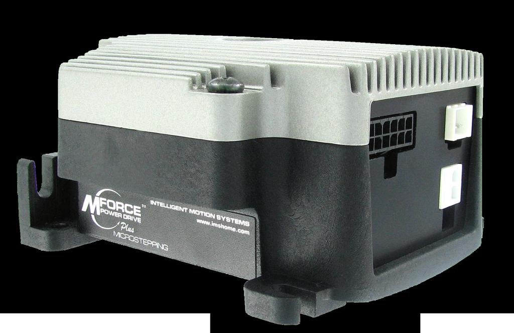
13 SECTION 1.1 Introduction to the Microstepping MForce PowerDrive The Microstepping MForce PowerDrive is a high performance, low cost microstepping driver that delivers unsurpassed smoothness and performance achieved through IMS s advanced 2nd generation current control. By applying innovative techniques to control current flow through the motor, resonance is significantly dampened over the entire speed range and audible noise is reduced. Microstepping MForce PowerDrives accept a broad input voltage range from +12 to +75 VDC, delivering enhanced performance and speed. Oversized input capacitors are used to minimize power line Figure 1.1.1: Microstepping MForce PowerDrive surges, reducing problems that can occur with long runs and multiple drive systems. An extended operating range of 40 to +85 C provides long life, trouble free service in demanding environments. The high, per phase output current of up to 5 Amps RMS, 7 Amps Peak, allows the extremely compact MForce PowerDrive to control a broad array of motors from size 23 to size 42. The microstepping drive accepts up to 20 resolution settings from full to 256 microsteps per full step, including: degrees, metric and arc minutes. These settings may be changed on-the-fly or downloaded and stored in nonvolatile memory with the use of a simple GUI which is provided. This eliminates the need for external switches or resistors. Parameters are changed via an SPI port. The versatile Microstepping MForce PowerDrive comes with dual mounting configurations to fit various system needs. All interface connections are accomplished using pluggable locking wire crimp connectors. Optional cables are available for ease of connecting and configuring the MForce, and are recommended with first order. The Microstepping MForce PowerDrive is a compact, powerful and inexpensive solution that will reduce system cost, design and assembly time for a large range of applications. Configuring The IMS SPI Motor Interface software is an easy to install and use GUI for configuring the Microstepping MForce PowerDrive from a computer's USB port. GUI access is via the IMS SPI Motor Interface included on the CD shipped with the product, or from Optional cables are available for ease of connecting and configuring the MForce. The IMS SPI Motor Interface features: Easy installation. Automatic detection of MForce version and communication configuration. Will not set out-of-range values. Tool-tips display valid range setting for each option. Simple screen interfaces. Part 1: Hardware Specifications 1-5
14 Features and Benefits High Performance Microstepping Driver Advanced 2nd Generation Current Control for Exceptional Performance and Smoothness Single Supply: +12 to +75 VDC Low Cost Extremely Compact High Output Current: Up to 5 Amps RMS, 7 Amps Peak (Per Phase) 20 Microstep Resolutions up to 51,200 Steps Per Rev Including: Degrees, Metric, Arc Minutes Optically Isolated Logic Inputs will Accept +5 to +24 VDC Signals, Sourcing or Sinking Automatic Current Reduction Configurable: Motor Run/Hold Current Motor Direction vs. Direction Input Microstep Resolution Clock Type: Step and Direction, Quadrature, Step Up and Step Down Programmable Digital Filtering for Clock and Direction Inputs Current and Microstep Resolution May Be Switched On-The-Fly Dual Mounting Configurations Power, Motor and Signal Interface via locking wire crimp style connectors. Graphical User Interface (GUI) for Quick and Easy Parameter Setup 1-6 Microstepping MForce PowerDrive Manual Revision R080608
15 SECTION 1.2 General Specifications Microstepping MForce PowerDrive Detailed Specifications Electrical Specifications Input Voltage (+V) Range* Max Power Supply Current (Per MForce PowerDrive)* Output Current RMS Output Current Peak (Per Phase) +12 to +75 VDC 4 Amps 5 Amps 7 Amps * Actual Power Supply Current will depend on Voltage and Load. Table 1.2.1: Electrical Specifications Thermal Specifications Heat Sink Temperature -40 C to +85 C Table 1.2.2: Thermal Specifications I/O Specifications Isolated Inputs Step Clock, Direction and Enable Resolution Voltage Range (Sourcing or Sinking) Current (+5 VDC Max) Current (+24 VDC Max) Table 1.2.3: I/O Specifications 10 Bit +5 to +24 VDC 8.7 ma 14.6 ma Communications Specifications Protocol Table 1.2.4: Communications Specifications SPI Motion Specifications Microstep Resolution Number of Resolutions 20 Available Microsteps Per Revolution =0.01 deg/µstep 2=1 arc minute/µstep 3=0.001 mm/µstep Digital Filter Range Clock Types Step Frequency (Max) Step Frequency Minimum Pulse Width Table 1.2.5: Motion Specifications 50 ns to 12.9 µs (10 MHz to 38.8kHz) Step/Direction, Quadrature, Clock Up/ Clock Down 5.0 MHz 100 ns Part 1: Hardware Specifications 1-7
16 Setup Parameters The following table illustrates the setup parameters. These are easily configured using the IMS SPI Motor Interface configuration utility. An optional Parameter Setup Cable is available and recommended with the first order. Microstepping MForce PowerDrive Setup Parameters Name Function Range Units Default MHC Motor Hold Current 0 to 100 percent 5 MRC Motor Run Current 1 to 100 percent 25 MSEL Microstep Resolution 1, 2, 4, 5, 8, 10, 16, 25, 32, 50, 64, 100,108, 125, 127,128, 180, 200, 250, 256 µsteps per full step DIR Motor Direction Override 0/1 CW HCDT Hold Current Delay Time 0 or msec 500 CLK TYPE CLK IOF Clock Type Clock and Direction Filter Step/Dir. Quadrature, Up/Down (CW/CCW) 50 ns to 12.9 µs (10 MHz to 38.8kHz) 256 Step/Dir ns (MHz) 200nS(2.5 MHz) USER ID User ID Customizable 1-3 characters IMS WARN TEMP Warning Temperature 0 to +125 ºC 80 EN ACT Enable Active High/Low High or Low High PWM MSK PWM Mask 0 to PWM PER PWM Duty Cycle 0 to 95 Percent 90% PWM FREQ PWM Frequency Range 0 to (20kHz to 60 khz) PWM CTL PWM Control See Section 2.4 See Section Table 1.2.6: Setup Parameters Mechanical Specifications - Dimensions in Inches (mm) (88.21) TYP. (7.82 TYP.) ±0.01 (4.06 ±0.25) (53.75) P1 P3 2X (2X 14.73) (5.72) 3.00 ±0.01 (76.2 ±0.25) P4 Ø ±0.01 (Ø 4.75 ±0.25) 2X #8 Screws for End Mount (98.98) TYP. (74.45 TYP.) Ø ±0.01 Thru (Ø 4.06 ±0.25 Thru) 4X #6 Screws for Flat Mount TYP. (10.59 TYP.) (74.93) (88.21) Figure 1.2.1: MForce PowerDrive Mechanical Specifications 1-8 Microstepping MForce PowerDrive Manual Revision R080608
17 Pin Assignment and Description P1 12-Pin Locking Wire Crimp Connector Option - Power, I/O and SPI Communications Pin Assignment - P1 Power, I/O and SPI Connections Pin # Function Description Pin 1 N/C No Connect Pin 2 N/C No Connect Pin 3 Opto Reference The Signal applied to the Optocoupler Reference will determine the sinking/ or sourcing configuration of the inputs. To set the inputs for sinking operation, a +5 to +24 VDC supply is connected. If sourcing, the Reference is connected to Ground. Pin 4 Pin 5 Pin 6 Step Clock/Channel A/ Clock Up Enable Direction/Channel B/ Clock Down Step Clock input. The step clock input will receive the clock pulses which will step the motor 1 step for each pulse. It may also receive quadrature and clock up type inputs if so configured. Enable/Disable Input will enable or disable the driver output to the motor. In the disconnected state the driver outputs are enabled in either sinking or sourcing configuration. Direction input. The axis direction will be with respect to the state of the Direction Override Parameter. It may also receive quadrature and clock up type inputs if so configured. Pin 7 +5 VDC Output Supply voltage for the MD-CC Cable ONLY! Pin 8 SPI Clock The Clock is driven by the SPI Master. The clock cycles once for each data bit. Pin 9 GND Communications Ground. Pin 10 MISO Master-In/Slave-Out. Carries output data from the MFM back to the SPI Master. Pin 11 CS SPI Chip Select. This signal is used to turn communications on multiple MFM units on or off. Pin 12 MOSI Master-Out/Slave-In. Carries output data from the SPI Master to the MFM. Table 1.2.7: P1 Connector Power, I/O and SPI Communications NEED A CABLE? The following cables and converters are available to interface with P1: 12-Pin Locking Wire Crimp PD FL3 NEED A CABLE? The following cables and converters are available to interface communications with USB to SPI: MD-CC See Appendix A for details P1 Recommended Connector Shell and Pins Shell: AMP P/N Pins: 12 x AMP P/N Wire: 22 AWG Shielded Twisted Pair Figure 1.2.2: P1 12-Pin Locking Wire Crimp Pin Configuration Part 1: Hardware Specifications 1-9
18 NEED A CABLE? The following cables and converters are available to interface with P3: 2-Pin Locking Wire Crimp PD FL3 P3 Connector - DC Power, 2-Pin Locking Wire Crimp Pin Assignment - P3 Power 2-Pin Locking Function Wire Crimp Description Pin 1 +V +12 to +75 VDC, 4 Amps Maximum per MDrive34Plus. Pin 2 GND Power Supply Return. Table 1.2.8: P3 Connector WARNING! Do not plug or unplug DC Power with power applied. Recommended Connector Shell and Pins Shell: Molex P/N Pins: 2 x Molex P/N Wire: 18 AWG Shielded Twisted Pair 2 1 P3 Figure 1.2.3: P3 2-Pin Locking Wire Crimp Pin Configuration P4 Connector - Motor NEED A CABLE? The following cables and converters are available to interface with P4: 4-Pin Locking Wire Crimp PD04-MF34-FL3 Pin Assignment - P4 Motor 5-Pin Locking Function Wire Crimp Description Pin 1 Phase A Phase A Motor Output Pin 2 Phase A Phase A Motor Return Pin 3 Phase B Phase B Motor Output Pin 4 Phase B Phase B Motor Return Recommended Cable PD04-MF34-FL3 Table 1.2.9: P4 Connecter Recommended Connector Shell and Pins Shell: Molex P/N Pins: 4 x Molex P/N Wire: 16 AWG Shielded Twisted Pair P Figure 1.2.4: P4 4-Pin Locking Wire Crimp Pin Configuration 1-10 Microstepping MForce PowerDrive Manual Revision R080608
19 Options and Accessories Parameter Setup Cable and Adapters The optional 12.0' (3.6m) parameter setup cable part number MD-CC facilitates communications and I/O wiring and is recommended with first order. USB to SPI...MD-CC Prototype Development Cables To speed prototype development, these cables connect to user interface via flying leads with MForce mating connector on opposite end. Mating connector to MForce 12-pin communications and I/O interface: Mating connector to 12-pin pluggable locking wire crimp plugs into MForce this cable will only be used if the SPI communications is provided by the user. 10.0' (3.0m)... PD FL3 Mating connector to MForce 2-pin power interface: 10.0' (3.0m)... PD FL3 Mating connector to MForce 4-pin motor interface: 10.0' (3.0m)... PD04-MF34-FL3 Mating Connector Kits Use to build your own cables. Kits contain 5 mating shells with pins. Cable not supplied. Manufacturer s crimp tool recommended. Mates to connector: 12-Pin Wire Crimp...CK-03 2-Pin Wire Crimp...CK-05 4-Pin Wire Crimp... CK-07 Part 1: Hardware Specifications 1-11
20 Page Intentionally Left Blank 1-12 Microstepping MForce PowerDrive Manual Revision R080608

21 TM FORCE MICRO DRIVE MICROSTEPPING Part 2: Interfacing and Configuring Section 2.1: Mounting and Connection Recommendations Section 2.2: Logic Interface and Connection Section 2.3: Connecting SPI Communications Section 2.4: Using the IMS SPI Motor Interface Section 2.5: Using User-Defined SPI Part 2: Interfacing and Configuring 1
22 Page Intentionally Left Blank 2 Microstepping MForce PowerDrive Manual Revision R080608
23 SECTION 2.1 Mounting and Connection Guidelines Mounting Recommendations The Microstepping MForce PowerDrive may be mounted two ways: end mounted or flat mounted End mounting will use #8 hardware, flat mounting will use standard #6 hardware. Do not exceed the recommended mounting torque specification. The diagrams in Figures and illustrate the mounting methods. Recommended Tightening Torque: 7-8 lb-in ( N-cm) NOTE: Mounting Hardware is not supplied. Mounting Hardware 4 x #6-32 Screw 4 x #6 Split Lockwasher 4 x #6 Flat Washer Mounting Hardware (Metric) 4 x M Screw 4 x M3.5 Split Lockwasher 4 x M3.5 Flat Washer MForce PowerDrive Mounting Surface Mounting Hole Pattern (Not to Scale) (74.93 Use #36 Drill Size (2.9 mm) Tap to #6-32 (M ) 4 PL TYP (74.45 TYP) Figure 2.1.1: Base Mounting the MForce PowerDrive Part 2: Interfacing and Configuring 3
24 NOTE: Ensure that proper clearance is allowed for wiring and cabling. Especially when end mounting the device. Recommended Tightening Torque: 8-9 lb-in ( N-cm) NOTE: Mounting Hardware is not supplied. Mounting Surface Mounting Hardware 2 x #8-32 Screw 2 x #8 Split Lockwasher 2 x #8 Flat Washer Mounting Hardware (Metric 2 x M Screw 2 x M4 Split Lockwasher 2 x M4 Flat Washer Mounting Hole Pattern Use #29 Drill Size (3.3 mm) Tap to # PL (M4-0.70) TYP (76.20 TYP) Figure 2.1.2: End Mounting the MForce PowerDrive Securing Power Leads and Logic Leads Some applications may require that the MForce and/or the connected motor to move with the axis motion. If this is a requirement of your application, the motor leads must be properly anchored. This will prevent flexing and tugging which can cause damage at critical connection points on the MForce connectors. Layout and Interface Guidelines Logic level cables must not run parallel to power cables. Power cables will introduce noise into the logic level cables and make your system unreliable. Logic level cables must be shielded to reduce the chance of EMI induced noise. The shield needs to be grounded at the signal source to earth. The other end of the shield must not be tied to anything, but allowed to float. This allows the shield to act as a drain. Power supply leads to the MForce PowerDrive need to be twisted. If more than one driver is to be connected to the same power supply, run separate power and ground leads from the supply to each driver. 4 Microstepping MForce PowerDrive Manual Revision R080608
25 Rules of Wiring Power Supply and Motor wiring should be shielded twisted pairs, and run separately from signalcarrying wires. A minimum of one twist per inch is recommended. Motor wiring should be shielded twisted pairs using 20 gauge, or for distances of more than 5 feet, 18 gauge or better. Power ground return should be as short as possible to established ground. Power supply wiring should be shielded twisted pairs of 18 gauge for less than 4 amps DC and 16 gauge for more than 4 amps DC. Rules of Shielding The shield must be tied to zero-signal reference potential. It is necessary that the signal be earthed or grounded, for the shield to become earthed or grounded. Earthing or grounding the shield is not effective if the signal is not earthed or grounded. Do not assume that Earth ground is a true Earth ground. Depending on the distance from the main power cabinet, it may be necessary to sink a ground rod at the critical location. The shield must be connected so that shield currents drain to signal-earth connections. The number of separate shields required in a system is equal to the number of independent signals being processed plus one for each power entrance. The shield should be tied to a single point to prevent ground loops. A second shield can be used over the primary shield; however, the second shield is tied to ground at both ends. Recommended Wiring The following wiring/cabling is recommended for use with the MForce PowerDrive: Logic Wiring...22 AWG Wire Strip Length (6.0 mm) Power and Ground...18 AWG Shielded Twisted Pair* Motor...16 AWG Shielded Twisted Pair *See Table if using a power cable longer than 10 feet. The Gauge used is dependant upon supply current and legnth. Recommended Mating Connectors and Pins Logic and SPI Communications (P1) Mating Connector Kit... CK-03 Communications Converter Cable... MD-CC Manufacturer PNs 12-pin Locking Wire Crimp Connector Shell... Tyco Crimp Pins...Tyco Crimp Tool...Tyco Power - P3 Mating Connector Kit... CK-05 Prototype Development Cable... PD FL3 Manufacturer PNs 2-pin Locking Wire Crimp Connector Shell... Molex Crimp Pins... Molex Brass Crimp Tool... Molex Motor - P4 Mating Connector Kit... CK-07 Prototype Development Cable... PD02-MF34-FL3 Manufacturer PNs 4-pin Locking Wire Crimp Connector Shell... Molex Crimp Pins... Molex Crimp Tool... Molex Part 2: Interfacing and Configuring 5
26 Page Intentionally Left Blank 6 Microstepping MForce PowerDrive Manual Revision R080608


27 SECTION 2.2 Interfacing DC Power Choosing a Power Supply for Your MForce PowerDrive When choosing a power supply for your MForce PowerDrive there are performance and sizing issues that must be addressed. An undersized power supply can lead to poor performance and even possible damage to the device, which can be both time consuming and expensive. However, The design of the MForce PowerDrive is quite efficient and may not require as large a supply as you might suspect. Motors have windings that are electrically just inductors, and with inductors comes resistance and inductance. Winding resistance and inductance result in a L/R time constant that resists the change in current. It requires five time constants to reach nominal current. To effectively manipulate the di/dt or the rate Figure 2.2.1: IMS ISP300 Switch Mode Power Supply of charge, the voltage applied is increased. When traveling at high speeds there is less time between steps to reach current. The point where the rate of commutation does not allow the driver to reach full current is referred to as Voltage Mode. Ideally you want to be in Current Mode, which is when the drive is achieving the desired current between steps. Simply stated, a higher voltage will decrease the time it takes to charge the coil, and therefore will allow for higher torque at higher speeds. Another characteristic of all motors is Back EMF, and though nothing can be done about back EMF, we can give a path of low impedance by supplying enough output capacitance. Back EMF is a source of current that can push the output of a power supply beyond the maximum operating voltage of the driver and as a result could damage the MForce PowerDrive over time. The MForce PowerDrive is very current efficient as far as the power supply is concerned. Once the motor has charged one or both windings of the motor, all the power supply has to do is replace losses in the system. The charged winding acts as an energy storage in that the current will re-circulate within the bridge, and in and out of each phase reservoir. While one phase is in the decaying stage of the variable chopping oscillator, the other phase is in the charging stage, this results in a less than expected current draw on the supply. The MForce PowerDrive is designed with the intention that a user s power supply output will ramp up to greater or equal to the minimum operating voltage. The initial current surge is quite substantial and could damage the driver if the supply is undersized. If a power supply is undersized, upon a current surge the supply could fall below the operating range of the driver. This could cause the power supply to start oscillating in and out of the voltage range of the driver and result in damaging either the supply, driver or both. There are two types of supplies commonly used, regulated and unregulated, both of which can be switching or linear. All have their advantages and disadvantages. An unregulated linear supply is less expensive and more resilient to current surges, however, voltage decreases with increasing current draw. This can cause serious problems if the voltage drops below the working range of the drive. Also of concern is the fluctuations in line voltage. This can cause the unregulated linear supply to be above or below the anticipated voltage. A regulated supply maintains a stable output voltage, which is good for high speed performance. They are also not bothered by line fluctuations, however, they are more expensive. Depending on the current regulation, a regulated supply may crowbar or current clamp and lead to an oscillation that as previously stated can lead to damage. Back EMF can cause problems for regulated supplies as well. The current regeneration may be too large for the regulated supply to absorb and may lead to an over voltage condition. Switching supplies are typically regulated and require little real-estate, which makes them attractive. However, their output response time is slow, making them ineffective for inductive loads. IMS has designed a series of low cost miniature non-regulated switchers that can handle the extreme varying load conditions which makes them ideal for the MForce PowerDrive. Part 2: Interfacing and Configuring 7
28 DC Power Supply Recommendations The power requirements for the Microstepping MForce PowerDrive are: Output Voltage to +75 VDC (Includes Back EMF) Current (max. per unit)...4a (Actual power supply current requirement will depend upon voltage and load) Recommended IMS Power Supplies IMS unregulated linear and unregulated switching power supplies are the best fit for IMS drive products. IP804 Unregulated Linear Supply Input Range 120 VAC Versions VAC 240 VAC Versions VAC Output (All Measurements were taken at 25 C, 120 VAC, 60 Hz) No Load Output Voltage Amps Half Load Output Amps Full Load output Amps IP806 Unregulated Linear Supply Input Range 120 VAC Versions VAC 240 VAC Versions VAC Output (All Measurements were taken at 25 C, 120 VAC, 60 Hz) No Load Output Voltage Amps Half Load Output Amps Full Load Output Amps ISP300-7 Unregulated Switching Supply Input Range 120 VAC Versions VAC 240 VAC Versions VAC Output (All Measurements were taken at 25 C, 120 VAC, 60 Hz) No Load Output Voltage Amps Continuous Output Rating Amps Peak Output Rating Amps 8 Microstepping MForce PowerDrive Manual Revision R080608
29 Basic DC Power Connection Unregulated Linear or Switching Power Supply Power Ground! WARNING! Do not connect or disconnect cabling while power is applied! WARNING! DO NOT connect or disconnect power leads when power is applied! Disconnect the AC power side to power down the DC power supply. +VDC Shield to Earth Ground Optional Prototype Development Cable: PD FL3 + P3 Pin 2 Pin 1 Figure 2.2.2: MForce PowerDrive DC Power Connection Recommended Power and Cable Configurations Cable length, wire gauge and power conditioning devices play a major role in the performance of your MForce PoweDrive. Example A demonstrates the recommended cable configuration for DC power supply cabling under 50 feet long. If cabling of 50 feet or longer is required, the additional length may be gained by adding an AC power supply cable (see Examples B & C). Correct AWG wire size is determined by the current requirement plus cable length. Please see Table for recommended wire gauges. Example A: DC Power Cabling Under 50 Feet DC Voltage from Power Supply 500 µf Per Amp + - Cable Length less than 50 Feet Type RFI Filter Required Current - + P3:2 P3:1 Shield to Earth Ground on Supply End Only Shielded Twisted Pair Ferrite Beads Figure 2.2.3: DC Cabling - Under 50 Feet Part 2: Interfacing and Configuring 9
30 WARNING! DO NOT connect or disconnect power leads when power is applied! Disconnect the AC power side to power down the DC power supply. Example B: AC Power to Full Wave Bridge Cabling Over 50 Feet Transformer - 10 to 28 VAC RMS for 48 VDC Systems 20 to 48 VAC RMS for 75 VDC Systems Type RFI Filter Required Current Shielded Twisted Pair NOTE: Connect the cable illustrated in Figure to the output of the Full Wave Bridge + Shield to Earth Ground on Supply End Only Cable Length as required Figure 2.2.4: AC To Full Wave Bridge Rectifier, Cabling over 50 Feet Full Wave Bridge - Example C Cabling 50 Feet or Greater, AC Power to Power Supply Shielded Twisted Pair Type RFI Filter Required Current NOTE: Connect the cable illustrated in Example A to the output of the Power Supply 120 or 240 VAC Dependent on Power Supply + - DC Volts Out Shield to Earth Ground on Supply End Only Cable Length as required Power Supply Figure 2.2.5: AC Cabling - 50 Feet or Greater - AC To Power Supply MForce PowerDrive Recommended Power Supply Cable AWG 1 Amperes (Peak) 3 Amperes (Peak) Length (Feet) * 75* 100* Length (Feet) * 75* 100* Minimum AWG Minimum AWG Amperes (Peak) 4 Amperes (Peak) Length (Feet) * 75* 100* Length (Feet) * 75* 100* Minimum AWG Minimum AWG *Use the alternative methods illustrated in examples B and C when cable length is 50 feet. Also, use the same current rating when the alternate AC power is used. Table 2.2.1: Recommended Wire Gauges 10 Microstepping MForce PowerDrive Manual Revision R080608
31 SECTION 2.3 Motor Selection and Interface Selecting a Motor When selecting a stepper motor for your application, there are several factors that need to be taken into consideration: How will the motor be coupled to the load? How much torque is required to move the load? How fast does the load need to move or accelerate? What degree of accuracy is required when positioning the load? While determining the answers to these and other questions is beyond the scope of this document, they are details that you must know in order to select a motor that is appropriate for your application. These details will affect everything from the power supply voltage to the type and wiring configuration of your stepper motor. The current and microstepping settings of your Microstepping MForce PowerDrive will also be affected. Types and Construction of Stepping Motors The stepping motor, while classed as a DC motor, is actually an AC motor that is operated by trains of pulses. Although it is called a stepping motor, it is in reality a polyphase synchronous motor. This means it has multiple phases wound in the stator and the rotor is dragged along in synchronism with the rotating magnetic field. The MForce PowerDrive is designed to work with the following types of stepping motors: 1) Permanent Magnet (PM) 2) Hybrid Stepping Motors Hybrid stepping motors combine the features of the PM stepping motors with the features of another type of stepping motor called a variable reluctance motor (VR). VR motors are low torque and load capacity motors which are typically used in instrumentation. The MForce PowerDrive cannot be used with VR motors as they have no permanent magnet. On hybrid motors, the phases are wound on toothed segments of the stator assembly. The rotor consists of a permanent magnet with a toothed outer surface which allows precision motion accurate to within ± 3 percent. Hybrid stepping motors are available with step angles varying from 0.45 to 15 with 1.8 being the most commonly used. Torque capacity in hybrid steppers ranges from ounce-inches. Because of their smaller step angles, hybrid motors have a higher degree of suitability in applications where precise load positioning and smooth motion is required. Sizing a Motor for Your System The MForce PowerDrive is a bipolar driver which works equally well with both bipolar and unipolar motors (i.e. 8 and 4 lead motors, and 6 lead center tapped motors). To maintain a given set motor current, the MForce PowerDrive chops the voltage using a variable chopping frequency and a varying duty cycle. Duty cycles that exceed 50% can cause unstable chopping. This characteristic is directly related to the motor s winding inductance. In order to avoid this situation, it is necessary to choose a motor with a low winding inductance. The lower the winding inductance, the higher the step rate possible. Winding Inductance Since the MForce PowerDrive is a constant current source, it is not necessary to use a motor that is rated at the same voltage as the supply voltage. What is important is that the MForce PowerDrive is set to the motor s rated current. The higher the voltage used the faster the current can flow through the motor windings. This in turn means a higher step rate, or motor speed. Care should be taken not to exceed the maximum voltage of the driver. Therefore, in choosing a motor for a system design, the best performance for a specified torque is a motor with the lowest possible winding inductance used in conjunction with highest possible driver voltage. The winding inductance will determine the motor type and wiring configuration best suited for your system. While the equation used to size a motor for your system is quite simple, several factors fall into play at this point. The winding inductance of a motor is rated in millihenrys (mh) per Phase. The amount of inductance will depend on the wiring configuration of the motor. Part 2: Interfacing and Configuring 11
32 NOTE: In calculating the maximum phase inductance, the minimum supply output voltage should be used when using an unregulated supply. Actual Inductance Seen By the Driver Specified Per Phase Inductance PHASE A Actual Inductance Seen By the Driver Specified Per Phase Inductance PHASE A PHASE A PHASE A PHASE B PHASE B PHASE B PHASE B 8 Lead Stepping Motor Series Configuration (Note: This exampl e also applies to the 6 lead motor full copper configuration and to 4 lead stepping motors) A 8 Lead Stepping Motor Parallel Configuration (Note: This exampl e also applies to the 6 lead motor half copper configuration) B Figure A & B: Per Phase Winding Inductance The per phase winding inductance specified may be different than the per phase inductance seen by your MForce PowerDrive driver depending on the wiring configuration used. Your calculations must allow for the actual inductance that the driver will see based upon the wiring configuration. Figure 2.3.1A shows a stepper motor in a series configuration. In this configuration, the per phase inductance will be 4 times that specified. For example: a stepping motor has a specified per phase inductance of 1.47mH. In this configuration the driver will see 5.88 mh per phase. Maximum Motor Inductance (mh per Phase) =.2 X Minimum Supply Voltage Figure 2.3.1B shows an 8 lead motor wired in parallel. Using this configuration the per phase inductance seen by the driver will be as specified. Using the following equation we will show an example of sizing a motor for a MForce PowerDrive used with an unregulated power supply with a minimum voltage (+V) of 18 VDC:.2 X 18 = 3.6 mh The recommended per phase winding inductance we can use is 3.6 mh. Recommended IMS Motors IMS also carries a series of 23 and 34 frame enhanced stepping motors that are recommended for use with the MForce PowerDrive. These motors use a unique relationship between the rotor and stator to generate more torque per frame size while ensuring more precise positioning and increased accuracy. The special design allows the motors to provide higher torque than standard stepping motors while maintaining a steadier torque and reducing torque drop-off. Each frame size is available in 3 stack sizes, single or double shaft, with or without encoders. They handle currents up to 2.4 Amps in series or 6 Amps parallel, and holding torque ranges from 90 oz.-in. (M ) to 1303 oz.-in (M ) (64 N-cm to 920 N-cm). These CE rated motors are ideal for applications where higher torque is required. For more detailed information on these motors, please see the IMS Full Line catalog or the IMS web site at 12 Microstepping MForce PowerDrive Manual Revision R080608
33 23 Frame Enhanced (2.4A - Not Available with Double Shaft) Single Shaft Double Shaft M S...N/A M S...N/A M S...N/A 23 Frame Enhanced (3.0A) Single Shaft Double Shaft M S... M D M S... M D M S... M D 23 Frame Enhanced (6.0A) Single Shaft Double Shaft M S... M D M S... M D M S... M D 34 Frame Enhanced (6.3A) Single Shaft Double Shaft M S...M D M S... M D M S... M D IMS also offers 23 and 34 Frame hybrid linear actuators for use with the MForce PowerDrive. Please see the IMS Full Line catalog or the IMS web site at IMS Inside Out Stepper Motors The new inside out stepper (IOS) motor was designed by IMS to bring versatility to stepper motors using a unique multi-functional, hollow core design. This versatile new motor can be converted to a ball screw linear actuator by mounting a miniature ball screw to the front shaft face. Ball screw linear actuators offer long life, high efficiency, and can be field retrofitted. There is no need to throw the motor away due to wear of the nut or screw. The IOS motors offer the following features: The shaft face diameter offers a wide choice of threaded hole patterns for coupling. The IOS motor can be direct coupled in applications within the torque range of the motor, eliminating couplings and increasing system efficiency. The IOS motor can replace gearboxes in applications where gearboxes are used for inertia damping between the motor and the load. The induced backlash from the gearbox is eliminated providing improved bidirectional position accuracy. Electrical or pneumatic lines can be directed through the center of the motor enabling the motors to be stacked end-to-end or applied in robotic end effector applications. The through hole is stationary, preventing cables from being chaffed by a moving hollow shaft. Light beams can be directed through the motor for refraction by a mirror or filter wheel mounted on the shaft mounting face. The IOS motor is adaptable to valves enabling the valve stem to protrude above the motor frame. The stem can be retrofitted with a dial indicator showing valve position. The motor is compatible with IMS bipolar drivers, keeping the system cost low. The IOS motor can operate up to 3000 rpm s. Part 2: Interfacing and Configuring 13
34 The IOS motor is available in the following frames: Frame Size IMS PN 23 Frame...M IOS 34 Frame...M IOSConnecting the Motor The motor leads are connected to the following connector pins: Phase Connector: Pin Phase A... P4: 1 Phase A... P4: 2 Phase B... P4: 3 Phase B... P4: 4 8 Lead Motors 8 lead motors offer a high degree of flexibility to the system designer in that they may be connected in series or parallel, thus satisfying a wide range of applications. Series Connection A series motor configuration would typically be used in applications where a higher torque at lower speeds is required. Because this configuration has the most inductance, the performance will start to degrade at higher speeds. Use the per phase (or unipolar) current rating as the peak output current, or multiply the bipolar current rating by 1.4 to determine the peak output current. Parallel Connection An 8 lead motor in a parallel configuration offers a more stable, but lower torque at lower speeds. But because PHASE A Splice P4 PHASE A PHASE B PHASE B Splice Figure 2.3.2: 8 Lead Motor Series Connections of the lower inductance, there will be higher torque at higher speeds. Multiply the per phase (or unipolar) current rating by 1.96, or the bipolar current rating by 1.4, to determine the peak output current. PHASE A P4 PHASE A PHASE B PHASE B Figure 2.3.3: 8 Lead Motor Parallel Connections 14 Microstepping MForce PowerDrive Manual Revision R080608
35 6 Lead Motors Like 8 lead stepping motors, 6 lead motors have two configurations available for high speed or high torque operation. The higher speed configuration, or half coil, is so described because it uses one half of the motor s inductor windings. The higher torque configuration, or full coil, uses the full windings of the phases. Half Coil Configuration As previously stated, the half coil configuration uses 50% of the motor phase windings. This gives lower inductance, hence, lower torque output. Like the parallel connection of 8 lead motor, the torque output will be more stable at higher speeds. This configuration is also referred to as half copper. In setting the driver output current multiply the specified per phase (or unipolar) current rating by 1.4 to determine the peak output current. PHASE A PHASE A P4 No Connect PHASE B PHASE B No Connect Full Coil Configuration Figure 2.3.4: 6 Lead Half Coil (Higher Speed) Motor Connections The full coil configuration on a six lead motor should be used in applications where higher torque at lower speeds is desired. This configuration is also referred to as full copper. Use the per phase (or unipolar) current rating as the peak output current. PHASE A No Connect P4 PHASE A PHASE B No Connect PHASE B Figure 2.3.5: 6 Lead Half Coil (Higher Speed) Motor Connections Part 2: Interfacing and Configuring 15
36 4 Lead Motors 4 lead motors are the least flexible but easiest to wire. Speed and torque will depend on winding inductance. In setting the driver output current, multiply the specified phase current by 1.4 to determine the peak output current. PHASE A P4 PHASE A PHASE B PHASE B Recommended Motor Cabling Figure 2.3.6: 4 Lead Motor Connections As with the power supply wiring, motor wiring should be run separately from logic wiring to minimize noise coupled onto the logic signals. Motor cabling exceeding 1 in length should be shielded twisted pairs to reduce the transmission of EMI (Electromagnetic Interference) which can lead to rough motor operation and poor system performance. Cable length, wire gauge and power conditioning devices play a major role in the performance of your MForce PowerDrive and Stepper Motor. NOTE: The length of the DC power supply cable between the MForce PowerDrive and the Motor should not exceed 50 feet. Example A demonstrates the recommended cable configuration for the MForce PowerDrive to Motor cabling under 50 Feet long. If cabling of 50 feet or longer is required, the additional length can be gained with the cable configuration in Example B. Correct AWG wire size is determined by the current requirement plus cable length. Please see Table on the following page. Example A: Motor Cabling Less Than 50 Feet MForce PowerDrive Phase Outputs A A B B Shield to Earth Ground on Supply End Only Cable Length less than 50 Feet Shielded/Twisted Pair Ferrite Beads Figure 2.3.7: Motor Cabling Less than 50 Feet Motor Connections A A B B 16 Microstepping MForce PowerDrive Manual Revision R080608
37 Example B: Motor Cabling Greater Than 50 Feet A Common Mode Line Filters (2x) *L 0.5 MH Cable Length as required Shielded/Twisted Pair Motor Connections A MForce PowerDrive Phase Outputs A B B Ferrite Beads A B B Shield to Earth Ground on Supply End Only * 0.5 MH is a typical starting point for the Common Mode Line Filters. By increasing or decreasing the value of L you can set the drain current to a minimum to meet your application s requirements. Figure 2.3.8: Motor Cableing Greater than 50 Feet Recommended Motor Cable AWG Sizes MForce PowerDrive Recommended Motor Cable AWG 1 Amperes (Peak) 5 Amperes (Peak) Length (Feet) * 75* 100* Length (Feet) * 75* 100* Minimum AWG Minimum AWG Amperes (Peak) 6 Amperes (Peak) Length (Feet) * 75* 100* Length (Feet) * 75* 100* Minimum AWG Minimum AWG Amperes (Peak) 7 Amperes (Peak) Length (Feet) * 75* 100* Length (Feet) * 75* 100* Minimum AWG Minimum AWG Amperes (Peak) *Use the alternative methods illustrated in example Length (Feet) * 75* 100* B when cable length is 50 feet. Also, use the same current rating when the alternate AC power is used. Minimum AWG Table 2.3.1: Recommended Wire Gauges Part 2: Interfacing and Configuring 17
38 Page Intentionally Left Blank 18 Microstepping MForce PowerDrive Manual Revision R080608
39 SECTION 2.4 Logic Interface and Connection Optically Isolated Logic Inputs The Microstepping MForce PowerDrive has three optically isolated logic inputs which are located on connector P1. These inputs are isolated to minimize or eliminate electrical noise coupled onto the drive control signals. Each input is internally pulled-up to the level of the optocoupler supply and may be connected to sinking or +5 to +24 VDC sourcing outputs on a controller or PLC. These inputs are: 1] Step Clock (SCLK)/Quadrature (CH A)/Clock UP 2] Direction (DIR)/Quadrature (CH B)/ Clock DOWN 3] Enable (EN) Of these inputs only step clock and direction are required to operate the Microstepping MForce PowerDrive. Isolated Logic Input Pins and Connections The following diagram illustrates the pins and connections for the Microstepping MForce PowerDrive family of products. Careful attention should be paid to verify the connections on the model Microstepping MForce Power- Drive you are using. Isolated Logic Input Characteristics Enable Input This input can be used to enable or disable the driver output circuitry. Leaving the enable switch open (Logic HIGH, Disconnected) for sinking or sourcing configuration, the driver outputs will be enabled and the step clock pulses will cause the motor to advance. When this input switch is closed (Logic LOW) in both sinking Inputs Configured as Sinking +5 to +24VDC Pin 3 Pin 5: Enable Pin 3: Opto Supply Inputs Configured as Sourcing Pin 3 Controller I/O Ground Pin 4: Step/Clock Pin 6: Direction Figure 2.4.1: Isolated Logic Pins and Connections Part 2: Interfacing and Configuring 19
40 and sourcing configurations, the driver output circuitry will be disabled. Please note that the internal sine/cosine position generator will continue to increment or decrement as long as step clock pluses are being received by the Microstepping MForce PowerDrive. Clock Inputs The Microstepping MForce PowerDrive features the ability to configure the clock inputs based upon how the user will desire to control the drive. By default the unit is configured for the Step/Direction function. Step Clock The step clock input is where the motion clock from your control circuitry will be connected. The motor will advance one microstep in the plus or minus direction (based upon the state of the direction input) on the rising edge of each clock pulse. The size of this increment or decrement will depend on the microstep resolution setting. Direction The direction input controls the CW/CCW direction of the motor. The input may be configured as sinking or sourcing based upon the state of the Optocoupler Reference. The CW/CCW rotation, based upon the state of the input may be set using the IMS Motor Interface software included with the Microstepping MForce PowerDrive. Quadrature The Quadrature clock function would typically be used for following applications where the Microstepping MForce PowerDrive would be slaved to an MForce PowerDrive Microstepping (or other controller) in an electronic gearing application. Up/Down The Up/Down clock would typically be used in a dualclock direction control application. Input Timing The direction input and the microstep resolution inputs are internally synchronized to the positive going edge of the step clock input. When a step clock pulse goes HIGH, the state of the direction input and microstep resolution settings are latched. Any changes made to the direction and/ or microstep resolution will occur on the rising edge of the step clock pulse following this change. Run and Hold Current changes are updated immediately. The following figure and table list the timing specifications. Step/Direction Function Step Clock Direction Quadrature Function Channel A Channel B Up/Down Function CW CCW Input Filtering The clock inputs may also be filtered using the Clock IOF pull down of the IMS SPI Motor Interface. The filter range is from 50 ns (10 MHz) to 12.9 µsec. (38.8 khz). The configuration parameters for the input filtering is covered in detail in Section 2.4: Configuring the Microstepping MForce PowerDrive. Figure 2.4.2: Input Clock Functions 20 Microstepping MForce PowerDrive Manual Revision R080608
41 STEP/DIRECTION TIMING TDH Direction TDSU Step TSH TSL QUADRATURE TIMING Channel A Direction Change TCHL TDC Channel B TCHL UP/DOWN TIMING Step Up TSH TSL TDC TDC Step Down TSH TSL Figure 2.4.3: Clock Input Timing Characteristics Clock Input Timing Type and Value Symbol Parameter Step/Direction Step Up/Down Quadrature Units T DSU T Direction Set Up 50 ns min T DH T Direction Hold 100 ns min T SH T Step High ns min T SL T Step Low ns min T DL T Direction Change ns min T CHL T Channel High/Low 400 ns min F SMAX F Step Maximum 5 5 MHz Max F CHMAX F Channel Maximum 1.25 MHz Max F ER F Edge Rate 5 MHz Max Table 2.4.1: Input Clocks Timing Table Part 2: Interfacing and Configuring 21
42 NOTE: When connecting the Optocoupler Supply, it is recommended that you do not use MForce Power Ground as Ground as this will defeat the optical isolation. Optocoupler Reference The Microstepping MForce PowerDrive Logic Inputs are optically isolated to prevent electrical noise being coupled into the inputs and causing erratic operation. There are two ways that the Optocoupler Reference will be connected depending whether the Inputs are to be configured as sinking or sourcing. Input Type Sinking Sourcing Optocoupler Reference Optocoupler Reference Connection +5 to +24 VDC Controller Ground Table 2.4.2: Optocoupler Reference Connection +5 VDC Optocoupler Reference Input (Step Clock, Direction, Enable) Constant Current Source Optocoupler To Drive Logic Microstepping MForce PowerDrive Figure 2.4.4: Optocoupler Input Circuit Diagram 22 Microstepping MForce PowerDrive Manual Revision R080608
43 Input Connection Examples The following diagrams illustrate possible connection/application of the Microstepping MForce PowerDrive Logic Inputs. Open Collector Interface Example NPN Open Collector Interface (Sinking) +5 to +24VDC + Optocoupler Reference Microstepping MForce PowerDrive Controller Output Input Controller Ground PNP Open Collector Interface (Sourcing) Controller Output +5 to +24VDC + Optocoupler Reference Microstepping MForce PowerDrive Input Controller Ground Figure 2.4.5: Open Collector Interface Example Part 2: Interfacing and Configuring 23
44 Switch Interface Example Switch Interface (Sinking) +5 to +24VDC GND + Optocoupler Reference Microstepping MForce PowerDrive SPST Switch Enable Input Switch Interface (Sourcing) +5 to +24VDC GND + Optocoupler Reference Microstepping MForce PowerDrive SPST Switch Enable Input Figure 2.4.6: Switch Interface Example 24 Microstepping MForce PowerDrive Manual Revision R080608
45 Minimum Required Connections The connections shown are the minimum required to operate the Microstepping MForce PowerDrive. These are illustrated in both Sinking and Sourcing Configurations. Please reference the Pin Configuration diagram and Specification Tables for the Microstepping MForce PowerDrive connector option you are using. Opto Reference* * The Opto Reference Will set the Sink/Source Configuration of the Inputs Sinking: OptoRef = +5 to +24 VDC Sourcing: OptoRef = Ground Power Ground +V (+12 to +48) Step Direction P1 P3 ØA ØB ØA P4 ØB MForce PowerDrive Front 12-Pin Wire Crimp at P1 Shown. See Specifications for Pin Numbering for other versions. Stepping Motor Figure 2.4.7: Minimum Required Connections Part 2: Interfacing and Configuring 25
46 SECTION 2.5 Connecting SPI Communications Connecting the SPI Interface The SPI (Serial Peripheral Interface) is the communications and configuration interface. For prototyping we recommend the purchase of the parameter setup cable MD-CC This cable connect from a computers USB port directly into the P2 connector. For more information on prototype development cables, please see Appendix: Connectivity. SPI Signal Overview +5 VDC (Output) This output is a voltage supply for the setup cable only. It is not designed to power any external devices. SPI Clock The Clock is driven by the Master and regulates the flow of the data bits. The Master may transmit data at a variety of baud rates. The Clock cycles once for each bit that is transferred. Logic Ground This is the ground for all Communications. MISO (Master In/Slave Out) Carries output data from the Microstepping MForce PowerDrive units back to the SPI Master. Only one MForce PowerDrive can transmit data during any particular transfer. CS (SPI Chip Select) This signal is used to turn multiple Microstepping MForce PowerDrive units on or off. MOSI (Master Out/Slave In) Carries output data from the SPI Master to the Microstepping MForce PowerDrive. 26 Microstepping MForce PowerDrive Manual Revision R080608
47 SPI Pins and Connections PC Parallel/SPI Port 19 For Use ONLY with IMS Parameter Setup Cable +5 VDC OUT COMM GND 7 9 P1 11 SPI CLOCK MASTER IN/SLAVE OUT MASTER OUT/SLAVE IN CHIP SELECT 12-Pin Locking Wire Crimp Figure 2.5.1: SPI Pins and Connections, 12-Pin Wire Crimp Logic Level Shifting and Conditioning Circuit The following circuit diagram is of a Logic Level shifting and conditioning circuit. This circuit should be used if you are making your own parameter cable and are using a laptop computer with 3.3 V output parallel ports. DB25: 2 DB25: 3 DB25: 4 DB25: R pF R5 C3 R9 R3 100 C pF 100K +5V R10 330pF 100K C5 100K R11 +5V U1:A HCT V 4 5 U1:B HCT U1:D 11 HCT125 R P2: 8 R R V P2: 4 P2: 7 CLK CS MOSI NOTE: If making your own parameter setup cable, be advised the 3.3V output parallel ports on some laptop PC s may not be sufficient to communicate with the device without use of a logic level shifting and conditioning Interface. DB25: R R8 4.9K U1:C HCT125 R12 100K 10 +5V + C1.1µF C2 1µF 25V 6 5 MISO P2: VDC P2: 6 GND P2: 5 Figure 2.5.2: Logic Level Shifting and Conditioning Circuit Part 2: Interfacing and Configuring 27
48 SPI Master with Multiple Microstepping MForce PowerDrive It is possible to link multiple Microstepping MForce PowerDrive units in an array from a single SPI Master by wiring the system and programming the user interface to write to multiple chip selects. Each MForce on the bus will have a dedicated chip select. Only one system MForce can be communicated with/parameters changed at a time. SPI Clock MOSI SPI Master MISO CS Microstepping MForce PowerDrive Figure 2.5.3: SPI Master with a Single Microstepping MForce PowerDrive SPI Clock MOSI SPI Master MISO CS1 CS2 Microstepping MForce PowerDrive #1 Microstepping MForce PowerDrive #2 Figure 2.5.4: SPI Master with Multiple Microstepping MForce PowerDrives 28 Microstepping MForce PowerDrive Manual Revision R080608
49 SECTION 2.6 Using the IMS SPI Motor Interface Installation The IMS SPI Motor Interface is a utility that easily allows you to set up the parameters of your Microstepping MForce PowerDrive. It is available on the IMS web site at html. 1. Download the SPI Motor Interface software from html to your desktop or other convenient hard drive location. 2. Extract the files from the zip file using WinZip or compatible compression program. 3. Double-click the setup.exe file in the extracted folder. 4. Follow the on-screen instructions. 5. Once IMS SPI Motor Interface is installed, the Microstepping MForce PowerDrive settings can be checked and/or set. Configuration Parameters and Ranges Microstepping MForce PowerDrive Setup Parameters Name Function Range Units Default MHC Motor Hold Current 0 to 100 percent 5 MRC Motor Run Current 1 to 100 percent 25 MSEL DIR HCDT Microstep Resolution Motor Direction Override Hold Current Delay Time 1, 2, 4, 5, 8, 10, 16, 25, 32, 50, 64, 100,108, 125, 127,128, 180, 200, 250, 256 µsteps per full step 256 0/1 CW 0 or msec 500 CLK TYPE Clock Type Step/Dir. Quadrature, Up/Down Step/Dir CLK IOF Clock and Direction Filter 50 ns to 12.9 µs (10 MHz to 38.8kHz) ns (MHz) 50nS (10 MHz) USER ID User ID Customizable 1-3 characters IMS EN ACT WARN TEMP Enable Active High/Low Warning Temperature High/Low High 0 to C 80 Table 2.6.1: Setup Parameters and Ranges Color Coded Parameter Values The SPI Motor Interface displays the parameter values using a predefined system of color codes to identify the status of the parameter Black: the parameter settings currently stored in the device NVM will display as black. Blue: Blue text indicates a changed parameter setting that has not yet been written to the device. Red: Red text indicates an out-of-range value which cannot be written to the device. When an out-of-range parameter is entered into a field, the "set" button will disable, preventing the value to be written to NVM. To view the valid parameter range, hover the mouse pointer over the field. The valid range will display in a tool tip. The color coding is illustrated in Figure Part 2: Interfacing and Configuring 29
 file.")
 Save Motor Settings Save Motor Settings As Exit the Motor Interface Figure 2.6.")
50 Blue: New Value which has not yet been set to NVM. Red: Out of Range Value. The Set Button will disable as the the Motor Interface will not allow an out of range value to be stored. Black: This is the value Currently Stored in NVM Figure 2.6.1: SPI Motor Interface Color Coding IMS SPI Motor Interface Menu Options File > Open: Opens a saved *.mot (Motor Settings) file. > Save: Saves the current motor settings as a *.mot file for later re-use > Save As > Exit - Disconnects from the device and opens the Initialization Dialog. Perform File Operation Open Motor Settings File (*.mot) Save Motor Settings Save Motor Settings As Exit the Motor Interface Figure 2.6.2: SPI Motor Interface File Menu View > Motion Settings: Displays the Motion Settings screen > IO Settings: Displays the IO Settings Screen > Part and Serial Number: Displays the part and serial number View Settings Screen Motion Settings Screen I/O Settings Screen Read-Only Part and Serial Number Screen Figure 2.6.3: SPI Motor Interface View Menu 30 Microstepping MForce PowerDrive Manual Revision R080608

51 Recall! Retrieves the settings from the Microstepping MForce PowerDrive. Upgrade! Recall Last Stored Parameter Settings Figure 2.6.4: SPI Motor Interface Recall Menu Upgrades the Microstepping MForce PowerDrive firmware by placing the device in Upgrade Mode and launching the firmware upgrader utility. Help Toggle MForce into Upgrade Mode for Firmware Upgrade Figure 2.6.5: SPI Motor Interface Upgrade Menu > IMS Internet Tutorials: Link to an IMS Web Site page containing Interactive flash tutorials. > About: Opens the About IMS and IMS SPI Motor Interface Screen. Links to the Software Tutorial page of the IMS Website Figure 2.6.6: SPI Motor Interface Help Menu and About Screen Part 2: Interfacing and Configuring 31

52 Screen 1: The Motion Settings Configuration Screen The IMS SPI Motor Interface Software opens by default to the Motion Settings Screen shown below. Microstep Resolution Selection Holding Current Delay Time Motor Run Current Direction Override Motor Holding Current Load Factory Default Settings Three Character User ID Store Settings to NVM Exit Program Fault/Checksum Error Figure 2.6.7: SPI Motor Interface Motion Settings Screen There are six basic parameters that may be set here: 1. MSEL: Microstep Resolution Select. 2. HCDT: Holding Current Delay Time. 3. MRC: Motor Run Current 4. Motor Holding Current 5. User ID: 3-character ID 6. Direction Override: Allows the user to set the CW/CCW direction of the motor in relation to the Direction Input from the SPI Motor Interface. MSEL (Microstep Resolution Selection) The Microstepping MForce PowerDrive features 20 microstep resolutions. This setting specifies the number of microsteps per step the motor will move. The MForce PowerDrive uses a 200 step (1.8 ) stepping motor which at the highest (default) resolution of 256 will yield 51,200 steps per revolution of the motor shaft. See Table for available Microstep Resolutions. Binary µstep Resolution Settings Microstep Resolution Settings MS=<µSteps/Step> Steps/Revolution MS=<µSteps/ Step> Decimal µstep Resolution Settings Steps/Revolution Additional Resolution Settings (0.01 /µstep) (1 Arc Minute/µStep) (0.001 mm/µstep) Table 2.6.2: Microstep Resolution Settings 32 Microstepping MForce PowerDrive Manual Revision R080608
53 HCDT (Hold Current Delay Time) The HCDT Motor Hold Current Delay sets time in milliseconds for the Run Current to switch to Hold Current when motion is complete. When motion is complete, the Microstepping MForce PowerDrive will reduce the current in the windings of the motor to the percentage specified by MHC when the specified time elapses. MRC (Motor Run Current) The MRC Motor Run Current parameter sets the motor run current to a percentage of the full output current of the MForce PowerDrive driver section. MHC (Motor Hold Current) The MHC parameter sets the motor holding current as a percentage of the full output current of the driver. If the hold current is set to 0, the output circuitry of the driver section will disable when the hold current setting becomes active. The hold current setting becomes active HCDT setting ms following the last clock pulse. DIR (Motor Direction) HC=(%) RC=(%) Run and Hold Current Settings MForce PowerDrive (Amps RMS) Table 2.6.3: Hold and Run Current Percentage Equivalents The DIR Motor Direction parameter changes the motor direction relative to the direction input signal, adapting the direction of the MForce PowerDrive to operate as your system expects. User ID The User ID is a three character (viewable ASCII) identifier which can be assigned by the user. Default is IMS. IMS SPI Motor Interface Button Functions The following appear on all of the IMS SPI Motor Interface screens, but will only be documented here. Factory Clicking the Factory button will load the Microstepping MForce PowerDrive unit's factory default settings into the IMS SPI Motor Interface. Connected/Disconnected Indicator Set Displays the connected/disconnected state of the software, and if connected, the port connected on. Set writes the new settings to the MForce PowerDrive. Un-set settings will display as blue text in the setting fields. Once set they will be in black text. Setting the Parameters will also clear most Fault Conditions. Exit Disconnects and opens the Initialization dialog. Part 2: Interfacing and Configuring 33

 Input Clock Filter Active High/Low State of the Enable Input Warning Temperature Figure 2.6.")
54 Screen 2: I/O Settings Configuration Screen The I/O Settings screen may be accessed by clicking View > IO Settings on the menu bar. This screen is used to configure the Input Clock type, the filtering and the Active High/Low State of the Enable Input. Input Clock Type The Input Clock Type translates the specified pulse source that the motor will use as a reference for establishing stepping resolution based on the frequency. Input Clock Type (Step/Dir, Quadrature or Up/Down) Input Clock Filter Active High/Low State of the Enable Input Warning Temperature Figure 2.6.8: SPI Motor Interface I/O Settings Screen The three clock types supported are: 1. Step/Direction 2. Quadrature 3. Up/Down The Clock types are covered in detail in Section 2.2: Logic Interface and Connection. Input Clock Filter The clock inputs may also be filtered using the Clock IOF pull down of the IMS SPI Motor Interface. The filter range is from 50 ns (10 MHz) to 12.9 µsec. (38.8 khz). Table shows the filter settings. Min. Pulse Input Clock Filter Settings Cutoff Frequency 50 ns 10 MHz 150 ns 3.3 MHz 200 ns 2.5 MHz 300 ns 1.67 MHz 500 ns 1.0 MHz 900 ns 555 khz 1.7 µs khz 3.3 µs 151 khz 6.5 µs 76.9 khz 12.9 µs 38.8 khz Table 2.6.4: Input Clock Filter Settings Enable Active High/Low The parameter sets the Enable Input to be Active when High (Default, Disconnected) or Active when Low. Warning Temperature The parameter sets the temperature at which a TW, or temperature warning fault code will be generated. In the warning condition the MForce PowerDrive will continue to operate as normal. The thermal shutdown is +85 C. 34 Microstepping MForce PowerDrive Manual Revision R080608

55 IMS Part Number/Serial Number Screen The IMS Part Number and Serial Number screen is accessed by clicking "View > Part and Serial Numbers". This screen is read-only and will display the part and serial number, as well as the fault code if existing. IMS may require this information if calling the factory for support. IMS Part # IMS Serial Number Figure 2.6.9: SPI Motor Interface Part and Serial Number Screen Fault Indication All of the IMS SPI Motor Interface Screens have the Fault field visible. This read-only field will display a 2 character error code to indicate the type of fault. The table below shows the error codes. Binary Case* MForce34Plus Microstepping Fault Codes Error Code Description Action To Clear None No Fault 4 CS SPI Checksum Error 8 SC/CS 16 DFLT 32 DATA SPI Checksum Error/ Sector Changing Defaults Checksum Error Settings Checksum Error 64 TW Temperature Warning Error Displayed Error Displayed Error Displayed Error Displayed Error Displayed Write to MDM (Set Button) Write to MDM (Set Button) Write to MDM (Set Button) Write to MDM (Set Button) Write to MDM (Set Button) *All Fault Codes are OR'ed together Table 2.6.5: Microstepping MForce PowerDrive Fault Codes Part 2: Interfacing and Configuring 35


56 NOTE: Once entered into Upgrade Mode, you MUST complete the upgrade. If the upgrade process is incomplete the IMS SPI Motor Interface will continue to open to the Upgrade dialog until the process is completed! Upgrading the Firmware in the Microstepping MForce PowerDrive The IMS SPI Upgrader Screen New firmware releases are posted to the IMS web site at The IMS SPI Motor Interface is required to upgrade your Microstepping MForce PowerDrive product. To launch the Upgrader, click "Upgrade!" on the IMS SPI Motor Interface menu. The Upgrader screen has 4 read-only text fields that will display the necessary info about your Microstepping MForce PowerDrive. Figure : SPI Motor Interface Upgrade Utility 1. Previous Version: this is the version of the firmware currently on your Microstepping MForce PowerDrive. 2. Serial Number: the serial number of your unit. 3. Upgrade Version: will display the version number of the firmware being installed. 4. Messages: the messages text area will display step by step instructions through the upgrade process. Upgrade Instructions Below are listed the upgrade instructions as they will appear in the message box of the IMS SPI Upgrader. Note that some steps are not shown as they are accomplished internally, or are not relevant to the model IMS product you are updating. The only steps shown are those requiring user action. Welcome Message: Welcome to the Motor Interface UPGRADER! Click NEXT to continue. Step 2: Select Upgrade File When this loads, an explorer dialog will open asking you to browse for the firmware upgrade file. This file will have the extension *.ims. Step 3: Connect SPI Cable Step 4: Power up or Cycle Power to the MForce Step 6: Press Upgrade Button Progress bar will show upgrade progress in blue, Message box will read "Resetting Motor Interface" Step 8: Press DONE, then select Port/Reconnect. 36 Microstepping MForce PowerDrive Manual Revision R080608

57 Initialization Screen This screen will be active under five conditions: 1. When the program initially starts up and seeks for a compatible device. 2. The User selects File > Exit when connected to the device. 3. The User clicks the Exit button while connected to the device. 4. The Upgrade Process completes. 5. The SPI Motor Interface is unable to connect to a compatible device. Figure : SPI Motor Interface Initialization Port Menu The Port Menu allows the user to select the COM Port that the device is connected to, either a parallel (LPT) Port, or a Hardware Serial or Virtual Serial Port via USB. The Reconnect option allows the user to reconnect to a unit using the previously used settings. On open or reconnect, the SPI Motor Interface will also try to auto seek for a connected device. Communications Port Operations Select Parallel (LPT) Port Select Serial or USB (VCP) Auto-seek Port and Reconnect to device Figure : SPI Motor Interface Port Menu Part 2: Interfacing and Configuring 37
 PWM Frequency Range PWM Control PWM Mask PWM Frequency Range PWM Period (Duty Cycle) Control Bits Figure 2.6.")
58 Motor Settings Screen (PWM Current Control) The Motor settings screen allows the user to fine tune the settings of the PWM to optimize the current output for a variety of stepping motors. There are four parameters that may be set: PWM Mask PWM Period (Duty Cycle) PWM Frequency Range PWM Control PWM Mask PWM Frequency Range PWM Period (Duty Cycle) Control Bits Figure : Motor Settings Screen PWM Mask The PWM mask parameter prevents the premature end of the forward period caused by switching transients when the motor phase current is at low levels. Adjusting this value can impact the zero-crossing performance of the motor. If experiencing the tick which is inherit in stepper motor systems, this may be minimized or eliminated by adjusting this value. The range of this value is 0 to 255d and will be entered as a decimal value. The Mask will act as a filter on the PWM signal to allow time for any ringing in the output circuitry to settle. This range represents a 8-bit Hex value that specifies the Bridge Reverse Measure Time (REVTM) and the Minimum Bridge Forward On Time (FORTM) ranging from 600 ns to 3.4 µs each (see table and diagram below). Typically these values would be balanced. The table below shows the decimal value for each time. Note that these are typical values and the currents may be unbalanced to fine tune the motor performance. The default value for this parameter is 204 (0xCC), which represents a Reverse Measure Time and Minimum Forward On Time of 2.5 µs. Reverse Measure Time/Minimum Forward On Time Hex Time Hex Time Hex Time Hex Time 0x0 600 ns 0x4 1.0 µs 0x8 1.6 µs 0xC 2.5 µs 0x1 700 ns 0x5 1.1 µs 0x9 1.8 µs 0xD 2.8 µs 0x2 800 ns 0x6 1.2 µs 0xA 2.0 µs 0xE 3.1 µs 0x3 900 ns 0x7 1.4 µs 0xB 2.2 µs 0xF 3.4 µs Table 2.6.6: PWM Mask Settings Reverse Measure Time Min. Forward On Time xDD 0xD (2.8 µs) 0xD (2.8 µs) Convert to Decimal Figure : PWM Mask Bits PWM Mask Value = Microstepping MForce PowerDrive Manual Revision R080608
59 Typical PWM Mask Settings (Currents Balanced) Mask (hex) Mask (dec) REVTM FORTM Mask (hex) Mask (dec) REVTM FORTM 0x ns 600 ns 0x µs 1.6 µs 0x ns 700 ns 0x µs 1.8 µs 0x ns 800 ns 0xAA µs 2.0 µs 0x ns 900 ns 0xBB µs 2.2 µs 0x µs 1.0 µs 0xCC µs 2.5 µs 0x µs 1.1 µs 0xDD µs 2.8 µs 0x µs 1.2 µs 0xEE µs 3.1 µs 0x µs 1.4 µs 0xFF µs 3.4 µs Table 2.6.7: Typical PWM Mask Settings Maximum PWM Duty Cycle (%) Parameter This parameter sets the maximum duty cycle as a percentage of the bridge PWM oscillator period. The range for this parameter is 0 to 95%. The default value for this parameter is 95%. PWM Frequency Range Parameter The PWM Frequency Parameter sets the initial and maximum frequencies for the PWM. As with the MASK parameter, the PWM Frequency is a two part 8-bit hex number which is entered as a decimal value ranging from 0 to 255. The default for this 170 (0xAA) with an initial PWM Frequency of 20 khz and a Maximum of 60 khz. Maximum PWM Frequency (khz) Hex Freq. Hex Freq Hex Freq Hex Freq 0x0 40 0x4 48 0x8 56 0xC 64 0x1 42 0x5 50 0x9 58 0xD 66 0x2 44 0x6 52 0xA 60 0xE 68 0x3 46 0x7 54 0xB 62 0xF 70 Initial PWM Frequency (khz) Hex Freq. Hex Freq Hex Freq Hex Freq 0x0 10 0x4 14 0x8 18 0xC 22 0x1 11 0x5 15 0x9 19 0xD 23 0x2 12 0x6 16 0xA 20 0xE 24 0x3 13 0x7 17 0xB 21 0xF 25 Table 2.6.8: Maximum and Initial PWM Frequency PWM Max. Frequency PWM Initial Frequency x5E 0x5 (50 khz) 0xE (24 khz) Convert to Decimal PWM SFREQ = 94 PWM Frequency Range 24 to 50 khz Figure : PWM Frequency Range Part 2: Interfacing and Configuring 39
60 PWM Control Bits Bit 0x0203 Read/Write Initial Value QUIET SYNC_EN RECIR TODLY[2:0] ENABLE R/W 0 R/W 0 R/W 1 R/W 0 R/W 0 R/W 0 R/W 1 R/W 0 PWMCT Figure : PWM Control Bits Bit 7 QUIET This bit changes PWM operation. When quiet is set, the bridge logic does not enter the reverse measure period, therefore there are fewer transitions. The bridge is disabled during zero cross. This mode is used at rest or when moving very slowly. When quiet is cleared, normal bridge operation is selected. Bit 6 Not used Bit 5 SYNC_EN This bit controls the synchronization of the bridge PWM with the zero cross. When the sync_en bit is set, the bridge PWM will be synchronized with the positive front slope of the sin phase at each zero cross. Bit 4 RECIR This bit controls where the motor current will recirculate within the bridge during the recirculate period. When recirc is set, the motor current will recirculate in the high portion of the bridge. When recir is cleared, the motor current will recirculate in the low portion of the bridge. Bits 3..1 TODLY - Turn on Delay This value sets the bridge control turn on delay to prevent shoot through if a discrete FET bridge is in use. The range is 0 to 350 ns with 50 ns resolution. Each LSB is 50 ns. The default setting for a bridge driver is 50 ns (0x1). Bit 0 ENABLE Bridge Enable, this bit is set at the factory and is inaccessible to the user. Example PWM Settings By Motor Specifications The following settings are based upon IMS settings per motor specifications and should serve as a baseline to work from with regard to the manufacturer specifications of the motor being utilized. Note that these are example settings ONLY! Frame Size Stack Size Phase Current (A RMS ) Phase Resistance (Ω) Example PW Settings Phase Inductance (mh) MASK <mask> Duty Cycle <period> Frequency <sfreq> Checksum <chksum> 14 Single Single Double Triple Single Double Triple MForce Default Table 2.6.9: Example PWM Settings 40 Microstepping MForce PowerDrive Manual Revision R080608
61 SECTION 2.7 Using User-Defined SPI The MForce can be configured and operated through the end-user's SPI interface without using the IMS SPI Motor Interface software and optional parameter setup cable. An example of when this might be used is in cases where the machine design requires parameter settings to be changed on-the-fly by a software program or multiple system Microstepping MForce PowerDrive units parameter states being written/read. SPI Timing Notes 1. MSb (Most Significant bit) first and MSB (Most Significant Byte) first bit bytes khz SPI Clock (SCK). 4. Data In (MOSI) on rising clock. 5. Data Out (MISO) on falling clock. Figure 2.7.1: SPI Timing Check Sum Calculation for SPI The values in the example below are 8-bit binary hexadecimal conversions for the following SPI parameters: MRC=25%, MHC=5%, MSEL=256, HCDT=500 msec, WARNTEMP=80. The Check Sum is calculated as follows: (Hex) F4+50 Sum = E s complement = 1C (Invert) 2 s complement = 1D (Add 1) Send the check sum value of 1D Note: 80 is always the first command on a write. Note: Once a write is performed, a read needs to be performed to see if there is a fault. The fault is the last byte of the read. Part 2: Interfacing and Configuring 41
62 SPI Commands and Parameters Use the following table and figure found on the following page together as the Byte order read and written from the MDrivePlus Microstepping, as well as the checksum at the end of a WRITE is critical. Command/ Parameter SPI Commands and Parameters HEX (Default) Range Notes READ ALL 0x40 Reads the hex value of all parameters MSB Device (M) 0x4D M Character precedes every READ Version_MSB 0x10 <1-8>.<0-9> Firmware Version.Sub-version, eg 1.0 Version_LSB 0x00 <0-99> Firmware Version Appends to Version_ MSB, eg.00 USR_ID1 0x49 Uppercase Letter <I> USR_ID2 0x4D Uppercase Letter <M> USR_ID3 0x53 Uppercase Letter <S> MRC 0x % Motor Run Current MHC 0x % Motor Hold Current MSEL DIR_OVRID 0x00 0x00 0*, *0=256 0=no override 1=override dir Microstep Resolution (See Table in Section 2.4 for settings) Direction Override HCDT_HI 0x01 Hold Current Delay Time High Byte 0 or HCDT_LO 0xF4 Hold Current Delay Time Low Byte CLKTYP 0x00 0=s/d, 1=quad, 2=u/d Input Clock Type CLKIOF 0x00 <0-9> Clock Input Filtering WARNTEMP 0x50 OVER_TEMP - 5 C EN_ACT 0x01 0=Low 1=High, Enable Active High/Low LSB FAULT 0x00 See Fault Table, Section 2.4 WRITE ALL 0x80 Writes the hex value to the following parameters. MSB USR_ID1 0x49 Uppercase Letter <I> USR_ID2 0x4D Uppercase Letter <M> USR_ID3 0x53 Uppercase Letter <S> MRC 0x % Motor Run Current MHC 0x % Motor Hold Current MSEL DIR_OVRID 0x00 0x00 0*, *0=256 0=no override 1=override dir Microstep Resolution (See Table in Section 2.4 for settings) Direction Override HCDT_HI 0x01 Hold Current Delay Time High Byte 0 or HCDT_LO 0xF4 Hold Current Delay Time Low Byte CLKTYP 0x00 0=s/d, 1=quad, 2=u/d Input Clock Type CLKIOF 0x00 <0-9> Clock Input Filtering WARNTEMP 0x50 OVER_TEMP - 5 C EN_ACT 0x01 0=Low 1=High Enable Active High/Low LSB CKSUM 34 Table 2.7.1: SPI Commands and Parameters 42 Microstepping MForce PowerDrive Manual Revision R080608
63 READ ALL CMD WRITE (MOSI): RESPONSE (MISO): 40 FF FF FF FF FF FF FF FF FF FF FF FF FF FF FF FF XX 4D D F S M I M FAULT EN_ACT WARNTEMP CLKIOF CLKTYP HCDT_LO HCDT_HI DIR_OVRID MSEL MHC MRC USR_ID3 USR_ID2 USR_ID1 VERSION DEVICE WRITE ALL CMD WRITE (MOSI): RESPONSE (MISO): D F XX FF FF FF FF FF FF FF FF FF FF FF FF FF FF I M S USR_ID1 USR_ID2 USR_ID3 MRC MHC MSEL DIR_OVRID HCDT_HI HCDT_LO CLKTYP CLKIOF WARNTEMP EN_ACT CKSUM CHECKSUM CALCULATION D F =CD BINARY = 'S COMPLEMENT = 'S COMPLEMENT = DEC = 51 HEX = 33 Figure 2.7.2: Read/Write Byte Order for Parameter Settings (Default Parameters Shown) SPI Communications Sequence See Timing Diagram and Byte Order figures. READ 1. Send READ ALL Command 0x40 down MOSI to Microstepping MForce PowerDrive followed by FF (15 Bytes). 2. Receive Parameter settings from MISO MSB First (M-Device) and ending with LSB (Fault). Write 1. Send WRITE ALL Command (0x80) down MOSI followed by Parameter Bytes beginning with MSB (MRC) and ending with the LSB (Checksum of all parameter Bytes). 2. Response from MISO will be FF (10) Bytes. Part 2: Interfacing and Configuring 43
64 Page Intentionally Left Blank 44 Microstepping MForce PowerDrive Manual Revision R080608
65 TM TM FORCE MICRO DRIVE MICROSTEPPING Appendices Appendix A: Motor Performance Curves Appendix B: Connectivity Appendices A-1
66 Page Intentionally Left Blank A-2 Microstepping MForce PowerDrive Manual Revision R080608
67 Appendix A NEMA A RMS Motor Performance Curves Single Stack Torque in Oz - In (300) 24 VDC 45 VDC 75 VDC 2000 (600) 3000 (900) 4000 (1200) 5000 (1500) Speed in Full Steps per Second (RPM) 6000 (1800) (2100) Torque in N - cm Double Stack Torque in Oz - In Triple Stack Torque in Oz - In (300) 1000 (300) 24 VDC 45 VDC 75 VDC 2000 (600) 3000 (900) 4000 (1200) 5000 (1500) Speed in Full Steps per Second (RPM) 6000 (1800) 24 VDC 45 VDC 75 VDC 2000 (600) 3000 (900) 4000 (1200) 5000 (1500) Speed in Full Steps per Second (RPM) 6000 (1800) (2100) (2100) Torque in N - cm Torque in N - cm Figure A.1: Motor Performance Curves NEMA 23, 2.4 A RMS Appendices A-3
68 NEMA A RMS Single Stack Torque in Oz - In (300) 24 VDC 45 VDC 75 VDC 2000 (600) 3000 (900) 4000 (1200) 5000 (1500) Speed in Full Steps per Second (RPM) 6000 (1800) (2100) Torque in N - cm Double Stack Torque in Oz - In Triple Stack Torque in Oz - In (300) 1000 (300) 24 VDC 45 VDC 75 VDC 2000 (600) 3000 (900) 4000 (1200) 5000 (1500) Speed in Full Steps per Second (RPM) 6000 (1800) 24 VDC 45 VDC 75 VDC 2000 (600) 3000 (900) 4000 (1200) 5000 (1500) Speed in Full Steps per Second (RPM) 6000 (1800) (2100) (2100) Torque in N - cm Torque in N - cm Figure A.2: Motor Performance Curves NEMA 23, 3.0 A RMS A-4 Microstepping MForce PowerDrive Manual Revision R080608
69 NEMA A RMS Single Stack Torque in Oz - In (300) 24 VDC 45 VDC 75 VDC 2000 (600) 3000 (900) 4000 (1200) 5000 (1500) Speed in Full Steps per Second (RPM) 6000 (1800) (2100) Torque in N - cm Double Stack Torque in Oz - In Triple Stack Torque in Oz - In (300) 1000 (300) 24 VDC 45 VDC 75 VDC 2000 (600) 3000 (900) 4000 (1200) 5000 (1500) Speed in Full Steps per Second (RPM) 6000 (1800) 24 VDC 45 VDC 75 VDC 2000 (600) 3000 (900) 4000 (1200) 5000 (1500) Speed in Full Steps per Second (RPM) 6000 (1800) (2100) (2100) Torque in N - cm Torque in N - cm Figure A.3: Motor Performance Curves NEMA 23, 6.0 A RMS Appendices A-5
70 NEMA A RMS Single Stack Torque in Oz - In Double Stack Torque in Oz - In Triple Stack Torque in Oz - In (300) 2000 (600) 3000 (900) 4000 (1200) 5000 (1500) Speed in Full Steps per Second (RPM) VDC 45 VDC 75 VDC 6000 (1800) (300) 2000 (600) 3000 (900) 4000 (1200) 5000 (1500) Speed in Full Steps per Second (RPM) VDC 45 VDC 75 VDC 6000 (1800) (300) 2000 (600) 3000 (900) 4000 (1200) 5000 (1500) Speed in Full Steps per Second (RPM) 24 VDC 45 VDC 75 VDC 6000 (1800) Figure A.4: Motor Performance Curves NEMA 34, 6.3 A RMS (2100) (2100) (2100) Torque in N - cm Torque in N - cm Torque in N - cm A-6 Microstepping MForce PowerDrive Manual Revision R080608
71 12 Appendix B Connectivity MD-CC : USB to SPI Converter and Parameter Setup Cable The MD-CC USB to SPI Parameter Setup Cable provides a communication connection between the Microstepping MForces and the USB port on a PC. IMS SPI Interface Software communicates to the Parameter Setup Cable through the PC's USB port. The Parameter Setup Cable interprets SPI commands and sends these commands to the MForce PowerDrive through the SPI interface. WARNING! DO NOT connect or disconnect the MD-CC Communications Converter Cable from MForce while power is applied! A secondary cable splits from the 12-pin locking wire crimp connector to interface control signals. MD-CC The MD-CC interfaces to the model MForce PowerDrive Microstepping with a 12-Pin locking wire crimp type connector at location P1. This cable consists of two joined cables: (1.8m) RJ-45 Cable which plugs into the RJ-45 Jack of the converter body. 13 (4.0 m) for I/O and Power connection. RJ in (25.0 mm) 3.75 in (95.0 mm) in (22.0 mm) USB MD-CC3 USB to SPI Converter Cable To PC USB USB Cable Length 6.0 ft (1.8 m) RJ-45 Cable - Communications Length 6.0 ft (1.8 m) Flying Leads AMP Cable - I/O Length 13.0 ft (4.0 m) Connection Diagram 6.0 (1.8m) 6.0 (1.8m) To computer USB port To MDrivePlus 12-pin wire crimp Tyco connector 10.0 (3.0m) in-line converter To I/O Wire Colors Function Orange Enable Blue Direction White Opto Ref Green Step Clock Black N/C Red N/C *A Prototype Development cable with out integrated communications is also available. Order P/N PD FL3 Figure B.1: MD-CC Mechanical Specifications and Connection Appendices A-7
72 Connector Detail and Mating Connector Kit Should you choose to create your own interface cable IMS now has mating connector kits available which assist you in creating interface cables in small quantities. These kits come with the connector shells and crimp pins to create five interface cables. Connector Details Chip Select Comm Gnd +5 VDC Enable Opto Ref N/C N/C SPI MISO SPI MOSI SPI Clock Direction Step Clock Mating Connector Kit p/n: CK-03 Description: Figure B.2: 12-Pin Wire Crimp 5 mating connector shells and crimp pins. Recommend Tyco Crimp tool (Not included). Tyco Parts: Shell: Pins: Crimp Tool: A-8 Microstepping MForce PowerDrive Manual Revision R080608


73 Installation Procedure for the MD-CC These Installation procedures are written for Microsoft Windows XP Service Pack 2 or greater. The installation of the MD-CC requires the installation of two sets of drivers, which may be downloaded from Drivers for the IMS USB to SPI Converter Hardware. Drivers for the Virtual Communications Port (VCP) used to communicate to your IMS Product. Therefore the Hardware Update wizard will run twice during the installation process. The full installation procedure will be a two-part process: Installing the Cable/VCP drivers and Determining the Virtual COM Port used. Installing the Cable/VCP Drivers 1) Download drivers from 2) Extract the driver files from the *.zip archive, remember the extracted location. 3) Plug the USB Converter Cable into the USB port of the MD-CC ) Plug the other end of the USB cable into an open USB port on your PC. 5) Your PC will recognize the new hardware and open the Hardware Update dialog. 6) Select No, not this time on the radio buttons in answer to the query Can Windows Connect to Windows Update to search for software? Click Next (Figure B.3). 7) Select Install from a list or specific location (Advanced) on the radio buttons in answer to the query Figure B.3: Hardware Update Wizard What do you want the wizard to do? Click Next (Figure B.4). Figure B.4: Hardware Update Wizard Screen 2 Appendices A-9
 Browse to the location where you extracted the files in Step #2. (c) Click Next (Figure B.5). Figure B.")
 On the Dialog for Windows Logo Compatibility Testing, click Continue Anyway (Figure B.6). 11) The Driver Installation will proceed.")
 Upon finish, the Welcome to the Hardware Update Wizard will reappear to guide you through the second")
74 86) Select Search for the best driver in these locations. (a) Check Include this location in the search. (b) Browse to the location where you extracted the files in Step #2. (c) Click Next (Figure B.5). Figure B.5: Hardware Update Wizard Screen 3 9) The drivers will begin to copy. 10) On the Dialog for Windows Logo Compatibility Testing, click Continue Anyway (Figure B.6). 11) The Driver Installation will proceed. When the Completing the Found New Hardware Wizard dialog appears, Click Finish (Figure B.7). Figure B.6: Windows Logo Compatibility Testing Figure B.7: Hardware Update Wizard Finish Installation 12) Upon finish, the Welcome to the Hardware Update Wizard will reappear to guide you through the second part of the install process. Repeat steps 3 through 11 above to complete the cable installation. 11) Your IMS MD-CC is now ready to use. A-10 Microstepping MForce PowerDrive Manual Revision R080608

 Right-Click the My Computer Icon and select Properties. 2) Browse to the Hardware Tab (Figure B.8), Click the Button labeled Device Manager.")
75 Determining the Virtual COM Port (VCP) The MD-CC30x-001 uses a Virtual COM Port to communicate through the USB port to the MForce. A VCP is a software driven serial port which emulates a hardware port in Windows. The drivers for the MD-CC30x-001 will automatically assign a VCP to the device during installation. The VCP port number will be needed when IMS Terminal is set up in order that IMS Terminal will know where to find and communicate with your IMS Product. To locate the Virtual COM Port. 1) Right-Click the My Computer Icon and select Properties. 2) Browse to the Hardware Tab (Figure B.8), Click the Button labeled Device Manager. 3) Look in the heading Ports (COM & LPT) IMS USB to SPI Converter Cable (COMx) will be listed (Figure B.9). The COM # will be the Virtual COM Port connected. You will enter this number into your IMS SPI Motor Interface Configuration. Figure B.8: Hardware Properties Figure B.9: Windows Device Manager Appendices A-11
MForce MicroDrive Speed Control FORCE MICRO DRIVE
 MForce MicroDrive Speed Control TM FORCE MICRO DRIVE SPEED CONTROL MForce MicroDrive Speed Control Operating Instructions Change Log Date Revision Changes 05/0107 R050107 Initial Release 12/11/2007 R121107
MDrive Plus Stepper motors with integrated electronics. MDrive 17 Plus Speed Control with programmable velocity control
 Stepper motors with integrated electronics MDrive 17 Plus Description Presentation The is a 1.8 2-phase stepper motor with on-board control electronics. The velocity control uses voltage, current, or PWM
Excellence in Motion TM IB SERIES HALF/FULL STEP STEPPING MOTOR DRIVERS IB462 ' IB463 ' IB104 ' IB106 ' IB1010
 intelligent motion systems, inc. Excellence in Motion TM IB SERIES HALF/FULL STEP STEPPING MOTOR DRIVERS IB462 ' IB463 ' IB104 ' IB106 ' IB1010 OPERATING INSTRUCTIONS 370 N. MAIN ST., PO BOX 457, MARLBOROUGH,
Excellence in Motion TM IM483 HIGH PERFORMANCE MICROSTEPPING DRIVE
 TTM intelligent motion systems, inc. Excellence in Motion TM IM483 HIGH PERFORMANCE MICROSTEPPING DRIVE STANDARD DRIVER CONNECTOR OPTIONS DUAL STEP CLOCK INPUT VERSION COOLING SOLUTIONS ACCESSORIES OPERATING
Excellence in Motion TM IB SERIES HALF/FULL STEP STEPPING MOTOR DRIVERS IB462 IB463 IB104 IB106 IB1010
 TMT intelligent motion systems, inc. Excellence in Motion TM IB SERIES HALF/FULL STEP STEPPING MOTOR DRIVERS IB462 IB463 IB104 IB106 IB1010 OPERATING INSTRUCTIONS 370 N. MAIN ST., PO BOX 457, MARLBOROUGH,
SilverMax Datasheet. QuickSilver Controls, Inc. NEMA 23 Servomotors.
 SilverMax Datasheet NEMA 23 Servomotors QuickSilver Controls, Inc. www.quicksilvercontrols.com SilverMax Datasheet - NEMA 23 Servomotors 23 Frame Sizes: 23-3, 23-5, 23H-1, 23H-3, 23H-5 / Series: E, E3,
DM8010 tm. Hardware Reference Manual. Document Revision B3 May 16, 2018
 tm Hardware Reference Manual Document Revision B3 May 16, 2018 MICROKINETICS CORPORATION 3380 Town Point Drive Suite 330 Kennesaw, Georgia 30144 Tel: (770) 422-7845 Fax: (770) 422-7854 Table Of Contents
Technical manual. Microstep driver SMC11. NANOTEC ELECTRONIC GmbH & Co. KG Gewerbestraße 11 D Landsham near Munich, Germany
 Technical manual Microstep driver NANOTEC ELECTRONIC GmbH & Co. KG Gewerbestraße 11 D-85652 Landsham near Munich, Germany Tel. +49 (0)89-900 686-0 Fax +49 (0)89-900 686-50 info@nanotec.de Editorial Editorial
Analog Servo Drive. Peak Current 16 A (11.3 A RMS )
") Description The PWM servo drive is designed to drive three phase brushless motors with sine wave current at a high switching frequency. The drive requires two sinusoidal command signals with a 120-degree
Description The PWM servo drive is designed to drive three phase brushless motors with sine wave current at a high switching frequency. The drive requires two sinusoidal command signals with a 120-degree
R208 Microstepping Driver. User Manual Version 1.3. Lin Engineering Vineyard Blvd, Morgan Hill, CA 95037
 R208 Microstepping Driver User Manual Version 1.3 Lin Engineering 16245 Vineyard Blvd, Morgan Hill, CA 95037 Thank you for purchasing the R208 driver. This product is warranted to be free of manufacturing
Analog Servo Drive 25A20DD
 Description Power Range NOTE: This product has been replaced by the AxCent family of servo drives. Please visit our website at www.a-m-c.com or contact us for replacement model information and retrofit
Contents. USER MANUAL NI ISM-7400 Integrated Stepper
 USER MANUAL NI ISM-7400 Integrated Stepper This manual describes the NI ISM-7400 integrated stepper. It describes electrical and mechanical characteristics of the devices, as well as I/O functionality.
Analog Servo Drive. Continuous Current. Features
 Description Power Range The PWM servo drive is designed to drive three phase brushless motors with sine wave current at a high switching frequency. The drive requires two sinusoidal command signals with
Current Probes. User Manual
 Current Probes User Manual ETS-Lindgren Inc. reserves the right to make changes to any product described herein in order to improve function, design, or for any other reason. Nothing contained herein shall
Peak Current. Continuous Current. See Part Numbering Information on last page of datasheet for additional ordering options.
 Description Power Range The PWM servo drive is designed to drive brushless DC motors at a high switching frequency. A single red/green LED indicates operating status. The drive is fully protected against
PKG-171-MBC25-PS-CBL System Diagram and Specifications
 PKG-171-MBC25-PS-CBL System Diagram and Specifications Included Components: 17Y102S-LW4-MS Stepper Motor MBC25081TB Stepper Driver PSAM24V2.7A Power Supply CBL-20AWG-04C-010-MS Motor Cable CBL-AA4366 Power
Testra Corporation ss483 Series Microstepping Motor Driver. Specifications Sep SoftStep FIRMWARE FEATURES
 SoftStep The New Art of Stepper Motor Control With SoftStep you get the benefits of ultra smooth microstepping regardless of your selected step size. The intelligent on board processor treats the input
Dynamo Brushless DC Motor and GreenDriveTM Manual
 Dynamo Brushless DC Motor and GreenDriveTM Manual This manual was developed as a guide for use by FIRST Robotics Teams using Controller Part Number 840205-000 in conjunction with the Nidec Dynamo BLDC
User's Manual. Step Motor Driver
 9/7/99 7080.ai User's Manual 7080 Step Motor Driver Applied Motion Products, Inc. 0 Westridge Drive Watsonville, CA 95076 Tel (8) 76-6555 (800) 55-609 Fax (8) 76-65 s drives controls Technical Specifications
Excellence in Motion TM IM483H & IM805H
 TM intelligent motion systems, inc. Excellence in Motion TM IM483H & IM805H HYBRID MICROSTEPPING DRIVERS HFC-22 HEAT SINK/FAN/CLIP ASSEMBLY IM483H-DK1 DEVELOPER S KIT PR-22 PIN RECEPTACLE CARRIER OPERATING
MLA High Performance Microstepping Driver. User s Guide E. Landon Drive Anaheim, CA
 MLA10641 High Performance Microstepping Driver User s Guide A N A H E I M A U T O M A T I O N 4985 E. Landon Drive Anaheim, CA 92807 e-mail: info@anaheimautomation.com (714) 992-6990 fax: (714) 992-0471
Analog Servo Drive 30A20AC
 Description Power Range NOTE: This product has been replaced by the AxCent family of servo drives. Please visit our website at www.a-m-c.com or contact us for replacement model information and retrofit
Sold & Serviced By: ELECTROMATE. Toll Free Phone (877) SERVO98 Toll Free Fax (877) SERV099
 SERVO98 Toll Free Fax (877) SERV099") Hybrid Linear Actuators Stepper Motor Linear Actuators: Product Summary HaydonKerk Motion Solutions TM Series Series 21000 28000 35000 43000 57000 87000 Size (square) 21 mm (0.8-in) 28 mm (1.1-in) 35 mm
Hybrid Linear Actuators Stepper Motor Linear Actuators: Product Summary HaydonKerk Motion Solutions TM Series Series 21000 28000 35000 43000 57000 87000 Size (square) 21 mm (0.8-in) 28 mm (1.1-in) 35 mm
L E C T U R E R, E L E C T R I C A L A N D M I C R O E L E C T R O N I C E N G I N E E R I N G
 P R O F. S L A C K L E C T U R E R, E L E C T R I C A L A N D M I C R O E L E C T R O N I C E N G I N E E R I N G G B S E E E @ R I T. E D U B L D I N G 9, O F F I C E 0 9-3 1 8 9 ( 5 8 5 ) 4 7 5-5 1 0
Analog Servo Drive 20A20
 Description Power Range NOTE: This product has been replaced by the AxCent family of servo drives. Please visit our website at www.a-m-c.com or contact us for replacement model information and retrofit
Integrated Easy Servo
 ies 1706 Integrated Easy Servo Motor + Drive + Encoder, 18 32VDC, NEMA17, 0.6Nm Features Easy servo control technology to combine advantages of open loop stepper systems and brushless servo systems Closed
S100A40AC SERIES BRUSHLESS SERVO AMPLIFIERS Model: S100A40AC
 S100A-AC Series S100A40AC SERIES BRUSHLESS SERVO AMPLIFIERS Model: S100A40AC FEATURES: Surface-mount technology Small size, low cost, ease of use Optical isolation, see block diagram Sinusoidal drive and
ES86 Series Closed-loop Stepper Drive + Motor System (Drive+ Motor/Encoder)
") ES86 Series Closed-loop Stepper Drive + Motor System (Drive+ Motor/Encoder) Traditional stepper motor drive systems operate open loop providing position control without feedback. However, because of this,
ES86 Series Closed-loop Stepper Drive + Motor System (Drive+ Motor/Encoder) Traditional stepper motor drive systems operate open loop providing position control without feedback. However, because of this,
43000 Series: Size 17 Single Stack Stepper Motor Linear Actuator
 HAYD: 2 756 744 4 Series: Single Stack Stepper Motor Linear Actuator Haydon 4 Series hybrid linear actuators are our best selling compact hybrid motors. Single Stack Captive Shaft These top selling designs
ES86 Series Closed-loop Stepper Drive + Motor System (Drive+ Motor/Encoder)
") ES86 Series Closed-loop Stepper Drive + Motor System (Drive+ Motor/Encoder) Traditional stepper motor drive systems operate open loop providing position control without feedback. However, because of this,
ES86 Series Closed-loop Stepper Drive + Motor System (Drive+ Motor/Encoder) Traditional stepper motor drive systems operate open loop providing position control without feedback. However, because of this,
PKG-232-MBC12-PS-CBL System Diagram and Specifications
 PKG-232-MBC12-PS-CBL System Diagram and Specifications Included Components: 23Y206S-LW8-MS Stepper Motor MBC12101 Stepper Driver PSA80V4A-1 Power Supply CBL-18AWG-04C-010-MS Motor Cable WIR-1007-18-YEL
Data Sheet. Stepper Motor Drive Boards. Features
 Data Pack B Issued March 0-6 Data Sheet Stepper Motor Drive Boards Unipolar stepper motor drive board (RS stock no. 7-6) and bipolar stepper motor drive board (RS stock no. -906) The unipolar drive board
8902/RE and 8902/RR Resolver Speed Feedback Options
 8902/RE and 8902/RR Resolver Speed Feedback Options Technical Manual HA469251U002 Issue 1 Compatible with Version 2.x and 3.x Software Copyright 2009 Parker SSD Drives, a division of Parker Hannifin Ltd.
MBC Bipolar Microstep Driver. User s Guide E. Landon Drive Anaheim, CA
 MBC10641 Bipolar Microstep Driver User s Guide A N A H E I M A U T O M A T I O N 4985 E. Landon Drive Anaheim, CA 92807 e-mail: info@anaheimautomation.com (714) 992-6990 fax: (714) 992-0471 website: www.anaheimautomation.com
User's Manual. Step Motor Driver L E V E L
 /15/ User's Manual 550 Step Motor Driver Applied Motion Products, Inc. 404 Westridge Drive Watsonville, CA 50 Tel (31) 1-555 (00) 525-10 Fax (31) 1-544 E REVISION L E V E L s drives controls Technical
PD2. Manual. Plug & Drive PD2 -1-
 Manual Plug & Drive PD2-1- 2002 Nanotec Electronic GmbH Gewerbestr. 11 85652 Landsham / Pliening Phone:(089) 900 686-0 Fax: (089) 900 686-50 Internet: www.nanotec.com All rights reserved. This documentation
3DM phase Digital Stepper Drive
 3DM2283 3-phase Digital Stepper Drive 150-220VAC, 0.5-8.2A peak, Auto-configuration, Low Noise Anti-Resonance provides optimal torque and nulls mid-range instability Motor auto-identification and parameter
Analog Servo Drive BD15A8
 Description Power Range The BD15A8 PWM servo drive is designed to drive brushless DC motors at a high switching frequency. t is fully protected against over-voltage, over-current, over-heating and short-circuits.
DMX-K-DRV-17 Integrated Step Motor Driver & Basic Controller
 DMX-K-DRV-17 Integrated Step Motor Driver & Basic Controller DMX-K-DRV-17 Manual - 1 - rev 1.35 COPYRIGHT 2015 ARCUS, ALL RIGHTS RESERVED First edition, June 2007 ARCUS TECHNOLOGY copyrights this document.
MTS Automation P R O D U C T S P E C I F I C A T I O N. MaxPlus Digital Servo Drive. MP-FLX 230 Series. MP-FLX 230 Series. Single- and Dual-Axis
 P R O D U C T S P E C I F I C A T I O N MaxPlus Digital Servo Drive MP-FL 230 Series MP-FL 230 Series Single- and Dual-Axis At two times the standard industry speed for digital current loop update rates,
ies-2309 Integrated Easy Servo
 Datasheet of the integrated easy servo motor ies-09 ies-09 Integrated Easy Servo Motor + Drive + Encoder, 0-0VDC, NEMA, 0.9Nm Features Easy servo control technology to combine advantages of open-loop stepper
VARAN Stepper Module VST 012
 VARAN Stepper Module VST 012 The VST 012 is a VARAN module designed for the control of a stepper motor up to a maximum 10 A RMS. The available operating modes are full step, half step and micro step. The
35H6 n n n n n n. 35F6 n n n n n n. E35H6 n n n n n n. Unipolar** 5 VDC 12 VDC 0.24 A 0.57 A. 30 mh. 6.5 mh 5.7 W gcm 2
 HAYD: 0 756 7 5000 Series: Size Single Stack Stepper Motor Linear Actuator Haydon 5000 Series Size hybrid linear actuators have been improved to provide higher force, longer life and improved performance.
PHASE BRUSHLESS DC MOTOR CONTROLLER/DRIVER FEATURES
 Data Sheet 29318.20B 2936-120 Combining logic and power, the UDN2936W-120 provides commutation and drive for three-phase brushless dc motors. Each of the three outputs are rated at 45 V and ±2 A (±3 A
A 1/10/2013. Hardware Manual STR2M Step Motor Drive
 Hardware Manual 5000-235-001 STR2M Step Motor Drive 5000-235-001 STR2M Contents Safety Instructions... 3 Introduction... 5 Features... 5 Block Diagram... 6 Getting Started... 7 Mounting the Drive... 8
ES86 Series Closed-loop Stepper Drive + Motor System (ES-D808 Drive+ Motor/Encoder)
") ES86 Series Closed-loop Stepper Drive + Motor System (ES-D808 Drive+ Motor/Encoder) Traditional stepper motor drive systems operate open loop providing position control without feedback. However, because
ES86 Series Closed-loop Stepper Drive + Motor System (ES-D808 Drive+ Motor/Encoder) Traditional stepper motor drive systems operate open loop providing position control without feedback. However, because
Datasheet of the MEZ Stepper Servo Drive MEZ 2D VDC, 8.2A Peak, Closed-loop, No Tuning. Version
 Datasheet of the MEZ Stepper Servo Drive MEZ D880 4-75VDC, 8.A Peak, Closed-loop, No Tuning Version 0.1.1 http://www.motionking.com Features Step and direction control Closed position loop for no loss
28000 Series Size 11 Double Stack Hybrid Linear Actuators
 28000 Series Double Stack Stepper Motor Linear Actuators 28000 Series Double Stack Hybrid Linear Actuators Enhanced performance in motion control The 28000 Series is available in a wide variety of resolutions
Analog Servo Drive 30A8
 Description Power Range The 30A8 PWM servo drive is designed to drive brush type DC motors at a high switching frequency. A single red/green LED indicates operating status. The drive is fully protected
High Performance Microstep Systems
 P315/P315X High Performance Microstep Systems Description Common Features Torques from 65 to 3, oz-in. with speeds to 3, RPM continuous. Dip switch selectable resolutions up to 5,8 steps per revolution.
Si3540 Programmable Step Motor Drive
 44 Westridge Dr. Watsonville, CA 9576 831/761-6555 8/525-169 FAX 831/761-6544 Si354 Programmable Step Motor Drive 38 Si354 Programmable Step Motor Drive Features Si, Si Command anguage (SC) or SiNet Hub
Hardware Manual. STR2 Step Motor Drive
 Hardware Manual STR2 Step Motor Drive STR2 Hardware Manual Contents Safety Instructions... 3 Introduction... 5 Features... 5 Block Diagram... 6 Getting Started... 7 Mounting the Drive... 8 Connecting the
7I30 MANUAL Quad 100W HBridge
 7I30 MANUAL Quad 100W HBridge V1.3 This page intentionally almost blank Table of Contents GENERAL.......................................................... 1 DESCRIPTION.................................................
2554 n n n n n n n n n n n n n n. Captive External. E2554 n n n n n n n
 HAYD: 03 756 744 G4 5000 Series: Ø 5 mm (.0-in) Can-Stack Stepper Motor Linear Actuator Haydon 5000 Series generates higher force than all other competitors. Offers high durability and exceptional performance.
Analog Servo Drive 100A40
 Description Power Range The 100A40 PWM servo drive is designed to drive brush type DC motors at a high switching frequency. A single red/green LED indicates operating status. The drive is fully protected
Size 23 Double Stack External Linear Size 23 Double Stack. 57M4 n n n n n n. 57L4 n n n n n n. E57M4 n n n n n n. Bipolar 5 VDC 12 VDC 2.
 HAYD: 0 756 7 57000 Series: Double Stack Stepper Motor Linear Actuator Haydon 57000 Series Double Stack hybrid linear actuators deliver greater performance in a compact size. The various patented designs
Accelus CARD SERVOAMPLIFIER
 Support, connect, and power from 1 to 4 Accelus Card Servoamplifiers Connect to DC switching or unregulated power supplies, or transformer secondaries Sub-D and Euro connectors simplify wiring FEATURES
BLuAC5 Brushless Universal Servo Amplifier
 BLuAC5 Brushless Universal Servo Amplifier Description The BLu Series servo drives provide compact, reliable solutions for a wide range of motion applications in a variety of industries. BLu Series drives
Size 11 Double Stack. Captive Shaft. Bipolar 5 VDC 12 VDC. 750 ma. 313 ma 6.7 Ω 34.8 Ω. 5.8 mh mh. 7.5 W Total gcm 2
 HAYD: 0 756 7 KERK: 60 690 8000 Series: Size Double Stack Stepper Motor Linear Actuator Haydon Size Double Stack hybrid linear actuators for enhanced performance in motion control Three designs are, captive,
CL86T. 24~80VDC, 8.2A Peak, Closed-loop, No Tuning. Descriptions. Closed-loop. Stepper. Applications. Datasheet of the Closed-loop Stepper CL86T
 CL86T Closed-loop Stepper 24~80VDC, 8.2A Peak, Closed-loop, No Tuning Closed-loop, eliminates loss of synchronization Broader operating range higher torque and higher speed Reduced motor heating and more
28H6 n n n n n n. 28F6 n n n n n n. E28H6 n n n n n n 12 VDC 5 VDC 0.18 A 0.42 A 68.6 Ω. 3.3 mh mh 4.2 W. Class B (Class F available)
") HAYD: 0 756 7 KERK: 60 690 8000 Series: Size Single Stack Stepper Motor Linear Actuator Haydon Size hybrid linear actuators offer compact, production-proven precision in motion The various patented designs
HAYD: 0 756 7 KERK: 60 690 8000 Series: Size Single Stack Stepper Motor Linear Actuator Haydon Size hybrid linear actuators offer compact, production-proven precision in motion The various patented designs
Datasheet of the Easy Servo Drive ES-D VDC, 8.0A Peak, Closed-loop, No Tuning
 Datasheet of the Easy Servo Drive ES-D508 0-45VDC, 8.0A Peak, Closed-loop, No Tuning Version 1. http://www.leadshine.com Features Step and direction control Closed position loop for no loss of movement
AxCent Servo Drive A50A100
 Description Power Range The A50A100 PWM servo drive is designed to drive brushed type DC motors at a high switching frequency. A single red/green LED indicates operating status. The drive is fully protected
Hardware Manual. STR4 & STR8 Step Motor Drives
 Hardware Manual STR4 & STR8 Step Motor Drives 92-3J 92-3J Contents Introduction... 3 Features... 3 Block Diagram... 4 Getting Started... 5 Mounting the Drive... 6 Connecting the Power Supply... 6 Drive
BLuAC5 Brushless Universal Servo Amplifier
 BLuAC5 Brushless Universal Servo Amplifier Description The BLu Series servo drives provide compact, reliable solutions for a wide range of motion applications in a variety of industries. BLu Series drives
Features and Benefits
 ......................................................................3-23 Features and Benefits..............................................................................3 How to Order....................................................................................4
DMX-K-DRV-23 Integrated Step Motor Driver & Basic Controller
 DMX-K-DRV-23 Integrated Step Motor Driver & Basic Controller DMX-K-DRV-23 Manual - 1 - rev 1.35 COPYRIGHT 2013 ARCUS, ALL RIGHTS RESERVED First edition, June 2007 ARCUS TECHNOLOGY copyrights this document.
AxCent Servo Drive A25A100
 Description Power Range The A25A100 PWM servo drive is designed to drive brush type DC motors at a high switching frequency. A single red/green LED indicates operating status. The drive is fully protected
PKG-341-MLA-CBL System Diagram and Specifications
 PKG-341-MLA-CBL System Diagram and Specifications 600 34Y112S-LW8, MLA10641, Div by 16, 120VAC, Series 400 Included Components: 540 360 34Y112S-LW8-MS MLA10641 CBL-18AWG-04C-010-MS PWR-10EMC1 LIN-AA4254
ML4818 Phase Modulation/Soft Switching Controller
 Phase Modulation/Soft Switching Controller www.fairchildsemi.com Features Full bridge phase modulation zero voltage switching circuit with programmable ZV transition times Constant frequency operation
Analog Servo Drive 30A8
 Description Power Range NOTE: This product has been replaced by the AxCent family of servo drives. Please visit our website at www.a-m-c.com or contact us for replacement model information and retrofit
IMC-316P Hardware Manual for model IMC-316P-X-D
 IMC-316P Hardware Manual for model IMC-316P-X-D Pub 352r0 A publication of 1050 Highland Drive Ann Arbor, Michigan 48108 Phone: (734) 665-5473 Fax: (734) 665-6694 www.whedco.com 2000 Whedco Incorporated,
87000 Series Size 34 Hybrid Linear Actuators
 87000 Series Single Stack Stepper Motor Linear Actuators 87000 Series Hybrid Linear Actuators Our largest, most powerful linear actuator incorporates the same precision, high performance and durable patented
With Audible Detect Signal
 T-100 SERIES SINGLE CHANNEL SHELF MOUNT DETECTOR Meets and exceeds NEMA TS 1 specification. Six front panel DIP switches provide: Seven levels of sensitivity plus off. Presence or Pulse mode. Four loop
IC800SSD Hardware Manual Pub 348R5. for models. A publication of
 IC800SSD Hardware Manual Pub 348R5 for models IC800SSD104S1A IC800SSD104RS1A IC800SSD107S1A IC800SSD107RS1A IC800SSD407RS1A IC800SSD216S1A IC800SSD216RS1A IC800SSD420RS1A IC800SSD228S1A IC800SSD228RS1A
Ametek, Inc. Rotron Technical Products Division. 100 East Erie St., Suite 200 Kent, Ohio User's Guide. Number Revision F
 Ametek, Inc. Rotron Technical Products Division 100 East Erie St., Suite 200 Kent, Ohio 44240 User's 120 Volt, 800 Watt and 240 Volt, 1200 Watt Brushless Motor Drive Electronics 5.7" (145 mm) and 7.2"
HBS Series Hybrid Servos
 Hybrid Servos 46 Hybrid Servos From the stepper and servo, but surpass them in many applications! HBS Series Hybrid Servos Closed-loop, eliminates loss of synchronization The HBS series use an encoder
30-80V, 8.2A Peak, No Tuning, Nulls loss of Synchronization
 2-phase Hybrid Servo Drive 30-80V, 8.2A Peak, No Tuning, Nulls loss of Synchronization Closed-loop, eliminates loss of synchronization Broader operating range higher torque and higher speed Reduced motor
Model 3725/2M. Line Impedance Stabilization Network (LISN) User Manual
 User Manual") Model 3725/2M Line Impedance Stabilization Network (LISN) User Manual ETS-Lindgren L.P. reserves the right to make changes to any product described herein in order to improve function, design, or for any
Model 3725/2M Line Impedance Stabilization Network (LISN) User Manual ETS-Lindgren L.P. reserves the right to make changes to any product described herein in order to improve function, design, or for any
Current Loop Interface Module M 2025D
 CONTROLS Current Loop Interface Module M 2025D Current-to-Voltage Analog Converter used with the M 2001 Series Digital Tapchanger Control and M-2948 Tap Position Sensors to provide positive tap position
MBC Bipolar Microstep Driver. User s Guide. 910 East Orangefair Lane, Anaheim, CA
 MBC032561 Bipolar Microstep Driver User s Guide A N A H E I M A U T O M A T I O N 910 East Orangefair Lane, Anaheim, CA 92801 e-mail: info@anaheimautomation.com (714) 992-6990 fax: (714) 992-0471 website:
7I54 MANUAL Six channel 40V 3A Servo motor drive
 7I54 MANUAL Six channel 40V 3A Servo motor drive V1.1 This page intentionally almost blank Table of Contents GENERAL.......................................................... 1 DESCRIPTION.................................................
S, SX & SXF Series S, SX & SXF. Packaged. Packaged Microstepping Systems. The X Series... An Indexer and Drive
 Catalog 8-2/US S, SX & SXF Systems The S Family of drives and drive/indexer systems are standalone, packaged microstepping systems. Designed for reliability, the S step and direction input drive, the SX
TABLE OF CONTENTS WARRANTY
 DM4000 CONTROL SERIES CONTROLS Instruction Manual Field Programmable Digital Tachometer for Rate and Time P.O. Box 10 5000 W. 106th Street Zionsville, Indiana 46077 Phone (317) 873-5211 Fax (317) 873-1105
G201X STEP MOTOR DRIVE REV 5: SEPTEMBER 13, 2010
 Thank you for purchasing the G201X drive. The G201X microstep drive is warranted to be free of manufacturing defects for 1 year from the date of purchase. Also anyone who is dissatisfied with it or is
43000 Series: Size 17 Linear Actuator. Haydon Series Size 17 hybrid linear actuators are our best selling compact hybrid motors.
 Size 17 Captive Shaft 43000 Series: Size 17 Linear Actuator Haydon 43000 Series Size 17 hybrid linear actuators are our best selling compact hybrid motors. The various patented designs deliver high performance,
GE FANUC Spares. GE Fanuc Automation. Stepping Motor Cube with Pulse and Direction Interface. Programmable Control Products.
 GE Fanuc Automation Programmable Control Products Stepping Motor Cube with Pulse and Direction Interface User s Manual July 2002 GE FANUC Spares Warnings, Cautions, and Notes as Used in this Publication
DSB810A Digital DC Servo Driver Manual V1.0
 User s Manual For DSB810A Digital DC Servo Driver Version 1.0 2007 All Rights Reserved Attention: Please read this manual carefully before using the driver! The content in this manual has been carefully
Size 23 Single Stack. Captive Shaft. 57H6 n n n n n n. 57F6 n n n n n n. E57H6 n n n n n n 12 VDC 5 VDC 1.3 A .54 A 22.2 Ω. 5.3 mh.
 HAYD: 0 756 7 Single Stack Stepper Motor Linear Actuator Haydon 57000 Series hybrid linear actuators for applications that require forces up to 00 lbs. (890 N). Single Stack External Linear The Haydon
815-BR SERVO AMPLIFIER FOR BRUSH SERVOMOTORS
 815-BR SERVO AMPLIFIER FOR BRUSH SERVOMOTORS USER GUIDE September 2004 Important Notice This document is subject to the following conditions and restrictions: This document contains proprietary information
INSTRUCTIONS YASKAWA. Upon receipt of the product and prior to initial operation, read these instructions thoroughly, and retain for future reference.
 YASKAWA DUAL ENCODER (PG) FEEDBACK CARD (PG-Z) INSTRUCTIONS Upon receipt of the product and prior to initial operation, read these instructions thoroughly, and retain for future reference. Package Contents:
Low Cost, Small Package, 120VAC Microstepping Drive
 Catalog 8-4/USA E-AC Low Cost, Small Package, 12VAC Microstepping Drive Compumotor's new E-AC is a low-cost, high-performance, high-reliability microstepping drive in a small package. The design of the
HOMANN DESIGNS. DigiSpeed. Instruction manual. Version 1.0. Copyright 2004 Homann Designs.
 HOMANN DESIGNS DigiSpeed Instruction manual Version 1.0 Copyright 2004 Homann Designs http://www.homanndesigns.com Table of Contents Introduction...3 Features...3 DigiSpeed Operation Description...5 Overview...5
NJM3777 DUAL STEPPER MOTOR DRIVER NJM3777E3(SOP24)
") DUAL STEPPER MOTOR DRIER GENERAL DESCRIPTION The NJM3777 is a switch-mode (chopper), constant-current driver with two channels: one for each winding of a two-phase stepper motor. The NJM3777 is equipped
DUAL STEPPER MOTOR DRIER GENERAL DESCRIPTION The NJM3777 is a switch-mode (chopper), constant-current driver with two channels: one for each winding of a two-phase stepper motor. The NJM3777 is equipped
Datasheet of the Easy Servo Drive ES-D VAC or VDC, 8.2A Peak, Close-loop, No Tuning. Version
 Datasheet of the Easy Servo Drive ES-D1008 0-70 V or 30-100VDC, 8.A Peak, Close-loop, No Tuning Version 0.1.0 http://www.leadshine.com Features Step and direction control Closed position loop for no loss
Hardware Guide. Control Made Simple. Model 401A Signal Generator
 Control Made Simple Model 401A Signal Generator Hardware Guide ON OFF LIMIT 1 2 3 4 RXD TXD POWER West Coast Office 1263 El Camino Real Menlo Park, CA 94025 Phone (650) 853-1444 Fax (650) 853-1405 www.flashcutcnc.com
G210X STEP MOTOR DRIVE REV 5: March 25, 2011
 Thank you for purchasing the G210X drive. The G210X microstep drive is warranted to be free of manufacturing defects for 1 year from the date of purchase. Also anyone who is dissatisfied with it or is
3Specifications CHAPTER THREE IN THIS CHAPTER
 CHAPTER THREE 3Specifications IN THIS CHAPTER Drive Specifications SM and NeoMetric Motor Specifications SM and NeoMetric Motor / Curves SM and NeoMetric Motor Dimensions SM and NeoMetric Encoder Specifications
DigiSpeed DC-03. Isolated Control Voltage Generator User s Guide. PCB: DC-03 V3.0 Firmware: Ver: 3.0 Mach3: Ver: 1.84
 DigiSpeed DC-03 - Users Guide Page 1 Updated: 29. April 2009 DigiSpeed DC-03 Isolated Control Voltage Generator User s Guide PCB: DC-03 V3.0 Firmware: Ver: 3.0 Mach3: Ver: 1.84 DigiSpeed DC-03 - Users
BC145 SIGNAL ISOLATOR BOARD
 BC145 SIGNAL ISOLATOR BOARD 4/17 Installation & Operating Manual MN1373 Any trademarks used in this manual are the property of their respective owners. Important: Be sure to check www.baldor.com to download