Agilent 2-Port and 4-Port PNA Network Analyzer N5227A 10 MHz to 67 GHz
|
|
|
- Hope Bennett
- 5 years ago
- Views:
Transcription

1 Agilent 2-Port and 4-Port PNA Network Analyzer N5227A 10 MHz to 67 GHz Data Sheet and Technical Specifications
2 Documentation Warranty THE MATERIAL CONTAINED IN THIS DOCUMENT IS PROVIDED "AS IS," AND IS SUBJECT TO BEING CHANGED, WITHOUT NOTICE, IN FUTURE EDITIONS. FURTHER, TO THE MAXIMUM EXTENT PERMITTED BY APPLICABLE LAW, AGILENT DISCLAIMS ALL WARRANTIES, EITHER EXPRESS OR IMPLIED WITH REGARD TO THIS MANUAL AND ANY INFORMATION CONTAINED HEREIN, INCLUDING BUT NOT LIMITED TO THE IMPLIED WARRANTIES OF MERCHANTABILITY AND FITNESS FOR A PARTICULAR PURPOSE. AGILENT SHALL NOT BE LIABLE FOR ERRORS OR FOR INCIDENTAL OR CONSEQUENTIAL DAMAGES IN CONNECTION WITH THE FURNISHING, USE, OR PERFORMANCE OF THIS DOCUMENT OR ANY INFORMATION CONTAINED HEREIN. SHOULD AGILENT AND THE USER HAVE A SEPARATE WRITTEN AGREEMENT WITH WARRANTY TERMS COVERING THE MATERIAL IN THIS DOCUMENT THAT CONFLICT WITH THESE TERMS, THE WARRANTY TERMS IN THE SEPARATE AGREEMENT WILL CONTROL. DFARS/Restricted Rights Notice If software is for use in the performance of a U.S. Government prime contract or subcontract, Software is delivered and licensed as Commercial computer software as defined in DFAR (June 1995), or as a commercial item as defined in FAR 2.101(a) or as Restricted computer software as defined in FAR (June 1987) or any equivalent agency regulation or contract clause. Use, duplication or disclosure of Software is subject to Agilent Technologies standard commercial license terms, and non-dod Departments and Agencies of the U.S. Government will receive no greater than Restricted Rights as defined in FAR (c)(1-2) (June 1987). U.S. Government users will receive no greater than Limited Rights as defined in FAR (June 1987) or DFAR (b)(2) (November 1995), as applicable in any technical data. 2
3 Documentation Warranty... 2 DFARS/Restricted Rights Notice... 2 Definitions... 5 Corrected System Performance... 6 System Dynamic Range and Receiver Dynamic Range... 6 Table 1. System Dynamic Range and Receiver Dynamic Range, Option 200, Table 2. System Dynamic Range at Test Port (db)... 8 Table 3. Extended Dynamic Range at Direct Receiver Access Input (db) - Specification... 9 N5227A Corrected System Performance, All Options Table 4a. N5227A with 85058B Calibration Kit Table 4b. N5227A with N4694A 2-Port Electronic Calibration Module Uncorrected System Performance Table 5a. Error Terms (db), All Ports, All Options - Specifications Table 5b. Error Terms (db), All Ports, All Options - Typical Test Port Output Table 6. Frequency Information, All Options Table 7a. Maximum Leveled Power (dbm) - Specification Table 7b. Maximum Leveled Power (dbm) - Typical Table 8. Power Level Accuracy (db), All Options Table 9a. Power Level Linearity (db), All Options - Specification Table 9b. Power Level Linearity (db), All Options - Specification Table 10a. Power Sweep Range (db) - Specification Table 10b. Power Sweep Range (db) - Typical Table 11. Nominal (Preset) Power (dbm) Table 12. Power Resolution and Maximum/Minimum Settable Power, All Models and Options.. 21 Table nd and 3 rd Harmonics at Max Specified Power (dbc) All Options - Typical Table 14. Non-Harmonic Spurs at Nominal Power (dbc), All Options - Typical Table 15. Phase Noise (dbc/hz), All Options - Typical Test Port Input Table 16. Test Port Noise Floor 10 Hz IFBW, All Options Table 17. Direct Receiver Access Input Noise Floor (dbm) Table 18a. 0.1 db Receiver Compression at Test Port (dbm), Option 201, 219, 401, Typical25 Table 18b. Receiver Compression at Test Port Power - Specification Table 19. N5227A Trace Noise Magnitude (db rms) Table 20. N5227A Trace Noise Phase (deg rms) Table 21. Reference Level Magnitude, All Models and Options - Specification Table 22. Stability, All Options - Typical Table 23. Damage Input Level, All Options Dynamic Accuracy
4 Table 24. N5227A Dynamic Accuracy Table 25. Group Delay - Typical General Information Table 26. Miscellaneous Information Table 27. Front Panel Information, All Options Table 28. Rear Panel Information, All Options Table 29. Analyzer Dimensions and Weight Regulatory and Environmental Information Measurement Throughput Summary Table 30. Typical Cycle Time (ms) for Measurement Completion, All Models and Options Table 31. Typical Cycle Time (ms) for Full-Span Measurement Completion Table 32. Cycle Time vs. IF Bandwidth - Typical Table 33. Cycle Time vs. Number of Points - Typical Table 34. Data Transfer Time (ms) - Typical Specifications: Front-Panel Jumpers Table 35. Measurement Receiver Inputs (dbm) - Typical Table 36. Port 1 Reference Receiver Inputs and Reference Source Outputs (dbm) - Typical Table 37. Port 2, 3, 4 Reference Receiver Inputs and Reference Source Outputs (dbm) - Typical 45 Table 38. Source Outputs (dbm) - Typical Table 39. Coupler Inputs (db) - Typical Table 40 Damage Level, All Options - Typical Test Set Block Diagrams N5227A Option 200 (2-port base model) N5227A Option N5227A Option N5227A Option 400 (4-port base model) N5227A Option N5227A Option Receiver Block Diagram
5 This is a complete list of the technical specifications for the N5227A PNA network analyzer with the following options. See block diagrams for all models and options beginning on page Port Models Option port base model with standard test set. Option To base model, adds front-panel jumpers and R1 receiver switch. Option To base model, adds front-panel jumpers, R1 receiver switch, source and receiver attenuators (extended power range), and bias-tees. 4-Port Models Option port base model with standard test set. Option To base model, adds front-panel jumpers and R1 receiver switch. Option To base model, adds front-panel jumpers, R1 receiver switch, source and receiver attenuators (extended power range), and bias-tees. Notes This document provides technical specifications for the 85058B and N4694A calibration kits. Please download our free Uncertainty Calculator from to generate the curves for your calibration kit and PNA setup. Typical performance information between 67 GHz and 70 GHz is shown in this document where available. The performance is degraded at particular frequencies in this range due to the modes of the 1.85 mm connectors used in the analyzer, test port cables and adapters. For all tables in this data sheet, the specified performance at the exact frequency of a break is the degraded value of the two specifications at that frequency. Definitions All specifications and characteristics apply over a 25 C ±5 C range (unless otherwise stated) and 90 minutes after the instrument has been turned on. Specification (spec.): Warranted performance. Specifications include guardbands to account for the expected statistical performance distribution, measurement uncertainties, and changes in performance due to environmental conditions. Characteristic (char.): A performance parameter that the product is expected to meet before it leaves the factory, but that is not verified in the field and is not covered by the product warranty. A characteristic includes the same guardbands as a specification. Typical (typ.): Expected performance of an average unit which does not include guardbands. It is not covered by the product warranty. Nominal (nom.): A general, descriptive term that does not imply a level of performance. It is not covered by the product warranty. Calibration: The process of measuring known standards to characterize a network analyzer's systematic (repeatable) errors. Corrected (residual): Indicates performance after error correction (calibration). It is determined by the quality of calibration standards and how well "known" they are, plus system repeatability, stability, and noise. Uncorrected (raw): Indicates instrument performance without error correction. The uncorrected performance affects the stability of a calibration. Standard: When referring to the analyzer, this includes no options unless noted otherwise. 5
6 Corrected System Performance The specifications in this section apply for measurements made with the N5227A PNA network analyzer with the following conditions: 10 Hz IF bandwidth No averaging applied to data Isolation calibration with an averaging factor of 8 System Dynamic Range and Receiver Dynamic Range System Dynamic Range is defined as the specified source maximum output power (spec) minus the noise floor (spec). Extended Dynamic Range at Direct Access Input is defined as the specified source maximum output power (spec) minus the direct receiver access input noise floor (spec). Receiver Dynamic Range is defined as the test port compression at 0.1 db (typical) minus the noise floor (typical). NOTE: The effective dynamic range must take measurement uncertainties and interfering signals into account. This set-up should only be used when the receiver input will never exceed its maximum receiver input. When the analyzer is in segment sweep mode, it can have predefined frequency segments which will output a higher power level when the extended dynamic range is required (i.e. devices with high insertion loss), and reduced power when the maximum receiver input level will occur (i.e. devices with low insertion loss). The extended range is only available in one-path transmission measurements. It may typically be degraded at particular frequencies below 500 MHz due to spurious receiver residuals. Table 1. System Dynamic Range and Receiver Dynamic Range, Option 200, 400 Description Specification Typical System Max Test Port Receiver 0.1 db Test Port 6
7 Dynamic Range (db) (A)-(B) Leveled Output Power (dbm) (A) Noise Floor (dbm) (B) Dynamic Range (db) (C)-(D) Compression at Test Port (dbm) (C) Noise Floor (dbm) (D) 10 MHz to 50 MHz MHz to 100 MHz MHz to 500 MHz MHz to 1 GHz GHz to 10 GHz GHz to 13.5 GHz GHz to 16 GHz GHz to 24 GHz GHz to 26.5 GHz GHz to 30 GHz GHz to 32 GHz GHz to 35 GHz GHz to 40 GHz GHz to 50 GHz GHz to 60 GHz GHz to 67 GHz GHz to 70 GHz
8 Table 2. System Dynamic Range at Test Port (db) Description Specification Typical Option 200, 400 Option 201, 401 Option 219, 419 Option 200, 400 Option 201, 401 Option 219, MHz to 50 MHz MHz to 100 MHz MHz to 500 MHz MHz to 1 GHz GHz to 2 GHz GHz to 3.2 GHz GHz to 10 GHz GHz to 13.5 GHz GHz to 16 GHz GHz to 19 GHz GHz to 20 GHz GHz to 24 GHz GHz to 26.5 GHz GHz to 30 GHz GHz to 32 GHz GHz to 35 GHz GHz to 40 GHz GHz to 43.5 GHz GHz to 50 GHz GHz to 60 GHz GHz to 64 GHz GHz to 67 GHz GHz to 70 GHz
9 Table 3. Extended Dynamic Range at Direct Receiver Access Input (db) - Specification Description Option 201, 401 Option 219, MHz to 50 MHz MHz to 100 MHz MHz to 500 MHz MHz to 500 MHz MHz to 1 GHz GHz to 2 GHz GHz to 3.2 GHz GHz to 10 GHz GHz to 13.5 GHz GHz to 16 GHz GHz to 19 GHz GHz to 24 GHz GHz to 26.5 GHz GHz to 30 GHz GHz to 32 GHz GHz to 35 GHz GHz to 40 GHz GHz to 45 GHz GHz to 50 GHz GHz to 64 GHz GHz to 67 GHz
10 N5227A Corrected System Performance, All Options Note: For any Sii reflection measurement: Sjj = 0. For any Sij transmission measurement: Sji = Sij when Sij 1 Sji = 1/Sij when Sij 1 Skk = 0 for all k Applies to the N5227A Option 200, 201, 219, 400, 401, or 419 analyzers, N4697F flexible test port cable set, and a full 2- port calibration. Also applies to the following condition: Environmental temperature 23 ±3 C, with < 1 C deviation from calibration temperature Table 4a. N5227A with 85058B Calibration Kit Description Specification (db) 10 MHz to 50 MHz 50 MHz to 2 GHz 2 GHz to 10 GHz 10 GHz to 20 GHz 20 GHz to 35 GHz 35 GHz to 50 GHz 50 GHz to 60 GHz 60 GHz to 67 GHz Directivity Source Match Load Match Reflection Tracking Mag Phase ( ) Transmission Tracking Mag Phase ( )


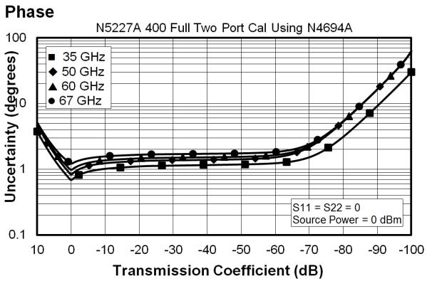
11 Transmission Uncertainty, All Options Reflection Uncertainty, All Options 11
12 Table 4b. N5227A with N4694A 2-Port Electronic Calibration Module Description Specification (db) 10 MHz to 50 MHz 50 MHz to 2 GHz 2 GHz to 20 GHz 20 GHz to 30 GHz 30 GHz to 40 GHz 40 GHz to 50 GHz 50 GHz to 60 GHz 60 GHz to 67 GHz Directivity Source Match Load Match Reflection Tracking Mag ±0.050 ±0.040 ±0.040 ±0.050 ±0.060 ±0.070 ±0.080 ±0.090 Phase ( ) ±0.330 ±0.264 ±0.264 ±0.330 ±0.396 ±0.462 ±0.528 ±0.594 Transmission Tracking Mag ±0.146 ±0.059 ±0.057 ±0.072 ±0.087 ±0.104 ±0.114 ±0.144 Phase ( ) ±0.966 ±0.392 ±0.378 ±0.473 ±0.576 ±0.688 ±0.754 ±


13 Transmission Uncertainty, All Options Reflection Uncertainty, All Options 13
14 Uncorrected System Performance Specifications apply to following conditions: Over environmental temperature of 25 C ±5 C, with less than 1 C variation from the calibration temperature. Cable loss not included in Transmission Tracking. Crosstalk measurement conditions: normalized to a thru, measured with shorts on all ports, 10 Hz IF bandwidth, averaging factor of 8, alternate mode, source power set to the specified maximum power. Table 5a. Error Terms (db), All Ports, All Options - Specifications Directivity Source Match Load Match Transmission Tracking Reflection Tracking Crosstalk 10 MHz to 50 MHz MHz to 500 MHz MHz to 2 GHz GHz to 3.2 GHz GHz to 10 GHz GHz to 16 GHz GHz to 20 GHz GHz to 26.5 GHz GHz to 50 GHz GHz to 60 GHz GHz to 67 GHz GHz to 70 GHz
15 Table 5b. Error Terms (db), All Ports, All Options - Typical Directivity Source Match Load Match Transmission Tracking Reflection Tracking Crosstalk 10 MHz to 50 MHz / / MHz to 200 MHz / / MHz to 500 MHz / / MHz to 2 GHz / / GHz to 3.2 GHz / / GHz to 10 GHz / / GHz to 13.5 GHz / / GHz to 16 GHz / / GHz to 20 GHz / / GHz to 26.5 GHz / / GHz to 43.5 GHz / / GHz to 50 GHz / / GHz to 60 GHz / / GHz to 67 GHz / / GHz to 70 GHz / /
16 Test Port Output Table 6. Frequency Information, All Options Description Specification Typical N5227A Frequency Range 10 MHz to 67 GHz 67 GHz to 70 GHz Frequency Resolution 1 Hz -- Frequency Accuracy +/- 1 ppm -- Frequency Stability -- +/-0.05 ppm, -10 to 70 C1 +/-0.1 ppm/yr maximum2 1 Assumes no variation in time. 2 Assumes no variation in temperature. Table 7a. Maximum Leveled Power (dbm) - Specification Description Option 200, 400 Option 201, 401 Option 219, 419 Port 1, Port 3 Port 2, Port 4 Port 1, Port 3 Port 2, Port 4 Port 1, Port 3 Port 2, Port 4 10 MHz to 50 MHz MHz to 2 GHz GHz to 3.2 GHz GHz to 10 GHz GHz to 13.5 GHz GHz to 16 GHz GHz to 19 GHz GHz to 24 GHz GHz to 26.5 GHz GHz to 30 GHz GHz to 32 GHz GHz to 35 GHz GHz to 40 GHz GHz to 50 GHz GHz to 64 GHz GHz to 67 GHz
17 Table 7b. Maximum Leveled Power (dbm) - Typical Description Option 200, 400 Option 201, 401 Option 219, 419 Port 1, Port 3 Port 2, Port 4 Port 1, Port 3 Port 2, Port 4 Port 1, Port 3 Port 2, Port 4 10 MHz to 50 MHz MHz to 500 MHz MHz to 1 GHz GHz to 2 GHz GHz to 3.2 GHz GHz to 10 GHz GHz to 13.5 GHz GHz to 16 GHz GHz to 19 GHz GHz to 20 GHz GHz to 24 GHz GHz to 30 GHz GHz to 32 GHz GHz to 35 GHz GHz to 40 GHz GHz to 43.5 GHz GHz to 50 GHz GHz to 60 GHz GHz to 64 GHz GHz to 67 GHz GHz to 70 GHz
18 Table 8. Power Level Accuracy (db), All Options Description Specification Typical 10 MHz to 50 MHz +/ / MHz to 1 GHz +/ / GHz to 3.2 GHz +/ / GHz to 20 GHz +/ / GHz to 26.5 GHz +/ / GHz to 40 GHz +/ / GHz to 43.5 GHz +/ / GHz to 50 GHz +/ / GHz to 60 GHz +/ / GHz to 67 GHz +/ / GHz to 70 GHz -- +/- 1.0 Table 9a. Power Level Linearity (db), All Options - Specification Description Specification Port 1 or dBm P<-20dBm Port 1 or dBm P<-15dBm Port 1 or 3 1 P -15dBm 10 MHz to 50 MHz +/-2.5 +/-1.5 +/ MHz to 67 GHz +/-1.5 +/-1.5 +/ Either port can be used as the source port. Table 9b. Power Level Linearity (db), All Options - Specification Description Specification Port 2 or dBm P<-20dBm Port 2 or dBm P<-15dBm Port 2 or 4 1 P -15dBm 10 MHz to 50 MHz +/-3.5 +/-1.5 +/ MHz to 500 MHz +/-2.5 +/-1.5 +/ MHz to 3.2 GHz +/-2.5 +/-1.5 +/ GHz to 67 GHz +/-1.5 +/-1.5 +/ Either port can be used as the source port. 18
19 Table 10a. Power Sweep Range (db) - Specification Description Option 200, 400 Option 201, 401 Option 219, 419 Port 1, Port 3 Port 2, Port 4 Port 1, Port 3 Port 2, Port 4 Port 1, Port 3 Port 2, Port 4 10 MHz to 50 MHz MHz to 2 GHz GHz to 3.2 GHz GHz to 10 GHz GHz to 13.5 GHz GHz to 16 GHz GHz to 19 GHz GHz to 24 GHz GHz to 26.5 GHz GHz to 30 GHz GHz to 32 GHz GHz to 35 GHz GHz to 40 GHz GHz to 50 GHz GHz to 64 GHz GHz to 67 GHz
20 Table 10b. Power Sweep Range (db) - Typical Description Option 200, 400 Option 201, 401 Option 219, 419 Port 1, Port 3 Port 2, Port 4 Port 1, Port 3 Port 2, Port 4 Port 1, Port 3 Port 2, Port 4 10 MHz to 50 MHz MHz to 500 MHz MHz to 1 GHz GHz to 2 GHz GHz to 3.2 GHz GHz to 10 GHz GHz to 13.5 GHz GHz to 16 GHz GHz to 19 GHz GHz to 20 GHz GHz to 24 GHz GHz to 30 GHz GHz to 32 GHz GHz to 35 GHz GHz to 40 GHz GHz to 43.5 GHz GHz to 50 GHz GHz to 60 GHz GHz to 64 GHz GHz to 67 GHz GHz to 70 GHz Table 11. Nominal (Preset) Power (dbm) Description Option 200, 201, 400, 401 Option 219, 419 Preset Power
21 Table 12. Power Resolution and Maximum/Minimum Settable Power, All Models and Options Description Specification (db) Typical (dbm) Power Resolution Maximum Settable Power Minimum Settable Power Option 200, 201, 400, 401 Option 219, Table nd and 3 rd Harmonics at Max Specified Power (dbc) All Options - Typical Listed frequency is harmonic frequency; test at max specified power Description N5227A 20 MHz to 4 GHz GHz to 24 GHz GHz to 27 GHz GHz to 40.5 GHz GHz to 67 GHz GHz to 70 GHz -60 Table 14. Non-Harmonic Spurs at Nominal Power (dbc), All Options - Typical Offset frequency = 30 khz to 5 MHz Description Based on 8kHz offset Frac-N Based on 100kHz offset Frac-N 10 MHz to 500 MHz MHz to 2 GHz GHz to 4 GHz GHz to 8 GHz GHz to 16 GHz GHz to 32 GHz GHz to 64 GHz GHz to 70 GHz
22 Table 15. Phase Noise (dbc/hz), All Options - Typical Description 1 khz Offset 10 khz Offset 100 khz Offset 1 MHz Offset 10 MHz to 50 MHz MHz to 1 GHz GHz to 2 GHz GHz to 4 GHz GHz to 8 GHz GHz to 16 GHz GHz to 32 GHz GHz to 64 GHz GHz to 70 GHz
23 Test Port Input Table 16. Test Port Noise Floor 10 Hz IFBW, All Options Total average (rms) noise power calculated as the mean value of a linear magnitude trace expressed in dbm. May typically be degraded at particular frequencies below 500 MHz due to spurious receiver residuals. Description Specification Typical 10 MHz to 50 MHz MHz to 100 MHz MHz to 500 MHz MHz to 1 GHz GHz to 10 GHz GHz to 13.5 GHz GHz to 24 GHz GHz to 26.5 GHz GHz to 35 GHz GHz to 40 GHz GHz to 50 GHz GHz to 60 GHz GHz to 67 GHz GHz to 70 GHz
24 Table 17. Direct Receiver Access Input Noise Floor (dbm) Total average (rms) noise power calculated as the mean value of a linear magnitude trace expressed in dbm. May typically be degraded at particular frequencies below 500 MHz due to spurious receiver residuals. Description Specification Typical Options 201, 219, 401, 419 Options 201, 219, 401, MHz to 50 MHz MHz to 100 MHz MHz to 500 MHz MHz to 1 GHz GHz to 2 GHz GHz to 10 GHz GHz to 13.5 GHz GHz to 24 GHz GHz to 26.5 GHz GHz to 30 GHz GHz to 35 GHz GHz to 40 GHz GHz to 45 GHz GHz to 50 GHz GHz to 67 GHz GHz to 70 GHz
25 Table 18a. 0.1 db Receiver Compression at Test Port (dbm), Option 201, 219, 401, Typical Description N5227A 10 MHz to 100 MHz MHz to 30 GHz GHz to 67 GHz 11 Table 18b. Receiver Compression at Test Port Power - Specification Description Test Port Power (dbm) Receiver Compression Option 200, 400 Option 201, 401 Option 219, 419 Magnitude (db) Phase (degrees) 10 MHz to 500 MHz MHz to 2 GHz GHz to 3.2 GHz GHz to 10 GHz GHz to 13.5 GHz GHz to 16 GHz GHz to 20 GHz GHz to 24 GHz GHz to 30 GHz GHz to 35 GHz GHz to 40 GHz GHz to 67 GHz Test port receiver compression at specified input levels below 500 MHz due to coupler roll off in this frequency range. 25
26 Table 19. N5227A Trace Noise Magnitude (db rms) Ratioed measurement, nominal power at test port. Description Specification Typical 1 khz IFBW 1 khz IFBW 100 khz IFBW 600 khz IFBW 10 MHz to 50 MHz MHz to 100 MHz MHz to 500 MHz MHz to 1 GHz GHz to 26.5 GHz GHz to 50 GHz GHz to 67 GHz GHz to 70 GHz Table 20. N5227A Trace Noise Phase (deg rms) Ratioed measurement, nominal power at test port. Description Specification Typical 1 khz IFBW 1 khz IFBW 100 khz IFBW 600 khz IFBW 10 MHz to 50 MHz MHz to 100 MHz MHz to 500 MHz MHz to 1 GHz GHz to 26.5 GHz GHz to 43.5 GHz GHz to 50 GHz GHz to 67 GHz GHz to 70 GHz Table 21. Reference Level Magnitude, All Models and Options - Specification Description Magnitude (db) Phase (degrees) Range +/ /- 500 Resolution
27 Table 22. Stability, All Options - Typical Description Magnitude (db/ C) Phase ( / C) 10 MHz to 50 MHz MHz to 3.2 GHz GHz to 20 GHz GHz to 32 GHz GHz to 35 GHz GHz to 50 GHz GHz to 67 GHz GHz to 70 GHz Table 23. Damage Input Level, All Options Description RF (dbm) DC (V) N5227A


28 Dynamic Accuracy Dynamic accuracy is verified with the following measurements: Compression over frequency IF linearity at a single frequency of GHz using a reference level of -20 dbm for an input power range of 0 to -60 dbm. For values below -60 dbm, refer to VNA Receiver Dynamic Accuracy Specifications and Uncertainties Table 24. N5227A Dynamic Accuracy N5227A Dynamic Accuracy, 10 MHz - Specification N5227A Dynamic Accuracy, 50 MHz - Specification N5227A Dynamic Accuracy, 500 MHz - Specification 28


29 N5227A Dynamic Accuracy, 1 GHz - Specification N5227A Dynamic Accuracy, 2 GHz - Specification N5227A Dynamic Accuracy, 20 GHz - Specification 29


30 N5227A Dynamic Accuracy, 26.5 GHz - Specification N5227A Dynamic Accuracy, 35 GHz - Specification N5227A Dynamic Accuracy, 40 GHz - Specification 30


31 N5227A Dynamic Accuracy, 50 GHz - Specification N5227A Dynamic Accuracy, 60 GHz - Specification N5227A Dynamic Accuracy, 67 GHz - Specification 31
/[360 Aperture (Hz)] Depending on the aperture and")
32 Table 25. Group Delay - Typical Group delay is computed by measuring the phase change within a specified frequency step (determined by the frequency span and the number of points per sweep). In general, the following formula can be used to determine the accuracy, in seconds, of specific group delay measurement: ±Phase Accuracy (deg)/[360 Aperture (Hz)] Depending on the aperture and device length, the phase accuracy used is either incremental phase accuracy or worstcase phase accuracy Description Typical Performance Aperture (selectable) (frequency span)/(number of points -1) Maximum Aperture Range Maximum Delay 20% of frequency span 0.5 x (1/minimum aperture) Limited to measuring no more than 180 of phase change within the minimum aperture.) The following graph shows characteristic group delay accuracy with full 2-port calibration and a 10 Hz IF bandwidth. Insertion loss is assumed to be < 2 db and electrical length to be ten meters. For any Sij Group Delay measurement, Sii = 0, Sij = 1, Sji = 0, Skl = 0 for all kl ij 32
33 General Information Miscellaneous Information Front Panel Rear Panel Environment and Dimensions Table 26. Miscellaneous Information Description System IF Bandwidth Range CPU LXI Supplemental Information 1 Hz to 15 MHz, nominal Intel 2.0 GHz Core i7. Note: Some instruments may have a different CPU. For the latest information on CPUs and associated hard drives, visit: Class C Table 27. Front Panel Information, All Options Description Typical Performance RF Connectors Type Center Pin Recession 1.85 mm (male), 50 ohm, (nominal) in. (characteristic) USB 2.0 Ports - Master (4 ports) Standard Compatible with USB 2.0 Connector USB Type-A female Display Size Refresh Rate Pixels 26.3 cm (10.4 in) diagonal color active matrix LCD; 1024 (horizontal) X 768 (vertical) resolution Vertical 60 Hz; Horizontal khz Any of the following would cause a display to be considered faulty: A complete row or column consists of stuck or dark pixels. More than six stuck on pixels (but not more than three green) or more than 0.002% of the total pixels are within the LCD specifications. More than twelve dark pixels (but no more than seven of the same color) or more than 0.004% of the total pixels are within the LCD specifications. Two or more consecutive "stuck on" pixels or three or more consecutive "dark" pixel (but no more than one set of two consecutive dark pixels) Stuck on dark pixels are less than 6.5 mm apart (excluding consecutive pixels) 33
34 Table 27. (Continued) Front Panel Information, All Options Description Typical Performance Display Range Magnitude Phase Polar +/-2500 db (at 500 db/div), max +/-2500 (at 500 db/div), max 10 punits, min 10,000 Units, max Display Resolution Magnitude Phase db/div, min 0.01 /div, min Marker Resolution Magnitude Phase Polar db, min 0.01, min 10 punit, min Table 28. Rear Panel Information, All Options Description Typical Performance 10 MHz Reference In Connector Input Frequency Input Level BNC, female 10 MHz ± 10 ppm -15 dbm to +20 dbm Input Impedance 200, nom. 10 MHz Reference Out Connector Output Frequency Signal Type BNC, female 10 MHz ± 1 ppm Sine Wave Output Level +10 dbm ± 4 db into 50 Output Impedance 50, nominal Harmonics <-40 dbc, typical 34
35 Table 28. (Continued) Rear Panel Information, All Options Description Typical Performance External IF Inputs Function Connectors Input Frequency Normal IF path Narrowband IF path Allows use of external IF signals from remote mixers, bypassing the PNA's first converters SMA (female); A, B, C, D, R (4-port); A, B, R1, R2 (2-port) RF < 53 MHz: IF = KHz RF >= 53 MHz: IF = MHz IF = MHz Input Impedance 50 RF Damage Level DC Damage Level 0.1 db Compression Point Normal IF path Narrowband IF path +23 dbm 5.5 VDC -9.0 dbm at MHz -17 dbm at MHz Pulse Inputs (IF Gates) Function Connectors Input Impedance Minimum Pulse Width, Source Modulators Minimum Pulse Width, Receiver Gates DC Damage Level Drive Voltage Internal receiver gates used for point-in-pulse and pulse-profile measurements 15-pin mini D-sub 1 K Ohm 33 ns 20 ns 5.5 VDC 0 V (off), +3.3 V (on), nominal RF Pulse Modulator Input (Source Modulator) On/Off Ratio 10 MHz to 3.2 GHz GHz to 67 GHz -80 Pulse Period Minimum Maximum 33 ns 70 s 35
36 Table 28. (Continued) Rear Panel Information, All Options Description Typical Performance Pulse Outputs Voltage (TTL) High: 3.3V to 3.5V Low: <1V Impedance 50 Ohm External Test Set Driver Function Connections RF Output Frequency Range LO Output Frequency Range Used for driving remote mixers 3.5 mm (female) 3.2 GHz to 19 GHz 1.76 GHz to 26.5 GHz Rear Panel LO Power 1 Upper Limit, Typical (dbm) Lower Limit, Typical (dbm) 1.7 GHz to 16 GHz GHz to 21 GHz GHz to 26.5 GHz 4-5 Rear Panel RF1/RF2 Power Maximum Output Power, Typical (dbm) 3.2 GHz to 5 GHz +3 5 GHz to 19 GHz +8 VGA Video Output Connector Devices Supported 15-pin mini D-Sub; Drives VGA compatible monitors Resolutions Flat Panel (TFT) 1024 X 768, 800 X 600, 640 X 480 Flat Panel (DSTN) 800 X 600, 640 X 480 CRT Monitor 1280 X 1024, 1024 X 768, 800 X 600, 640 X 480 Simultaneous operation of the internal and external displays is allowed, but with 640 X 480 resolution only. If you change resolution, you can only view the external display (internal display will "white out"). 1 LO output available in full analyzer s frequency range. The power is tested only from 3.2 GHz to 26.5 GHz. 36
37 Table 28. (Continued) Rear Panel Information, All Options Description Typical Performance Bias Tee Inputs Connectors BNC(f) for ports 1, 2, 3 and 4 Fuse Maximum Bias Current Maximum Bias Voltage Trigger Inputs/Outputs Test Set IO Power IO Handler IO GPIB Parallel Port (LPT1) USB Ports LAN 500 ma, bi-pin style +/-200 ma with no degradation of RF specifications +/-40 VDC BNC(f), TTL/CMOS compatible 25-pin D-Sub connector, available for external test set control. 9-pin D-Sub, female; analog and digital IO 36-pin parallel I/O port; all input/output signals are default set to negative logic; can be reset to positive logic via GPIB command. Two ports - dedicated controller and dedicated talker/listener. 24-pin D-sub (Type D-24), female; compatible with IEEE pin D-Sub miniature connector, female; provides connection to printers or any other parallel port peripherals Four ports on front panel (all Host) and five ports (four Host and one Device) on rear panel. Type A configuration (eight Host) and Type B configuration (one Device), USB 2.0 compatible. The total current limit for all rear panel USB ports is 2.0 amps. The total current limit for all front panel USB is 0.9 amps. 10/100BaseT Ethernet, 8-pin configuration; auto selects between the two data rates Line Power Frequency, Voltage 50/60/400 Hz for 100 to 120 VAC 50/60 Hz for 220 to 240 VAC Power supply is auto switching Max 450 watts 37
38 Table 29. Analyzer Dimensions and Weight All models are shipped with handles. Cabinet Dimensions Metric (mm) Imperial (inches) Height Without bottom feet: 1 EIA RU = With bottom feet Width Without handles or rack-mount flanges With handles, without rack-mount flanges With handles and rack-mount flanges Depth Without front and rear panel hardware With front and rear panel hardware, handles Electronics Industry Association rack units. 1 RU = 1.75 in. See detailed PNA dimension drawings at: Weight (nominal) Net Shipping 2-port models (Option 200, 201, 219) 42.2 kg (93 lb) 57.6 kg (127 lb) 4-port models (Option 400, 401, 419) 44.9 kg (99 lb) 60.3 kg (133 lb) Regulatory and Environmental Information For Regulatory and Environmental information, refer to the PNA Series Installation and Quick Start Guide, located online at 38
39 Measurement Throughput Summary Typical Cycle Time for Measurement Completion Cycle Time vs. IF Bandwidth Cycle Time vs. Number of Points Data Transfer Time Cycle time Includes sweep time, retrace time and band-crossing time. Analyzer display turned off with DISPLAY:ENABLE OFF. Add 21 ms for display on. Data for one trace (S11) measurement. Table 30. Typical Cycle Time (ms) for Measurement Completion, All Models and Options Sweep Range 9 GHz to 10 GHz 10 GHz to 20 GHz IF Bandwidth 600 khz 10 khz 1 khz 600 khz 10 khz 1 khz Number of Points Uncorrected Port cal Uncorrected Port cal Uncorrected Port cal Uncorrected Port cal Uncorrected Port cal Uncorrected Port cal
40 Table 31. Typical Cycle Time (ms) for Full-Span Measurement Completion 10 MHz to 67 GHz Number of Points IF Bandwidth khz 10 khz 1 khz Uncorrected Port cal Uncorrected Port cal Uncorrected Port cal Table 32. Cycle Time vs. IF Bandwidth - Typical Applies to the Preset condition (201 points, correction off) except for the following changes: CF = 10 GHz Span = 100 MHz Display off (add 21 ms for display on) Cycle time includes sweep and retrace time. Description N5227A IF Bandwidth (Hz) Cycle Time (ms) Trace Noise Magnitude (db rms) 600, , , , , ,
41 Table 33. Cycle Time vs. Number of Points - Typical Applies to the Preset condition (correction off) except for the following changes: CF = 10 GHz Span = 100 MHz Display off (add 21 ms for display on) Cycle time includes sweep and retrace time. Description IF Bandwidth (Hz) Number of Points 1,000 10,000 30, , , , , ,
42 Table 34. Data Transfer Time (ms) - Typical Measured with the analyzer display off. Values will increase slightly if the analyzer display is on. Description Number of Points ,001 32,001 SCPI over GPIB (Program executed on external PC 2 ) 32-bit floating point bit floating point ASCII SCPI over SICL/LAN or TCP/IP Socket 1 (Program executed in the analyzer) 32-bit floating point <1 <1 < bit floating point <1 <1 < ASCII COM 1 (Program executed in the analyzer) 32-bit floating point <1 <1 <1 <1 <1 Variant type <1 < DCOM over LAN 1 (Program executed on external PC) 32-bit floating point <1 <1 < Variant type < Values are for real and imaginary pairs, with the analyzer display off, using Gigabit Ethernet. Note: Specifications for Recall & Sweep Speed are not provided for the N522xA analyzers. 42
 - Typical (RCVR A, B, C, D IN) @ 0.")
43 Specifications: Front-Panel Jumpers The following options have front-panel jumpers for each port: 201, 219, 401, 419 Measurement Receiver Inputs Port 1 Reference Receiver Inputs and Reference Source Outputs Port 2, 3, 4 Reference Receiver Inputs and Reference Source Outputs Source Outputs Coupler Inputs Damage Level Table 35. Measurement Receiver Inputs (dbm) - Typical (RCVR A, B, C, D 0.1dB Typical Compression Description N5227A 10 MHz to 500 MHz MHz to 3.2 GHz GHz to 26.5 GHz GHz to 50 GHz GHz to 64 GHz GHz to 67 GHz GHz to 70 GHz -2 43
44 Table 36. Port 1 Reference Receiver Inputs and Reference Source Outputs (dbm) - Typical (RCVR R1 IN, REF 1 SOURCE Max Specified Output Power Description Option 201, 401 Option 219, MHz to 50 MHz MHz to 500 MHz MHz to 1 GHz GHz to 2 GHz GHz to 3.2 GHz GHz to 10 GHz GHz to 16 GHz GHz to 26.5 GHz GHz to 30 GHz GHz to 32 GHz GHz to 35 GHz GHz to 40 GHz GHz to 70 GHz
45 Table 37. Port 2, 3, 4 Reference Receiver Inputs and Reference Source Outputs (dbm) - Typical (RCVR R2 IN, RCVR R3 IN, RCVR R4 IN, REF 2 SOURCE OUT, REF 3 SOURCE OUT, REF 4 SOURCE Max Specified Output Power Description Option 201, 401 Option 401 Option 219, 419 Option 419 RCVR R2 IN, RCVR R4 IN, REF 2 SOURCE OUT, REF 4 SOURCE OUT RCVR R3 IN, REF 3 SOURCE OUT RCVR R2 IN, RCVR R4 IN, REF 2 SOURCE OUT, REF 4 SOURCE OUT RCVR R3 IN, REF 3 SOURCE OUT 10 MHz to 50 MHz MHz to 500 MHz MHz to 1 GHz GHz to 2 GHz GHz to 3.2 GHz GHz to 10 GHz GHz to 16 GHz GHz to 26.5 GHz GHz to 30 GHz GHz to 32 GHz GHz to 35 GHz GHz to 40 GHz GHz to 50 GHz GHz to 60 GHz GHz to 64 GHz GHz to 67 GHz GHz to 70 GHz
46 Table 38. Source Outputs (dbm) - Typical (PORT 1 SOURCE OUT, PORT 2 SOURCE OUT, PORT 3 SOURCE OUT, PORT 4 SOURCE Max Specified Output Power Description Option 201, 401 Option 219, 419 PORT 1 SOURCE OUT PORT 2 SOURCE OUT PORT 1 SOURCE OUT PORT 2 SOURCE OUT PORT 3 SOURCE OUT PORT 4 SOURCE OUT PORT 3 SOURCE OUT PORT 4 SOURCE OUT 10 MHz to 50 MHz MHz to 1 GHz GHz to 2 GHz GHz to 3.2 GHz GHz to 10 GHz GHz to 16 GHz GHz to 26.5 GHz GHz to 30 GHz GHz to 32 GHz GHz to 35 GHz GHz to 40 GHz GHz to 60 GHz GHz to 64 GHz GHz to 70 GHz
47 Table 39. Coupler Inputs (db) - Typical (PORT 1, 2, 3, 4 CPLR THRU) Insertion Loss of Coupler Thru Description Option 201, 401 Option 219, MHz to 50 MHz MHz to 500 MHz MHz to 1 GHz GHz to 2 GHz GHz to 3.2 GHz GHz to 10 GHz GHz to 16 GHz GHz to 26.5 GHz GHz to 35 GHz GHz to 40 GHz GHz to 50 GHz GHz to 60 GHz GHz to 64 GHz GHz to 67 GHz GHz to 70 GHz Table 40 Damage Level, All Options - Typical Description RF (dbm) DC (V) RCVR A, B, C, D IN 15 7 RCVR R1, R2, R3, R4 IN 15 7 REF 1 SOURCE OUT 15 7 REF 2, 3, 4 SOURCE OUT 30 7 PORT 1, 2, 3, 4 SOURCE OUT 27 7 PORT 1, 2, 3, 4 CPLR THRU PORT 1, 2, 3, 4 CPLR ARM
 N5227A Option 201 To base model, adds front-panel jumpers and R1 receiver")
48 Test Set Block Diagrams NOTE: For best readability, use a color printer for printing the following graphics. Legend N5227A Option 200 (2-port base model) N5227A Option 201 To base model, adds front-panel jumpers and R1 receiver switch 48
, and bias-tees.")
49 N5227A Option 219 To base model, adds front-panel jumpers, R1 receiver switch, source and receiver attenuators (extended power range), and bias-tees. N5227A Option 400 (4-port base model) 49

, and bias-tees.")
50 N5227A Option 401 To base model, adds front-panel jumpers and R1 receiver switch N5227A Option 419 To base model, adds front-panel jumpers, R1 receiver switch, source and receiver attenuators (extended power range), and bias-tees. 50
51 Receiver Block Diagram A Narrowband filter IF gate Anti-alias filter ADC Digital FIR IF filter External IF input 51
 is an open standard that extends the AdvancedTCA for general purpose and semiconductor test.")
52 Agilent Updates Get the latest information on the products and applications you select.. AdvancedTCA Extensions for Instrumentation and Test (AXIe) is an open standard that extends the AdvancedTCA for general purpose and semiconductor test. Agilent is a founding member of the AXIe consortium. LAN extensions for Instruments puts the power of Ethernet and the Web inside your test systems. Agilent is a founding member of the LXI consortium. PCI extensions for Instrumentation (PXI) modular instrumentation delivers a rugged, PC-based high-performance measurement and automation system. Agilent Channel Partners Get the best of both worlds: Agilent s measurement expertise and product breadth, combined with channel partner convenience. For more information on Agilent Technologies products, applications or services, please contact your local Agilent office. The complete list is available at: Americas Canada Brazil Mexico United States Asia Pacific Australia China Hong Kong India Japan Korea Malaysia Singapore Taiwan Other AP Countries Europe & Middle East Belgium Denmark Finland France Germany Ireland Israel Italy Netherlands Spain Sweden United Kingdom For other unlisted countries: (877) (11) (800) (421) (65) (0) (0) * *0.125 /minute 49 (0) / (0) (91) (0) Product specifications and descriptions in this document subject to change without notice. Agilent Technologies, Inc. Published in USA, September 2, 2013 Supersedes: July 25, 2013 N
Advanced Test Equipment Rentals ATEC (2832)
") Established 1981 Advanced Test Equipment Rentals www.atecorp.com 800-404-ATEC (2832) Agilent 2-Port and 4-Port PNA-X Network Analyzer N5249A - 10 MHz to 8.5 GHz N5241A - 10 MHz to 13.5 GHz N5242A - 10
Established 1981 Advanced Test Equipment Rentals www.atecorp.com 800-404-ATEC (2832) Agilent 2-Port and 4-Port PNA-X Network Analyzer N5249A - 10 MHz to 8.5 GHz N5241A - 10 MHz to 13.5 GHz N5242A - 10
Agilent 2-Port and 4-Port PNA Network Analyzer
 Agilent 2-Port and 4-Port PNA Network Analyzer N5221A 10 MHz to 13.5 GHz N5222A 10 MHz to 26.5 GHz Data Sheet and Technical Specifications Documentation Warranty THE MATERIAL CONTAINED IN THIS DOCUMENT
Agilent 2-Port and 4-Port PNA Network Analyzer
 Agilent 2-Port and 4-Port PNA Network Analyzer N5224A 10 MHz to 43.5 GHz N5225A 10 MHz to 50 GHz Data Sheet and Technical Specifications Documentation Warranty THE MATERIAL CONTAINED IN THIS DOCUMENT IS
Agilent 2-Port and 4-Port PNA-X Network Analyzer. N5241A - 10 MHz to 13.5 GHz N5242A - 10 MHz to 26.5 GHz Data Sheet and Technical Specifications
 Agilent 2-Port and 4-Port PNA-X Network Analyzer N5241A - 10 MHz to 13.5 GHz N5242A - 10 MHz to 26.5 GHz Data Sheet and Technical Specifications Documentation Warranty THE MATERIAL CONTAINED IN THIS DOCUMENT
Keysight 2-Port and 4-Port PNA Network Analyzer
 Keysight 2-Port and 4-Port PNA Network Analyzer N5227A 10 MHz to 67 GHz Data Sheet and Technical Specifications Documentation Warranty THE MATERIAL CONTAINED IN THIS DOCUMENT IS PROVIDED "AS IS," AND IS
Keysight 2-Port and 4-Port PNA Network Analyzer
 Keysight 2-Port and 4-Port PNA Network Analyzer N5227A 10 MHz to 67 GHz Data Sheet and Technical Specifications for Option 210 and 410 Documentation Warranty THE MATERIAL CONTAINED IN THIS DOCUMENT IS
Keysight 2-Port and 4-Port PNA Network Analyzer
 Keysight 2-Port and 4-Port PNA Network Analyzer N5224A 10 MHz to 43.5 GHz N5225A 10 MHz to 50 GHz Data Sheet and Technical Specifications Documentation Warranty THE MATERIAL CONTAINED IN THIS DOCUMENT
Keysight 2-Port and 4-Port PNA Network Analyzer
 Keysight 2-Port and 4-Port PNA Network Analyzer N5221A 10 MHz to 13.5 GHz N5222A 10 MHz to 26.5 GHz Data Sheet and Technical Specifications Documentation Warranty THE MATERIAL CONTAINED IN THIS DOCUMENT
Keysight 2-Port and 4-Port PNA Network Analyzer
 Keysight 2-Port and 4-Port PNA Network Analyzer N5221A 10 MHz to 13.5 GHz N5222A 10 MHz to 26.5 GHz Data Sheet and Technical Specifications Documentation Warranty THE MATERIAL CONTAINED IN THIS DOCUMENT
Keysight 2-Port and 4-Port PNA Network Analyzer
 Keysight 2-Port and 4-Port PNA Network Analyzer N5224B 10 MHz to 43.5 GHz N5225B 10 MHz to 50 GHz Data Sheet and Technical Specifications Documentation Warranty THE MATERIAL CONTAINED IN THIS DOCUMENT
Agilent 2-Port and 4-Port PNA-L Network Analyzer N5239A 300 khz to 8.5 GHz N5231A 300 khz to 13.5 GHz N5232A 300 khz to 20 GHz
 Agilent 2-Port and 4-Port PNA-L Network Analyzer N5239A 300 khz to 8.5 GHz N5231A 300 khz to 13.5 GHz N5232A 300 khz to 20 GHz Data Sheet and Technical Specifications Documentation Warranty THE MATERIAL
Keysight 2-Port and 4-Port PNA Network Analyzer N5221B 10 MHz to 13.5 GHz N5222B 10 MHz to 26.5 GHz
 Keysight 2-Port and 4-Port PNA Network Analyzer N5221B 10 MHz to 13.5 GHz N5222B 10 MHz to 26.5 GHz Data Sheet and Technical Specifications Documentation Warranty THE MATERIAL CONTAINED IN THIS DOCUMENT
Agilent 2-Port and 4-Port PNA-X Network Analyzer
 Agilent 2-Port and 4-Port PNA-X Network Analyzer N5244A - MHz to 43.5 GHz N5245A - MHz to 5. GHz with Option H29 Data Sheet and Technical Specifications Documentation Warranty THE MATERIAL CONTAINED IN
Keysight 2-Port and 4-Port PNA Network Analyzer
 Keysight 2-Port and 4-Port PNA Network Analyzer N5221A 10 MHz to 13.5 GHz N5222A 10 MHz to 26.5 GHz Data Sheet and Technical Specifications for Option 210 and 410 Documentation Warranty THE MATERIAL CONTAINED
Keysight 2-Port and 4-Port PNA-L Network Analyzer
 Keysight 2-Port and 4-Port PNA-L Network Analyzer N5239A 300 khz to 8.5 GHz N523A 300 khz to 3.5 GHz N5232A 300 khz to 20 GHz Data Sheet and Technical Specifications Documentation Warranty THE MATERIAL
Keysight 2-Port and 4-Port PNA Network Analyzer
 Keysight 2-Port and 4-Port PNA Network Analyzer N5227A 10 MHz to 67 GHz Data Sheet and Technical Specifications for Option 210 and 410 Documentation Warranty THE MATERIAL CONTAINED IN THIS DOCUMENT IS
Agilent 4-Port PNA-L Network Analyzer. N5230A/C Options: 140/145/146/240/245/246 Technical Specifications
 Agilent 4-Port PNA-L Network Analyzer N5230A/C Options: 140/145/146/240/245/246 Technical Specifications Documentation Warranty THE MATERIAL CONTAINED IN THIS DOCUMENT IS PROVIDED "AS IS," AND IS SUBJECT
Keysight 2-Port and 4-Port PNA Network Analyzer
 Keysight 2-Port and 4-Port PNA Network Analyzer N5227A 10 MHz to 67 Data Sheet and Technical Specifications Documentation Warranty THE MATERIAL CONTAINED IN THIS DOCUMENT IS PROVIDED "AS IS," AND IS SUBJECT
Keysight 2-Port and 4-Port PNA-X Network Analyzer
 Keysight 2-Port and 4-Port PNA-X Network Analyzer N5249A - 0 MHz to 8.5 GHz N524A - 0 MHz to 3.5 GHz N5242A - 0 MHz to 26.5 GHz Data Sheet and Technical Specifications Documentation Warranty THE MATERIAL
Keysight 2-Port and 4-Port PNA-X Network Analyzer
 Keysight 2-Port and 4-Port PNA-X Network Analyzer N5249A - 0 MHz to 8.5 GHz N524A - 0 MHz to 3.5 GHz N5242A - 0 MHz to 26.5 GHz Data Sheet and Technical Specifications Documentation Warranty THE MATERIAL
Keysight 2-Port and 4-Port Broadband Network Analyzer
 Keysight 2-Port and 4-Port Broadband Network Analyzer N5291A 500 Hz to 125 GHz Technical Specifications Documentation Warranty THE MATERIAL CONTAINED IN THIS DOCUMENT IS PROVIDED "AS IS," AND IS SUBJECT
Agilent 4-Port PNA-L Microwave Network Analyzer
 Agilent 4-Port PNA-L Microwave Network Analyzer N523A Options 24 and 245 3 khz to 2 GHz Data Sheet Note: Specification information in this document is also available within the PNA-L network analyzer s
Advanced Test Equipment Rentals ATEC (2832)
") Established 1981 Advanced Test Equipment Rentals www.atecorp.com 800-404-ATEC (2832) Technical Specifications Agilent Technologies PNA Series Network Analyzers E8801A, E8802A, and E8803A Discontinued Product
Established 1981 Advanced Test Equipment Rentals www.atecorp.com 800-404-ATEC (2832) Technical Specifications Agilent Technologies PNA Series Network Analyzers E8801A, E8802A, and E8803A Discontinued Product
Agilent. E5071C ENA Network Analyzer 9 khz to 4.5/6.5/8.5 GHz 100 khz to 4.5/6.5/8.5 GHz (with bias tees) 300 khz to 14/20 GHz (with bias tees)
 300 khz to 14/20 GHz (with bias tees)") Agilent E571C ENA Network Analyzer 9 khz to 4.5/6.5/8.5 GHz khz to 4.5/6.5/8.5 GHz (with bias tees) 3 khz to 14/2 GHz (with bias tees) E592A Configurable Multiport Test Set Data Sheet Table of Contents
Agilent E571C ENA Network Analyzer 9 khz to 4.5/6.5/8.5 GHz khz to 4.5/6.5/8.5 GHz (with bias tees) 3 khz to 14/2 GHz (with bias tees) E592A Configurable Multiport Test Set Data Sheet Table of Contents
Agilent. E5071C ENA Network Analyzer 9 khz to 4.5/6.5/8.5 GHz 100 khz to 4.5/6.5/8.5 GHz (with bias tees) 300 khz to 14/20 GHz (with bias tees)
 300 khz to 14/20 GHz (with bias tees)") Agilent E5071C ENA Network Analyzer 9 khz to 4.5/6.5/8.5 GHz 0 khz to 4.5/6.5/8.5 GHz (with bias tees) 300 khz to 14/20 GHz (with bias tees) E5091A Multiport Test Set E5092A Configurable Multiport Test
Agilent E5071C ENA Network Analyzer 9 khz to 4.5/6.5/8.5 GHz 0 khz to 4.5/6.5/8.5 GHz (with bias tees) 300 khz to 14/20 GHz (with bias tees) E5091A Multiport Test Set E5092A Configurable Multiport Test
Agilent N9342C Handheld Spectrum Analyzer (HSA)
") Agilent N9342C Handheld Spectrum Analyzer (HSA) Data Sheet Field testing just got easier The Agilent N9342C handheld spectrum analyzer (HSA) is more than easy-to-use its measurement performance gives you
Agilent N9342C Handheld Spectrum Analyzer (HSA) Data Sheet Field testing just got easier The Agilent N9342C handheld spectrum analyzer (HSA) is more than easy-to-use its measurement performance gives you
Agilent E5072A ENA Series Network Analyzer
 Agilent E572A ENA Series Network Analyzer 3 khz to 4.5 /8.5 GHz Data Sheet Options This document provides technical specifications for the E572A ENA network analyzer. E572A-245 E572A-285 2-port with configurable
Keysight Technologies E5071C ENA Vector Network Analyzer. E5092A Configurable Multiport Test Set
 Keysight Technologies E5071C ENA Vector Network Analyzer 9 khz to 4.5/6.5/8.5 GHz 100 khz to 4.5/6.5/8.5 GHz (with bias tees) 300 khz to 14/20 GHz (with bias tees) E5092A Configurable Multiport Test Set
Agilent ENA Series 2, 3 and 4 Port RF Network Analyzers E5070A 300 khz to 3 GHz E5071A 300 khz to 8.5 GHz E5091A Multiport Test Set.
 Agilent ENA Series 2, 3 and 4 Port RF Network Analyzers E5070A 300 khz to 3 GHz E5071A 300 khz to 8.5 GHz E5091A Multiport Test Set Data Sheet Definitions All specifications apply over a 5 C to 40 C range
Agilent N9342C Handheld Spectrum Analyzer (HSA)
") Agilent N9342C Handheld Spectrum Analyzer (HSA) 100 khz to 7 GHz (tunable to 9 khz) Data Sheet Field testing just got easier www.agilent.com/find/hsa If you are making measurements in the field, the Agilent
Agilent N9342C Handheld Spectrum Analyzer (HSA) 100 khz to 7 GHz (tunable to 9 khz) Data Sheet Field testing just got easier www.agilent.com/find/hsa If you are making measurements in the field, the Agilent
Agilent. E5071C ENA Network Analyzer 9 khz to 4.5/6.5/8.5 GHz 100 khz to 4.5/6.5/8.5 GHz (with bias tees) 300 khz to 14/20 GHz (with bias tees)
 300 khz to 14/20 GHz (with bias tees)") Agilent E571C ENA Network Analyzer 9 khz to 4.5/6.5/8.5 GHz khz to 4.5/6.5/8.5 GHz (with bias tees) 3 khz to 14/2 GHz (with bias tees) E592A Configurable Multiport Test Set Data Sheet Table of Contents
Agilent E571C ENA Network Analyzer 9 khz to 4.5/6.5/8.5 GHz khz to 4.5/6.5/8.5 GHz (with bias tees) 3 khz to 14/2 GHz (with bias tees) E592A Configurable Multiport Test Set Data Sheet Table of Contents
Agilent. E5071C ENA Network Analyzer 9 khz to 4.5/6.5/8.5 GHz 100 khz to 4.5/6.5/8.5 GHz (with bias tees) 300 khz to 14/20 GHz (with bias tees)
 300 khz to 14/20 GHz (with bias tees)") Agilent E5071C ENA Network Analyzer 9 khz to 4.5/6.5/8.5 GHz 100 khz to 4.5/6.5/8.5 GHz (with bias tees) 300 khz to 14/20 GHz (with bias tees) E5092A Configurable Multiport Test Set Data Sheet Table of
Agilent E5071C ENA Network Analyzer 9 khz to 4.5/6.5/8.5 GHz 100 khz to 4.5/6.5/8.5 GHz (with bias tees) 300 khz to 14/20 GHz (with bias tees) E5092A Configurable Multiport Test Set Data Sheet Table of
Keysight E5063A ENA Series Network Analyzer
 Keysight E5063A ENA Series Network Analyzer 100 khz to 500 M/1.5 G/3 G/4.5 G/6.5 G/8.5 G/14 G/18 GHz Data Sheet 02 Keysight E5063A ENA Series Network Analyzer - Data Sheet Deinitions Speciication (spec.):
Keysight E5063A ENA Series Network Analyzer
 Keysight E5063A ENA Series Network Analyzer 100 khz to 4.5/8.5/18 GHzz Data Sheet Deinitions Specification (spec.): Warranted performance. All speciications apply at 23 ºC (± 5 ºC), unless otherwise stated,
Agilent N9320B RF Spectrum Analyzer
 Agilent N9320B RF Spectrum Analyzer 9 khz to 3.0 GHz Data Sheet Definitions and Conditions The spectrum analyzer will meet its specifications when: It is within its calibration cycle It has been turned
Agilent E5061B Network Analyzer. 100 khz to 1.5 GHz/3 GHz 5 Hz to 3 GHz
 Agilent E5061B Network Analyzer 100 khz to 1.5 GHz/3 GHz 5 Hz to 3 GHz E5061B responds to various measurement needs, - from LF to RF The Agilent E5061B is a member of the industry standard ENA Series network
Agilent E1412A 6.5-Digit High-Accuracy Multimeter C-Size
 Agilent E1412A 6.5-Digit High-Accuracy Multimeter C-Size Data Sheet Features 1-Slot, C-size, message-based DCV, ACV, DCI, ACI, 2/4-wire Ω, frequency, period NULL, MIN/MAX, LIMIT, db, dbm 1000 reading/s
Agilent ENA 2 and 4 Port RF Network Analyzers
 Agilent ENA 2 and 4 Port RF Network Analyzers Data Sheet E5071C-240/440 9 khz to 4.5 GHz E5071C-245/445 0 khz to 4.5 GHz (with bias-tees) E5071C-280/480 9 khz to 8.5 GHz E5071C-285/485 0 khz to 8.5 GHz
Agilent N8973A, N8974A, N8975A NFA Series Noise Figure Analyzers. Data Sheet
 Agilent N8973A, N8974A, N8975A NFA Series Noise Figure Analyzers Data Sheet Specifications Specifications are only valid for the stated operating frequency, and apply over 0 C to +55 C unless otherwise
MXG Analog Signal Generator Express Configurations
 MXG Analog Signal Generator Express Configurations N5181AEP MXG RF Analog (100 khz to 1, 3 or 6 GHz) N5183AEP MXG MW Analog (100 khz to 20 GHz) Technical Overview When you just can t wait, get the same
Keysight Technologies A comparison of Keysight Network Analyzers for Applications < 3 GHz. Selection Guide
 Keysight Technologies A comparison of Keysight Network Analyzers for Applications < 3 GHz Selection Guide N9923A FieldFox RF Vector Network Analyzer, 2 MHz to 4/6 GHz Keysight Technologies, Inc. handheld
Agilent Spectrum Visualizer (ASV) Software. Data Sheet
 Software. Data Sheet") Agilent Spectrum Visualizer (ASV) Software Data Sheet Technical Overview The Agilent spectrum visualizer (ASV) software provides advanced FFT frequency domain analysis for the InfiniiVision and Infiniium
Agilent Spectrum Visualizer (ASV) Software Data Sheet Technical Overview The Agilent spectrum visualizer (ASV) software provides advanced FFT frequency domain analysis for the InfiniiVision and Infiniium
Agilent RF Network Analyzers PNA Series
 Agilent RF Network Analyzers PNA Series Technical Specifications This document describes the performance and features of Agilent Technologies PNA Series RF network analyzers: Agilent E8356A S-parameter
Keysight 8762F Coaxial Switch 75 ohm
 Keysight 8762F Coaxial Switch 75 ohm Technical Overview DC to 4 GHz Exceptional repeatability over 1 million cycle life Excellent isolation The 8762F brings a new standard of performance to 75 ohm coaxial
7 Hints That Every Engineer Should Know When Making Power Measurements with Oscilloscopes.
 7 Hints That Every Engineer Should Know When Making Power Measurements with Oscilloscopes. Achieving maximized measurement dynamic range 1) Use averaging to increase measurement resolution 2) Use high-resolution
Agilent 8560 EC Series Spectrum Analyzers Data Sheet
 Agilent 8560 EC Series Spectrum Analyzers Data Sheet Agilent 8560EC 30 Hz to 2.9 GHz 1 Agilent 8561EC 30 Hz to 6.5 GHz 1 Agilent 8562EC 30 Hz to 13.2 GHz 1 Agilent 8563EC 30 Hz to 26.5 GHz 1 Agilent 8564EC
Agilent ENA Series 2, 3 and 4 Port RF Network Analyzers E5070A 300 khz to 3 GHz E5071A 300 khz to 8.5 GHz E5091A Multiport Test Set.
 Agilent ENA Series 2, 3 and 4 Port RF Network Analyzers E5070A 300 khz to 3 GHz E5071A 300 khz to 8.5 GHz E5091A Multiport Test Set Data Sheet Definitions All specifications apply over a 5 C to 40 C range
Keysight Technologies E5072A ENA Series Network Analyzer 30 khz to 4.5 /8.5 GHz. Data Sheet
 Keysight Technologies E572A ENA Series Network Analyzer 3 khz to 4.5 /8.5 GHz Data Sheet Options This document provides technical speciications for the E572A ENA network analyzer. E572A-245 E572A-285 2-port
Agilent 8762F Coaxial Switch 75 ohm
 Agilent 8762F Coaxial Switch 75 ohm Technical Overview DC to 4 GHz Exceptional repeatability over 1 million cycle life Excellent isolation The 8762F brings a new standard of performance to 75 ohm coaxial
Keysight Technologies E5071C ENA Network Analyzer
 Keysight Technologies E5071C ENA Network Analyzer 9 khz to 4.5/6.5/8.5 GHz 100 khz to 4.5/6.5/8.5 GHz (with bias tees) 300 khz to 14/20 GHz (with bias tees) E5092A Conigurable Multiport Test Set Data Sheet
Keysight N9320B RF Spectrum Analyzer
 Keysight N9320B RF Spectrum Analyzer 9 khz to 3.0 GHz Data Sheet 02 Keysight N9320B RF Spectrum Analyzer - Data Sheet Definitions and Conditions Specifications describe the performance of parameters covered
Agilent Agilent 34405A Multimeter 5.5 Digit Dual Display, Benchtop DMM More Capabilities at a Value Price. Data Sheet
 Agilent Agilent 34405A Multimeter 5.5 Digit Dual Display, Benchtop DMM More Capabilities at a Value Price Data Sheet Features 120000 counts resolution 16 built-in measurement functions including temperature
Introduction. Part 1. Introduction...2
 Keysight Technologies Simple Scalar Network Analysis of Frequency Converter Devices using the U2000 USB Power Sensor Series with the ENA Network Analyzer Application Note Introduction This application
Agilent ENA-L RF Network Analyzers
 Agilent ENA-L RF Network Analyzers E5061A, 300 khz to 1.5 GHz E5062A, 300 khz to 3 GHz Data Sheet Definitions All specifications apply over a 23 C ±5 C range (unless otherwise stated) and 90 minutes after
N2790A 100 MHz, N2791A 25 MHz and N2891A 70 MHz High-voltage Differential Probes
 N2790A 100 MHz, N2791A 25 MHz and N2891A 70 MHz High-voltage Differential Probes Data Sheet Oscilloscope users often need to make floating measurements where neither point of the measurement is at earth
Agilent E7400A Series EMC Analyzers
 Agilent E7400A Series EMC Analyzers Data Sheet These specifications apply to the Agilent Technologies E7402A and E7405A EMC analyzers. Frequency Specifications Frequency range E7402A dc coupled 100 Hz
Keysight Technologies E5080A ENA Vector Network Analyzer. E5092A Configurable Multiport Test Set
 Keysight Technologies E5080A ENA Vector Network Analyzer - 9 khz to 4.5/6.5/9 GHz E5092A Configurable Multiport Test Set Data Sheet 02 Keysight E5080A ENA Vector Network Analyzer, E5092A Configurable Multiport
Agilent 8761A/B Microwave Switches
 Agilent 8761A/B Microwave Switches Technical Overview Product Description The Agilent Technologies 8761A and 8761B are single-pole, double-throw coaxial switches with excellent electrical and mechanical
Agilent 81180A Arbitrary Waveform Generator
 Agilent 81180A Arbitrary Waveform Generator Specification 1.0 When waveform resolution matters test with confidence 4.2 GSa/s Arbitrary Waveform Generator with 12 bit vertical resolution 1 81180A at a
Agilent N432A Thermistor Power Meter
 Agilent N432A Thermistor Power Meter Data Sheet Key features Frequency range: 100 khz to 18 GHz (sensor dependent) Power range: 30 dbm (1 μw) to +10 dbm (10 mw) High accuracy ± (0.1% of reading + 0.5 μw),
Agilent N9310A RF Signal Generator. All the capability and reliability of an Agilent instrument you need at a price you ve always wanted
 Agilent N9310A RF Signal Generator All the capability and reliability of an Agilent instrument you need at a price you ve always wanted Reliable Performance. Essential Test Capability The N9310A RF signal
Advanced Test Equipment Rentals ATEC (2832)
") Established 1981 Advanced Test Equipment Rentals www.atecorp.com 800-404-ATEC (2832) Agilent ENA-L RF Network Analyzers E5061A, 300 khz to 1.5 GHz E5062A, 300 khz to 3 GHz Data Sheet Definitions All specifications
Established 1981 Advanced Test Equipment Rentals www.atecorp.com 800-404-ATEC (2832) Agilent ENA-L RF Network Analyzers E5061A, 300 khz to 1.5 GHz E5062A, 300 khz to 3 GHz Data Sheet Definitions All specifications
Agilent 87075C Multiport Test Set
 Agilent 87075C Multiport Test Set Technical Overview A complete 75 Ω system for cable TV device manufacturers Now, focus on testing, not reconnecting! For use with the Agilent 8711 C-Series of network
Agilent U9397A/C FET Solid State Switches (SPDT)
") Agilent U9397A/C FET Solid State Switches (SPDT) U9397A 300 khz to 8 GHz U9397C 300 khz to 18 GHz Technical Overview Key Features Prevent damage to sensitive components with low video leakage < 10 mvpp
Agilent U9397A/C FET Solid State Switches (SPDT) U9397A 300 khz to 8 GHz U9397C 300 khz to 18 GHz Technical Overview Key Features Prevent damage to sensitive components with low video leakage < 10 mvpp
E5071C ENA Vector Network Analyzer. E5092A Configurable Multiport Test Set
 DATA SHEET E5071C ENA Vector Network Analyzer 9 khz to 4.5/6.5/8.5 GHz 100 khz to 4.5/6.5/8.5 GHz (with bias tees) 300 khz to 14/20 GHz (with bias tees) E5092A Configurable Multiport Test Set Table of
Keysight Technologies E5072A ENA Series Network Analyzer 30 khz to 4.5/8.5 GHz. Data Sheet
 Keysight Technologies E572A ENA Series Network Analyzer 3 khz to 4.5/8.5 GHz Data Sheet 2 Keysight E572A ENA Series Network Analyze 3 khz to 4.5/8.5 GHz - Data Sheet Options This document provides technical
Agilent U9391C/F/G Comb Generators
 Agilent U9391C/F/G Comb Generators U9391C (10 MHz to 26.5 GHz) U9391F (10 MHz to 50 GHz) U9391G (10 MHz to 67 GHz) Technical Overview Key Features Excellent amplitude and phase flatness enable it to be
U1881A and U1882A Power Measurement Application for InfiniiVision and Infiniium Oscilloscopes
 U1881A and U1882A Power Measurement Application for InfiniiVision and Infiniium Oscilloscopes Data Sheet Fast, automatic and reliable characterization of switching mode power devices Today s power supply
M980xA Series PXIe Vector Network Analyzer
 DATA SHEET M980xA Series PXIe Vector Network Analyzer 2/4/6-port, 9 khz to 20 GHz Drive Down the Size of Test M9800A 9 khz to 4.5 GHz M9801A 9 khz to 6.5 GHz M9802A 9 khz to 9 GHz M9803A 9 khz to 14 GHz
Keysight Streamline Series
 DATA SHEET Keysight Streamline Series USB Vector Network Analyzer P937XA 2-port, up to 26.5 GHz Compact form. Zero compromise. Keysight Streamline Series: Exceptional Performance in a Small Package Balance
Data Sheet. Agilent M9185A PXI Isolated D/A Converter. DISCOVER the Alternatives... Agilent MODULAR Products. 8/16-Channel 16-bit, ±16 V
 Agilent M9185A PXI Isolated D/A Converter Data Sheet 8/16-Channel 16-bit, ±16 V DISCOVER the Alternatives...... Agilent MODULAR Products Overview Introduction The Agilent M9185A is a digital/analog converter
Keysight Spectrum Analyzer Option (090/S93090xA) for PNA/PNA-L/PNA-X/N5290A/N5291A
 for PNA/PNA-L/PNA-X/N5290A/N5291A") Keysight Spectrum Analyzer Option (090/S93090xA) for PNA/PNA-L/PNA-X/N5290A/N529A Data Sheet and Technical Specifications Documentation Warranty THE MATERIAL CONTAINED IN THIS DOCUMENT IS PROVIDED "AS
Keysight Spectrum Analyzer Option (090/S93090xA) for PNA/PNA-L/PNA-X/N5290A/N529A Data Sheet and Technical Specifications Documentation Warranty THE MATERIAL CONTAINED IN THIS DOCUMENT IS PROVIDED "AS
Keysight Technologies P9400A/C Solid State PIN Diode Transfer Switches
 Keysight Technologies P9400A/C Solid State PIN Diode Transfer Switches P9400A 100 MHz to 8 GHz PIN transfer switch P9400C 100 MHz to 18 GHz PIN transfer switch Technical Overview Key Features Minimize
N2790A 100 MHz, N2791A 25 MHz and N2891A 70 MHz High-voltage Differential Probes
 N2790A 100 MHz, N2791A 25 MHz and N2891A 70 MHz High-voltage Differential Probes Data Sheet Oscilloscope users often need to make floating measurements where neither point of the measurement is at earth
Keysight E5063A ENA Vector Network Analyzer
 Keysight E5063A ENA Vector Network Analyzer 100 khz to 500 M/1.5 G/3 G/4.5 G/6.5 G/8.5 G/14 G/18 GHz Data Sheet 2 Keysight E5063A ENA Vector Network Analyzer - Data Sheet Table of Contents Definitions
Agilent NFA Noise Figure Analyzer
 Agilent NFA Noise Figure Analyzer Configuration Guide Dedicated Noise Figure Analyzer Hard specifications to 26.5 GHz Works with N4000A SNS or 346 Series noise sources Noise figure measurements to 110
When is it Time to Transition to a Higher Bandwidth Oscilloscope?
 When is it Time to Transition to a Higher Bandwidth Oscilloscope? Application Note When purchasing an oscilloscope to test new designs, the primary performance specification that most engineers consider
Advanced Test Equipment Rentals ATEC (2832)
") Established 1981 Advanced Test Equipment Rentals www.atecorp.com 800-404-ATEC (2832) Agilent 8491A/B, 8493A/B/C, 11581A, 11582A and 11583C Coaxial Attenuators Technical Overview High accuracy Low SWR Broadband
Established 1981 Advanced Test Equipment Rentals www.atecorp.com 800-404-ATEC (2832) Agilent 8491A/B, 8493A/B/C, 11581A, 11582A and 11583C Coaxial Attenuators Technical Overview High accuracy Low SWR Broadband
Keysight Technologies 7 Hints That Every Engineer Should Know When Making Power Measurements with Oscilloscopes. Application Note
 Keysight Technologies 7 Hints That Every Engineer Should Know When Making Power Measurements with Oscilloscopes Application Note Seven Hints for Making Power Measurements with Oscilloscopes Achieving maximized
Agilent N9923A FieldFox RF Vector Network Analyzer 2 MHz to 4/6 GHz. Data Sheet
 Agilent N9923A FieldFox RF Vector Network Analyzer 2 MHz to 4/6 GHz Data Sheet Table of Contents Definitions... 2 FieldFox RF Vector Network Analyzer... 3 Cable and Antenna Analyzer (Option 305)... External
N9051A Pulse Measurement Software
 N9051A Pulse Measurement Software X-Series Signal Analyzers and PSA Series Spectrum Analyzers Technical Overview Characterize pulse performance using a wide range of parameters including pulse width, rise/fall
MXG X-Series Signal Generator N5183B Microwave Analog
 MXG X-Series Signal Generator N5183B Microwave Analog Configuration Guide This configuration guide will help you determine which performance, software applications, accessories, and services to include
Keysight Technologies, Inc. Overcome PCB Loss and Deliver a Clean Eye to Your DUT Using Multi-tap De-emphasis
 Keysight Technologies, Inc. Overcome PCB Loss and Deliver a Clean Eye to Your DUT Using Multi-tap De-emphasis Application Brief Introduction Keysight Technologies, Inc. announces a new 32 Gb/s pattern
Agilent N9923A FieldFox RF Vector Network Analyzer 2 MHz to 4/6 GHz. Data Sheet
 Agilent N9923A FieldFox RF Vector Network Analyzer 2 MHz to 4/6 GHz Data Sheet Table of Contents Definitions... 2 FieldFox RF Vector Network Analyzer... 3 Cable and Antenna Analyzer (Option 305)... External
N2820A/21A High-Sensitivity, High Dynamic Range Current Probes
 N2820A/21A High-Sensitivity, High Dynamic Range Current Probes Data Sheet See the details without losing sight of the big picture Key features and specifications Measure currents as low as 50 µa Measure
Keysight Streamline Series USB Vector Network Analyzer P500xA 2-port, 9 khz to 20 GHz
 Keysight Streamline Series USB Vector Network Analyzer P500xA 2-port, 9 khz to 20 GHz Compact Form. Zero Compromise. P5000A 9 khz to 4.5 GHz P5001A 9 khz to 6.5 GHz P5002A 9 khz to 9 GHz P5003A 9 khz to
Keysight N8836A PAM-4 Measurement Application For Infiniium S-Series, 90000A, V-Series, X-Series, Q-Series, and Z-Series Oscilloscopes
 Keysight N8836A PAM-4 Measurement Application For S-Series, 90000A, V-Series, 90000 X-Series, 90000 Q-Series, and Z-Series Oscilloscopes Characterize electrical pulse amplitude modulated (PAM) signals
Agilent 84904, 6, 7K/L Programmable Step Attenuators
 Agilent 84904, 6, 7K/L Programmable Step Attenuators Data Sheet High Accuracy,Excellent Reliability, Long Life Features and description DC to 26.5 GHz, DC to 40 GHz frequency coverage Optional calibration
Artisan Technology Group is your source for quality new and certified-used/pre-owned equipment
 Artisan Technology Group is your source for quality new and certified-used/pre-owned equipment FAST SHIPPING AND DELIVERY TENS OF THOUSANDS OF IN-STOCK ITEMS EQUIPMENT DEMOS HUNDREDS OF MANUFACTURERS SUPPORTED
Advanced Test Equipment Rentals ATEC (2832)
") Established 1981 Advanced Test Equipment Rentals www.atecorp.com 800-404-ATEC (2832) Agilent N1911A/N1912A P-Series Power Meters and N1921A/N1922A Wideband Power Sensors Data Sheet LXI Class-C-Compliant
Established 1981 Advanced Test Equipment Rentals www.atecorp.com 800-404-ATEC (2832) Agilent N1911A/N1912A P-Series Power Meters and N1921A/N1922A Wideband Power Sensors Data Sheet LXI Class-C-Compliant
Keysight Technologies U9391C/F/G Comb Generators. U9391C (10 MHz to 26.5 GHz) U9391F (10 MHz to 50 GHz) U9391G (10 MHz to 67 GHz) Technical Overview
 U9391F (10 MHz to 50 GHz) U9391G (10 MHz to 67 GHz) Technical Overview") Keysight Technologies U9391C/F/G Comb Generators U9391C (10 MHz to 26.5 GHz) U9391F (10 MHz to 50 GHz) U9391G (10 MHz to 67 GHz) Technical Overview Key Features Excellent amplitude and phase flatness enable
Keysight Technologies U9391C/F/G Comb Generators U9391C (10 MHz to 26.5 GHz) U9391F (10 MHz to 50 GHz) U9391G (10 MHz to 67 GHz) Technical Overview Key Features Excellent amplitude and phase flatness enable
Keysight Technologies Achieving Accurate E-band Power Measurements with E8486A Waveguide Power Sensors. Application Note
 Keysight Technologies Achieving Accurate E-band Power Measurements with Waveguide Power Sensors Application Note Introduction The 60 to 90 GHz spectrum, or E-band, has been gaining more millimeter wave
Keysight Technologies N9398C/F/G and N9399C/F DC Block. Technical Overview
 Keysight Technologies N9398C/F/G and N9399C/F DC Block Technical Overview Introduction Key Features Maximize your operating range - 26.5, 50 or 67 GHz Improve calibration accuracy with exceptional return
Keysight Measuring High Impedance Sources Using the U8903B Audio Analyzer. Application Note
 Keysight Measuring High Impedance Sources Using the U8903B Audio Analyzer Application Note Introduction This note details the input impedance of the U8903B Audio Analyzer, and shows that this needs to
Keysight Technologies DSOX3PWR/DSOX4PWR/DSOX6PWR Power Measurement Options
 Keysight Technologies DSOX3PWR/DSOX4PWR/DSOX6PWR Power Measurement Options Data Sheet For InfiniiVision 3000, 4000 and 6000 X-Series Oscilloscopes Achieve cost-effective analysis of your switching mode
Keysight N9320B RF Spectrum Analyzer
 Keysight N9320B RF Spectrum Analyzer 9 khz to 3.0 GHz Data Sheet 02 Keysight N9320B RF Spectrum Analyzer - Data Sheet Definitions and Conditions Specifications describe the performance of parameters and
Keysight N9310A RF Signal Generator
 Keysight N9310A RF Signal Generator 9 khz to 3.0 GHz Data Sheet 02 Keysight N9310A RF Signal Generator - Data Sheet Definitions and Conditions Specifications describe the performance of parameters that
Educator s Oscilloscope Training Kit for Agilent InfiniiVision X-Series Oscilloscopes
 Educator s Oscilloscope Training Kit for Agilent InfiniiVision X-Series Oscilloscopes Data Sheet Oscilloscope training tools created specifically for electrical engineering and physics undergraduate students
Keysight Technologies N2790A 100 MHz, N2791A 25 MHz and N2891A 70 MHz High-voltage Differential Probes. Data Sheet
 Keysight Technologies N2790A 100 MHz, N2791A 25 MHz and N2891A 70 MHz High-voltage Differential Probes Data Sheet 02 Keysight N2790A 100 MHz, N2791A 25 MHz and N2891A 70 MHz High-voltage Differential Probes
 Using a Network and Impedance Analyzer to Evaluate 13.56 MHz RFID Tags and Readers/Writers Silicon Investigations Repair Information - Contact Us 920-955-3693 www.siliconinvestigations.com Application