User Guide. Life detection with. RescueRadar
|
|
|
- Randell Atkinson
- 5 years ago
- Views:
Transcription


1 User Guide Life detection with RescueRadar
2 2 Table of contents Table of contents 1. Locate life Save lives The function, the most important briefly Range of applications Scope of delivery / device parts Bringing into Service Operating state Changing the accumulators Charging the accumulators Charging device note on safety Accumulators note on safety The first measurement Preparative Start Finish... 9
3 3 Table of contents 6. Software description Shortcuts Analysis options Measurement examples and their interpretation Technical Data Radar unit Power supply Coupling to the notebook / PC Dimensions and weight FAQs...19
4 4 The function 1. Locate life Save lives The Life RescueRadar BR 502w is a high-tech equipment to detect and evaluate movements of creatures, primarily human beings. 1.1 The function, the most important briefly The system works with electromagnetic waves through obstacles. The antenna transmittes radar waves, which are received and evaluated by the Life RescueRadar. By this way body movements, breathing and heartbeat activities can be detected and evaluated. Through analysis of the received signals it is possible to prove immediately and with high probability the presence of life in front of the antenna. The Life RescueRadar can detect through all dielectrical materials, such as brick or concrete construction, layers of sand, debris, soil, snow up to a thickness of several meters. The only but necessary requirement for normal functioning of the system is that there is no conductive shielding between the antenna and the person who is to be located. Parts of metal (steel inside concrete) may cause a loss of sensitivity of the Life RescueRadar. Within a very short period of time the computer analysis provides you with a detailed definition of the information. Every standard PC with a 32-bit Windows operating system is suitable. The used amount of radiation is harmless for all creatures because of its low power.

 Detection of")
 Search for buried persons")
.")
5 5 Range of applications 1.2 Range of applications According to the function described above the following fields of operation are possible: Search for buried persons after disasters (rescue services) Detection of persons inside buildings from outside (building security) Detection of movements in underground nonmetallic channels and cavities Detection of hidden persons in cars and trucks (customs, multistorey car parks, prisons) Search for buried persons after disasters (rescue services). Detection of persons inside buildings from outside (building security). Detection of movements in underground cavities. Detection of hidden persons in cars and trucks (customs, multistorey car parks, prisons).
 1 1 Radar unit 2 The radar unit includes the entire RF-electronics from the antenna to the demodulator circuit, also the")
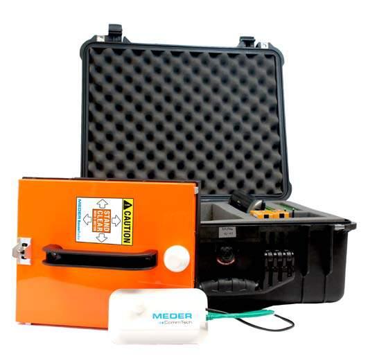
6 6 Delivery/ device parts 2. Scope of delivery / device parts The whole system is delivered in a Pelicase, which usually serves as workplace. The equipment consists of following components: 1 Casing (Pelicase) 1 1 Radar unit 2 The radar unit includes the entire RF-electronics from the antenna to the demodulator circuit, also the wireless-transmitter unit. The operating range is up to 30 m. 1 Wireless-receiver with connector cable to the PC 3 1 Charging device including additional manual 4 10 pieces 1,5 V batteries (size AA / LR6) 1 Operating and interpretation software 1 User Manual The dimensions of the antenna are 250 mm x 300 mm. The power supply is made very flexibly for working under field conditions. It is possible to use rechargable or non-rechargable batteries. The necessary notebook / PC is not included in the standard version of Life RescueRadar. It may be optionally added Figure 1: RescueRadar BR 502w 3
 and enter the value x of the IP-address 19")


 Subnet mask: 255.255.255.0 3.")
 to the PC. 5.")
7 7 Starting 3. Starting 1. Copy the files BioRadar Analyser.exe and BioRadar Analyser.ini to a common folder. Open the file BioRadar Analyser.ini (e.g. with editor) and enter the value x of the IP-address x, stated on the wireless receiver, in IpAddr. The other default parameters should not be changed. 2. Open Network Connections, under Settings in the Windows Start menu, and select the LAN connection the wireless receiver is connected to. Open the properties of the LAN connection by right click and open the properties of Internet Protocol (TCP/IP). Choose the button Advanced and add a new IP-address in the tab IP addresses : IP adresse: nn (nn >10) Subnet mask: Before starting, be sure that the accumulator stack in the radar unit is fully charged and the radar unit is switched off. 4. Connect the wireless-receiver with the provided cables (Ethernet, USB) to the PC. 5. Switch on the radar unit. The little green LED built in the handle turns on. 6. The green LED turns on when the radar unit is connected with the wireless receiver.
8 8 Operating state 4. Operating state If the input voltage is lower than 10 V., there will be an error message in the status window, please change the accumulators or batteries. 4.1 Changing the accumulators 1. Switch off the radar unit. There is no need to switch off the PC. 2. Remove the accumulator stack and insert the second one. 3. Switch on the radar unit. 4.2 Charging the accumulators For charging the accumulators, a V AC; 60 / 50 Hz power supply is required. A complete charging process of a totally discharged accumulator takes about 14 hours time. The accumulator is totally charged when the green LED at the charging device turns on. Depending on the type of accumulator, it must be fully discharged before recharging. 4.3 Charging device note on safety For detailed information please refer to added operating instructions of the charging device. 4.4 Accumulators note on safety 1. Do not bridge the poles of the accumulators. 2. The not throw accumulators or batteries in your domestic waste bin. Please recycle! 100 m free field conditions!
9 9 The first measurement 5. The first measurement 5.1 Preparative Place the antenna directly onto/abve the area you want to investigate. The better the contact of the antenna to the surface the less is the chance to collect unwanted signals. Run the RescueRadar software. On the desktop you see figure 2. To check normal function of the equipment it runs continuously a Self Check function. The arrows of the analogue displays in the status window (Input voltage, Internal voltage, Radar unit and Compensation) have to be in the green area. This process starts after getting a new antenna position and needs some seconds. 5.1 Start Data acquisition starts by mouse click on the button with the magnifying glass or by shortcut (shortcuts see page 12). The measured signal is displayed from right to left inside the window signal view. After a short time the evaluations are displayed inside the windows Fourier analysis view and wavelet analysis view. The analogue display of Compensation inside the window status window must be in the green area. It shows the operator the adaptation status of the antenna. The radar unit automatically adapts to the surface in front of it. This process starts after setting a new antenna position and needs some seconds. During this time the displayed signal of compensation is outside the green area and the measured data is useless. A strong movement in front of the antenna can cause a readaption of the system. If the display of Compensation after seconds is still outside the green area, displace the antenna about few centimetres. The data acquisition runs continuously, also the Fourier and wavelet analysis (see figure 3). 5.3 Finish Click on the button with the magnifying glas. The last 56 seconds of data will be displayed and can be recorded with a comment.


10 10 Interface Figure 2: Windows user interface Figure 3: display of the measuring data
11 11 Software description 6. Software description The measured data are displayed under the 32-bit software written for Windows. It requires at least a 133 MHz Pentium CPU. The processor performance has no influence on the quality of the measuring values. The measured data and mathematical results are displayed constantly and simultaneous in four windows (see figure 3): signal view Fourier analysis view wavelet analysis view status window Menu buttons: Open Description editor Save Setup window Acquisition emulation Start/Stop simulation About Signal acquisition Start/Stop measuring Exit BioRadar Analyser Print results All commands are possible to run by mouse or key operations.
12 12 Shortcuts 6.1 Shortcuts Mouse click Shortcut Description of operation File Open [Ctrl] + [O] open an already saved data file Save [Ctrl] + [S] save the recent file together, with added comments Print [Ctrl] + [P] print the open file, results and comments Export [Ctrl] + [R] save the recent file in ASCII format Exit [Ctrl] + [F4] quit the RescueRadar software [Ctrl] + [X] View Description [Ctrl] + [D] opens a text window where you can add your comments Data Acquisition [Ctrl] + [A] start or stop the data acquisition mode Emulation [Ctrl] + [E] start or stop the demonstration mode Options Setup setting of parameters
13 13 Analysis-options 6.2 Analysis-options: signal view Data acquisition starts by mouse click on the button with the magnifying glas or by shortcut - [Ctrl]+[A] The incoming data are displayed continuously from right to left (oscilloscopelike) inside the window signal view. The scale of this window is set automatically depending on incoming amplitude during the acquisition. The red and green lines show movements detected by the antenna. If both lines are flat, there is either no movement or no penetration is possible. For deeper understanding of the influencing variables training and experience is essential. For finishing the acquisition, click on the button with the magnifying glas or use the shortcut - [Ctrl]+[A]. The data of the last measuring period is displayed and ready for further operations. It is possible to cut (set to zero) unwanted parts of signal by marking them with the left mouse button. You update the wavelet analysis with a double click of the left mouse button within the window wavelet analysis. Fourier analysis view Accumulates the sums of the amplitudes of the single frequencies over the time period as displayed by the wavelet. The result is updated constantly. A high peak indicates a dominant frequency over a long time period.
14 14 Analysis-options wavelet analysis view Is a kind of graphic display showing the frequency spectrum of the current analogue signal in online mode. The diagram is displayed in three dimensions as a function of the time and displayed in the window wavelet analysis view. First dimension: Time axis (horizontally) Second dimension Frequency (vertically) Third dimension Amplitude of the frequency spectrum at the same time to the time axis in the window signal view high frequencies in the top of the window, low frequencies in the bottom of the window is shown by different colour and brightness values; dark for low amplitude, bright for high amplitude status window The status window is a set of gauges displaying the current electrical conditions of accumulator (Input voltage), proper function of internal electronics (Internal voltage), power consumption of the radar unit (Radar unit) and the compensation signal value of new local conditions (Compensation). After detection of a constant frequency during the time defined in the settings the Life indicator lights up. The amplitude is irrelevant.
15 15 Example1 7. Measurement examples and their interpretation Example 1 Example 1 displays a possible RescueRadar signal, the pertinent spectrums of the Fourier analysis and the wavelet analysis. It shows a clear breathing of a person. Typical breathing frequencies are in the range between 0,15 and 0,8 Hz. The Fourier analysis shows a dominant frequency of 0,26 Hz. This equals a breathing rate of approx. 15 times per minute. The wavelet analysis shows, that the dominant frequency was present over the entire measuring period. Result: The scale of 2 V, shown in the signal view, indicates a strong echo. The Life indicator is activated. The received echo matches biological patterns, life is very likely.
16 16 Example 2 Example 2 shows irregular signals. In spite of the chaotic signals Fourier is able to detect the dominant frequency of 0,3 to 0,4 Hz. The wavelet analysis shows scattered frequency occurrences but no constant dominant frequency over the time period. The Life indicator does not react. Result: Movement is detected. But the probability of a human breathing is rather low. Other action: Change the position or direction of the antenna in small steps and repeat the data acquisition: to get a better signal to ensure the probability of human life
17 17 Example 3 Example 3 The received signal is rhythmical with small amplitude (scale 0,25 V) over the entire measured period. The Fourier analysis shows a dominant frequency at 0,4 Hz. Also the wavelet analysis shows the dominant frequency over the entire period. The Life indicator is activated. Result: Biological patches where found under difficult conditions. The signals where very low (scale 0,25 V) but there where no additional noices detected.
18 18 Technical Data 8. Technical Data 8.1 Radar unit Transmitting unit Operation frequency: RF output: Modulation: 1299 MHz < 2 mw no modulation (continuous wave radar) Receiving unit Sensitivity: -90 dbm (S/N = 10 db) Antenna: permanently integrated in the radar unit Dimensions: 250 mm x 300 mm x 60 mm Operating position: optional Direction of radiation: vertical to the surface 250 x 300 Spread angle: approx Power supply Operating voltage: Power consumption: accumulator stack 12 V, 10x NiMh (size AA/LR6); > 2 Ah; 2 accumulator stacks (removable) Charging device for V approx. 4 W (without Notebook / PC) 8.3 Coupling to the notebook / PC Wireless receiver: LAN (TCP/IP) and USB (power supply) with IP-address: nn (nn > 10) Software: BioRadar Analyser for Windows 2000 / XP/ Vista / 7; software to record and evaluate the measured values on the monitor, storage on hard disk or mobile volume and printing Notebook / PC: Office-standards, no special requirements Outdoor design is recommended 8.4 Dimensions and weight Casing: Dimensions: Weight: Pelicase Width: 530 mm; Height: 420 mm; Depth: 220 mm approx. 12 kg
19 19 FAQs 9. FAQs Q: Can the RescueRadar be operated by a single person? A: Yes, it is easy to transport and operate. A second person might increase the effectiveness. Q: Is the emitted radiation dangerous? A: No, the emitted radiation is less 2mW. In fact it is about 1% of the emittation of a cell phone. Q: Can the RescueRadar find out how many persons are buried? A: No, multiple persons might cause a lot of signals in various frequency ranges. But the exact number can not be read out. Q: Does the RescueRadar provide distance to object? A: No, the RescueRadar is not using pulsed and swooping signals. Q: What is the opening angle of the radar beam? A: The opening angle is 55. With this angle the center of the beam provides about 50% sensitivity in the center of the beam. Q: Is a PC or Laptop required? A: Yes, the signal processing and the display of the measurements are shown on the screen. Q: Is it necessary to understand all diagrams on the screen? A: The displays help to get a deeper understanding of the location of a person. But the software does also show by a simple life indicator if biological signals are found. Q: Is the PC/ Laptop part of the bundle? A: We offer different bundles without Laptop and also including Laptop. Q: What is the working Principe of the RescueRadar? A: The RescueRadar is working with micro wave radar and uses Doppler effect for detection Q: What kind of signals is the RescueRadar detecting? A: The RescueRadar detects only movements not static echo s. This can be returning movements like breathing or heartbeat as well as one time actions like a moving person. Q: What does effect the signal strength? A: The signals are depending on the distance from object to antenna, the isolating properties of the material and the size of the moving surface. Q: What detection range has the BR? A: Mainly depending on the material to penetrate from 30m in air, to about 1m in armed concrete down to zero for wet materials like mud. Q: What is the used frequency range? A: The frequency is 1299 MHz with bandwidth of nearly zero.


 7731")
20 MEDER CommTech GmbH Robert-Bosch-Straße Singen / Htwl. Deutschland This dcoument can be downloaded at: Telefon: +49 (0) Telefax: +49 (0) info@meder-commtech.com
PIPELINE DEFECT MAPPER
 PIPELINE DEFECT MAPPER Receiver Colour Display C.A.T. Survey Graph ACVG Survey Graph GIS View General: The Pipeline Defect Mapper Kit designed and developed in such a way; to precisely locate and assist
AirScope Spectrum Analyzer User s Manual
 AirScope Spectrum Analyzer Manual Revision 1.0 October 2017 ESTeem Industrial Wireless Solutions Author: Date: Name: Eric P. Marske Title: Product Manager Approved by: Date: Name: Michael Eller Title:
PREMIUM MULTI PURPOSE BROAD BAND BUG DETECTOR (DRFD5)
") PREMIUM MULTI PURPOSE BROAD BAND BUG DETECTOR (DRFD5) RFD-5 is a highly sensitive wide-band radio frequency detector with large dynamic range and enormous frequency range. RFD-5 functionality is optimized
PREMIUM MULTI PURPOSE BROAD BAND BUG DETECTOR (DRFD5) RFD-5 is a highly sensitive wide-band radio frequency detector with large dynamic range and enormous frequency range. RFD-5 functionality is optimized
GPR SYSTEM USER GUIDE AND TROUBLESHOOTING GUIDE
 GPR SYSTEM USER GUIDE AND TROUBLESHOOTING GUIDE Implementation Report 5-4414-01-1 Project Number 5-4414-01 Subsurface Sensing Lab Electrical and Computer Engineering University of Houston 4800 Calhoun
4GHz / 6GHz Radiation Measurement System
 4GHz / 6GHz Radiation Measurement System The MegiQ Radiation Measurement System (RMS) is a compact test system that performs 3-axis radiation pattern measurement in non-anechoic spaces. With a frequency
Pulse Doppler Flow-Dop
 EDUCATION Pulse Doppler Flow-Dop GAMPT-50100 User Manual Fon: +49 (0) 3461-278 691-0 Fax: +49 (0) 3461-278 691-101 email: info@gampt.de Gesellschaft für Angewandte Medizinische Physik und Technik mbh (GAMPT
AW900-SPEC USER S MANUAL
 USER S MANUAL 900 MHz Site Survey Spectrum Analyzer Industrial-grade, long-range wireless Ethernet systems AvaLAN W I R E L E S S User s Manual Thank you for your purchase of the AW900-SPEC Site Survey
JUMO Wtrans E01. Measuring probe for humidity, temperature, and CO 2 with wireless data transmission. Brief description. Universal Wtrans receiver
 Page 1/13 JUMO Wtrans E01 Measuring probe for humidity, temperature, and CO 2 with wireless data transmission Humidity from 0 to 100 % RH (incl. -40 to +80 C) or CO 2 from 0 to 2000/5000/10000 ppm or Temperature
KMT - Kraus Messtechnik GmbH
 KMT - Kraus Messtechnik GmbH Gewerbering 9, D-83624 Otterfing, Germany, 08024-48737, Fax. 08024-5532 Home Page http://www.kmt-telemetry.com, Email: info@kmt-telemetry.com User Manual CTP8-Rotate 8 (4)
Operators Manual For Spectrum Analyser SA97
 Included with: Padded nylon carrying case. Mains battery charger. Car cigarette lighter charger lead. Quick reference card. RS232 interface socket. Operators Manual For Spectrum Analyser SA97 Features
Exercise 2-6. Target Bearing Estimation EXERCISE OBJECTIVE
 Exercise 2-6 EXERCISE OBJECTIVE When you have completed this exercise, you will be able to evaluate the position of the target relative to a selected beam using the A-scope display. You will be able to
Operating Instructions GEMINI R
 Operating Instructions GEMINI R 060999-104 02.09.2011 General Notes For your safety Documentation Please familiarise yourself with these operating instructions and the safety information it contains before
TWS One Vocal UHF wireless system. user manual
 TWS One Vocal UHF wireless system user manual Musikhaus Thomann Thomann GmbH Hans-Thomann-Straße 1 96138 Burgebrach Germany Telephone: +49 (0) 9546 9223-0 E-mail: info@thomann.de Internet: www.thomann.de
User Manual. User Manual. Wide Band Booster (30dBm) 2012 February. Information in this manual is subject to change without notice
 2012 February. Information in this manual is subject to change without notice") User Manual Wide Band Booster (30dBm) 2012 February Information in this manual is subject to change without notice 1 Table of Contents 1 Overview... 3 2 System Diagram... 4 3 Technical Specification...
User Manual Wide Band Booster (30dBm) 2012 February Information in this manual is subject to change without notice 1 Table of Contents 1 Overview... 3 2 System Diagram... 4 3 Technical Specification...
Dive deep into interference analysis
 Dive deep into interference analysis Dive deep into interference analysis Contents 1. Introducing Narda Outstanding features 2. Basics IDA 2 3. IDA 2 presentation How IDA 2 is used: 1) Detect 2) Analyze
INSTRUCTION MANUAL FOR ULTRASONIC/MICROWAVE SENSORS
 INSTRUCTION MANUAL FOR ULTRASONIC/MICROWAVE SENSORS 1)Install PROBE_GatewayPC Software on PC.Remove previous installation. In Windows Control Panel go to the Programs and Features, select Probe_GatewayPC_Net
KMT - Kraus Messtechnik GmbH
 KMT - Kraus Messtechnik GmbH Gewerbering 9, D-83624 Otterfing, Germany, 08024-48737, Fax. 08024-5532 Home Page http://www.kmt-telemetry.com, Email: info@kmt-telemetry.com CTP8-Rotate 8 (4) channel telemetry
TWS One Headset UHF wireless system. user manual
 TWS One Headset UHF wireless system user manual Musikhaus Thomann Thomann GmbH Hans-Thomann-Straße 1 96138 Burgebrach Germany Telephone: +49 (0) 9546 9223-0 E-mail: info@thomann.de Internet: www.thomann.de
Transient Data Acquisition System, TAS 4-40 Potential-free measurement of fast rise pulses:
 Transient Data Acquisition System, TAS 4-40 Potential-free measurement of fast rise pulses: High precision measurement of fast rising voltages and currents causes considerable problems in many spheres
INSTALLATION & MAINTENANCE
 ADVANTAGES High measurement precision of surface velocity due to advanced radar technology Fast installation above the surface, no complex construction works, or flow shutdown required 24/7 real-time monitoring
AW5800-SPEC USER S MANUAL
 USER S MANUAL 5.8 GHz Site Survey Spectrum Analyzer Industrial-grade, long-range wireless Ethernet systems AvaLAN W I R E L E S S User s Manual Thank you for your purchase of the AW5800-SPEC Site Survey
INTRODUCTION. Strong Performance: High resolution and penetration, achieving precise flaw detection
 Shantou Institute of Ultrasonic Instruments Co., Ltd. Add: 77 Jinsha Road, Shantou, Guangdong 515041, China Tel: 86-754-88250150 Fax: 86-754-88251499 Http://www.siui.com/ndt Product Data CTS-9009 Digital
Weather Radar Systems. General Description
 General Description Our weather radars are designed for precipitation monitoring at both regional and urban scales. They can be advantageously used as gap filler of existing radar networks particularly
Telemetrie-Messtechnik Schnorrenberg
 Telemetrie-Messtechnik Schnorrenberg CTP8-Rotate 8 (4) channel telemetry for rotating applications like wheels or rotors, high signal bandwidth, 16bit, software programmable Inputs for STG, TH-K, ICP or
2801 Multilock. Communications System Analyzer. Data Sheet. Boosting wireless efficiency
 Data Sheet 2801 Multilock Communications System Analyzer Boosting wireless efficiency A real multi-talented instrument the Willtek 2801 Multilock The Willtek 2801 Multilock is a test instrument for multiple
AIMS Radar Specifications
 Transmitted Frequency: Peak Radiated Power: Average Power: Antenna Beamwidth: 9.23 GHz 1 Watt (Optional 2 to 80 Watts) 6.25 microwatts up to 0.4 watts; < 1 milliwatt for most applications Fast-Scan (rotating):
MAGNETIC FIELD METER Operator s Manual
 Edition 3.1 2009-09-03 MAGNETIC FIELD METER 2000 Operator s Manual The MFM 2000 is a professional magnetic field instrument To make the best use of the instrument we recommend that you read this manual
Wireless sensor system
 Wireless sensor system Internet / Ounet PC in internal network GW Internet connection FIGURE 1 structure of wireless sensor network = Base station = Routing wireless sensor = Wireless sensor General description
DMS 700 Digital Microphone System
 40 pre-programmed frequencies Up to 100 channels can be operated simultaneously 8 hours battery life and 7-segment battery status information Quick setup mode, spectrum analyzer and rehearsal functions
CTP16-Rotate. KMT - Kraus Messtechnik GmbH
 KMT - Kraus Messtechnik GmbH Gewerbering 9, D-83624 Otterfing, Germany, 08024-48737, Fax. 08024-5532 Home Page http://www.kmt-telemetry.com, Email: info@kmt-telemetry.com CTP16-Rotate 16 channel telemetry
EITN90 Radar and Remote Sensing Lab 2
 EITN90 Radar and Remote Sensing Lab 2 February 8, 2018 1 Learning outcomes This lab demonstrates the basic operation of a frequency modulated continuous wave (FMCW) radar, capable of range and velocity
Antenna Overview. Version /10/20
 Antenna Overview Version 2.8 2010/10/20 Contents ANT-Ceiling-Mimo-2G for 802.11n AP Order No.: 5510000209...3 ANT-Omni-4-dual Order No.: 600529...4 ANT-RSMA.KS-D-060-03-1m Order No.: 600402...5 ANT-Omni-vehicle-1.2m
WEB I/O. Wireless On/Off Control USER MANUAL
 Wireless On/Off Control Technical Support: Email: support@encomwireless.com Toll Free: 1 800 617 3487 Worldwide: (403) 230 1122 Fax: (403) 276 9575 Web: www.encomwireless.com Warnings and Precautions Warnings
KNX radio wall-transmitter 1gang/2gang flat quicklink Order no.: 8565 x2 xx
 KNX radio wall-transmitter 1gang/2gang flat quicklink KNX radio wall-transmitter 1gang/2gang flat quicklink Order no.: 8565 x2 xx KNX radio wall-transmitter 1gang/2gang flat solar quicklink Order no.:
Quick Start Guide for the PULSE PROFILING APPLICATION
 Quick Start Guide for the PULSE PROFILING APPLICATION MODEL LB480A Revision: Preliminary 02/05/09 1 1. Introduction This document provides information to install and quickly start using your PowerSensor+.
IT-24 RigExpert. 2.4 GHz ISM Band Universal Tester. User s manual
 IT-24 RigExpert 2.4 GHz ISM Band Universal Tester User s manual Table of contents 1. Description 2. Specifications 3. Using the tester 3.1. Before you start 3.2. Turning the tester on and off 3.3. Main
SDR 4++ Dual Diversity SDR Receiver. Operating Guide. version 1.0
 Cross Country Wireless, 7 Thirlmere Grove, BOLTON, BL4 0QB, UK Email chrism@crosscountrywireless.net Web page http://www.crosscountrywireless.net Telephone +44 (0) 1204 410626 Mobile / Workshop +44 (0)
Connecting the Radio:
 Connecting the Radio: Step 1: Connect the Cat5 cable from the radio into the RJ-45 jack marked CPE on the POE injector. The POE injector is not weather proof and should be installed indoors. Step 2: Connect
L O C A T O R G P R. Introducing the. Radarteam. Ground Probing Radar/Antenna system with Rugged PC and Cart ü
 Introducing the L O C A T O R G P R Ground Probing Radar/Antenna system with Rugged PC and Cart ü Fully integrated system. Multi Frequency operation: 100-900 MHz ü Air/Ground Coupled operation. Multiple
Continuously monitors and stores the levels of Electromagnetic fields Up to four simultaneous bands: GSM 900 / 1800 MHz / UMTS / Broadband 100 khz 3
 Continuously monitors and stores the levels of Electromagnetic fields Up to four simultaneous bands: GSM 900 / 1800 MHz / UMTS / Broadband 100 khz 3 GHz Magnetic fields monitoring from 10 Hz to 5 khz Automatic
Wireless wall transmitter, 1-gang with inscription space, Wireless wall transmitter, 3-gang with inscription space
 Wireless wall transmitter, 1-gang with inscription space Order No. : 5331.. Wireless wall Order No. : 5333.. Operating instructions 1 Safety instructions Electrical devices may only be mounted and connected
RF Wireless Serial Device Server
 RF-SDS RF Wireless Serial Device Server The RF-SDS subassembly is a radio transceiver acting as a Serial Device Server, which externally connects a remote serial RF transceiver to an Ethernet network (TCP/IP).
10/17/2011. I have an Air-Card. I have Satellite Internet. Why would I use Wi-Fi? Just for
 How much do you use the Internet? Just for e-mail Or. 2011 National HDT Rally How much do you use the Internet? How much do you use the Internet? E-mail Face Book Google Plus Blog reading Blog Writing
Exercise 4-1. Chaff Clouds EXERCISE OBJECTIVE
 Exercise 4-1 Chaff Clouds EXERCISE OBJECTIVE To demonstrate chaff as a method of denying target information to a radar. To verify whether MTI processing is an effective anti-chaff processing technique
Contents Technical background II. RUMBA technical specifications III. Hardware connection IV. Set-up of the instrument Laboratory set-up
 RUMBA User Manual Contents I. Technical background... 3 II. RUMBA technical specifications... 3 III. Hardware connection... 3 IV. Set-up of the instrument... 4 1. Laboratory set-up... 4 2. In-vivo set-up...
Sentinel 3: Speed, flexibility, certainty
 ]= V1.2 Sentinel 3: Speed, flexibility, certainty Sentinel 3 is the most advanced RF over fiber test and measurement system for: EMP test and EMC conformance HIRF aircraft clearance Simulated lightning
STC65 RS485 Modbus. EnOcean Receiver/Transmitter with RS485 Modbus Interface. Data Sheet. Application. Security Advice Caution.
 STC65 RS485 Modbus EnOcean Receiver/Transmitter with RS485 Modbus Interface Data Sheet Subject to technical alteration Issue date: 27.06.2014 Application Bidirectional gateway for EnOcean-based sensors
free solo HT 1.8 GHz UHF wireless system user manual
 free solo HT 1.8 GHz UHF wireless system user manual Musikhaus Thomann Thomann GmbH Hans-Thomann-Straße 1 96138 Burgebrach Deutschland Telephone: +49 (0) 9546 9223-0 E-mail: info@thomann.de Internet: www.thomann.de
Instruction Manual. Ultrasonic and Radar
 Instruction Manual ABM Gateway Software for 3 & 4 wire Ultrasonic and Radar Instruction Manual Revision 5.8 NOTE: Windows 7 and 8 users are asked to use default screen size (100%). To change from Larger
PORTABLE SPECTRUM ANALYZER WITH BUILT-IN SIGNAL GENERATOR. Arinst SSA-TG R2
 SCIENTIFIC AND PRODUCTION COMPANY PORTABLE SPECTRUM ANALYZER WITH BUILT-IN SIGNAL GENERATOR Arinst SSA-TG R2 USER MANUAL Article 1484 CONTENT 1. PURPOSE...... 3 2. SPECIFICATIONS... 3 3. COMPLETENESS.....
Spectrum & Power Measurements Using the E6474A Wireless Network Optimization Platform Application Note By Richard Komar
 Spectrum & Power Measurements Using the E6474A Wireless Network Optimization Platform Application Note By Richard Komar Contents Introduction...1 Band Clearing...2 Using the spectrum analyzer for band
Quick Start Instructions EMV-INspektor V2
 Connecting the : The illustration below shows the connection diagram for the. Step 1: Before connecting the to the voltage supply, first establish the connection of the to the measuring clamp adapters.
SGD-EEM «MEDUSA» GEOELECTRICAL MULTIFUNCTION RECEIVER
 Research and Production Company Sib Geofiz Pribor SGD-EEM «MEDUSA» GEOELECTRICAL MULTIFUNCTION RECEIVER Version V2.2 OPERATIONS MANUAL 2012 2 Operation Manual Sib Geofiz Pribor SGD-EEM «MEDUSA» 3 CONTENTS
Review: The MFJ-225 Graphical Antenna Analyzer Phil Salas AD5X
 Review: The Graphical Antenna Analyzer Phil Salas AD5X The has a back-lit 3 LCD graphic display that simultaneously shows the frequency or swept frequency range, unsigned complex impedance, impedance magnitude,
NDT Supply.com 7952 Nieman Road Lenexa, KS USA
 Smartor Ultrasonic Flaw Detector & Thickness Gauge One-hand Operation Smart Test Wizard Weld Simulation Advanced Conventional UT & Thickness Measurement SIUI s new Smartor is a combination ultrasonic testing
MINIMUM SYSTEM REQUIREMENTS
 Quick Start Guide Copyright 2000-2012 Frontline Test Equipment, Inc. All rights reserved. You may not reproduce, transmit, or store on magnetic media any part of this publication in any way without prior
WE-525T Antenna Analyzer Manual and Specification
 WE-525T Antenna Analyzer Manual and Specification 1.0 Description This product is designed to speed and ease the testing and tuning of antenna systems. Graphical displays of SWR, Return loss, Distance
WPE 48N USER MANUAL Version1.1
 Version1.1 Security instructions 1. Read this manual carefully. 2. Follow all instructions and warnings. 3. Only use accessories specified by WORK PRO. 4. Follow the safety instructions of your country.
Spectrum Analyzer R&S FS300
 Spectrum Analyzer R&S FS300 9 khz to 3 GHz The new product family from Rohde & Schwarz Professional test equipment for laboratory, service and production The R&S FS300 is a highly accurate spectrum analyzer
For use with the emwave Desktop PC version Dual Drive for emwave User Guide User Guide
 Dual For Drive use for emwave with User the Guide emwave Desktop PC version User Guide i Welcome to the World of Dual Drive Pro Dual Drive runs in conjunction with the emwave Desktop (PC version) and is
Fixed head Doppler radars
 Weibel Scientific Solvang 30 3450 Allerød Denmark Fixed head Doppler radars Network ready for the future 1. Introduction The network ready SL-xxxP family of fixed head Weibel Doppler Radar Systems are
Frequency-Modulated Continuous-Wave Radar (FM-CW Radar)
") Frequency-Modulated Continuous-Wave Radar (FM-CW Radar) FM-CW radar (Frequency-Modulated Continuous Wave radar = FMCW radar) is a special type of radar sensor which radiates continuous transmission power
Frequency-Modulated Continuous-Wave Radar (FM-CW Radar) FM-CW radar (Frequency-Modulated Continuous Wave radar = FMCW radar) is a special type of radar sensor which radiates continuous transmission power
External Source Control
 External Source Control X-Series Signal Analyzers Option ESC DEMO GUIDE Introduction External source control for X-Series signal analyzers (Option ESC) allows the Keysight PXA, MXA, EXA, and CXA to control
Black Marlin radar systems may be purchased with a flat-top radome for mounting cameras on
 SPECIFICATIONS The Black Marlin is DMT s midrange security radar system. It may be used to search and track threats from land and sea. This radar is an X- Band, pulsed- Doppler system that operates in
Connecting two Phoenix Studio Audiocodecs through a point-to-point IP radio link operating in the 5 GHz band
 APPLICATION NOTE Connecting two Phoenix Studio Audiocodecs through a point-to-point IP radio link operating in the 5 GHz band AEQ PHOENIX AUDIOCODECS. APPLICATION NOTE 4 Connecting two Phoenix Studio Audiocodecs
P a g e 1 ST985. TDR Cable Analyzer Instruction Manual. Analog Arts Inc.
 P a g e 1 ST985 TDR Cable Analyzer Instruction Manual Analog Arts Inc. www.analogarts.com P a g e 2 Contents Software Installation... 4 Specifications... 4 Handling Precautions... 4 Operation Instruction...
3 GHz Carrier Backhaul Radio. Model: AF-3X. Tel: +44 (0) Fax: +44 (0) LINK GPS MGMT DATA DATA
 Fax: +44 (0) LINK GPS MGMT DATA DATA") LINK GPS MGMT DATA DATA MGMT GPS LINK 3 GHz Carrier Backhaul Radio Model: AF-3X LINK GPS MGMT DATA 3 GHz Carrier Backhaul Radio Model: AF-3X LINK GPS MGMT DATA DATA MGMT GPS LINK Introduction Thank you
LINK GPS MGMT DATA DATA MGMT GPS LINK 3 GHz Carrier Backhaul Radio Model: AF-3X LINK GPS MGMT DATA 3 GHz Carrier Backhaul Radio Model: AF-3X LINK GPS MGMT DATA DATA MGMT GPS LINK Introduction Thank you
Exercise 4. Angle Tracking Techniques EXERCISE OBJECTIVE
 Exercise 4 Angle Tracking Techniques EXERCISE OBJECTIVE When you have completed this exercise, you will be familiar with the principles of the following angle tracking techniques: lobe switching, conical
Life Detection System: Based on L&S band microwaves 1.INTRODUCTION Department of Electronics and Communication College of Engineering, Adoor
 1.INTRODUCTION A new sensitive microwave life-detection system which can be used to locate human subjects buried under earthquake rubble or hidden behind various barriers has been constructed. By advent
Frequency Agility and Barrage Noise Jamming
 Exercise 1-3 Frequency Agility and Barrage Noise Jamming EXERCISE OBJECTIVE To demonstrate frequency agility, a radar electronic protection is used against spot noise jamming. To justify the use of barrage
SDI. Table of Contents
 NMSC-2 User Manual 2 Table of Contents Introduction........ 4 Hardware Installation.... 5 NMSC Power On.. 8 Overview... 9 FFT Measurement Screen.. 10 FFT Setup..... 11 FFT Detector..... 14 FFT Calibration.....
Faculty of Electrical & Electronics Engineering BEE4233 Antenna and Propagation. LAB 1: Introduction to Antenna Measurement
 Faculty of Electrical & Electronics Engineering BEE4233 Antenna and Propagation LAB 1: Introduction to Antenna Measurement Mapping CO, PO, Domain, KI : CO2,PO3,P5,CTPS5 CO1: Characterize the fundamentals
User Manual. ilive 2 Wireless microphone system
 User Manual ilive 2 Wireless microphone system Safety instructions When using this electronic device, basic precautions should always be taken, including the following: 1 Read all instructions before using
inphoto ID PS Automatic ID photography With Canon PowerShot camera User Guide
 inphoto ID PS Automatic ID photography With Canon PowerShot camera User Guide 2018 Akond company Phone/fax: +7(812)384-6430 Cell: +7(921)757-8319 e-mail: info@akond.net akondsales@gmail.com http://www.akond.net
inphoto ID Canon camera control software Automatic ID photography User Guide
 inphoto ID Canon camera control software Automatic ID photography User Guide 2008 Akond company 197342, Russia, St.-Petersburg, Serdobolskaya, 65A Phone/fax: +7(812)600-6918 Cell: +7(921)757-8319 e-mail:
Deceptive Jamming Using Amplitude-Modulated Signals
 Exercise 3-1 Deceptive Jamming Using Amplitude-Modulated Signals EXERCISE OBJECTIVE To demonstrate the effect of AM noise and repeater inverse gain jamming, two angular deceptive EA used against sequential
General purpose Signal generation and analysis. Well-equipped for field and lab the R&S Spectrum Rider
 General purpose Signal generation and analysis Well-equipped for field and lab the R&S Spectrum Rider 32 The new R&S Spectrum Rider makes spectrum analysis in the field and lab easier, faster and more
Amplifier Test Bench Taking performance to a new peak
 Data Sheet Amplifier Test Bench Taking performance to a new peak Amplifier Test Bench Boonton s Amplifier Test Bench is a powerful software tool especially designed for efficient and accurate, test verification
Measuring and monitoring with precision. NRA-RX Narda Remote Analyzer
 Measuring and monitoring with precision NRA-RX Narda Remote Analyzer Exceptional: Measurement range. Exemplary: Price and performance The Narda NRA Series is a winner, thanks to its exceptional range of
User Manual CTP4/8/16
 KMT - Kraus Messtechnik GmbH Gewerbering 9, D-83624 Otterfing, Germany, 08024-48737, Fax. 08024-5532 Home Page http://www.kmt-telemetry.com, Email: info@kmt-telemetry.com User Manual CTP4/8/16 4/8/16-channel
ST600 TRANSMITTER OPERATING INSTRUCTIONS
 ST600 TRANSMITTER OPERATING INSTRUCTIONS 1892 1273 These operating instructions are intended to provide the user with sufficient information to install and operate the unit correctly. The Wood and Douglas
Technical Documentation
 Technical Documentation for metratec QuasarMX HF RFID Reader Date: April 2015 Version: 1.4 Technical Documentation metratec QuasarMX Page 1 of 13 Table of Contents 1 General Information / Security Advice...3
ELDES / METEK Weather Radar Systems. General Description
 General Description Our weather radars are designed for precipitation monitoring at both regional and urban scales. They can be advantageously used as gap fillers of existing radar networks particularly
Contents. Telecom Service Chae Y. Lee. Data Signal Transmission Transmission Impairments Channel Capacity
 Data Transmission Contents Data Signal Transmission Transmission Impairments Channel Capacity 2 Data/Signal/Transmission Data: entities that convey meaning or information Signal: electric or electromagnetic
Connecting two Phoenix Studio Audiocodecs through a point-to-point IP radio link operating in the 5 GHz band
 APPLICATION NOTE Connecting two Phoenix Studio Audiocodecs through a point-to-point IP radio link operating in the 5 GHz band AEQ PHOENIX AUDIOCODECS. APPLICATION NOTE 4-B Connecting two Phoenix Studio
Antennas and Propagation
 Antennas and Propagation Chapter 5 Introduction An antenna is an electrical conductor or system of conductors Transmission - radiates electromagnetic energy into space Reception - collects electromagnetic
USB-UT350(T) Portable Ultrasonic Pulser/Receiver and Analog to Digital Converter. User s Guide
 Portable Ultrasonic Pulser/Receiver and Analog to Digital Converter. User s Guide") USB-UT350(T) Portable Ultrasonic Pulser/Receiver and Analog to Digital Converter User s Guide 2000-2009 US Ultratek, Inc. Revision 1.77 September 30, 2009 US Ultratek, Inc. 4070 Nelson Ave., Suite B Concord,
USB-UT350(T) Portable Ultrasonic Pulser/Receiver and Analog to Digital Converter User s Guide 2000-2009 US Ultratek, Inc. Revision 1.77 September 30, 2009 US Ultratek, Inc. 4070 Nelson Ave., Suite B Concord,
User Guide for the Calculators Version 0.9
 User Guide for the Calculators Version 0.9 Last Update: Nov 2 nd 2008 By: Shahin Farahani Copyright 2008, Shahin Farahani. All rights reserved. You may download a copy of this calculator for your personal
Impedance Transformation with Transmission Lines
 Impedance Transformation with Transmission Lines Software Installation and Operation Manual Don Cochran WAØJOW 21826 Gardner Rd. Spring Hill, KS 66083 (913) 856-4075 Manual Revision 1 Page 1 Table of Contents
Mean currents and turbulence, plus wave height, direction and ice tracking
 Mean currents and turbulence, plus wave height, direction and ice tracking The ADCP is designed for flexibility. It measures current profiles at up to 8 Hz sampling frequency. It can also measure direct
Spectrum Analyzer TEN MINUTE TUTORIAL
 Spectrum Analyzer TEN MINUTE TUTORIAL November 4, 2011 Summary The Spectrum Analyzer option allows users who are familiar with RF spectrum analyzers to start using the FFT with little or no concern about
Exercise 1-5. Antennas in EW: Sidelobe Jamming and Space Discrimination EXERCISE OBJECTIVE
 Exercise 1-5 Antennas in EW: Sidelobe Jamming EXERCISE OBJECTIVE To demonstrate that noise jamming can be injected into a radar receiver via the sidelobes of the radar antenna. To outline the effects of
Selective and broadband high frequency field analysis
 ELECTRIC AND MAGNETIC FIELD ANALYZER EHP-200A Selective and broadband high frequency field analysis New solution for isotropic measurements in the 9 khz 30 MHz range Electric Fields from 0.02 to 1000 V/m
ZONESCAN net Version 1.4.0
 ZONESCAN net.0 REV 1. JW ZONESCAN net 2 / 56 Table of Contents 1 Introduction... 5 1.1 Purpose and field of use of the software... 5 1.2 Software functionality... 5 1.3 Function description... 6 1.3.1
MICROWAVE FREQUENCY SYNTHESIZER QP-FSPLL USER MANUAL
 MICROWAVE FREQUENCY SYNTHESIZER QP-FSPLL-0040-01 USER MANUAL The QP-FSPLL-0040-01 is a low-phase noise wideband synthesizer operating from 50 MHz to 40 GHz with a nominal output power of +15 dbm. The synthesizer
WMS 450 Wireless Microphone System
 Half 19 all metal case diversity receiver Automatic frequency setup function for quick and easy operation 12 pre-programmed frequencies per group Infrared link of all frequency and setup data to the transmitter
IEM 200 R UHF receiver. user manual
 IEM 200 R UHF receiver user manual Musikhaus Thomann Thomann GmbH Hans-Thomann-Straße 1 96138 Burgebrach Germany Telephone: +49 (0) 9546 9223-0 E-mail: info@thomann.de Internet: www.thomann.de 17.11.2015,
WE-2705P Antenna Analyzer
 1.0 Features: WE-2705P Antenna Analyzer Frequency range 1.5 2700 MHz Graphical display of SWR, Return loss, and Distance to Fault Smith chart display of Impedance Numerical display of Z=R+jX, L, C, Z,
RigExpert AA-170 Antenna Analyzer (0.1 to 170 MHz) User s manual
 User s manual") RigExpert AA-170 Antenna Analyzer (0.1 to 170 MHz) User s manual Table of contents 1. Description... 3 2. Specifications... 4 3. Precautions... 5 4. Operation... 6 4.1. Preparation for use... 6 4.2. Turning
RigExpert AA-170 Antenna Analyzer (0.1 to 170 MHz) User s manual Table of contents 1. Description... 3 2. Specifications... 4 3. Precautions... 5 4. Operation... 6 4.1. Preparation for use... 6 4.2. Turning
Qosmotec. Software Solutions GmbH. Technical Overview. QPER C2X - Car-to-X Signal Strength Emulator and HiL Test Bench. Page 1
 Qosmotec Software Solutions GmbH Technical Overview QPER C2X - Page 1 TABLE OF CONTENTS 0 DOCUMENT CONTROL...3 0.1 Imprint...3 0.2 Document Description...3 1 SYSTEM DESCRIPTION...4 1.1 General Concept...4