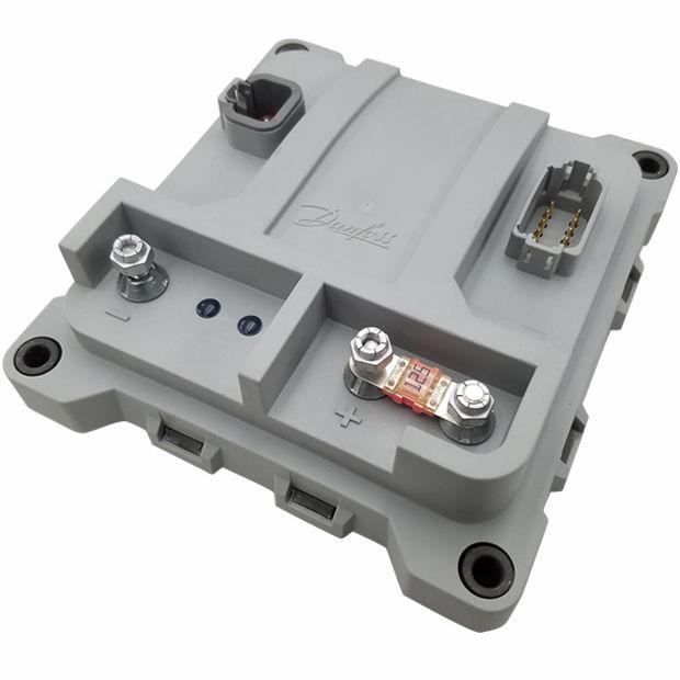
PLUS+1 High Current Controller Family
|
|
|
- Antony Sullivan
- 6 years ago
- Views:
Transcription

1 Technical Information PLUS+1 powersolutions.danfoss.com
2 Revision history Table of revisions Date Changed Rev June 2017 First edition Danfoss June 2017 BC en-US0101
3 Contents literature references Technical Information (TI)... 4 Module product Data Sheet (DS)...4 API specifications (API)... 4 PLUS+1 GUIDE User Manual... 4 User liability and safety statements OEM responsibility... 5 Overview... 6 Inputs/outputs types and specifications Input types... 7 DIN/AIN, A/D Refresh Rates... 7 DIN/AIN/FreqIN/Rheo...9 RheoIN Output types...13 PWMOUT/DOUT...13 LEDs Controller Area Network (CAN) CAN system design...15 Specifications for terminating resistor Notes on CAN Bus installation...15 Expansion module CAN Bus loading Product ratings Module supply voltage/maximum current ratings EEPROM write/erase ratings...17 High Current Controller general ratings...17 Environmental testing criteria...18 Modules housing...19 Product installation and start-up Connectors Mounting Machine diagnostic connector Grounding Hot plugging Machine wiring guidelines Machine welding guidelines...21 PLUS+1 USB/CAN Gateway...22 Danfoss June 2017 BC en-US0101 3
4 literature references Literature title Document type Literature ID PLUS+1 Technical Information User Guide BC PLUS+1 MC Data Sheet Data Sheet AI PLUS+1 GUIDE Software User Manual Operation Guide Comprehensive technical literature online at powersolutions.danfoss.com Technical Information (TI) A TI is comprehensive information for engineering and service personnel to reference. Module product Data Sheet (DS) A module product DS contains summarized information and parameters that are unique to an individual PLUS+1 module, including: Numbers and types of inputs and outputs Module connector pin assignments Module maximum current capacity Module sensor power supply (if present) current capacity Module installation drawing Module weights Product ordering information API specifications (API) Module API specifications contain detailed information about the module BIOS. PLUS+1 BIOS functionality is pin dependent. Pins are defined in module data sheets as C (connector number) p (pin number). API specifications include: Variable name Variable data type Variable direction (read/write) Variable function and scaling Module API specifications are the definitive source of information regarding PLUS+1 module pin characteristics. PLUS+1 GUIDE User Manual This user operation manual (OM) details information regarding the PLUS+1 GUIDE tool set that is used to build PLUS+1 applications. This OM covers the following broad topics: How to use the PLUS+1 GUIDE graphical application development tool to create machine applications How to configure module input and output parameters How to download PLUS+1 GUIDE applications to target PLUS+1 hardware modules How to upload and download tuning parameters How to use the PLUS+1 Service Tool 4 Danfoss June 2017 BC en-US0101
5 User liability and safety statements OEM responsibility The OEM of a machine or vehicle in which Danfoss products are installed has the full responsibility for all consequences that might occur. Danfoss has no responsibility for any consequences, direct or indirect, caused by failures or malfunctions. Danfoss has no responsibility for any accidents caused by incorrectly mounted or maintained equipment. Danfoss does not assume any responsibility for Danfoss products being incorrectly applied or the system being programmed in a manner that jeopardizes safety. All safety critical systems shall include an emergency stop to switch off the main supply voltage for the outputs of the electronic control system. All safety critical components shall be installed in such a way that the main supply voltage can be switched off at any time. The emergency stop must be easily accessible to the operator. Danfoss June 2017 BC en-US0101 5
6 Overview These modules communicate with one another and other intelligent systems over a machine Controller Area Network (CAN) data bus. PLUS+1 Mobile Machine Modules are designed to provide flexible, expandable, powerful and cost effective total machine management systems for a wide variety of vehicle applications. PLUS+1 controller products utilize modular designs wherever possible. This modularity extends to product housings, connectors and control circuitry. PLUS+1 hardware products are designed to be equally effective in a distributed CAN system, with intelligence in every node, or as stand-alone control for smaller machine systems. PLUS+1 Compliant systems are incrementally expandable: additional modules can be easily added to the machine CAN bus to increase system capabilities or computational power. The PLUS+1 High Current controller employs a 32 bit Cortex-M3 Processor, providing the controller with extremely fast single cycle processing speed and 512K internal flash. It features high current capabilities for your machine control. 6 Danfoss June 2017 BC en-US0101
7 Inputs/outputs types and specifications PLUS+1 modules have input or output pins that support multiple functions. Pins that support multiple input or output types are user-configurable using PLUS+1 GUIDE software. Refer to product data sheets for the input/output (I/O) content of individual modules. Input types Digital or Analog (DIN/AIN) Multifunctional Digital/Analog/Frequency/Rheostat (DIN/AIN/FreqIN/Rheo) Each PLUS+1 module input pin supports one of the above functional types. For pins with multiple functions, input configurations are user programmable using PLUS+1 GUIDE templates. DIN/AIN, A/D Refresh Rates Multifunction pins that are configured to be Digital input (DIN) are subject to the same update rates as the Analog input (AIN) function for that pin. Debounce is not used, as hysteresis is built into the function. The time to recognize a transition is dependent on the timing of the switch activation and the sample rate. General response to input time Description Response to input below minimum voltage Response to input above maximum voltage Response to input open Voltage working ranges Comment Non-damaging, non-latching; reading saturates to the low limit. Non-damaging, non-latching; reading saturates to the high limit. Pin configuration dependent: No pull up/ no pull down Pull up to 5 Vdc = 5 Vdc Pull down = 0 Vdc Pull up/ pull down = 2.5 Vdc Programmable (see specific data sheets for ranges). DIN/AIN characteristics Description Values Unit Comment General Min. Typ. Max. Input voltage range 0 36 V Maximum Voltage at pin. Low level digital input V Level adjustable in software. High level digital input V Level adjustable in software Voltage >= Vin high, Digital Input = True Time to change state in response to step input Middle range Minimum discernible voltage 0.02 V Maximum discernible voltage V Resolution 1.3 mv --- ms Depends on application (OS.ExecTime) Worst case offset and gain error ±0.12 V At V Measure = 5.26V Non-linearity ± 3.8 mv Input impedance kω Input impedance (5V/GND) kω Pull up or pull down (Vin < 5.7V) Input impedance (2.5V) kω Pull up and pull down (Vin < 5.7V) High range Minimum discernible voltage 0.13 V Danfoss June 2017 BC en-US0101 7
8 Inputs/outputs types and specifications DIN/AIN characteristics (continued) Description Values Unit Comment Min. Typ. Max. Maximum discernible voltage V Resolution 9 mv Worst case offset and gain error 1.1 V At V measure = 35.3V Non-linearity ±26 mv Input impedance kω No pull up or pull down (Vin < 5.7V) Input impedance (5V/GND) kω Pull up or pull down (Vin < 5.7V) Input impedance (2.5V) kω Pull up and pull down (Vin < 5.7V) Input impedance (Vin > 5.75V) High range input impedance for DA inputs 30 See High range input impedance for DA inputs, below. 25 kohms Rda np ( Vin) Rda pu ( Vin) Rda pd ( Vin) Rda pupd ( Vin) Vin Volts In high range the input impedance decreases as the input voltage increases. 8 Danfoss June 2017 BC en-US0101
9 Inputs/outputs types and specifications General response to input time DIN/AIN/FreqIN/Rheo The characteristics of Digital/Analog/Frequency/Rheostat (DIN/AIN/FreqIN/Rheo) pins are PLUS+1 GUIDE software controlled. The input can be digital, analog, frequency, or rheostat. Inputs can be pulled to 5 Vdc, pulled to ground, pulled to 2.5 Vdc, or no pull-up/pull-down. Description Response to input below minimum voltage Response to input above maximum voltage Expected measurement Pull up/pull down configuration Maximum frequency Comment Non-damaging, non-latching; reading saturates to the low limit. Non-damaging, non-latching; reading saturates to the high limit. Frequency (Hz) Period (0.1 µsec) Channel to channel phase shift (paired inputs... ) (0.1 ms). PWM duty cycle (0.01%) Duty cycle measurement only valid up to 5 khz (FreqIN). Edge count. Quadrature count (paired inputs driven from a quadrature encoder). No pull down/ pull up is standard with pull up or pull down programmable; failure modes are detectable. The controller may re-boot under some high frequency load conditions above 10 khz. DIN/AIN/FreqIN/Rheo characteristics Description Values Unit Comment Min. Typ. Max. Input voltage range 0 36 V Maximum voltage at pin Frequency range 0 10,000 Hz Quad count or Phase shift 0 5,000 Hz Low level digital input V Level adjustable in software High level digital input V Level adjustable in software Voltage >= Vin high, Digital Input = True Time to change state in response to step input Low range Minimum discernible voltage Maximum discernible voltage --- ms Depends on application (OS.ExecTime) 12.8 mv mv Resolution 0.09 mv Worst case offset and gain error Non-linearity ±0.3 mv Rising Voltage Threshold Falling Voltage Threshold ±24 mv At V measure = 368mV 0.29 V Voltage required for frequency input 0.04 V Voltage required for frequency input Input Impedance kω No pull up or pull down Danfoss June 2017 BC en-US0101 9
10 Inputs/outputs types and specifications DIN/AIN/FreqIN/Rheo characteristics (continued) Description Values Unit Comment Input Impedance (5V/ GND) Min. Typ. Max kω Pull up or pull down Input Impedance (2.5V) kω Pull up and pull down Middle range Minimum discernible voltage Maximum discernible voltage 0.02 V V Resolution 1.3 mv Worst case offset and gain error Non-linearity ± 3.8 mv Rising Voltage Threshold Falling Voltage Threshold ±0.07 V At V measure = 5.26V 3.89 V Voltage required for frequency input 0.85 V Voltage required for frequency input Input Impedance kω No pull up or pull down Input Impedance (5V/ GND) kω Pull up or pull down Input Impedance (2.5V) kω Pull up and pull down High range Minimum discernible voltage Maximum discernible voltage 0.13 V V Resolution 9 mv Worst case offset and gain error Non-linearity ±26 mv Rising Voltage Threshold Falling Voltage Threshold ±0.78 V At V measure = 35.3V 26.3 V Voltage required for frequency input 5.6 V Voltage required for frequency input Input Impedance kω No pull up or pull down (Vin < 5.7V) Input Impedance (5V/ GND) kω Pull up or pull down (Vin < 5.7V) Input Impedance (2.5V) kω Pull up and pull down (Vin < 5.7V) Input Impedance (Vin > 5.7V) See chart below 10 Danfoss June 2017 BC en-US0101
11 Inputs/outputs types and specifications High range input impedance for DAFR inputs kohms Rdafr np Rdafr pu Rdafr pd Rdafr pupd ( Vin) ( Vin) ( Vin) ( Vin) Vin Volts In high range the input impedance decreases as the input voltage increases. RheoIN Rheostat Input (RheoIN) characteristics Description Values Unit Comment Min. Typ. Max. Input impedance kω Minimum discernible resistance Maximum discernible resistance 6 Ω 10,000 Ω Measurement error 6 % 100Ω Measurement error 1.8 % 1kΩ Measurement error 4.7 % 10kΩ Danfoss June 2017 BC en-US
12 Inputs/outputs types and specifications Resistance versus maximum measurement error Error (%) Er (ji) i Resistance (kohm) 12 Danfoss June 2017 BC en-US0101
13 Inputs/outputs types and specifications Output types 15A Pulse Width Modulated (PWM/DOUT) 25A Pulse Width Modulated (PWM/DOUT) PWMOUT/DOUT All PLUS+1 module proportional outputs are Pulse Width Modulated (PWM). PWM frequency is software adjustable using PLUS+1 GUIDE. A low frequency dither may also be added with software to some outputs (see individual module API specifications for PWM outputs that support dither). There are two modes of PWM operation: open loop and closed loop (current control). In open loop mode, current can be sourced or sunk, but the output is a PWM duty cycle. Current feedback may be monitored in open loop mode, but the output is a constant voltage, not a constant current. The signal line of PVG valves can be driven with an open loop PWM. The PWM driving the control signal must be set to 0 at the same time as the digital output driving the PVE power pin is set to 0. If the maximum current is exceeded, the controller kernel will shut down the output and latch it. The kernel also limits how quickly the output can be repowered (250 ms). The output cannot be reset until the command goes to 0 or False (if configured as a digital output). There is built in thermal protection that will reduce the maximum current (closed loop) or the maximum duty cycle (open loop) if the internal temperature becomes too high. Refer to individual module data sheets for the maximum allowable output current for each PLUS+1 module. General Description Configuration Type (Linear vs. PWM) Operating modes Short circuit to ground and battery Mode selection (current or voltage) and full scale current ranges Comment Sourcing or sinking PWM Programmable: closed loop current or open loop voltage (duty cycle) Output fully protected against damage and fault detected Programmable PLUS+1 PWM output circuits are not designed to be used as inputs. Output current feedback readings should be used for fault checking only. C Caution Warranty will be voided if module is damaged. Avoid significant current driven back through an output pin. 15A PWM Description Values Unit Comment Min. Typ. Max. Output Vbattery V Iout = 15A Output current/ Duty cycle Measurable current range A % A % 33.3 A Resolution 2.1 ma Internal temperature < 85 C (185 F) Internal temperature > 105 C (221 F) Danfoss June 2017 BC en-US
14 Inputs/outputs types and specifications 15A PWM (continued) Description Values Unit Comment DC overcurrent trip point Min. Typ. Max A Latching PWM frequency and 20,000 Hz Running at higher PWM frequencies increases the internal losses. This may reduce the available output current due to thermal limiting. 25A PWM Description Values Unit Comment Min. Typ. Max. Output Vbattery V Iout = 25A Output current/ Duty cycle Measurable current range A % A % 50 A Resolution 3.1 ma DC overcurrent trip point 47.6 A Latching Internal temperature < 85 C (185 F) Internal temperature > 105 C (221 F) PWM frequency and 20,000 Hz Running at higher PWM frequencies increases the internal losses. This may reduce the available output current due to thermal limiting. The PWM output is linearly de-rated between 85 C (185 F) and 105 C (221 F). Turn the output off for 250 ms to reset. LEDs There are two LEDs on every PLUS+1 module, one red and one green. Both are under application software control of the primary processor. Before the primary processor's application software starts running, the green LED will be on and the red LED will be off. 14 Danfoss June 2017 BC en-US0101
15 Controller Area Network (CAN) There is one channel fully dedicated to CAN communications on the 18 pin hardware. Baud rate Termination Up to 1 MBps No internal termination CAN system design All PLUS+1 modules have CAN ports that conform to CAN 2.0B specifications, including CAN shield. W Warning Unintended movement of the machine or mechanism may cause injury to the technician or bystanders. Machine performance may be impaired if CAN communications are disrupted by electrical fields. To prevent potential unintended machine movement and to meet EMC requirements, a shielded CAN bus is recommended. Specifications for terminating resistor Specifications Each end of the main backbone of the CAN bus must be terminated with an appropriate resistance to provide correct termination of the CAN_H and CAN_L conductors. This termination resistance should be connected between the CAN_H and CAN_L conductors. Description Units Minimum Maximum Nominal Comment Resistance Ω Minimum power dissipation 400 mw (assumes a short of 16 Vdc to CAN_H). Inductance µh 1 Notes on CAN Bus installation Total bus impedance should be 60 Ω. The CAN transceiver will be damaged by any voltage outside of allowable range, (-27 to +36 Vdc), even with a very short pulse. If using shielded cable, the shield must be grounded to the machine ground at one point only; preferably at the mid-point of the CAN bus. Each PLUS+1 module CAN shield pin must be connected to the cable shield. Danfoss June 2017 BC en-US
16 Controller Area Network (CAN) Expansion module CAN Bus loading Estimated usage of memory and communication resources System designers incorporating PLUS+1 expansion modules in their applications should be aware of PLUS+1 CAN bus loading and controller memory usage during system design. Each expansion module is associated with a PLUS+1 controller and uses part of the controller's memory resources for inter-module communications. The following table can be used to estimate system CAN bus loading and the memory impact of I/O modules on their associated controller. Description IX IX OX OX IOX IOX Estimated module bus load (using default update and 250K bus speed) Estimated module bus load (using 70 ms updates and 250K bus speed) RAM usage on MC018-1XX, SC /122 ROM usage on MC018-1XX, SC /122 4% 10% 11% 27% 11% 27% 2% 5% 3% 8% 4% 8% 9% 12% 9% 14% 9% 17% 8% 11% 12% 18% 10% 20% ROM usage on SC /122 3% 4% 4% 6% 3% 8% 16 Danfoss June 2017 BC en-US0101
17 Product ratings Module supply voltage/maximum current ratings PLUS+1 modules are designed to operate with a nominal 9 to 36 Vdc power supply. The modules will survive with full functionality if the supply voltage remains below 36 Vdc. Specifications Description Units Minimum Maximum Comment Allowed voltage at pin V 0 36 Allowed module current A C Caution PCB damage may occur. To prevent damage to the module all module power supply + pins must be connected to the vehicle power supply to support advertised module maximum output current capacity. DO NOT use module power supply + pins to supply power to other modules on a machine. EEPROM write/erase ratings To prevent unexpected memory writes, care must be taken to ensure memory with a high number of read/write cycles is either U32 or S32 data types. Write/erase cycles Description Minimum Maximum Comment EEPROM write/erase cycles 1 million Minimum valid over entire operating temperature range. EEPROM used in PLUS+1 controllers is rated for one million read/write cycles per sector. Sector size is 32 bits. When a value is written to EEPROM, all 32 bits in a particular sector are always written, regardless of the size of the size of the saved value. If the value being saved in a sector is less than 32 bits (such as U8, S16, BOLL) adjacent bits in the same EEPROM sector are rewritten with their previous value. The implication of this memory property is that if two values are being written to the same memory sector, the useful life of the sector is determined by the value being written most frequently. If that value exceeds 1 million read/write cycles, all values in the sector may be compromised if the useful life is exceeded. Pins C3-P1 and C4-P1 were designed to be connected directly to battery power. High Current Controller general ratings Description Values Unit Comment Average supply current Idle supply current (Logic Power = 0V) Min. Typ. Max. Vin 120 amps External 125A fuse 0.1 9V ma MOV starts to V conduct at 33V V V Danfoss June 2017 BC en-US
18 Product ratings Description Values Unit Comment Processor hold up time (Logic Power Input) Min. Typ. Max. Vin 9 9V ms V 77 27V V Turn-on-time ms Logic Power applied to application start Environmental testing criteria Climate environment Description Applicable standard Comment Storage temperature Operating temperature Thermal cycle Humidity IEC , test Ab, IEC test Bb IEC , test Ab, IEC test Bd IEC , test Na, IEC (partial) IEC , IEC test Db Degree of protection IEC Damp heat steady state and cyclic. Chemical environment Description Applicable standard Comment Chemical resistance ISO Mechanical environment Description Applicable standard Comment Vibration Bump Shock Free fall IEC test Fc, IEC test Fh IEC test Eb IEC test Ea IEC test Ed Electrical/electromagnetic Description Applicable standard Comment EMC emission EN ISO 14982, ISO Electromagnetic compatibility for earth moving machinery. EMC immunity EN ISO 14982, ISO Electromagnetic compatibility for earth moving machinery. Electrostatic discharge EN Auto electrical transients ISO , ISO Short circuit protection Danfoss test Inputs and outputs survive continuous short circuit. Normal function resumes when short is removed. Reversed polarity protection: Reversed polarity logic power. Reversed polarity battery power. Danfoss test Logic power input survives reversed polarity at supply voltage for at least five minutes. Battery power input is protected by external fuse. 18 Danfoss June 2017 BC en-US0101
19 Product ratings Modules housing PLUS+1 modules housing features a snap together assembly that is tamper-proof. Once assembled at the factory, the housing cannot be opened for service. Opening the modules housing will void the factory warranty. Danfoss June 2017 BC en-US
20 Product installation and start-up Connectors PLUS+1 modules use DEUTSCH connectors. Danfoss assembles mating connector kits, referred to as a bag assembly. Mating connector bag assembly ordering information is found in module product data sheets. Connectors and mating connectors Name Connector Mating connector Rating Max. wire size C1 DEUTSCH DT04-12PA DEUTSCH DT06-12SA 13A at 125C 14 AWG C2 DEUTSCH DTP04-4P DEUTSCH DTP06-4S 25A at 125C 10 AWG C3 6mm Stud with 125A fuse 6mm ring terminal 120A NA C4 6mm Stud 6mm ring terminal 120A NA DEUTSCH mating connector parts Description 4 pin 12 pin Shell Gray No-Key DTP06-4S Contact size Gray A-key DT06-12SA Insulation size 3.4 mm to 4.95 mm 2.24 mm to 3.68 mm Wire size 10, 12, 14 gauge 14, 16, 18, 20 gauge Wedgelock WP-4S W12S Solid contacts Stamped contacts Sealing plug Crimp specs Crimp_Spec_and_Die_Ordering_Guide.pdf Danfoss mating connectors bag assemblies and fuse part numbers 4 pin DEUTSCH mating connector bag assembly (10 to 14 AWG) 12 pin DEUTSCH mating connector bag assembly (14 to 20 AWG) and 12 pin DEUTSCH mating connector bag assembly Amp fuse Danfoss module mating connectors may be mated 10 times. Mounting PLUS+1 High Current Controller should be mounted to metal heat sink that stays below 70 C for full output capabilities. Care must be taken to insure that the module connector is positioned so that moisture drains away from the connector. Provide a drip loop in the harness. Provide strain relief for mating connector wires. Fasteners Recommended outer diameter (OD) Recommended torque 6.0 mm (0.25 in) 2.26 Nm (20 inlbs) 20 Danfoss June 2017 BC en-US0101
21 Product installation and start-up Machine diagnostic connector It is recommended that a diagnostic connector be installed on machines that are controlled by PLUS+1 modules. The connector should be located in the operator's cabin or in the area where machine operations are controlled and should be easily accessible. Communication (software uploads and downloads and service and diagnostic tool interaction) between PLUS+1 modules and personal computers is accomplished over the vehicle CAN network. The diagnostic connector should tee into the vehicle CAN bus and have the following elements: CAN + CAN - CAN shield Grounding Proper operation of any electronic control system requires that all control modules including displays, microcontrollers and expansion modules be connected to a common ground. A dedicated ground wire of appropriate size connected to the machine battery is recommended. Hot plugging Machine power should be off when connecting PLUS+1 modules to mating connectors. Machine wiring guidelines Protect wires from mechanical abuse, run wires in flexible metal or plastic conduits. Use 85 C (185 F) wire with abrasion resistant insulation and 105 C (221 F) wire should be considered near hot surfaces. Use a wire size that is appropriate for the module connector. Separate high current wires such as solenoids, lights, alternators or fuel pumps from sensor and other noise-sensitive input wires. Run wires along the inside of, or close to, metal machine surfaces where possible, this simulates a shield which will minimize the effects of EMI/RFI radiation. Do not run wires near sharp metal corners, consider running wires through a grommet when rounding a corner. Do not run wires near hot machine members. Provide strain relief for all wires. Avoid running wires near moving or vibrating components. Avoid long, unsupported wire spans. Ground electronic modules to a dedicated conductor of sufficient size that is connected to the battery (-). Power the sensors and valve drive circuits by their dedicated wired power sources and ground returns. Twist sensor lines about one turn every 10 cm (4 in). Use wire harness anchors that will allow wires to float with respect to the machine rather than rigid anchors. C Caution Warranty will be voided if module is damaged. Avoid significant current driven back through an output pin. Machine welding guidelines The following is recommended when welding on a machine equipped with electronic components: Danfoss June 2017 BC en-US
22 Product installation and start-up Turn the engine off. Remove electronic components from the machine before any arc welding. Disconnect the negative battery cable from the battery. Do not use electrical components to ground the welder. Clamp the ground cable for the welder to the component that will be welded as close as possible to the weld. W Warning High voltage from power and signal cables may cause fire or electrical shock, and cause an explosion if flammable gasses or chemicals are present. Disconnect all power and signal cables connected to the electronic component before performing any electrical welding on a machine. PLUS+1 USB/CAN Gateway Communication (software uploads and downloads and service and diagnostic tool interaction) between PLUS+1 modules and a personal computer (PC) is accomplished using the vehicle's PLUS+1 CAN network. The PLUS+1 CG150-2 USB/CAN gateway provides the communication interface between a PC USB port and the vehicle CAN bus. When connected to a PC, the gateway acts as a USB slave. In this configuration, all required electrical power is supplied by the upstream PC host. No other power source is required. Refer to the PLUS+1 GUIDE Software User Manual, literature number , for gateway set-up information. Refer to the CG150-2 USB/CAN Gateway Data Sheet, literature number L , for electrical specifications and connector pin details. 22 Danfoss June 2017 BC en-US0101
23 Danfoss June 2017 BC en-US
24 Products we offer: Bent Axis Motors Closed Circuit Axial Piston Pumps and Motors Displays Electrohydraulic Power Steering Electrohydraulics Danfoss Power Solutions is a global manufacturer and supplier of high-quality hydraulic and electronic components. We specialize in providing state-of-the-art technology and solutions that excel in the harsh operating conditions of the mobile off-highway market. Building on our extensive applications expertise, we work closely with our customers to ensure exceptional performance for a broad range of off-highway vehicles. We help OEMs around the world speed up system development, reduce costs and bring vehicles to market faster. Danfoss Your Strongest Partner in Mobile Hydraulics. Hydraulic Power Steering Go to for further product information. Integrated Systems Wherever off-highway vehicles are at work, so is Danfoss. We offer expert worldwide support for our customers, ensuring the best possible solutions for outstanding performance. And with an extensive network of Global Service Partners, we also provide comprehensive global service for all of our components. Joysticks and Control Handles Microcontrollers and Software Open Circuit Axial Piston Pumps Orbital Motors Please contact the Danfoss Power Solution representative nearest you. PLUS+1 GUIDE Proportional Valves Sensors Steering Transit Mixer Drives Comatrol Local address: Turolla Hydro-Gear Daikin-Sauer-Danfoss Danfoss Power Solutions (US) Company 2800 East 13th Street Ames, IA 50010, USA Phone: Danfoss Power Solutions GmbH & Co. OHG Krokamp 35 D Neumünster, Germany Phone: Danfoss Power Solutions ApS Nordborgvej 81 DK-6430 Nordborg, Denmark Phone: Danfoss Power Solutions Trading (Shanghai) Co., Ltd. Building #22, No Jin Hai Rd Jin Qiao, Pudong New District Shanghai, China Phone: Danfoss can accept no responsibility for possible errors in catalogues, brochures and other printed material. Danfoss reserves the right to alter its products without notice. This also applies to products already on order provided that such alterations can be made without changes being necessary in specifications already agreed. All trademarks in this material are property of the respective companies. Danfoss and the Danfoss logotype are trademarks of Danfoss A/S. All rights reserved. Danfoss June 2017 BC en-US0101
S42 Pump Electrical Displacement Control (EDC)
") MAKING MODERN LIVING POSSIBLE Electrical Installation S42 Pump Electrical Displacement Control (EDC) powersolutions.danfoss.com Revision history Table of revisions Date Changed Rev September 2015 Converted
MAKING MODERN LIVING POSSIBLE Electrical Installation S42 Pump Electrical Displacement Control (EDC) powersolutions.danfoss.com Revision history Table of revisions Date Changed Rev September 2015 Converted
MP1 Pumps Non-Feedback Proportional Electric (NFPE) Control
 Control") Electrical Installation MP1 Pumps Non-Feedback Proportional Electric (NFPE) Control powersolutions.danfoss.com Revision history Table of revisions Date Changed Rev January 2018 add control current table
Electrical Installation MP1 Pumps Non-Feedback Proportional Electric (NFPE) Control powersolutions.danfoss.com Revision history Table of revisions Date Changed Rev January 2018 add control current table
H1B Motor Electric Proportional Control L1, L2
 MAKING MODERN LIVING POSSIBLE Electrical Installation H1B Motor Electric Proportional Control L1, L2 powersolutions.danfoss.com Revision history Table of revisions Date Changed Rev July 2015 Converted
Sensor EMD Speed Sensor
 MAKING MODERN LIVING POSSIBLE Electrical Installation Sensor powersolutions.danfoss.com Revision history Table of revisions Date Changed Rev September 2015 Minor layout revision AC December 2014 Updated
Tech Note Input Configurations for PLUS+1 Controllers powersolutions.danfoss.com
 MAKING MODERN LIVING POSSIBLE Tech Note Input Configurations for PLUS+1 Controllers powersolutions.danfoss.com About this manual This publication is intended to share circuits, products and other useful
Electrohydraulic Actuators PVEA/H/S
 MAKING MODERN LIVING POSSIBLE Electrical Installation Electrohydraulic Actuators PVEA/H/S powersolutions.danfoss.com Revision history Table of revisions Date Changed Rev September 2015 Minor layout revision
S45 Pump Electric Proportional Control
 Electrical Installation S45 Pump Electric Proportional Control powersolutions.danfoss.com Revision history Table of revisions Date Changed Rev August 2016 Updated graphs and changed to Engineering Tomorrow
Electrohydraulic Actuator Type PVEP / PVEP-F
 MAKING MODERN LIVING POSSIBLE Technical Information Electrohydraulic Actuator Type PVEP / PVEP-F powersolutions.danfoss.com Revision history Table of revisions Date Changed Rev May 2014 Converted to Danfoss
Technical Information Output Configurations for PLUS+1 Controllers powersolutions.danfoss.com
 MAKING MODERN LIVING POSSIBLE Technical Information Output s for PLUS+1 Controllers powersolutions.danfoss.com Output s for PLUS+1 Controllers Revisions Revision History Table of Revisions Date Page Changed
Sensors Q625A Remote Setpoint Module
 MAKING MODERN LIVING POSSIBLE Technical Information Sensors powersolutions.danfoss.com Revision history Table of revisions Date Changed Rev November 2015 Converted to Danfoss layout 0001 September 2010
MAKING MODERN LIVING POSSIBLE. Electrical Installation. Pulse Pickup KPP PPU. powersolutions.danfoss.com
 MAKING MOERN LIVING POSSIBLE Electrical Installation Pulse Pickup powersolutions.danfoss.com Revision history Table of revisions ate Changed Rev July 2015 Converted to anfoss layout BA April 2007 First
Sensors ACE100B DC Millivolt Input Amplifier
 MAKING MODERN LIVING POSSIBLE Technical Information Sensors ACE100B DC Millivolt Input Amplifier powersolutions.danfoss.com Revision history Table of revisions Date Changed Rev November 2015 Converted
MAKING MODERN LIVING POSSIBLE. Electrical Installation. M46 Pumps HC EDC. powersolutions.danfoss.com
 MAKING MODERN LIVING POSSIBLE Electrical Installation M46 Pumps HC EDC powersolutions.danfoss.com Revision history Table of revisions Date Changed Rev September 2015 Minor layout revision AB June 2014
MCX103A Non-Contact Rotary Position Sensor. Technical Information
 MCX103A Non-Contact Rotary Position Sensor Technical Information Revisions Revision History Table of Revisions Date Page Changed Rev 07 Dec 2010 Cover PLUS+1 Compliant logo AB 28 Sep 2010 Replaces BLN-95-8991
POWER SYSTEM MODE STATUS
 S1X Mobile Microcomputer Technical Information 174 155 55,75 POWER SYSTEM MODE STATUS 60,25 8,5 8,5 10 9 10 123,5 10,5 AMP Stecker AMP Connector 1 14 15 28 55 29 42 Overview DESCRIPTION The Sauer-Danfoss
S5X Mobile Microcomputer. Technical Information 223,5 82,25 77,75 8,5 8,5 164,5 10,3. AMP Stecker AMP Connector 52,5 POWER SYSTEM MODE STATUS
 S5X Mobile Microcomputer Technical Information 247 223,5 POWER SYSTEM 82,25 77,75 MODE STATUS 9 164,5,3 AMP Stecker AMP Connector 1 14 9 16 15 28 29 42 1 8 52,5 Overview DESCRIPTION The Sauer-Danfoss S5X
Ultrasonic Controller/Sensor. Technical Information
 Ultrasonic Controller/Sensor Technical Information Revisions Revision History Table of Revisions Date Page Changed Rev 08 Mar 2011 Cover Added PLUS+1 Compliant AB 24 Feb 2011 Replaces BLN-95-9078 AA 2011
ACX104B Potentiometer Rotary Position Sensor. Technical Information
 X104 Potentiometer Rotary Position Sensor Technical Information X104 Potentiometer Rotary Position Sensor Revisions Revision History Table of Revisions Date Page hanged Rev 29 July, 2010 Initial release
PRELIMINARY. Preliminary TECHNICAL DATASHEET #TDAX DC MOTOR CONTROLLER P/N: AX100650
 Preliminary TECHNICAL DATASHEET #TDAX100650 DC MOTOR CONTROLLER P/N: AX100650 Variable Speed Control, Onboard Inputs 6A DC Motor Output, 2.5A Proportional Output, 2 Signal Outputs CAN SAE J1939, Rugged
TECHNICAL DATASHEET #TDAX INPUTS, 5 OUTPUTS VALVE CONTROLLER
 TECHNICAL DATASHEET #TDAX020510 6 INPUTS, 5 OUTPUTS VALVE CONTROLLER Up to 6 Digital, Analog or PWM Command Inputs 5 Independent Proportional or On/Off Outputs 1 +5V, 100 ma Reference Voltage CAN (SAE
Applications: oil and gas equipment automation; off-highway machine automation; agricultural equipment
 Features: 6 Universal Signal Inputs are user configurable as: o 0-5V, 0-10V, 4-20mA or 0-20mA o 20Ω to 250 kω Resistive o 1 Hz to 10 khz PWM o Digital o Three of the inputs can be configured as a pulse
TECHNICAL DATASHEET #TDAX Universal Input, Single Output Valve Controller CAN (SAE J1939)
") Features: TECHNICAL DATASHEET #TDAX021610 Universal Input, Single Output Valve Controller CAN (SAE J1939) 1 universal signal input (voltage, current, resistive, PWM, frequency or digital) 1 output: proportional
Features: TECHNICAL DATASHEET #TDAX021610 Universal Input, Single Output Valve Controller CAN (SAE J1939) 1 universal signal input (voltage, current, resistive, PWM, frequency or digital) 1 output: proportional
P/N: AX Applications: Off-highway construction equipment Municipal vehicles. Ordering Part Numbers:
 Features: Command messages are received through the CAN network (no physical inputs) 10 universal outputs of up to 2.5A are user selectable from the following types (up to a maximum of 7A of controller
MCHXXX Control Handle
 Technical Information Control Handle powersolutions.danfoss.com Revision history Table of revisions Date Changed Rev February 2017 Potentiometer Models with 1K Ohm table updated 0601 October 2016 Minor
TECHNICAL DATASHEET #TDAX INPUT, 12 OUTPUT VALVE CONTROLLER,
 TECHNICAL DATASHEET #TDAX020400 12 INPUT, 12 OUTPUT VALVE CONTROLLER, Multi-functional 7 Signal and 5 Digital Inputs 8-2.5A Proportional and 4-3A On/Off Outputs 1 +5V, 100 ma Reference Voltage CAN (SAE
TECHNICAL DATASHEET #TDAX Universal Signal Inputs CAN Controller V, ma, Digital, PWM, Hz/RPM, Counter Inputs CANopen P/N: AX030121
 TECHNICAL DATASHEET #TDAX030121 10 Universal Signal Inputs CAN Controller V, ma, Digital, PWM, Hz/RPM, Counter Inputs CANopen Features: 10 user selectable signal inputs: o 0-5 V o 0-10 V o 0-20 ma o 4-20
Programmable with Electronic Assistant Simulink
 TECHNICAL DATASHEET #TDAX022410 2 Universal Inputs, Dual Valve Controller 2 Universal Signal Inputs 2-3A Outputs Drive Hydraulic Valves CAN (SAE J1939) Programmable with Electronic Assistant Simulink P/N:
Applications: Off-highway construction equipment Municipal vehicles Material handling equipment (forklifts, etc.) Ordering Part Numbers:
 Ordering Part Numbers:") TECHNICAL DATASHEET #TDAX021201 CAN to 9 Output Valve Controller P/N: AX021201 CANopen Features: Command messages are received through the CAN network (no physical inputs) 9 outputs are user selectable
TECHNICAL DATASHEET #TDAX021201 CAN to 9 Output Valve Controller P/N: AX021201 CANopen Features: Command messages are received through the CAN network (no physical inputs) 9 outputs are user selectable
P/N: AX TECHNICAL DATASHEET #TDAX Single Input, Dual Output Valve Controller 1 Universal Input, +5V reference CAN (SAE J1939)
") TECHNICAL DATASHEET #TDAX022000 Single Input, Dual Output Valve Controller 1 Universal Input, +5V reference (SAE J1939) Features: 1 universal signal input 2 proportional or on/off outputs up to 3 A User
TECHNICAL DATASHEET #TDAX022000 Single Input, Dual Output Valve Controller 1 Universal Input, +5V reference (SAE J1939) Features: 1 universal signal input 2 proportional or on/off outputs up to 3 A User
Analog amplifier RA. RE Edition: Replaces:
 Analog amplifier RA RE 950 Edition: 08.05 Replaces: 0.006 For control of simple functions of electrohydraulic components Two power outputs (PWM) and one switching output Each output has a separately adjustable
Ordering Part Numbers: SAE J1939 version Controller: AX022400
 TECHNICAL DATASHEET #TDAX022400 2 Universal Inputs, Dual Valve Controller 2 Universal Inputs 2-3A Outputs CAN (SAE J1939) Programmable with Electronic Assistant P/N: AX022400 Features: 2 universal signal
TECHNICAL DATASHEET #TDAX CAN SAE J1939, Dual Output Valve Controller
 TECHNICAL DATASHEET #TDAX020200 CAN SAE J1939, Dual Output Valve Controller Features: Two independent, software controlled outputs selectable as: Proportional Current (up to 2.5A); Hotshot Digital; PWM
Applications: Power generation, Cogeneration, Stationary power Large engines
 Features: 8 inputs are user selectable from the following. 0-5V, 0-10V, 4-20 ma or 0-20 ma Digital inputs for interface to switches, etc. PWM signal, pulse or 16-bit counter inputs from sensors or diesel
Analog Amplifier RA. RE / /12 replaces: RE RE RE RE Technical Data Sheet
 Electric Drives and Controls Hydraulics Linear Motion and Assembly Technologies Pneumatics Service Analog Amplifier RA RE 95 230/03.06 1/12 replaces: RE 95 022 RE 95 023 RE 29 874 RE 29 875 Technical Data
The outputs can also be programmed as 0-5 Vdc, 0-10 Vdc, 0-20 ma, 4-20 ma, Frequency, RPM, PWM or digital on/off signals.
 TECHNICAL DATASHEET #TDAX130521 ECONOMY DUAL CHANNEL UNIVERSAL SIGNAL CONVERTER 2 Analog, Resistive, Digital, Frequency (RPM) or PWM Signal Inputs 2 Analog, Digital, Frequency or PWM Signal Outputs +5V
Brushed DC Motor Control. Module with CAN (MDL-BDC24)
") Stellaris Brushed DC Motor Control Module with CAN (MDL-BDC24) Ordering Information Product No. MDL-BDC24 RDK-BDC24 Description Stellaris Brushed DC Motor Control Module with CAN (MDL-BDC24) for Single-Unit
Stellaris Brushed DC Motor Control Module with CAN (MDL-BDC24) Ordering Information Product No. MDL-BDC24 RDK-BDC24 Description Stellaris Brushed DC Motor Control Module with CAN (MDL-BDC24) for Single-Unit
Penny & Giles No-Contact, Rotary Position Sensor NRH271 & NRH272
 Penny & Giles No-Contact, Rotary Position Sensor NRH271 & NRH272 No-Contact Hall-effect technology Wear-Free unlimited mechanical life Simple mounting, low-profile design Measurement angle 20-360 5V or
DSEM640. DSEControl PROGRAMMABLE CONTROLLER FOR USE IN VEHICLES AND OFF-HIGHWAY MACHINERY
 PROGRAMMABLE CONTROLLER FOR USE IN VEHICLES AND OFF-HIGHWAY MACHINERY OVERVIEW DC SUPPLY 8 V DC to 36 V DC CURRENT CONSUMPTION OPERATING CURRENT < 300 ma at 24 V without external loads TOTAL INPUTS/OUTPUTS
TECHNICAL DATASHEET #TDAX A DC MOTOR CONTROLLER P/N: AX Variable Speed Control, Onboard I/O CAN SAE J1939, Rugged Packaging
 TECHNICAL DATASHEET #TDAX102000 35A DC MOTOR CONTROLLER P/N: AX102000 Variable Speed Control, Onboard I/O CAN SAE J1939, Rugged Packaging with Electronic Assistant Features: Unidirectional or bi-directional
TECHNICAL DATASHEET #TDAX QUAD VALVE CONTROLLER P/N: AX SERIES
 TECHNICAL DATASHEET #TDAX020500 QUAD VALVE CONTROLLER P/N: AX020500 SERIES Multiple Digital, Analog or PWM Command Inputs 4 Independent Proportional Outputs and 1 On/Off Output Standard Open Loop Control
TECHNICAL DATASHEET #TDAX021901
 TECHNICAL DATASHEET #TDAX021901 8 In, 5 Output Valve Controller 6 Universal Analog Inputs, 1 Digital Input 1 Magnetic Pickup Sensor Input 4-2.5A Proportional or On/Off Outputs 1-2.5A Digital Output CANopen
Controller for the Implementation of a Central or Decentralized Electrohydraulic System
 EFX 1624m Electronic Controller Programmed with Eaton CONTROL F(x) Software to IEC 61131-3 Standard 2nd CAN interface for gateway function according to SAE J1939 Supply voltage 10...32V DC Technical Data
with Electronic Assistant
 Description: The quad valve controller provides precise, repeatable control of 4 proportional solenoids and 1 on/off solenoid over a SAE J1939 network. PWM signal inputs or analog voltage or current inputs
TECHNICAL PRODUCT DATASHEET
 FORM-ENG-0018 REV A 06-02-03 ISO 9001 CERTIFIED Phone: (352) 629-5020 or 800-533-3569 Fax: (352)-629-2902 SUITABLE FOR OEM DISTRIBUTION ONLY TECHNICAL PRODUCT DATASHEET High Density PDM 21 Output / 10
Jaguar Motor Controller (Stellaris Brushed DC Motor Control Module with CAN)
") Jaguar Motor Controller (Stellaris Brushed DC Motor Control Module with CAN) 217-3367 Ordering Information Product Number Description 217-3367 Stellaris Brushed DC Motor Control Module with CAN (217-3367)
Jaguar Motor Controller (Stellaris Brushed DC Motor Control Module with CAN) 217-3367 Ordering Information Product Number Description 217-3367 Stellaris Brushed DC Motor Control Module with CAN (217-3367)
MRS ELECTRONIC DATASHEET CAN I/O AND PLC DESCRIPTION TECHNICAL DATA REGULATORY APPROVALS AND TESTING SOFTWARE/PROGRAMMING
 DESCRIPTION The versatile CAN I/O PLC with 14 inputs and outputs impresses with its compact design and its operating voltage range of 9 to 30 volts. It provides 8 I/Os that can be configured as inputs
P/N: AX Applications: Typical applications can include: test stands; and industrial automation.
 Description: The universal motor controller, 100W, drives a brushed DC Motor up to 6A or a 3- phase BLDC motor up to 6A. It features two SAE J1939 ports. Interfacing with 12V or 24Vdc power, the controller
Analog Servo Drive 20A20
 Description Power Range NOTE: This product has been replaced by the AxCent family of servo drives. Please visit our website at www.a-m-c.com or contact us for replacement model information and retrofit
TECHNICAL DATASHEET #TDAX ISOLATED DUAL CHANNEL UNIVERSAL SIGNAL CONVERTER
 Preliminary TECHNICAL DATASHEET TDAX130540 ISOLATED DUAL CHANNEL UNIVERSAL SIGNAL CONVERTER 2 Analog (Bipolar), Resistive, Digital, Frequency (RPM) or PWM Signal Inputs Encoder Input Magnetic Pick Up Input
Peak Current. Continuous Current. See Part Numbering Information on last page of datasheet for additional ordering options.
 Description Power Range The PWM servo drive is designed to drive brushless DC motors at a high switching frequency. A single red/green LED indicates operating status. The drive is fully protected against
Analog Servo Drive 30A8
 Description Power Range NOTE: This product has been replaced by the AxCent family of servo drives. Please visit our website at www.a-m-c.com or contact us for replacement model information and retrofit
with Electronic Assistant
 TECHNICAL DATASHEET #TDAX021300 Valve Controller 6 On/Off P/N: AX021300 2 Analog and 3 Frequency Command Inputs 6 On/Off Outputs (Option: PWM) CAN (SAE J1939) with Electronic Assistant Features: 2 user
Temposonics Magnetostrictive, Absolute, Non-contact Linear-Position Sensors
 Temposonics Magnetostrictive, Absolute, Non-contact Linear-Position Sensors M-Series Mobile Hydraulic in-cylinder Sensor Model MH PWM Output Data Sheet SENSORS Document Part Number 551119 Revision B M-Series
"Modular" versions designed for application-specific functions LCD with 4 lines of 18 characters and configurable backlighting
 Smart "Compact" range with display CD12 Smart Part number 88974043 "Modular" versions designed for application-specific functions LCD with 4 lines of 18 characters and configurable backlighting Type Input
AxCent Servo Drive A50A100
 Description Power Range The A50A100 PWM servo drive is designed to drive brushed type DC motors at a high switching frequency. A single red/green LED indicates operating status. The drive is fully protected
AxCent Servo Drive A25A100
 Description Power Range The A25A100 PWM servo drive is designed to drive brush type DC motors at a high switching frequency. A single red/green LED indicates operating status. The drive is fully protected
SURFACE VEHICLE RECOMMENDED PRACTICE
 SURFACE VEHICLE RECOMMENDED PRACTICE Submitted for recognition as an American National Standard Issued Not Revised 1999-05-17 Superseding REV. MAY99 Draft FEB99 Working Draft Reduced Physical Layer, 250K
02/11/2015
 Modem communication plug and play solutions GSM Part number 88970119 For remote control of your application Automatic notification of alarms via SMS (GSM Modem) / email or on a PC with M3 ALARM software.
02/11/2015
 Modem communication plug and play solutions GSM Part number 88970119 For remote control of your application Automatic notification of alarms via SMS (GSM Modem) / email or on a PC with M3 ALARM software.
Custom "Compact" range with display CD20 Custom Part number
 Custom "Compact" range with display CD20 Custom Part number 88974051 "Modular" versions designed for Custom application-specific functions (Custom functions) LCD with 4 lines of 18 characters and configurable
02/11/2015
 Smart range with Removable Terminal blocks XD26RBT Smart Part number 88974561 Designed for industrial, commercial, medical and paramedical machines Faster maintenance process which improves the machine
No-Contact, CANbus Rotary Position Sensor NRH27C
 No-Contact, CANbus Rotary Position Sensor NRH27C Non-Contact Hall-effect technology Wear-Free no mechanical degradation CANbus J1939 output Simple mounting, low-profile design 360 Measurement angle 5Vdc
LCC-10 Product manual
 LCC-10 Product manual Rev 1.0 Jan 2011 LCC-10 Product manual Copyright and trademarks Copyright 2010 INGENIA-CAT, S.L. / SMAC Corporation Scope This document applies to i116 motion controller in its hardware
Sealed Interface Control: EC20300
 ISO 9001:2000 WITH DESIGN Certificate #02.002.1 Sealed Interface Control: EC20300 FEATURES: Weather tight control package Pulse Width Modulated output Waterproof altitude pressure and vapor release vent
TECHNICAL DATASHEET #TDAX022420
 TECHNICAL DATASHEET TDAX022420 Four Inputs, Two Outputs Universal Valve Controller 2 Universal Signal Inputs, Magnetic Pick Up Sensor, or Encoder Inputs 2-3A High Side, Low Side or Half-bridge Outputs
EP-5111, EP-5112, EP-5212, EP-5261, EP-5311, EP-5422, EP-5442
 October 2017 RSTI-EP Slice I/O Specialty Modules EP-5111, EP-5112, EP-5212, EP-5261, EP-5311, EP-5422, EP-5442 Module Status LED Channel Status LED GE provides several RSTi-EP specialty modules, which
Analog Servo Drive 25A20DD
 Description Power Range NOTE: This product has been replaced by the AxCent family of servo drives. Please visit our website at www.a-m-c.com or contact us for replacement model information and retrofit
Global Application Development Centers. Creating and proving solutions to customer challenges. A truly global team working for. you.
 Global Application Development Centers Creating and proving solutions to customer challenges A truly global team working for you. ACHIEVING SUCCESS, Thriving in today s marketplace is more than meeting
em4 local - Robust Specific characteristics Part number
 em4 em4 local em4 local Very compact and easy to program nanoplc Save time in designing your application using the most intuitive graphical function block language of the market Measure accurately your
Analog Servo Drive 100A40
 Description Power Range The 100A40 PWM servo drive is designed to drive brush type DC motors at a high switching frequency. A single red/green LED indicates operating status. The drive is fully protected
Analog Servo Drive 30A20AC
 Description Power Range NOTE: This product has been replaced by the AxCent family of servo drives. Please visit our website at www.a-m-c.com or contact us for replacement model information and retrofit
ATV12H037F1 variable speed drive ATV kW hp V - 1ph - with heat sink
 Characteristics variable speed drive ATV12-0.37kW - 0.55hp - 100..120V - 1ph - with heat sink Main Range of product Altivar 12 Product or component type Product destination Product specific application
ATV12H018F1 variable speed drive ATV kW hp V - 1ph
 Characteristics variable speed drive ATV12-0.18kW - 0.25hp - 100..120V - 1ph Main Range of product Altivar 12 Product or component type Product destination Product specific application Assembly style Component
em4 em4 alert em4 alert 2G
 em4 em4 alert em4 alert 2G Connect your equipment to the GPRS 2G network and get alerted by SMS or email Control your application by SMS Receive data reports by SMS or datalogs by email or FTP in.csv (Excel)
Analog Servo Drive. Peak Current 16 A (11.3 A RMS )
") Description The PWM servo drive is designed to drive three phase brushless motors with sine wave current at a high switching frequency. The drive requires two sinusoidal command signals with a 120-degree
Description The PWM servo drive is designed to drive three phase brushless motors with sine wave current at a high switching frequency. The drive requires two sinusoidal command signals with a 120-degree
ATV12HU22M2. Main. Range of product Altivar 12. Component name Quantity per set Set of 1. Built-in fan. Motor power hp Communication port protocol
 Product datasheet Characteristics ATV12HU22M2 Complementary Main Range of product Altivar 12 Product or component type Product destination Product specific application Assembly style Component name Variable
Analog Servo Drive 30A8
 Description Power Range The 30A8 PWM servo drive is designed to drive brush type DC motors at a high switching frequency. A single red/green LED indicates operating status. The drive is fully protected
Connection to the sensor is with simple flying leads for customer termination. 1 Page NRH300DP Rev B 09/15
 No-contact, Hall-effect technology Wear free unlimited mechanical life Simple mounting, low-profile design Measurement angle 20-360 5V or 9-30V supply options Dual redundant outputs Analog output 0.5-4.5V
Brushless DC Motor Controller Specification Assemblies 025F0248
 Brushless DC Motor Controller Specification Assemblies 025F0248 600A1099 Rev. B April 4 th, 2014 Revision History EC Date Description Rev EC54318 09/03/13 Initial Release A EC58093 04/04/14 Added cap discharge
maxon document number:
 maxon document number: 791272-04 1 Table of contents... 2 2 Table of figures... 3 3 Introduction... 4 4 How to use this guide... 4 5 Safety Instructions... 5 6 Performance Data... 6 6.1 Motor data... 6
EFX IO84 Input/Output Module
 EFX IO84 Input/Output Module Input/Output expansion module for EFX Controllers CANopen interface Surface electrostatically coated (cathodic immersion) 10...32V DC Technical Data Housing Dimensions (l x
Ametek, Inc. Rotron Technical Products Division. 100 East Erie St., Suite 200 Kent, Ohio User's Guide. Number Revision F
 Ametek, Inc. Rotron Technical Products Division 100 East Erie St., Suite 200 Kent, Ohio 44240 User's 120 Volt, 800 Watt and 240 Volt, 1200 Watt Brushless Motor Drive Electronics 5.7" (145 mm) and 7.2"
PHOENIX CONTACT - 09/2009
 Electronic miniature circuit-breaker CLIPLINE Data sheet 03906_en_0 PHOENIX CONTACT - 09/2009 Description The EC-E... electronic miniature circuit-breaker selectively protects all 24 V DC load circuits
X3M. Multi-Axis Absolute MEMS Inclinometer Page 1 of 13. Description. Software. Mechanical Drawing. Features
 Page 1 of 13 Description The X3M is no longer available for purchase. The X3M is an absolute inclinometer utilizing MEMS (micro electro-mechanical systems) technology to sense tilt angles over a full 360
Hexa Multi Module 366HMM. Introduction. Design Specifications. Key Features
 Hexa Multi Module Introduction The E-Plex 366HMM is a six channel DC power distribution module capable of handling loads of up to 15A per channel or 50A total. The six channels can be utilized as either
SilverMax Datasheet. QuickSilver Controls, Inc. NEMA 23 Servomotors.
 SilverMax Datasheet NEMA 23 Servomotors QuickSilver Controls, Inc. www.quicksilvercontrols.com SilverMax Datasheet - NEMA 23 Servomotors 23 Frame Sizes: 23-3, 23-5, 23H-1, 23H-3, 23H-5 / Series: E, E3,
58V signal frequency input analog input ( ma, PT1000. sensor) Programming System
 Programming System") MRS ELECTRONIC DESCRIPTION Einbauansicht Steckeransicht The CAN I/O & CAN PLC Waterproof mod ule is a compact controller for automotive applications. Its high IP 68 protection rating (permanently waterproof
MRS ELECTRONIC DESCRIPTION Einbauansicht Steckeransicht The CAN I/O & CAN PLC Waterproof mod ule is a compact controller for automotive applications. Its high IP 68 protection rating (permanently waterproof
Analog Servo Drive. Continuous Current. Features
 Description Power Range The PWM servo drive is designed to drive three phase brushless motors with sine wave current at a high switching frequency. The drive requires two sinusoidal command signals with
02/11/2015
 "Compact" range with display CD12 Part number 88970041 Green LCD with 4 lines of 18 characters and configurable backlighting More cost effective solution Industrial temperature range (-20 C +55 C) Analogue
BODAS Controller RC Series 22
 BODAS Controller RC Series 22 RE 95202/02.12 1/18 Replaces: 03.09 Data sheet For closed- and open-loop control of hydraulic components Contents Ordering code 2 Description 2 Block circuit diagram 3 Technical
maxon motor maxon motor control 4-Q-EC Servoamplifier DES 70/10 Order number
 control 4-Q-EC Servoamplifier DES 70/10 Order number 228597 April 2006 Edition The DES (Digital EC Servoamplifier) is a very efficient digital servoamplifier with sinusoidal current commutation for perfectly
NOVOHALL Rotary Sensor touchless transmissive. Series RFX-6900
 NOVOHALL Rotary Sensor touchless transmissive Series RFX-6900 Special features Very robust design to extreme environmental conditions Touchless hall technology Electrical range up to 360, in single and
ACTUATOR LA36 PRODUCT DATA SHEET
 PRODUCT DATA SHEET ACTUATOR LA36 Features: 12, 24 or 36 V DC Permanent magnetic motor with resetable thermal overload protection Max. thrust 17 N, 26 N, 45 N or 68 N depending on gear ratio and spindle
ATV12HU40M3 variable speed drive ATV12-4kW - 5hp V - 3ph - with heat sink
 Characteristics variable speed drive ATV12-4kW - 5hp - 200..240V - 3ph - with heat sink Main Range of product Altivar 12 Product or component type Product destination Product specific application Assembly
02/11/2015
 Smart "Compact" range with display CD20 Smart Part number 88974053 Highly visible blue LCD with 4 lines of 18 characters and configurable backlighting Allow the use of the entire library of specific functions
Dynamo Brushless DC Motor and GreenDriveTM Manual
 Dynamo Brushless DC Motor and GreenDriveTM Manual This manual was developed as a guide for use by FIRST Robotics Teams using Controller Part Number 840205-000 in conjunction with the Nidec Dynamo BLDC
DVC700 Series Programmable System Controller
 LC Programmed with HCT s Intella Software Suite 14 I/O (8 inputs & 6 outputs), 1 CAN interface Supply voltage 9-30Vdc The is a robust programmable controller for solenoid-operated proportional valves.
HB-25 Motor Controller (#29144)
") Web Site: www.parallax.com Forums: forums.parallax.com Sales: sales@parallax.com Technical: support@parallax.com Office: (916) 624-8333 Fax: (916) 624-8003 Sales: (888) 512-1024 Tech Support: (888) 997-8267
Web Site: www.parallax.com Forums: forums.parallax.com Sales: sales@parallax.com Technical: support@parallax.com Office: (916) 624-8333 Fax: (916) 624-8003 Sales: (888) 512-1024 Tech Support: (888) 997-8267
TxBlock-USB Transmitter
 Transmitter TEMPERATURE TRANSMITTER - OPERATING MANUAL V1.0x I INTRODUCTION The TxBlock-USB is a 4-20 ma 2-wire temperature transmitter for head mount, powered by the current loop. The output current is
ATV12H037F1 variable speed drive ATV kW hp V - 1ph - with heat sink
 Characteristics variable speed drive ATV12-0.37kW - 0.55hp - 100..120V - 1ph - with heat sink Product availability : Stock - Normally stocked in distribution facility Price* : 191.76 USD Main Range of