Digital Signal Processing ETI
|
|
|
- Alison Johns
- 6 years ago
- Views:
Transcription
1 2011
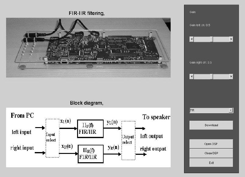
2 Digital Signal Processing ETI Introduction In the course we have 2 laboratory works for Each laboratory work is a 3 hours lesson. We will use MATLAB for illustrate some features in digital signal processing. Equipment: PC with Matlab and input/output of sound. Matlab: Matlab toolboxes: Signal Processing toolbox Data acquisition toolbox Lab 1: Lab 2: Real time spectral analysis using Fourier transform and estimation of impulse responses using correlation function Design of IIR-filters

3 Laboratory work 1: Real time spectral analysis using the Fourier transform In this laboratory work we will use MATLAB for illustrate some features in digital signal processing. Start Matlab and update the Matlab path. Connect the microphone to PC mic in connector. You can use the speakers in the PC or connect external headphones. Task 1. Real time spectral analysis using Fourier transform Start Matlab. At the Matlab prompt, type sigfftio_lin (or sigfftio_log or demoai_fft ) Now a spectrum analyzing window will be opened, see below Item 1: Say the word smile slowly and look at the spectra of the vowels i and e. Fill in the diagram below and estimate the pitch. My pitch is...(some mean value). Item 2: Try to generate a sound with as flat spectrum as possible. ( oral white noise )

4 Task 2. Real time spectrogram A spectrogram is a time-frequency plot of the signal. A sliding window is applied to the signal and the short time Fourier transform are determined for each time-window. The plot has time on the x-axis and frequency on the y-axis. See help spectrogram for more information Type N=20000; Fmax=4000; record_spectra_china % N=no of samples (Fs=10 khz), %Fmax = max freq in the plot (<5000 Hz) Now 2 seconds of mic in will be recorded and then the spectrogram will be shown. (Increase N if you want to have longer sequences) Item 1: Pronounce the Chinese words below and see if you have the correct pitch (tone). Let the Chinese students show the correct pitch. Use also some Swedish words with Chinese tone.
5 Item 2: In Swedish we have two tones (accent). Try the Swedish words A: anden, the duck (bird) B: anden, the ghost, The Swedish students have to learn the Chinese students the correct pitch. Task 3. Estimation of impulses responses using correlation Correlation functions are often used in estimation of unknown systems. This is described in the textbook pages and in the slides from the second lecture.. Input Output Relations using correlation functions (from the slides) x(n) h(n) y(n) = h(n) * x(n) Autocorrelation function for the output r yy ( l) = r ( l) r ( l) if r ( l) = h( l) h( l) Cross correlation function for input output signal r yx hh xx ( l) = h( l) r ( l) xx If the autocorrelation for the input is a delta function, r xx ( l) = δ ( l), we direct have the impulse response h( l) = ryx( l). If the autocorrelation for the input is not a delta function, we have to estimate the impulse response from the expression for the cross correlation. This is not included in this course. But still, we can find a lot of information even in this case. We will here use pre-generated signals. In files on the computer there are pairs of input and output signals from various unknown filters. Try to estimate these impulse responses. Matlab script for computing the correlation function used below. % lab_sigcorr.m Compute and plot correlation -N0<0<N0 % [rxy,n]=lab_sigcorr(x,y,n0); function [rxy,n]=lab_sigcorr(x,y,n0) Nx=length(x); Ny=length(y); if Nx==Ny N=Nx; else N=min(Nx,Ny); end rxy=xcorr(x(1:n),y(1:n)); rxy=rxy(n-n0:n+n0); n=-n0:n0; hh
6 Item 1: Music noise through an echo filter. First we listen to music through an echo filter (reverberation). We can hear the effect of the echoes but it will be difficult to estimate the time delays. The input and output signals are stored in files with input in the left channel and output in the right channel. Listen to the signals and then try to estimate the delay using correlation functions. Type the command below Load the signals and plot and listen to them. load sig_music; x=sig_music(:,1); y=sig_music(:,2); % load input and output signals soundsc(x,10000); pause(10), soundsc(y,10000); Use also the plot command to plot parts of the signals. subplot(211), plot(x), subplot(212), plot(y) % Plot input and output Now, use correlation functions to estimate the delays (the impulse response). Write type lab_sigcorr to show the Matlab code. N0=2000;[rxx,n]=lab_sigcorr(x,x,N0);plot(n,rxx);grid on % input auto correlation N0=2000;[ryx,n]=lab_sigcorr(y,x,N0);plot(n,ryx);grid on % cross correlation N0=2000;[ryy,n]=lab_sigcorr(y,y,N0);plot(n,ryy);grid on % autocorrelation Estimate the delay in the impulse response. The delays are...ms (my guess). Item 2: Use white noise as the input to the echo filter. We use white noise as the input and repeat the instructions from item 1. White noise has the correlation equal to a delta spike, i.e. the autocorrelation function for white noise is rxx(l)=δ(l). Type the command below load sig_noise; x=sig_noise(:,1);y=sig_noise(:,2); % Load input and output data Note: Decrease the pause to 4 s. soundsc(x,10000);pause(4),soundsc(y,10000); % Listen to input and output Use also the plot command to plot parts of the signals. subplot(211), plot(x), subplot(212), plot(y) % Plot input and output Now, use correlation functions to estimate the delas (impulse response). N0=2000;[rxx,n]=lab_sigcorr(x,x,N0);plot(n,rxx);grid on % input auto correlation N0=2000;[ryx,n]=lab_sigcorr(y,x,N0);plot(n,ryx);grid on % in-out cross correlation N0=2000;[ryy,n]=lab_sigcorr(y,y,N0);plot(n,ryy);grid on % output autocorrelation With white noise as input it will be easier to estimate the impulse response. The estimate the delays in the impulse response are......ms.
7 Item 3: White noise through a band pass filter. We have now estimated the impulse response of an echo filter. Next step is to estimate a band pass filter impulse response. Load the input-output signals and listen to them. Then estimate the impulse response using correlation functions. Type the command below load sig_bandpass_noise; x=sig_bandpass_noise(:,1);y=sig_bandpass_noise(:,2); soundsc(x,10000);pause(4),soundsc(y,10000); N0=2000;[rxx,n]=lab_sigcorr(x,x,N0);plot(n,rxx);grid on % input auto correlation N0=2000;[ryx,n]=lab_sigcorr(y,x,N0);plot(n,ryx);grid on % cross correlation N0=2000;[ryy,n]=lab_sigcorr(y,y,N0);plot(n,ryy);grid on % autocorrelation You can hear that the output signal is a narrow band signal. Check the spectrum by taking the Fourier transform of ryx(n) by typing sigfftp(ryx,10000,10000,1000); % plot spectra up to 1 khz, Fs=10 khz Item 4: Speech through a GSM phone We know that the signal passing through a GSM system are delayed. How much? A signal before and after passing the GSM phone is stored in a file (sample rate 10 khz). Type the command below load sig_gsm; x=sig_gsm(:,1);y=sig_gsm(:,2); soundsc(x,10000);pause(3),soundsc(y,10000); Determine the delay using the correlation functions N0=2000;[ryx,n]=lab_sigcorr(y,x,N0);plot(n,ryx);grid on % cross correlation N0=2000;[ryy,n]=lab_sigcorr(y,y,N0);plot(n,ryy);grid on % autocorrelation The delay is..ms.

8 Task 4 Speech scrambler A system shown below is often referred to as a speech scrambler. You shall test this system in Matlab. x(n) y(n) cos(2π 0.5 n)=( 1) n Test the system with sound as input. Follow the instructions below. load sig_music; x=sig_music(:,1); %load sound signal x=sig_music(:,1); N=length(x); n=[1:n]'; speech_scrambler_lab_a % speech scrambler Matlab scrip for speech scrambler %speech_scrambler_lab_a.m demo of speech scrambler bm 2011 % Use: N=20000;n=1:N;x=sin(2*pi*0.1*n); speech_scrambler_lab_a y=(-1).^n.*x; sound(0.5*x,10000);pause(10);sound(0.5*y,10000) subplot(211),sigfftp(x,1,n,1); subplot(212),sigfftp(y,1,n,1); To further analyze the system we use sinusoids as the input, x( n) = cos(2π 0.1n). Test the speech scrambler with this signal. N=4000; n=[1:n]'; x=sin(2*pi*0.1*n); speech_scrambler_lab_a Draw the spectra for x(n) and y(n) from the screen. Try to explain the results. Hint: Use the well-known formula Spectrum X(f) and Y(f). 2 sum difference cos( a ) cos( b ) = cos( a{ + b ) + cos( a{ b )
9 Task 5: SSB-modulator I all communication systems, frequency translation are used. We move information signals from low frequencies up to higher frequencies before transmission and at the receiver side we received the signal and then translate the signals back to low frequencies. This procedure is called modulation-demodulation and the equipment is called modem. We illustrate this with an SSB-modulation-demodulation system often used in communication systems. A time-discrete system is given below (SSB modulator). A x(n) B C D E Hlowpass(f) Hlowpass(f) y(n) cos(2π 0.25 n) cos(2π 0.(25 +deltaf) n) Hlow pass (f) Test this using the Matlab script below f %ssb_lab_2011.m demo of SSB-mod/demoulation bm 2011 % Use: N=20000;x=sin(2*pi*0.1*n);deltaf=0.025;,ssb % Use: N=20000;n=[1:N]'; x=sin(2*pi*0.1*n); deltaf=0;, ssb_lab_2011 % x=sig_music(:,1);n=length(x);deltaf=0.025;,ssb_lab_2011, soundsc(xe,10000); fc=.25; n=[1:n]'; hlp=fir1(500,2*.25); xa=x; xb=xa.*sin(2*pi*fc*n); xc=filter(hlp,1,xb); xd=xc.*cos(2*pi*(fc+deltaf)*n); xe=filter(hlp,1,xd); subplot(511),sigfftp(xa,1,n); subplot(512),sigfftp(xb,1,n); subplot(513),sigfftp(xc,1,n); subplot(514),sigfftp(xd,1,n); subplot(515),sigfftp(xe,1,n);
; To analyze the SSB system, we now use a sinusoids as input signal. Test first with deltaf=0 in Matlab. N=20000;n=[1:N]'; x=sin(2*pi*0.")
10 First, test with music deltaf=0 and deltaf=0.025 load sig_music; x=sig_music(:,1); soundsc(x,10000); x=sig_music(:,1);n=length(x);deltaf=0.000; ssb_lab_2011, soundsc(xe,10000); To analyze the SSB system, we now use a sinusoids as input signal. Test first with deltaf=0 in Matlab. N=20000;n=[1:N]'; x=sin(2*pi*0.1*n); deltaf=0;, ssb_lab_2011 Whats happen if deltaf is not zero. Try to draw the spectra for in the points A, B, C, D and E for delta f=0.025 in the figure below. Then check the result in Matlab using N=20000;n=[1:N]'; x=sin(2*pi*0.1*n); deltaf=0.025;, ssb_lab_2011 Explain what's happen in the SSB system for various values of deltaf.
11 Laboratory work 2: Design of IIR filters Introduction In this laboratory work we will design FIR and IIR filters. First, we will show the relation between pole-zero plots and the magnitude spectra and impulse responses for digital filters. The we will design notch filters which will be tested in both Matlab Preparation exercise 1 Combine the pole-zero plot and the magnitude spectra H(f) below. Show the pair of pole-zero plot and magnitude spectra corresponding to the same system. Pole-zero plot Magnitude spectra H(f)
12 Preparation exercise 2 Sketch the magnitude spectra H(f) for the given the pole-zero plots. Pole-zero plot Magnitude spectra H(f)

13 Laboratory tasks IIR filter The program MKIIR is used for interactive IIR filter design. You can place poles and zeros in the pole-zero plane and then show the impulse response, magnitude spectra and phase function for the digital system. The program can also design filters from specification of requirements of magnitude spectra. A set of standard filters are also included in the program. Task 1 Type MKIIR to start the program at the Matlab prompt. Place a pole or a pair of complex poles in the z plane and check the result. Press first Replace last. Move the pole inside the unit circle and check the result. Specially, look at the relation of the magnitude and angle of the poles and the magnitude spectra and the impulse response. Release Replace last.
14 Task 2 Choose poles and zeros for fulfilling the demands below based on your experience from task 1. Press Import Workspace and open the file irspec1.mat to load the specifications into MKIIR. Now, choose poles and zeros to fulfill the requirements. You can ave your filter with Export Workspace and choose a file name (i.e.filter1.mat. Then press Import filter to reload the filter. Optional task Compare with standard filter solutions. Stop the program MKIIR, press Exit. Task 3 Now, you will examine notch filters. The system function for both the FIR filter and the IIR filter are given below with ω 0 the frequency which shall be cancelled. Plot the magnitude spectra for the filters with varying position of the poles and zeros using the program MKIIR. Alternatively, you can use Matlab direct and typing your system function above (FIR). f0=0.2; r=0.95; w0=2*pi*0.2; f=0:.01:1; z=exp(j*2*pi*f); Hfir=1-2*cos(w0)*z.^(-1)+z.^(-2);subplot(211), plot(f,abs(hfir)); Hiir=Hfir./(1-2*r*cos(w0)*z.^(-1)+r^2*z.^(-2)); subplot(212),plot(f,abs(hiir));
15 Task 4 In this task, you shall cancel sinusoids added to music files. Sampling rate Fs=8000 Hz, stereo. Call global S, jukebox, song=s; and choose a song from the list. You must choose one of the first 5 for testing in the DSP. The variable S will contents samples from the song and it is stored in the variable 'song' for future use. Listen to the song (small part) soundsc(song,8000); Use Windows "Sound recorder" to listen to the whole song. Avoid long files in Matlab due to difficulties to stop the sound outputs in Matlab. Now, use MKSPA to determine the frequencies of the sinusoids. Press PEAK and use the mouse to point at peaks in the spectrum. The frequencies are multiples of 10 Hz. Write down the frequencies for the peaks of your song. Press Exit to stop MKSPA. Now, you shall determine a notch filter which cancel the sinusoids. Try both FIR and IIR filters. Type your choice of poles and zeros in Matlab and put them into vectors. Then, determine the A and B polynomials. Example: Fs=8000; F1= ; F2= ; F3= ; z1=exp(-j*2*pi*f1/fs); z2=conj(z1); z3=exp(-j*2*pi*f2/fs); z4=conj(z3); z5=exp(-j*2*pi*f3/fs); z6=conj(z5); Z=[z1,z2,z3,z4,z5,z6]; P=0.9*Z; B=poly(Z) A=poly(P) zplane(b,a) % check pole-zero plot plot also the magnitude spectrum for your filter (see help freqz) f=0:.01:1; w=2*pi*f; H=freqz(B,1,w); plot(f,abs(h)); %FIR f=0:.01:1; w=2*pi*f; H=freqz(B,A,w); plot(f,abs(h)); %IIR Notice: You must use j for the imagine part. Test the filter using MKIIR.
16 Test the filter in Matlab You have already a small part of the song in the global variable 'song'. If not, reloaded using: song=wavread('ssilence',[ ]); % load value Listen to the disturbed song (no filtering) soundsc(song, 8000); % listen Fs=8 khz Filter the song with your filters, both the FIR and the IIR filter and listen. y0=filter(b,1,song); soundsc(y0, 8000); y1=filter(b,a,song); soundsc(y1, 8000); Did your filters fulfill the requirements?
17 Appendix: Program descriptions IIR filter design, MKIIR MKIIR can be used for interactive filter design from poles and zeros. Function Import Workspace: Export Workspace: Set filter specs: Filter coeffs: Help: About: Reset: Read filter specifications from file. Save filter specifications on file. Input filter specifications. Input filter coefficients. Not implemented yet. Program version. Resets poles and zeros but not filter specifications. Exit: Exits and save workspace to the file current.mat. Add pole: Place pole, press left mouse button, ends with right mouse button. Delete pole: Add zero: Delete zero: Place cursor over pole, press left mouse button to delete, ends with right mouse button. Set Add pole See delete pole
18 Move: Import filter: Magnitude: Phase: Impulse: Replace last: Reciproc Zeros: HighPass: Zoom: Unwrap; Focus: Radius Adjust Gain: See add pole Import of standard filters from Matlab Signal Processing Toolbox. Magnitude function. Phase function. Impulse response. Replace last High pass filter H(f) _{ f=0.5}=1, Low pass filter H(f) _{ f=0}=1. Zoom. Phase Unwrap Phase. Adjust Gain in db.
: Zoom: Analyze: Exit Window functions. FFT length. Number of overlapping segments Sampling frequency.")
19 Spectral analysis, MKSPA MKSPA is used to analyze the spectra in the sound files. Functions Window: FFT length: Overlap: Fs(Hz): Zoom: Analyze: Exit Window functions. FFT length. Number of overlapping segments Sampling frequency. Activate/deactivate Matlab zoom Analyze End the program.
Digital Signal Processing ETI
 2012 Digital Signal Processing ETI265 2012 Introduction In the course we have 2 laboratory works for 2012. Each laboratory work is a 3 hours lesson. We will use MATLAB for illustrate some features in digital
Laboration Exercises in Digital Signal Processing
 Laboration Exercises in Digital Signal Processing Mikael Swartling Department of Electrical and Information Technology Lund Institute of Technology revision 215 Introduction Introduction The traditional
Electrical & Computer Engineering Technology
 Electrical & Computer Engineering Technology EET 419C Digital Signal Processing Laboratory Experiments by Masood Ejaz Experiment # 1 Quantization of Analog Signals and Calculation of Quantized noise Objective:
DSP First. Laboratory Exercise #7. Everyday Sinusoidal Signals
 DSP First Laboratory Exercise #7 Everyday Sinusoidal Signals This lab introduces two practical applications where sinusoidal signals are used to transmit information: a touch-tone dialer and amplitude
Lab S-9: Interference Removal from Electro-Cardiogram (ECG) Signals
 Signals") DSP First, 2e Signal Processing First Lab S-9: Interference Removal from Electro-Cardiogram (ECG) Signals Pre-Lab: Read the Pre-Lab and do all the exercises in the Pre-Lab section prior to attending lab.
DSP First, 2e Signal Processing First Lab S-9: Interference Removal from Electro-Cardiogram (ECG) Signals Pre-Lab: Read the Pre-Lab and do all the exercises in the Pre-Lab section prior to attending lab.
ECE438 - Laboratory 7a: Digital Filter Design (Week 1) By Prof. Charles Bouman and Prof. Mireille Boutin Fall 2015
 By Prof. Charles Bouman and Prof. Mireille Boutin Fall 2015") Purdue University: ECE438 - Digital Signal Processing with Applications 1 ECE438 - Laboratory 7a: Digital Filter Design (Week 1) By Prof. Charles Bouman and Prof. Mireille Boutin Fall 2015 1 Introduction
Purdue University: ECE438 - Digital Signal Processing with Applications 1 ECE438 - Laboratory 7a: Digital Filter Design (Week 1) By Prof. Charles Bouman and Prof. Mireille Boutin Fall 2015 1 Introduction
1 PeZ: Introduction. 1.1 Controls for PeZ using pezdemo. Lab 15b: FIR Filter Design and PeZ: The z, n, and O! Domains
 DSP First, 2e Signal Processing First Lab 5b: FIR Filter Design and PeZ: The z, n, and O! Domains The lab report/verification will be done by filling in the last page of this handout which addresses a
DFT: Discrete Fourier Transform & Linear Signal Processing
 DFT: Discrete Fourier Transform & Linear Signal Processing 2 nd Year Electronics Lab IMPERIAL COLLEGE LONDON Table of Contents Equipment... 2 Aims... 2 Objectives... 2 Recommended Textbooks... 3 Recommended
ijdsp Workshop: Exercise 2012 DSP Exercise Objectives
 Objectives DSP Exercise The objective of this exercise is to provide hands-on experiences on ijdsp. It consists of three parts covering frequency response of LTI systems, pole/zero locations with the frequency
GEORGIA INSTITUTE OF TECHNOLOGY. SCHOOL of ELECTRICAL and COMPUTER ENGINEERING. ECE 2026 Summer 2018 Lab #8: Filter Design of FIR Filters
 GEORGIA INSTITUTE OF TECHNOLOGY SCHOOL of ELECTRICAL and COMPUTER ENGINEERING ECE 2026 Summer 2018 Lab #8: Filter Design of FIR Filters Date: 19. Jul 2018 Pre-Lab: You should read the Pre-Lab section of
Filters. Phani Chavali
 Filters Phani Chavali Filters Filtering is the most common signal processing procedure. Used as echo cancellers, equalizers, front end processing in RF receivers Used for modifying input signals by passing
ESE531 Spring University of Pennsylvania Department of Electrical and System Engineering Digital Signal Processing
 University of Pennsylvania Department of Electrical and System Engineering Digital Signal Processing ESE531, Spring 2017 Final Project: Audio Equalization Wednesday, Apr. 5 Due: Tuesday, April 25th, 11:59pm
Project 2 - Speech Detection with FIR Filters
 Project 2 - Speech Detection with FIR Filters ECE505, Fall 2015 EECS, University of Tennessee (Due 10/30) 1 Objective The project introduces a practical application where sinusoidal signals are used to
ELEC3104: Digital Signal Processing Session 1, 2013 LABORATORY 3: IMPULSE RESPONSE, FREQUENCY RESPONSE AND POLES/ZEROS OF SYSTEMS
 ELEC3104: Digital Signal Processing Session 1, 2013 The University of New South Wales School of Electrical Engineering and Telecommunications LABORATORY 3: IMPULSE RESPONSE, FREQUENCY RESPONSE AND POLES/ZEROS
EE 422G - Signals and Systems Laboratory
 EE 422G - Signals and Systems Laboratory Lab 3 FIR Filters Written by Kevin D. Donohue Department of Electrical and Computer Engineering University of Kentucky Lexington, KY 40506 September 19, 2015 Objectives:
Lecture 3, Multirate Signal Processing
 Lecture 3, Multirate Signal Processing Frequency Response If we have coefficients of an Finite Impulse Response (FIR) filter h, or in general the impulse response, its frequency response becomes (using
Lab 6: Sampling, Convolution, and FIR Filtering
 Lab 6: Sampling, Convolution, and FIR Filtering Pre-Lab and Warm-Up: You should read at least the Pre-Lab and Warm-up sections of this lab assignment and go over all exercises in the Pre-Lab section prior
Sound synthesis with Pure Data
 Sound synthesis with Pure Data 1. Start Pure Data from the programs menu in classroom TC307. You should get the following window: The DSP check box switches sound output on and off. Getting sound out First,
Signal Processing. Introduction
 Signal Processing 0 Introduction One of the premiere uses of MATLAB is in the analysis of signal processing and control systems. In this chapter we consider signal processing. The final chapter of the
Discrete-Time Signal Processing (DTSP) v14
 v14") EE 392 Laboratory 5-1 Discrete-Time Signal Processing (DTSP) v14 Safety - Voltages used here are less than 15 V and normally do not present a risk of shock. Objective: To study impulse response and the
EE 392 Laboratory 5-1 Discrete-Time Signal Processing (DTSP) v14 Safety - Voltages used here are less than 15 V and normally do not present a risk of shock. Objective: To study impulse response and the
THE HONG KONG POLYTECHNIC UNIVERSITY Department of Electronic and Information Engineering. EIE2106 Signal and System Analysis Lab 2 Fourier series
 THE HONG KONG POLYTECHNIC UNIVERSITY Department of Electronic and Information Engineering EIE2106 Signal and System Analysis Lab 2 Fourier series 1. Objective The goal of this laboratory exercise is to
Fourier Series and Gibbs Phenomenon
 Fourier Series and Gibbs Phenomenon University Of Washington, Department of Electrical Engineering This work is produced by The Connexions Project and licensed under the Creative Commons Attribution License
L A B 3 : G E N E R A T I N G S I N U S O I D S
 L A B 3 : G E N E R A T I N G S I N U S O I D S NAME: DATE OF EXPERIMENT: DATE REPORT SUBMITTED: 1/7 1 THEORY DIGITAL SIGNAL PROCESSING LABORATORY 1.1 GENERATION OF DISCRETE TIME SINUSOIDAL SIGNALS IN
EEL 4350 Principles of Communication Project 2 Due Tuesday, February 10 at the Beginning of Class
 EEL 4350 Principles of Communication Project 2 Due Tuesday, February 10 at the Beginning of Class Description In this project, MATLAB and Simulink are used to construct a system experiment. The experiment
Adaptive Filters Application of Linear Prediction
 Adaptive Filters Application of Linear Prediction Gerhard Schmidt Christian-Albrechts-Universität zu Kiel Faculty of Engineering Electrical Engineering and Information Technology Digital Signal Processing
EEO 401 Digital Signal Processing Prof. Mark Fowler
 EEO 41 Digital Signal Processing Prof. Mark Fowler Note Set #17.5 MATLAB Examples Reading Assignment: MATLAB Tutorial on Course Webpage 1/24 Folder Navigation Current folder name here Type commands here
George Mason University Signals and Systems I Spring 2016
 George Mason University Signals and Systems I Spring 2016 Laboratory Project #4 Assigned: Week of March 14, 2016 Due Date: Laboratory Section, Week of April 4, 2016 Report Format and Guidelines for Laboratory
Signal Processing for Speech Applications - Part 2-1. Signal Processing For Speech Applications - Part 2
 Signal Processing for Speech Applications - Part 2-1 Signal Processing For Speech Applications - Part 2 May 14, 2013 Signal Processing for Speech Applications - Part 2-2 References Huang et al., Chapter
SMS045 - DSP Systems in Practice. Lab 1 - Filter Design and Evaluation in MATLAB Due date: Thursday Nov 13, 2003
 SMS045 - DSP Systems in Practice Lab 1 - Filter Design and Evaluation in MATLAB Due date: Thursday Nov 13, 2003 Lab Purpose This lab will introduce MATLAB as a tool for designing and evaluating digital
EGR 111 Audio Processing
 EGR 111 Audio Processing This lab shows how to load, play, create, and filter sounds and music with MATLAB. Resources (available on course website): speech1.wav, birds_jet_noise.wav New MATLAB commands:
EE 464 Short-Time Fourier Transform Fall and Spectrogram. Many signals of importance have spectral content that
 EE 464 Short-Time Fourier Transform Fall 2018 Read Text, Chapter 4.9. and Spectrogram Many signals of importance have spectral content that changes with time. Let xx(nn), nn = 0, 1,, NN 1 1 be a discrete-time
STANFORD UNIVERSITY. DEPARTMENT of ELECTRICAL ENGINEERING. EE 102B Spring 2013 Lab #05: Generating DTMF Signals
 STANFORD UNIVERSITY DEPARTMENT of ELECTRICAL ENGINEERING EE 102B Spring 2013 Lab #05: Generating DTMF Signals Assigned: May 3, 2013 Due Date: May 17, 2013 Remember that you are bound by the Stanford University
Lab P-4: AM and FM Sinusoidal Signals. We have spent a lot of time learning about the properties of sinusoidal waveforms of the form: ) X
 X") DSP First, 2e Signal Processing First Lab P-4: AM and FM Sinusoidal Signals Pre-Lab and Warm-Up: You should read at least the Pre-Lab and Warm-up sections of this lab assignment and go over all exercises
DSP First, 2e Signal Processing First Lab P-4: AM and FM Sinusoidal Signals Pre-Lab and Warm-Up: You should read at least the Pre-Lab and Warm-up sections of this lab assignment and go over all exercises
LABORATORY - FREQUENCY ANALYSIS OF DISCRETE-TIME SIGNALS
 LABORATORY - FREQUENCY ANALYSIS OF DISCRETE-TIME SIGNALS INTRODUCTION The objective of this lab is to explore many issues involved in sampling and reconstructing signals, including analysis of the frequency
Outline. J-DSP Overview. Objectives and Motivation. by Andreas Spanias Arizona State University
 Outline JAVA-DSP () A DSP SOFTWARE TOOL FOR ON-LINE SIMULATIONS AND COMPUTER LABORATORIES by Andreas Spanias Arizona State University Sponsored by NSF-DUE-CCLI-080975-2000-04 New NSF Program Award Starts
Filter Banks I. Prof. Dr. Gerald Schuller. Fraunhofer IDMT & Ilmenau University of Technology Ilmenau, Germany. Fraunhofer IDMT
 Filter Banks I Prof. Dr. Gerald Schuller Fraunhofer IDMT & Ilmenau University of Technology Ilmenau, Germany 1 Structure of perceptual Audio Coders Encoder Decoder 2 Filter Banks essential element of most
C.8 Comb filters 462 APPENDIX C. LABORATORY EXERCISES
 462 APPENDIX C. LABORATORY EXERCISES C.8 Comb filters The purpose of this lab is to use a kind of filter called a comb filter to deeply explore concepts of impulse response and frequency response. The
Electrical and Telecommunication Engineering Technology NEW YORK CITY COLLEGE OF TECHNOLOGY THE CITY UNIVERSITY OF NEW YORK
 NEW YORK CITY COLLEGE OF TECHNOLOGY THE CITY UNIVERSITY OF NEW YORK DEPARTMENT: Electrical and Telecommunication Engineering Technology SUBJECT CODE AND TITLE: DESCRIPTION: REQUIRED TCET 4202 Advanced
EXPERIMENT 4 INTRODUCTION TO AMPLITUDE MODULATION SUBMITTED BY
 EXPERIMENT 4 INTRODUCTION TO AMPLITUDE MODULATION SUBMITTED BY NAME:. STUDENT ID:.. ROOM: INTRODUCTION TO AMPLITUDE MODULATION Purpose: The objectives of this laboratory are:. To introduce the spectrum
The University of Texas at Austin Dept. of Electrical and Computer Engineering Midterm #1
 The University of Texas at Austin Dept. of Electrical and Computer Engineering Midterm #1 Date: October 18, 2013 Course: EE 445S Evans Name: Last, First The exam is scheduled to last 50 minutes. Open books
Introduction to Simulink
 EE 460 Introduction to Communication Systems MATLAB Tutorial #3 Introduction to Simulink This tutorial provides an overview of Simulink. It also describes the use of the FFT Scope and the filter design
Lab S-4: Convolution & FIR Filters. Please read through the information below prior to attending your lab.
 DSP First, 2e Signal Processing First Lab S-4: Convolution & FIR Filters Pre-Lab: Read the Pre-Lab and do all the exercises in the Pre-Lab section prior to attending lab. Verification: The Exercise section
ece 429/529 digital signal processing robin n. strickland ece dept, university of arizona ECE 429/529 RNS
 ece 429/529 digital signal processing robin n. strickland ece dept, university of arizona 2007 SPRING 2007 SCHEDULE All dates are tentative. Lesson Day Date Learning outcomes to be Topics Textbook HW/PROJECT
Subtractive Synthesis. Describing a Filter. Filters. CMPT 468: Subtractive Synthesis
 Subtractive Synthesis CMPT 468: Subtractive Synthesis Tamara Smyth, tamaras@cs.sfu.ca School of Computing Science, Simon Fraser University November, 23 Additive synthesis involves building the sound by
Signal Processing Toolbox
 Signal Processing Toolbox Perform signal processing, analysis, and algorithm development Signal Processing Toolbox provides industry-standard algorithms for analog and digital signal processing (DSP).
Biomedical Signals. Signals and Images in Medicine Dr Nabeel Anwar
 Biomedical Signals Signals and Images in Medicine Dr Nabeel Anwar Noise Removal: Time Domain Techniques 1. Synchronized Averaging (covered in lecture 1) 2. Moving Average Filters (today s topic) 3. Derivative
Lab 4 Fourier Series and the Gibbs Phenomenon
 Lab 4 Fourier Series and the Gibbs Phenomenon EE 235: Continuous-Time Linear Systems Department of Electrical Engineering University of Washington This work 1 was written by Amittai Axelrod, Jayson Bowen,
Project 0: Part 2 A second hands-on lab on Speech Processing Frequency-domain processing
 Project : Part 2 A second hands-on lab on Speech Processing Frequency-domain processing February 24, 217 During this lab, you will have a first contact on frequency domain analysis of speech signals. You
Adaptive Systems Homework Assignment 3
 Signal Processing and Speech Communication Lab Graz University of Technology Adaptive Systems Homework Assignment 3 The analytical part of your homework (your calculation sheets) as well as the MATLAB
Memorial University of Newfoundland Faculty of Engineering and Applied Science. Lab Manual
 Memorial University of Newfoundland Faculty of Engineering and Applied Science Engineering 6871 Communication Principles Lab Manual Fall 2014 Lab 1 AMPLITUDE MODULATION Purpose: 1. Learn how to use Matlab
Lab 8. Signal Analysis Using Matlab Simulink
 E E 2 7 5 Lab June 30, 2006 Lab 8. Signal Analysis Using Matlab Simulink Introduction The Matlab Simulink software allows you to model digital signals, examine power spectra of digital signals, represent
Contents. Introduction 1 1 Suggested Reading 2 2 Equipment and Software Tools 2 3 Experiment 2
 ECE363, Experiment 02, 2018 Communications Lab, University of Toronto Experiment 02: Noise Bruno Korst - bkf@comm.utoronto.ca Abstract This experiment will introduce you to some of the characteristics
Laboratory Assignment 2 Signal Sampling, Manipulation, and Playback
 Laboratory Assignment 2 Signal Sampling, Manipulation, and Playback PURPOSE This lab will introduce you to the laboratory equipment and the software that allows you to link your computer to the hardware.
EE 470 Signals and Systems
 EE 470 Signals and Systems 9. Introduction to the Design of Discrete Filters Prof. Yasser Mostafa Kadah Textbook Luis Chapparo, Signals and Systems Using Matlab, 2 nd ed., Academic Press, 2015. Filters
ELT COMMUNICATION THEORY
 ELT 41307 COMMUNICATION THEORY Matlab Exercise #1 Sampling, Fourier transform, Spectral illustrations, and Linear filtering 1 SAMPLING The modeled signals and systems in this course are mostly analog (continuous
Armstrong Atlantic State University Engineering Studies MATLAB Marina Sound Processing Primer
 Armstrong Atlantic State University Engineering Studies MATLAB Marina Sound Processing Primer Prerequisites The Sound Processing Primer assumes knowledge of the MATLAB IDE, MATLAB help, arithmetic operations,
DSP Laboratory (EELE 4110) Lab#10 Finite Impulse Response (FIR) Filters
 Lab#10 Finite Impulse Response (FIR) Filters") Islamic University of Gaza OBJECTIVES: Faculty of Engineering Electrical Engineering Department Spring-2011 DSP Laboratory (EELE 4110) Lab#10 Finite Impulse Response (FIR) Filters To demonstrate the concept
Islamic University of Gaza OBJECTIVES: Faculty of Engineering Electrical Engineering Department Spring-2011 DSP Laboratory (EELE 4110) Lab#10 Finite Impulse Response (FIR) Filters To demonstrate the concept
ELEC3104: Digital Signal Processing Session 1, 2013
 ELEC3104: Digital Signal Processing Session 1, 2013 The University of New South Wales School of Electrical Engineering and Telecommunications LABORATORY 4: DIGITAL FILTERS INTRODUCTION In this laboratory,
Brief Introduction to Signals & Systems. Phani Chavali
 Brief Introduction to Signals & Systems Phani Chavali Outline Signals & Systems Continuous and discrete time signals Properties of Systems Input- Output relation : Convolution Frequency domain representation
1. In the command window, type "help conv" and press [enter]. Read the information displayed.
![1. In the command window, type help conv and press [enter]. Read the information displayed.](/thumbs/82/86785923.jpg "1. In the command window, type help conv and press [enter]. Read the information displayed.") ECE 317 Experiment 0 The purpose of this experiment is to understand how to represent signals in MATLAB, perform the convolution of signals, and study some simple LTI systems. Please answer all questions
ECE 317 Experiment 0 The purpose of this experiment is to understand how to represent signals in MATLAB, perform the convolution of signals, and study some simple LTI systems. Please answer all questions
Lab 6 - MCU CODEC IIR Filter ReadMeFirst
 Lab 6 - MCU CODEC IIR Filter ReadMeFirst Lab Summary In this lab you will use a microcontroller and an audio CODEC to design a 2nd order low pass digital IIR filter. Use this filter to remove the noise
Creating Digital Music
 Chapter 2 Creating Digital Music Chapter 2 exposes students to some of the most important engineering ideas associated with the creation of digital music. Students learn how basic ideas drawn from the
EE 5410 Signal Processing
 EE 54 Signal Processing MATLAB Exercise Telephone Touch-Tone Signal Encoding and Decoding Intended Learning Outcomes: On completion of this MATLAB laboratory exercise, you should be able to Generate and
DSP First Lab 03: AM and FM Sinusoidal Signals. We have spent a lot of time learning about the properties of sinusoidal waveforms of the form: k=1
 DSP First Lab 03: AM and FM Sinusoidal Signals Pre-Lab and Warm-Up: You should read at least the Pre-Lab and Warm-up sections of this lab assignment and go over all exercises in the Pre-Lab section before
2.161 Signal Processing: Continuous and Discrete Fall 2008
 MIT OpenCourseWare http://ocw.mit.edu 2.161 Signal Processing: Continuous and Discrete Fall 28 For information about citing these materials or our Terms of Use, visit: http://ocw.mit.edu/terms. Massachusetts
Figure 1: Block diagram of Digital signal processing
 Experiment 3. Digital Process of Continuous Time Signal. Introduction Discrete time signal processing algorithms are being used to process naturally occurring analog signals (like speech, music and images).
Multirate Signal Processing Lecture 7, Sampling Gerald Schuller, TU Ilmenau
 Multirate Signal Processing Lecture 7, Sampling Gerald Schuller, TU Ilmenau (Also see: Lecture ADSP, Slides 06) In discrete, digital signal we use the normalized frequency, T = / f s =: it is without a
ADSP ADSP ADSP ADSP. Advanced Digital Signal Processing (18-792) Spring Fall Semester, Department of Electrical and Computer Engineering
 Spring Fall Semester, Department of Electrical and Computer Engineering") ADSP ADSP ADSP ADSP Advanced Digital Signal Processing (18-792) Spring Fall Semester, 201 2012 Department of Electrical and Computer Engineering PROBLEM SET 5 Issued: 9/27/18 Due: 10/3/18 Reminder: Quiz
ADSP ADSP ADSP ADSP Advanced Digital Signal Processing (18-792) Spring Fall Semester, 201 2012 Department of Electrical and Computer Engineering PROBLEM SET 5 Issued: 9/27/18 Due: 10/3/18 Reminder: Quiz
Lab 4 An FPGA Based Digital System Design ReadMeFirst
 Lab 4 An FPGA Based Digital System Design ReadMeFirst Lab Summary This Lab introduces a number of Matlab functions used to design and test a lowpass IIR filter. As you have seen in the previous lab, Simulink
ECE 5650/4650 Exam II November 20, 2018 Name:
 ECE 5650/4650 Exam II November 0, 08 Name: Take-Home Exam Honor Code This being a take-home exam a strict honor code is assumed. Each person is to do his/her own work. Bring any questions you have about
AC : INTERACTIVE LEARNING DISCRETE TIME SIGNALS AND SYSTEMS WITH MATLAB AND TI DSK6713 DSP KIT
 AC 2007-2807: INTERACTIVE LEARNING DISCRETE TIME SIGNALS AND SYSTEMS WITH MATLAB AND TI DSK6713 DSP KIT Zekeriya Aliyazicioglu, California State Polytechnic University-Pomona Saeed Monemi, California State
ECE 5655/4655 Laboratory Problems
 Assignment #5 ECE 5655/4655 Laboratory Problems Make Note of the Following: Due MondayApril 29, 2019 If possible write your lab report in Jupyter notebook If you choose to use the spectrum/network analyzer
Limitations of Sum-of-Sinusoid Signals
 Limitations of Sum-of-Sinusoid Signals I So far, we have considered only signals that can be written as a sum of sinusoids. x(t) =A 0 + N Â A i cos(2pf i t + f i ). i=1 I For such signals, we are able
Project 2. Project 2: audio equalizer. Fig. 1: Kinter MA-170 stereo amplifier with bass and treble controls.
 Introduction Project 2 Project 2: audio equalizer This project aims to motivate our study o ilters by considering the design and implementation o an audio equalizer. An equalizer (EQ) modiies the requency
EE477 Digital Signal Processing Laboratory Exercise #13
 EE477 Digital Signal Processing Laboratory Exercise #13 Real time FIR filtering Spring 2004 The object of this lab is to implement a C language FIR filter on the SHARC evaluation board. We will filter
Islamic University of Gaza. Faculty of Engineering Electrical Engineering Department Spring-2011
 Islamic University of Gaza Faculty of Engineering Electrical Engineering Department Spring-2011 DSP Laboratory (EELE 4110) Lab#4 Sampling and Quantization OBJECTIVES: When you have completed this assignment,
ECE 5650/4650 Computer Project #3 Adaptive Filter Simulation
 ECE 5650/4650 Computer Project #3 Adaptive Filter Simulation This project is to be treated as a take-home exam, meaning each student is to due his/her own work without consulting others. The grading for
Concordia University. Discrete-Time Signal Processing. Lab Manual (ELEC442) Dr. Wei-Ping Zhu
 Dr. Wei-Ping Zhu") Concordia University Discrete-Time Signal Processing Lab Manual (ELEC442) Course Instructor: Dr. Wei-Ping Zhu Fall 2012 Lab 1: Linear Constant Coefficient Difference Equations (LCCDE) Objective In this
Concordia University Discrete-Time Signal Processing Lab Manual (ELEC442) Course Instructor: Dr. Wei-Ping Zhu Fall 2012 Lab 1: Linear Constant Coefficient Difference Equations (LCCDE) Objective In this
B.Tech III Year II Semester (R13) Regular & Supplementary Examinations May/June 2017 DIGITAL SIGNAL PROCESSING (Common to ECE and EIE)
 Regular & Supplementary Examinations May/June 2017 DIGITAL SIGNAL PROCESSING (Common to ECE and EIE)") Code: 13A04602 R13 B.Tech III Year II Semester (R13) Regular & Supplementary Examinations May/June 2017 (Common to ECE and EIE) PART A (Compulsory Question) 1 Answer the following: (10 X 02 = 20 Marks)
Code: 13A04602 R13 B.Tech III Year II Semester (R13) Regular & Supplementary Examinations May/June 2017 (Common to ECE and EIE) PART A (Compulsory Question) 1 Answer the following: (10 X 02 = 20 Marks)
The University of Queensland School of Information Technology and Electrical Engineering. ELEC3004/7312: Signals, Systems and Controls
 The University of Queensland School of Information Technology and Electrical Engineering ELEC3004/7312: Signals, Systems and Controls EXPERIMENT 3: ECHO FILTERS ON THE NEXYS 2 Aims In this laboratory session
Lab 15c: Cochlear Implant Simulation with a Filter Bank
 DSP First, 2e Signal Processing First Lab 15c: Cochlear Implant Simulation with a Filter Bank Pre-Lab and Warm-Up: You should read at least the Pre-Lab and Warm-up sections of this lab assignment and go
ECE 5650/4650 MATLAB Project 1
 This project is to be treated as a take-home exam, meaning each student is to due his/her own work. The project due date is 4:30 PM Tuesday, October 18, 2011. To work the project you will need access to
8A. ANALYSIS OF COMPLEX SOUNDS. Amplitude, loudness, and decibels
 8A. ANALYSIS OF COMPLEX SOUNDS Amplitude, loudness, and decibels Last week we found that we could synthesize complex sounds with a particular frequency, f, by adding together sine waves from the harmonic
ECEn 487 Digital Signal Processing Laboratory. Lab 3 FFT-based Spectrum Analyzer
 ECEn 487 Digital Signal Processing Laboratory Lab 3 FFT-based Spectrum Analyzer Due Dates This is a three week lab. All TA check off must be completed by Friday, March 14, at 3 PM or the lab will be marked
ELEC-C5230 Digitaalisen signaalinkäsittelyn perusteet
 ELEC-C5230 Digitaalisen signaalinkäsittelyn perusteet Lecture 10: Summary Taneli Riihonen 16.05.2016 Lecture 10 in Course Book Sanjit K. Mitra, Digital Signal Processing: A Computer-Based Approach, 4th
Signal processing preliminaries
 Signal processing preliminaries ISMIR Graduate School, October 4th-9th, 2004 Contents: Digital audio signals Fourier transform Spectrum estimation Filters Signal Proc. 2 1 Digital signals Advantages of
Basic Signals and Systems
 Chapter 2 Basic Signals and Systems A large part of this chapter is taken from: C.S. Burrus, J.H. McClellan, A.V. Oppenheim, T.W. Parks, R.W. Schafer, and H. W. Schüssler: Computer-based exercises for
University of Bahrain
 University of Bahrain College of Engineering Dept of Electrical and Electronics Engineering Experiment 5 EEG 453 Multimedia Audio processing Objectives This experiment demonstrates different Audio processing
1. page xviii, line 23:... conventional. Part of the reason for this...
 DSP First ERRATA. These are mostly typos, double words, misspellings, etc. Underline is not used in the book, so I ve used it to denote changes. JMcClellan, February 22, 2002 1. page xviii, line 23:...
EE 3054: Signals, Systems, and Transforms Lab Manual
 EE 3054: Signals, Systems, and Transforms Lab Manual 1. The lab will meet every week. 2. Be sure to review the lab ahead of the lab session. Please ask questions of the TA s if you need some help, but
George Mason University ECE 201: Introduction to Signal Analysis Spring 2017
 Assigned: March 7, 017 Due Date: Week of April 10, 017 George Mason University ECE 01: Introduction to Signal Analysis Spring 017 Laboratory Project #7 Due Date Your lab report must be submitted on blackboard
NAME STUDENT # ELEC 484 Audio Signal Processing. Midterm Exam July Listening test
 NAME STUDENT # ELEC 484 Audio Signal Processing Midterm Exam July 2008 CLOSED BOOK EXAM Time 1 hour Listening test Choose one of the digital audio effects for each sound example. Put only ONE mark in each
EECS 452 Midterm Exam Winter 2012
 EECS 452 Midterm Exam Winter 2012 Name: unique name: Sign the honor code: I have neither given nor received aid on this exam nor observed anyone else doing so. Scores: # Points Section I /40 Section II
Lab 3 FFT based Spectrum Analyzer
 ECEn 487 Digital Signal Processing Laboratory Lab 3 FFT based Spectrum Analyzer Due Dates This is a three week lab. All TA check off must be completed prior to the beginning of class on the lab book submission
Jawaharlal Nehru Engineering College
 Jawaharlal Nehru Engineering College Laboratory Manual SIGNALS & SYSTEMS For Third Year Students Prepared By: Ms.Sunetra S Suvarna Assistant Professor Author JNEC INSTRU. & CONTROL DEPT., Aurangabad SUBJECT
Digital Video and Audio Processing. Winter term 2002/ 2003 Computer-based exercises
 Digital Video and Audio Processing Winter term 2002/ 2003 Computer-based exercises Rudolf Mester Institut für Angewandte Physik Johann Wolfgang Goethe-Universität Frankfurt am Main 6th November 2002 Chapter
Massachusetts Institute of Technology Dept. of Electrical Engineering and Computer Science Spring Semester, Introduction to EECS 2
 Massachusetts Institute of Technology Dept. of Electrical Engineering and Computer Science Spring Semester, 2007 6.082 Introduction to EECS 2 Lab #3: Modulation and Filtering Goal:... 2 Instructions:...
George Mason University ECE 201: Introduction to Signal Analysis
 Due Date: Week of May 01, 2017 1 George Mason University ECE 201: Introduction to Signal Analysis Computer Project Part II Project Description Due to the length and scope of this project, it will be broken
Discrete Fourier Transform (DFT)
") Amplitude Amplitude Discrete Fourier Transform (DFT) DFT transforms the time domain signal samples to the frequency domain components. DFT Signal Spectrum Time Frequency DFT is often used to do frequency
Amplitude Amplitude Discrete Fourier Transform (DFT) DFT transforms the time domain signal samples to the frequency domain components. DFT Signal Spectrum Time Frequency DFT is often used to do frequency
Spring 2018 EE 445S Real-Time Digital Signal Processing Laboratory Prof. Evans. Homework #1 Sinusoids, Transforms and Transfer Functions
 Spring 2018 EE 445S Real-Time Digital Signal Processing Laboratory Prof. Homework #1 Sinusoids, Transforms and Transfer Functions Assigned on Friday, February 2, 2018 Due on Friday, February 9, 2018, by