A RADIO TEST REPORT FOR. MICROWAVE SOLUTIONS Ltd X-BAND DOPPLER MOTION DETECTOR UNITS MODEL NUMBER MDU1720 DOCUMENT NO.
|
|
|
- Tyrone Welch
- 6 years ago
- Views:
Transcription
1 A RADIO TEST REPORT FOR MICROWAVE SOLUTIONS Ltd ON X-BAND DOPPLER MOTION DETECTOR UNITS MODEL NUMBER MDU1720 DOCUMENT NO. TRA W-NA-1

2 TRaC Wireless Test Report : TRA W-NA-1 Applicant : Microwave Solutions Ltd Apparatus : MDU1720 Specification(s) : CFR47 Part 15 & RSS-210 Purpose of Test : Limited Modular Approval FCCID : ROO-MDU1720 Certification Number : 10829A-MDU1720 Authorised by : : Radio Product Manager Issue Date : 18 th January 2013 Authorised Copy Number : PDF Total number of pages: 40
3 Contents Section 1: Introduction General Tests Requested By Manufacturer Apparatus Assessed Test Result Summary Notes Relating To The Assessment Deviations from Test Standards 7 Section 2: Measurement Uncertainty Measurement Uncertainty Values 8 Section 3: Modifications Modifications Performed During Assessment 10 Appendix A: Formal Emission Test Results 11 A1 Transmitter Intentional Emission Radiated 12 A2 Radiated Electric Field Emissions 14 A3 Power Line Conducted Emissions 17 Appendix B: Supporting Graphical Data 19 Appendix C: Additional Test and Sample Details 27 Appendix D: Additional Information 33 Appendix E: Calculation of the duty cycle correction factor 34 Appendix F: Photographs and Figures 35 Appendix G: MPE Calculation 39 3
4 Section 1: Introduction 1.1 General This report contains an assessment of an apparatus against Electromagnetic Compatibility Standards based upon tests carried out on samples submitted to the Laboratory. Test performed by: TRaC Global [ ] Unit E South Orbital Trading Park Hedon Road Hull, HU9 1NJ. United Kingdom. Telephone: +44 (0) Fax: +44 (0) TRaC Global Unit 1 Pendle Place Skelmersdale West Lancashire, WN8 9PN United Kingdom [X] Telephone: +44 (0) Fax: +44 (0) Web site: test@tracglobal.com Tests performed by: D. Winstanley Report author: D. Winstanley This report must not be reproduced except in full without prior written permission from TRaC Global. 4
5 1.2 Tests Requested By This testing in this report was requested by : Microwave Solutions Ltd Hamilton House 111 Marlowes Hemel Hempstead Herts HP1 1BB UNITED KINGDOM 1.3 Manufacturer As Above 1.4 Apparatus Assessed The following apparatus was assessed between the dates 4 th 19 th December 2012: X-Band Doppler Motion Detector Unit Model Number MDU1720 The unit is able to operate at 100% transmitter on mode or in a pulsed mode with a duty cycle down to 1% The MDU1720 is a module. This assessment of the MDU1720 covers use in both indoor and outdoor applications. 5
6 1.5 Test Result Summary Full details of test results are contained within Appendix A. The following table summarises the results of the assessment. The statements relating to compliance with the standards below apply ONLY as qualified in the notes and deviations stated in sections 1.6 to 1.7 of this test report. Full details of test results are contained within Appendix A. The following table summarises the results of the assessment. Test Type Title 47 of the CFR: Part 15 Subpart (c) Regulation RSS-210 Section Measurement standard Result Spurious Emissions Radiated <1000MHz RSS-Gen 4.9 RSS-210 Annex 7 ANSI C63.10:2009 Pass Spurious Emissions Radiated >1000MHz & RSS-Gen 4.9 RSS-210 Annex 7 ANSI C63.10:2009 Pass AC Power conducted emissions & RSS-Gen Issue ANSI C63.10:2009 Pass Intentional Emission Frequency RSS-210 Annex 7 ANSI C63.10:2009 Pass Intentional Emission Field Strength RSS-210 Annex 7 ANSI C63.10:2009 Pass Intentional Emission Band Occupancy RSS-Gen Issue ANSI C63.10:2009 Pass Intentional Emission ERP (mw) - - ANSI C63.10: Unintentional Radiated Spurious Emissions RSS-Gen Issue ANSI C63.10:2009 Pass Antenna Arrangements Integral: RSS-Gen Issue Pass Antenna Arrangements External Connector RSS-Gen Issue Restricted Bands RSS-Gen Issue Maximum Frequency of Search RSS-Gen Issue Extrapolation Factor 15.35(f) Abbreviations used in the above table: RSS-Gen Issue ANSI C 63.10:2009 is outside the scope of the laboratories UKAS accreditation. CFR : Code of Federal Regulations ANSI : American National Standards Institution RSS : Radio Standards Specification PLCE : Power Line Conducted Emissions 6
7 1.6 Notes Relating To The Assessment With regard to this assessment, the following points should be noted: The results contained in this report relate only to the items tested and were obtained in the period between the date of initial receipt of samples and the date of issue of the report. The apparatus was set up and exercised using the configurations, modes of operation and arrangements defined in this report only. Particular operating modes, apparatus monitoring methods and performance criteria required by the standards tested to have been performed except where identified in Section 1.7 of this test report (Deviations from Test Standards). For emissions testing, throughout this test report, Pass indicates that the results for the sample as tested were below the specified limit (refer also to Section 2, Measurement Uncertainty). Where relevant, the apparatus was only assessed using the monitoring methods and susceptibility criteria defined in this report. All testing with the exception of testing at the Open Area Test Site was performed under the following environmental conditions: Temperature : 17 to 23 C Humidity : 45 to 75 % Barometric Pressure : 86 to 106 kpa All dates used in this report are in the format dd/mm/yy. This assessment has been performed in accordance with the requirements of ISO/IEC Deviations from Test Standards There were no deviations from the standards tested to. 7
8 Section 2: Measurement Uncertainty 2.1 Measurement Uncertainty Values For the test data recorded in accordance with note (iii) of Section 2.1 the following measurement uncertainty was calculated: Radio Testing General Uncertainty Schedule All statements of uncertainty are expanded standard uncertainty using a coverage factor of 1.96 to give a 95% confidence where no required test level exists. [1] Adjacent Channel Power Uncertainty in test result = 1.86dB [2] Carrier Power Uncertainty in test result (Power Meter) = 1.08dB Uncertainty in test result (Spectrum Analyser) = 2.48dB [3] Effective Radiated Power Uncertainty in test result = 4.71dB [4] Spurious Emissions Uncertainty in test result = 4.75dB [5] Maximum frequency error Uncertainty in test result (Power Meter) = 0.113ppm Uncertainty in test result (Spectrum Analyser) = 0.265ppm [6] Radiated Emissions, field strength OATS 14kHz-18GHz Electric Field Uncertainty in test result (14kHz 30MHz) = 4.8dB, Uncertainty in test result (30MHz 1GHz) = 4.6dB, Uncertainty in test result (1GHz 18GHz) = 4.7dB [7] Frequency deviation Uncertainty in test result = 3.2% [8] Magnetic Field Emissions Uncertainty in test result = 2.3dB [9] Conducted Spurious Uncertainty in test result Up to 8.1GHz = 3.31dB Uncertainty in test result 8.1GHz 15.3GHz = 4.43dB Uncertainty in test result 15.3GHz 21GHz = 5.34dB Uncertainty in test result Up to 26GHz = 3.14dB [10] Channel Bandwidth Uncertainty in test result = 15.5% 8
9 [11] Amplitude and Time Measurement Oscilloscope Uncertainty in overall test level = 2.1dB, Uncertainty in time measurement = 0.59%, Uncertainty in Amplitude measurement = 0.82% [12] Power Line Conduction Uncertainty in test result = 3.4dB [13] Spectrum Mask Measurements Uncertainty in test result = 2.59% (frequency) Uncertainty in test result = 1.32dB (amplitude) [14] Adjacent Sub Band Selectivity Uncertainty in test result = 1.24dB [15] Receiver Blocking Listen Mode, Radiated Uncertainty in test result = 3.42dB [16] Receiver Blocking Talk Mode, Radiated Uncertainty in test result = 3.36dB [17] Receiver Blocking Talk Mode, Conducted Uncertainty in test result = 1.24dB [18] Receiver Threshold Uncertainty in test result = 3.23dB [19] Transmission Time Measurement Uncertainty in test result = 7.98% 9
10 Section 3: Modifications 3.1 Modifications Performed During Assessment No modifications were performed during the assessment 10
11 Appendix A: Formal Emission Test Results Abbreviations used in the tables in this appendix: Spec : Specification ALSR : Absorber Lined Screened Room Mod : Modification OATS : Open Area Test Site ATS : Alternative Test Site EUT : Equipment Under Test SE : Support Equipment Ref : Reference Freq : Frequency L : Live Power Line N : Neutral Power Line MD : Measurement Distance E : Earth Power Line SD : Spec Distance Pk : Peak Detector Pol : Polarisation QP : Quasi-Peak Detector H : Horizontal Polarisation Av : Average Detector V : Vertical Polarisation CDN : Coupling & decoupling network 11
12 A1 Transmitter Intentional Emission Radiated Test Details: Regulation Part15 Subpart (c) & RSS-210 Annex 7 Measurement standard ANSI C63.10:2009 EUT sample number S01 & S04 Modification state 0 SE in test environment None SE isolated from EUT None EUT set up Refer to Appendix C Temperature 25 Photographs (Appendix F) 1&2 FREQ. (MHz) DUTY CYCLE (%) MEASUREMENT Rx. READING (dbµv) CABLE LOSS (db) ANT FACTOR (db/m) PRE AMP (db) FIELD STRENGTH (dbµv/m) FIELD STRENGTH (mv/m) % % % Limit fc m DUTY CYCLE (%) Band -20 dbc f lower (MHz) f higher (MHz) Occupied Bandwidth (khz) 100 % % % DUTY CYCLE (%) f lower (MHz) Band 99% f higher (MHz) Occupied Bandwidth (khz) 100 % % %
13 Notes: 1 Results quoted are extrapolated as indicated 2 Receiver fc = Peak 1MHz bandwidth 3 When battery powered the EUT was powered with new batteries Test Method: 1 As per Radio Noise Emissions, ANSI C63.10: Measuring distances 3m 3 EUT 0.8 metre above ground plane 4 Emissions maximised by rotation of EUT, on an automatic turntable. Raising and lowering the receiver antenna between 1m & 4m. Horizontal and vertical polarisations, of the receive antenna. EUT orientation in three orthagonal planes. Maximum results recorded 13
14 A2 Radiated Electric Field Emissions Preliminary scans were performed using a peak detector with the RBW = 100kHz. The radiated electric filed emission test applies to all spurious emissions and harmonics emissions. The maximum permitted field strength is listed in Section The EUT was set to transmit as required. The following test site was used for final measurements as specified by the standard tested to: 3m open area test site : 3m alternative test site : X The effect of the EUT set-up on the measurements is summarised in note (c) below. Test Details: Regulation Title 47 of the CFR, Part 15 Subpart (c) Clause Measurement standard ANSI C63.10:2009 Frequency range 30MHz MHz EUT sample number S01 & S04 Modification state 0 SE in test environment None SE isolated from EUT None EUT set up Refer to Appendix C Temperature 25 Photographs (Appendix F) 1&2 The worst case radiated emission measurements for spurious emissions and harmonics that fall within the restricted bands are listed below: Ref No. FREQ. (MHz) MEAS Rx (dbµv) CABLE LOSS (db) ANT FACT. (db/m) PRE AMP (db) FIELD ST GH (dbµv/m) EXTRAP FACT (db) FIELD ST GH (mv/m) LIMIT (mv/m) * * Notes: Measurements below meters Measurements above meters *For the second and third harmonics of field disturbance sensors operating in the MHz band and for other field disturbance sensors designed for use only within a building or to open building doors The worst case results recorded in the table above are based on a CW signal. Based on the levels measured above a duty cycle correction factor of 7.76 db is required to allow the device to meet the general 7.5mV/m limit for any other devices. An on time of 40.9ms in a 100ms period will give a duty cycle correction of 7.77dB See appendix E for duty cycle information. Based on the information above the MDU1720 will meet the requirements of CFR 47 Part (b) (1) (i) under all operating conditions and Part (b) (1) (ii) when operated with a maximum duty cycle of 40.9% averaged over a period of 100ms. 14
15 Notes: 1 Any testing performed below 30 MHz was performed using a magnetic loop antenna in accordance with ANSI C63.10:2009: section 4.5, Table 1 For emissions below 30MHz the cable losses are assumed to be negligible. 2 In accordance with 15.35(b), above 1 GHz, emissions measured using a peak detector shall not exceed a level 20 db above the average limit. 3 Testing was performed with the EUT orientated in three orthogonal planes and the maximum emissions level recorded. In addition, the EUT antenna was varied within its range of motion in order to maximise emissions. 4 For Frequencies below 1 GHz, RBW= 120 khz, testing was performed with CISPR16 compliant test receiver with QP detector. Above 1 GHz tests were performed using a spectrum analyser using the following settings: Peak Average RBW= 1MHz, VBW RBW RBW= 1MHz, VBW RBW The upper and lower frequency of the measurement range was decided according to 47 CFR Part 15 Clause 15.33(a) and 15.33(a)(1). Radiated emission limits 47 CFR Part 15: Clause for all emissions: Frequency of emission (MHz) Field strength V/m Measurement Distance m /F(kHz) /F(kHz) Above Un-restricted Bands & Harmonics Frequency of emission (MHz) Field strength mv/m Measurement Distance m Harmonics <17.7 GHz Un-restricted Bands Harmonics in restricted bands >17.7 GHz 25.0* 3 Harmonics in restricted bands >17.7 GHz 7.5 # 3 All other Emissions -50dBc 3 * For the second and third harmonics of field disturbance sensors operating in the MHz band and for other field # disturbance sensors designed for use only within a building or to open building doors For all other field disturbance sensors 15
16 (a) Where results have been measured at one distance, and a signal level displayed at another, the results have been extrapolated using the following formula: measurement distance Extrapolation db 20 log 10 specification distance (b) (c) The levels may have been rounded for display purposes. The following table summarises the effect of the EUT operating mode, internal configuration and arrangement of cables / samples on the measured emission levels : Effect of EUT operating mode on emission levels Effect of EUT internal configuration on emission levels Effect of Position of EUT cables & samples on emission levels (i) (ii) (iii) (iv) See (i) See (ii) See (iii) See (iv) Parameter defined by standard and / or single possible, refer to Appendix D Parameter defined by client and / or single possible, refer to Appendix D Parameter had a negligible effect on emission levels, refer to Appendix D Worst case determined by initial measurement, refer to Appendix D 16
17 A3 Power Line Conducted Emissions Preview power line conducted emission measurements were performed with a peak detector in a screened room. The effect of the EUT set-up on the measurements is summarised in note (b). Where applicable formal measurements of the emissions were performed with a peak, average and/or quasi peak detector. Test Details: Regulation Part 15 Subpart (c) Clause & RSS-GEN Measurement standard ANSI C63.10:2009 Frequency range 150kHz to 30MHz EUT sample number S01 Modification state 0 SE in test environment None SE isolated from EUT None EUT set up Refer to Appendix C Photographs (Appendix F) 3 The worst-case power line conducted emission measurements are listed below: Results measured using the average detector compared to the average limit Ref No. Freq (MHz) Conductor Result (dbuv) Spec Limit (dbuv) Margin (db) Result Summary 1 No Significant Emissions Within 20 db of the limit Pass Results measured using the quasi-peak detector compared to the quasi peak limit Ref No. Freq (MHz) Conductor Result (dbuv) Spec Limit (dbuv) Margin (db) Result Summary 1 No Significant Emissions Within 20 db of the limit Pass 17
18 Specification limits : Conducted emission limits (47 CFR Part 15: Clause ): Conducted disturbance at the mains ports. Frequency range MHz Limits db V Quasi-peak Average 0.15 to to to to to Notes: 1. The lower limit shall apply at the transition frequency. 2. The limit decreases linearly with the logarithm of the frequency in the range 0.15MHz to 0.5MHz. Notes: (a) (b) The levels may have been rounded for display purposes. The following table summarises the effect of the EUT operating mode and internal configuration on the measured emission levels : See (i) See (ii) See (iii) See (iv) Effect of EUT operating mode on emission levels Effect of EUT internal configuration on emission levels (i) (ii) (iii) (iv) Parameter defined by standard and / or single possible, refer to Appendix C Parameter defined by client and / or single possible, refer to Appendix C Parameter had a negligible effect on emission levels, refer to Appendix C Worst case determined by initial measurement, refer to Appendix C 18
19 Appendix B: Supporting Graphical Data This appendix contains graphical data obtained during testing. Notes: (a) (b) (c) (d) (e) The radiated electric field emissions and conducted emissions graphical data in this appendix is preview data. For details of formal results, refer to Appendix A and Appendix B. The time and date on the plots do not necessarily equate to the time of the test. Where relevant, on power line conducted emission plots, the limit displayed is the average limit, which is stricter than the quasi peak limit. Appendix C details the numbering system used to identify the sample and its modification state. The plots presented in this appendix may not be a complete record of the measurements performed, but are a representative sample, relative to the final assessment. 19
20 1 PK MAXH * RBW 10 khz VBW 30 khz Ref 110 dbµv * Att 10 db * SWT 1 s T1 T2 90 D dbµv 80 Marker 1 [T1 ] dbµv GHz ndb [T1] db BW khz Temp 1 [T1 ndb] A dbµv SGL GHz Temp 2 [T1 ndb] dbµv GHz DB Center GHz 1 MHz/ Span 10 MHz Date: 5.DEC :27:02 20dB Bandwidth - 100% Duty Cycle * RBW 10 khz VBW 30 khz Ref 110 dbµv * Att 10 db * SWT 20 s Marker 1 [T1 ] dbµv GHz 1 PK VIEW D dbµv 80 3 Delta 2 [T1 ] db khz Delta 3 [T1 ] db khz A DB Center GHz 500 khz/ Span 5 MHz Date: 5.DEC :10:20 20dB Bandwidth - 50% Duty Cycle 20
21 Ref 110 dbµv * RBW 50 khz VBW 200 khz * Att 10 db * SWT 10 s Marker 1 [T1 ] dbµv GHz 1 PK VIEW Delta 2 [T1 ] db MHz Delta 3 [T1 ] db khz A 80 D dbµv DB Center GHz 2 MHz/ Span 20 MHz Date: 5.DEC :04:54 20dB Bandwidth - 1% Duty Cycle * RBW 10 khz VBW 30 khz Ref 110 dbµv * Att 10 db * SWT 1 s Marker 1 [T1 ] dbµv GHz 1 PK MAXH D dbµv 1 T1 T2 OBW khz Temp 1 [T1 OBW] dbµv A GHz SGL Temp 2 [T1 OBW] dbµv GHz DB Center GHz 1 MHz/ Span 10 MHz Date: 5.DEC :27:25 99% Bandwidth - 100% Duty Cycle 21
22 Ref 110 dbµv * RBW 20 khz VBW 50 khz * Att 10 db * SWT 10 s Marker 1 [T1 ] dbµv GHz 1 PK VIEW T2 OBW MHz Temp 1 [T1 OBW] dbµv GHz Temp 2 [T1 OBW] dbµv GHz A 80 T DB Center GHz 2 MHz/ Span 20 MHz Date: 5.DEC :07:38 99% Bandwidth - 50% Duty Cycle Ref 110 dbµv * RBW 50 khz VBW 200 khz * Att 10 db * SWT 10 s Marker 1 [T1 ] dbµv GHz 1 PK VIEW Delta 2 [T1 ] db MHz Delta 3 [T1 ] db khz A 80 D dbµv DB Center GHz 2 MHz/ Span 20 MHz Date: 5.DEC :04:54 99% Bandwidth - 1% Duty Cycle 22
23 60 55 FCC Class B 30MHz-1GHz Q Level in dbµv/m M M G Frequency in Hz Radiated spurious emissions 30 MHz to 1 GHz Ref 110 dbµv/m * Att 5 db * RBW 100 khz VBW 1 MHz SWT 400 ms Marker 1 [T1 ] dbµv/m GHz PK MAXH 2 AV * MAXH D db* 80 FCC_PK 70 A TDF 60 FCC_AV 50 3DB F2 F1 Start 1 GHz 400 MHz/ Stop 5 GHz Date: 4.DEC :28:27 Radiated spurious emissions 1 GHz to 5 GHz 23
24 Ref 110 dbµv/m * Att 5 db 110 * RBW 100 khz VBW 1 MHz SWT 400 ms Marker 1 [T1 ] dbµv/m GHz 1 PK MAXH 2 AV * MAXH D db* 80 FCC_PK 70 A TDF 60 FCC_AV 50 3DB F2 F1 Start 5 GHz 400 MHz/ Stop 9 GHz Date: 4.DEC :30:10 Radiated spurious emissions 5 GHz to 9 GHz Ref 110 dbµv/m * Att 15 db 110 * RBW 100 khz VBW 1 MHz SWT 400 ms Marker 1 [T1 ] dbµv/m GHz 1 PK MAXH 2 AV * MAXH D db* 80 FCC_PK 70 A TDF 60 FCC_AV 50 3DB F2 F1 Start 9 GHz 400 MHz/ Stop 13 GHz Date: 4.DEC :29:54 Radiated spurious emissions 9 GHz to 13 GHz 24
25 Ref 110 dbµv/m * Att 5 db 110 * RBW 100 khz VBW 1 MHz SWT 500 ms Marker 1 [T1 ] dbµv/m GHz 1 PK MAXH 2 AV * MAXH D db* 80 FCC_PK 70 A TDF 60 FCC_AV DB F2 F1 10 Start 13 GHz 500 MHz/ Stop 18 GHz Date: 4.DEC :29:34 Radiated spurious emissions 13 GHz to 18GHz * RBW 1 MHz VBW 3 MHz Ref 120 dbµv/m * Att 10 db * SWT 1 s Marker 1 [T1 ] dbµv/m GHz A 1 PK MAXH D db* 1 TDF DB Start 18 GHz 850 MHz/ Stop 26.5 GHz Date: 5.DEC :13:25 Radiated spurious emissions 18 GHz to 26.5 GHz 25
26 Ref 110 dbµv/m * Att 0 db * RBW 100 khz VBW 300 khz SWT 1.35 s Marker 1 [T1 ] dbµv/m GHz B 1 PK MAXH 90 D db* 80 TDF DB Center GHz 1.35 GHz/ Span 13.5 GHz Date: 6.DEC :14:39 Radiated spurious emissions 26.5 GHz to 40 GHz AC Powerline Conducted Emissions 26
27 Appendix C: Additional Test and Sample Details This appendix contains details of: 1. The samples submitted for testing. 2. Details of EUT operating mode(s) 3. Details of EUT configuration(s) (see below). 4. EUT arrangement (see below). Throughout testing, the following numbering system is used to identify the sample and it's modification state: Sample No: Sxx Mod w where: xx = sample number eg. S01 w = modification number eg. Mod 2 The following terminology is used throughout the test report: Support Equipment (SE) is any additional equipment required to exercise the EUT in the applicable operating mode. Where relevant SE is divided into two categories: SE in test environment: The SE is positioned in the test environment and is not isolated from the EUT (e.g. on the table top during REFE testing). SE isolated from the EUT: The SE is isolated via filtering from the EUT. (e.g. equipment placed externally to the ALSR during REFE testing). EUT configuration refers to the internal set-up of the EUT. It may include for example: Positioning of cards in a chassis. Setting of any internal switches. Circuit board jumper settings. Alternative internal power supplies. Where no change in EUT configuration is possible, the configuration is described as single possible configuration. EUT arrangement refers to the termination of EUT ports / connection of support equipment, and where relevant, the relative positioning of samples (EUT and SE) in the test environment. For further details of the test procedures and general test set ups used during testing please refer to the related document "EMC Test Methods - An Overview", which can be supplied by TRaC Global upon request. 27
28 C1) Test samples The following samples of the apparatus were submitted by the client for testing : Sample No. Description Identification S01 MDU1720 None S04 CW / Pulse control Interface Module None The following samples of apparatus were submitted by the client as host, support or drive equipment (auxiliary equipment): Sample No. Description Identification The following samples of apparatus were supplied by TRaC Global as support or drive equipment (auxiliary equipment): Identification Description 28
29 C2) EUT Operating Mode During Testing. During testing, the EUT was exercised as described in the following tables : Test Description of Operating Mode: All tests detailed in this report EUT transmitting at the required duty cycle. 29
30 C3) EUT Configuration Information. The EUT was submitted for testing in one single possible configuration. 30
31 C4) List of EUT Ports The tables below describe the termination of EUT ports: Sample Tests : S01 : Radiated Emissions Port Description of Cable Attached Cable length Equipment Connected Power Twisted Pair 1m S04 * Only connected during setup. 31
32 C5 Details of Equipment Used TRaC No Equipment Type Equipment Description Manufacturer Last Cal Cal Period Cal Due UH004 ESVS10 Receiver R&S 12/01/ /01/2013 UH093 CBL6112B Bilog Chase 20/06/ /06/2013 UH B Power meter Marconi 04/11/ /11/2013 UH191 CBL611/A Bilog Chase 13/12/ /12/2014 UH195 ESH3-Z Lisn R&S 01/06/ /06/2013 UH281 FSU46 Spectrum Analyser R&S 09/02/ /02/2013 UH PreAmp Wat-John 20/10/ /10/2012 UH396 ENV216 Lisn R&S 12/04/ /04/2013 UH403 ESCI 7 Recevier R&S 27/06/ /06/2013 UH405 FSU26 Spectrum Analyser R&S 06/04/ /04/2012 L GHz Horn EMCO 08/11/ /11/2013 L GHz Horn EMCO 14/09/ /09/2013 L263/A Horn 18-26GHz Flann 17/11/ /11/2013 L290 CBL611/A Bilog Chase 13/12/ /12/2014 L Horn 18-26GHz Flann 17/11/ /11/2013 L317 ESVS10 Receiver R&S 21/12/ /12/2012 L B Pre Amp Agilent 12/12/ /12/2014 L A Spectrum Analyser HP 18/10/ /10/2013 REF940 ATS Radio Chamber - PP Rainford EMC 26/06/ /06/2013 UH330 N/A K type transition Maury M'wave Connected & Calibrated with TRL300 UH Q Harmonic Mixer (33-50) Agilent 16/07/ /07/2010 UH V Harmonic Mixer (50-75) Agilent 21/07/ /07/2010 UH W Harmonic Mixer (75-110) Agilent 02/07/ /07/2010 UH Standard Gain Horn (50-75) Flann UH Standard Gain Horn (75-110) Flann L264/A Standard Gain Horn Flann See Note Below L Standard Gain Horn Flann Note: ANSI C Antenna calibration Standard gain horn antennas have gain characteristics that are established by the physical dimensions and dimensional tolerances. Consequently, standard-gain horn antennas need not be calibrated beyond the dimensional characteristics that are provided by the manufacturer, unless damage or deterioration is suspected, or if used at distances closer than 2D2/λ. 32
33 Appendix D: Additional Information No additional information is included within this test report. 33
34 Appendix E: Calculation of the duty cycle correction factor Using a spectrum analyser in zero span mode, centred on the fundamental carrier frequency with a RBW of 1MHz and a video Bandwidth of 1MHz the sweep time was set accordingly to capture the pulse train. If applicable the transmit pulsewidths and period was measured and a plot of the pulse train is contained in Appendix B of this test report. As per CFR47 Part 15.35(c) if the pulse train was less than 100 ms, including blanking intervals, the duty cycle was calculated by averaging the sum of the pulsewidths over one complete pulse train. However if the pulse train exceeds 100ms then the duty cycle was calculated by averaging the sum of the pulsewidths over the 100ms width with the highest average value. (The duty cycle is the value of the sum of the pulse widths in one period (or 100ms), divided by the length of the period (or 100ms). The duty cycle correction factor was then expressed in db and the peak emissions adjusted accordingly to give an average value of the emission. Correction factor db = 20 x (Log 10 Calculated Duty Cycle) Therefore the calculated duty cycle was determined: The pulse train period was greater than >100ms and in as shown from the plots in contained in appendix B of this test report. Duty cycle = the sum of the highest average value pulsewidths over 100ms 100ms e.g 40.9ms ms or 40.9% Correction factor (db) = 20 x (Log ) = -7.77dB The above correction factor is determined to determine the correction required to allow the unit to meet the 7.5 mv/m requirements for general operation, see Appendix A2 34
35 Appendix F: Photographs and Figures The following photographs were taken of the test samples: 1. Radiated electric field emissions arrangement: Over view. 2. Radiated electric field emissions arrangement: Close up. 3. AC powerline conducted emissions arrangement: Over view. 35
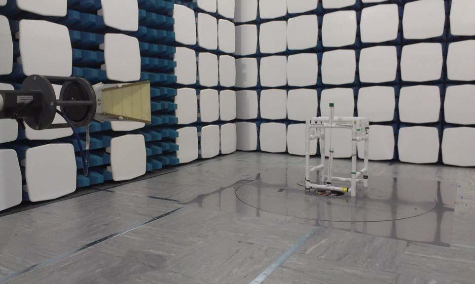
36 Photograph 1 36
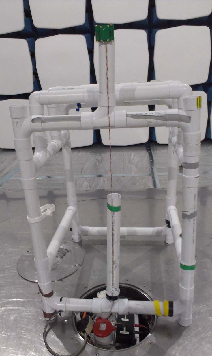
37 Photograph 2 37
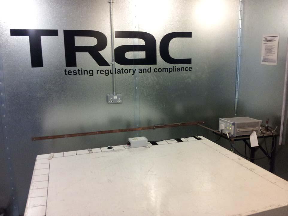
38 Photograph 3 38
39 Appendix G: MPE Calculation OET Bulletin No. 65, Supplement C CFR and & RSS Radio frequency radiation exposure evaluation: mobile devices. For purposes of these requirements mobile devices are defined by the FCC as transmitters designed to be used in other than fixed locations and to generally be used in such a way that a separation distance of at least 20 centimetres is normally maintained between radiating structures and the body of the user or nearby persons. These devices are normally evaluated for exposure potential with relation to the MPE limits. As the 20cm separation specified under FCC rules may not be achievable under normal operation of the EUT, an RF exposure calculation is needed to show the minimum distance required to be less than 1mW/cm 2 power density limit, as required under FCC rules. Prediction of MPE limit at a given distance Equation from page 18 of OET Bulletin 65, Edition S EIRP EIRP re - arranged R 2 4 R S 4 where: S = power density R = distance to the centre of radiation of the antenna EIRP = EUT Maximum power Note: The EIRP measurement was performed using a signal substitution method. Result Prediction Frequency (MHz) Maximum EIRP (mw) Power density limit (S) (mw/cm 2 ) Distance (R) cm required to be less than 1mW/cm cm The FCC limit of 1mW/cm 2 10 W/m 2 the limit as defined in RSS

40
A RADIO TEST REPORT FOR. G4S Monitoring Technologies LTD. OM247 SOLO2 3G 915MHz DOCUMENT NO.TRA WUS4
 A RADIO TEST REPORT FOR G4S Monitoring Technologies LTD ON OM247 SOLO2 3G 915MHz 10-0165-4 DOCUMENT NO.TRA-016455WUS4 TRaC Wireless Test Report : TRA-016455WUS4 Applicant : G4S Monitoring Technologies
Total number of pages : 116
 TRaC Radio Test Report : TRA-016954WUS1 Applicant : Pace Plc Apparatus : PX032ANI Set Top Box Specification(s) : CFR47 Part 15.225 : CFR47 Part 15.247 FCCID :NQ8PX032ANI Purpose of Test : Certification
: M Leach, Principal EMC Engineer.
 EMC Test Report : TTR-002356GUS2 Applicant : Pace plc. Apparatus : RNG210n Authorised by : : M Leach, Principal EMC Engineer. Issue Date : 16 th November 2010 Authorised Copy Number : PDF grepbl.doc Ver:
TEST REPORT FROM RFI GLOBAL SERVICES LTD
 FROM RFI GLOBAL SERVICES LTD Test of: CIBS To: FCC Part 15.247: 2008 Subpart C, RSS-210 Issue 7 June 2007 & RSS-Gen Issue 2 June 2007 Test Report Serial No: RFI/RPT2/RP75103JD05A Supersedes Test Report
FCC CERTIFICATION TEST REPORT
 Report No:DDT-RE120176 Issued Date: 2013/01/05 FCC CERTIFICATION TEST REPORT FOR Applicant : AliMed Inc. Address : 297 High St Dedham Ma 02026 Equipment under Test : Alert transmitter Model No : #712716
Chapter I - Federal Communications Commission Subchapter A - General Part 15 - Radio Frequency Devices Subpart C - Intentional Radiators
 www.nemko.com Report Reference ID 167484-1TRFWL Test specification Title 47 - Telecommunication Chapter I - Federal Communications Commission Subchapter A - General Part 15 - Radio Frequency Devices Subpart
Compliance Engineering Ireland Ltd
 Page 1 of 27 Compliance Engineering Ireland Ltd RAYSTOWN, RATOATH ROAD, ASHBOURNE, CO. MEATH, IRELAND Tel: +353 1 8256722 Fax: +353 1 8256733 Project Number: 10E2475-5 Prepared for: Biancamed Ltd By Compliance
Report on the Radio Testing. For. Tunstall Healthcare (UK) Ltd. Universal Sensor (312) Report no. TRA
 Ltd. Universal Sensor (312) Report no. TRA") Report on the Radio Testing For Tunstall Healthcare (UK) Ltd on Universal Sensor (312) Report no. TRA-031108-45-00 31 st August 2016 RF922 3.0 Report Number: Issue: TRA-031108-45-00 B REPORT ON THE RADIO
Report on the Radio Testing For Tunstall Healthcare (UK) Ltd on Universal Sensor (312) Report no. TRA-031108-45-00 31 st August 2016 RF922 3.0 Report Number: Issue: TRA-031108-45-00 B REPORT ON THE RADIO
DIGITAL OUTSTATION WITH RESPECT TO THE FCC RULES CFR 47, PART 90 INTENTIONAL RADIATOR SPECIFICATION ON BEHALF OF PALMER ENVIRONMENTAL
 TEST REPORT NO: RU1017/4145 COPY NO: 2 ISSUE NO: 1 FCC ID: MJCMD REPORT ON THE CERTIFICATION TESTING OF A PALMER ENVIRONMENTAL Ltd MICROCORR DIGITAL OUTSTATION WITH RESPECT TO THE FCC RULES CFR 47, PART
TRFWL. Autostart Inc Rue Paré Mont-Royal, Québec Canada, H4P 2M2 EZSNAH2503
 Nemko Test Report: 109054-1TRFWL Applicant: Autostart Inc. 5764 Rue Paré Mont-Royal, Québec Canada, H4P 2M2 Apparatus: ASRA 2503 FCC ID: EZSNAH2503 In Accordance With: FCC Part 15 Subpart B, 15.107 and
EMI -- T E S T R E P O R T
 Registration No. DAT-P-207/05 EMI -- T E S T R E P O R T - FCC Part 15.249 - Test Report No. : T33922-00-01HS 18. February 2010 Date of issue Type / Model Name : Keyboard KBRFUSB Product Description :
Table of Contents 1. GENERAL INFORMATION SYSTEM TEST CONFIGURATION CONDUCTED EMISSIONS TEST RADIATED EMISSION TEST...
 Table of Contents 1. GENERAL INFORMATION... 4 1.1 PRODUCT DESCRIPTION FOR EQUIPMENT UNDER TEST... 4 1.2 RELATED SUBMITTAL(S) / GRANT (S)... 7 1.3 TEST METHODOLOGY... 7 1.4 EQUIPMENT MODIFICATIONS... 7
FCC 47 CFR PART 15 SUBPART C INDUSTRY CANADA RSS-210 ISSUE 8 BLUETOOTH LOW ENERGY CERTIFICATION TEST REPORT FOR. 2.4GHz LE MODULE MODEL NUMBER: RN4020
 FCC 47 CFR PART 15 SUBPART C INDUSTRY CANADA RSS-210 ISSUE 8 BLUETOOTH LOW ENERGY CERTIFICATION TEST REPORT FOR 2.4GHz LE MODULE MODEL NUMBER: RN4020 REPORT NUMBER: 14U17191-1 ISSUE DATE: MARCH 21, 2014
FCC CFR47 PART 15 SUBPART C INDUSTRY CANADA RSS-GEN AND RSS-210 CERTIFICATION TEST REPORT FOR BROADCOM BLUETOOTH MODULE MODEL NUMBER: BCM92046MD
 FCC CFR47 PART 15 SUBPART C INDUSTRY CANADA RSS-GEN AND RSS-210 CERTIFICATION TEST REPORT FOR BROADCOM BLUETOOTH MODULE MODEL NUMBER: BCM92046MD IC #: 4324A-BRCM1029 REPORT NUMBER: 07U11199-1C ISSUE DATE:
Medtronic MiniMed TEST REPORT FOR. GST3 Glucose Sensor Transmitter, MMT-7763A. Tested To The Following Standards:
 Medtronic MiniMed TEST REPORT FOR GST3 Glucose Sensor Transmitter, MMT-7763A Tested To The Following Standards: FCC Part 15 Subpart C Sections 15.247 Date of issue: October 31, 2013 This test report bears
TABLE OF CONTENTS 1. GENERAL INFORMATION... 4
 TABLE OF CONTENTS 1. GENERAL INFORMATION... 4 1.1. EUT DESCRIPTION... 4 1.2. TEST STANDARDS AND RESULTS... 5 1.3. FACILITIES AND ACCREDITATIONS... 6 1.3.1. FACILITIES... 6 1.3.2. TEST ENVIRONMENT CONDITIONS...
TEST REPORT. For RFID READER/WRITER. In conformity with. FCC CFR 47 Part15 Subpart C
 TEST REPORT For RFID READER/WRITER In conformity with FCC CFR 47 Part15 Subpart C Model: TR3XM-SD01 / TR3XM-SU01 / TR3XM-SN01 FCC ID: MK4TR3XM-SX01 Test Item: RFID READER/WRITER Report No: RY1203Z12R1
EMI T E S T R E P O R T
 EMI T E S T R E P O R T - FCC Part 15B - Test Report No. : T38935-00-02TK 27. November 2014 Date of issue Type / Model Name : One Touch Select Plus Flex Product Description : Blood glucose meter with Bluetooth
Page 1 of 51 Report No.: T TEST REPORT FCC ID: 2AGJ5WAP-30. In Accordance with: FCC PART 15, SUBPART C : 2015 (Section 15.
 Page 1 of 51 Report No.: T1851663 01 TEST REPORT FCC ID: 2AGJ5WAP-30 Applicant Address : Gonsin Conference Equipment Co., Ltd : No.401-406,Block C, Idea Industry Park, No.41 Fengxiang Road, Shunde, Foshan,
FCC Report for Parts ,
 FCC Report for Parts 15.247, 15.7 Product name Applicant FCC ID : WSN Node : Evalan : 2AK2M-EVAWSN-N15 Test report No. : 1100161 Ver 1.00 Laboratory information Accreditation Telefication is designated
FCC CFR47 PART 15 SUBPART C INDUSTRY CANADA RSS-210 ISSUE 7 CERTIFICATION TEST REPORT FOR g WIRELESS LAN + BLUETOOTH PCI-E MINI CARD
 FCC CFR47 PART 15 SUBPART C INDUSTRY CANADA RSS-210 ISSUE 7 CERTIFICATION TEST REPORT FOR 802.11g WIRELESS LAN + BLUETOOTH PCI-E MINI CARD MODEL NUMBER: BCM94312HMGB REPORT NUMBER: 09U12439-2 ISSUE DATE:
HID GLOBAL CORPORATION
 HID GLOBAL CORPORATION RFID READER, OPERATING ON 125 KHZ AND 13.56 MHZ Model: ERP40C 12 January 2010 Report No.: SL09050401-HID-011_ERP40C (15.225 & RSS-210) (This report supersedes None)) Modifications
EMI T E S T R E P O R T
 EMI T E S T R E P O R T - FCC Part 15.249, RSS210 - Test Report No. : T36940-00-00TK 27. August 2013 Date of issue Type / Model Name : PRA30 Product Description : Radio remote control for Laser detector
Report on the Intermodulation Testing. For. Technology Solutions (UK) Ltd Bluetooth Rugged UHF RFID Reader. Report no.
 Ltd Bluetooth Rugged UHF RFID Reader. Report no.") Report on the Intermodulation Testing For Technology Solutions (UK) Ltd on 1166 Bluetooth Rugged UHF RFID Reader Report no. TR-913-47-1 17 TH - TH June 16 RF915 4. Report Number: Issue: TR-913-47-1 REPORT
Report on the Intermodulation Testing For Technology Solutions (UK) Ltd on 1166 Bluetooth Rugged UHF RFID Reader Report no. TR-913-47-1 17 TH - TH June 16 RF915 4. Report Number: Issue: TR-913-47-1 REPORT
TEST REPORT FROM RADIO FREQUENCY INVESTIGATION LTD.
 TEST REPORT FROM RADIO FREQUENCY INVESTIGATION LTD. Test Of: Wood & Douglas Ltd ST500 Transmitter Test Report Serial No: RFI/EMCB2/RP39403B This Test Report supersedes RFI Test Report No.: RFI/EMCB1/RP39403B
F2 Labs Peters Road Middlefield, Ohio United States of America
 F2 Labs 1674 Peters Road Middlefield, Ohio 4462 United States of America www.f2labs.com CERTIFICATION TEST REPORT Manufacturing Address: Applicant: Product Name: Product Description: Model(s): Beijing
FCC 47 CFR PART 15 SUBPART C INDUSTRY CANADA RSS-210 ISSUE 8 CERTIFICATION TEST REPORT FOR. Dolphin CT50
 FCC 47 CFR PART 15 SUBPART C INDUSTRY CANADA RSS-210 ISSUE 8 CERTIFICATION TEST REPORT FOR Dolphin CT50 MODEL NUMBER: CT50LFN IC ID: 1693B-CT50LFN REPORT NUMBER: 15U20259-E6 ISSUE DATE: JUNE 08, 2015 Prepared
TEST REPORT. Reference No... : WTS16S E FCC ID... : SJ8-UDR777HD. Applicant... : RDI Technology Shenzhen Co., Ltd.
 TEST REPORT Reference No.... : WTS16S0449305E FCC ID... : SJ8-UDR777HD Applicant... : RDI Technology Shenzhen Co., Ltd. Address... : Building C1, Xintang Industrial Park East Baishixia, Fuyong, Baoan,
TRANSMITTER MODEL: KAS-2030M
 Page 1 of 16 FCC PART 15, SUBPART B and C TEST REPORT for TRANSMITTER MODEL: KAS-2030M Prepared for WILDLIFE TECHNOLOGIES 115 WOLCOTT STREET MANCHESTER, NEW HAMPSHIRE 03103 Prepared by: KYLE FUJIMOTO Approved
Electromagnetic Compatibility Test Report DIGITAL INDICATOR. MarCator 1086 R
 Report No.: 31250763.001 Page 1 of 37 - Electromagnetic Compatibility Test Report Prepared in accordance with FCC Part 15C, RSS-210 Issue 8 and ANSI C63.10 On DIGITAL INDICATOR MarCator 1086 R Mahr Federal
TEST REPORT FROM RFI GLOBAL SERVICES LTD
 FROM RFI GLOBAL SERVICES LTD Test Report Serial No: RFI/RPTE2/RP48909JD015A Supersedes Test Report Serial No: RFI/RPTE1/RP48909JD015A This Test Report Is Issued Under The Authority Of Michael Derby, Radio
TEST REPORT. Table of Contents
 Page:2 of 43 Table of Contents 1. DOCUMENT POLICY AND TEST STATEMENT... 4 1.1 DOCUMENT POLICY... 4 1.2 TEST STATEMENT... 4 2. DESCRIPTION OF EUT AND TEST MODE... 4 2.1 GENERAL DESCRIPTION OF EUT... 4 2.2
FCC PART TEST REPORT. Zhejiang Flashforge 3D Technology CO., Ltd
 FCC PART 15.247 TEST REPORT For Zhejiang Flashforge 3D Technology CO., Ltd No. 518, Xianyuan Road, Jinhua, Zhejiang, China FCC ID: 2AKLL-ADVENTURER3 Report Type: Original Report Product Type: 3D PRINTER
FCC AND IC CERTIFICATION TEST REPORT
 Issued Date: Mar. 8, 205 FCC AND IC CERTIFICATION TEST REPORT FOR Applicant : Harman International Industries, Incorporated Address : 8500 Balboa Blvd, Northridge, CA 9329, UNITED STATES Equipment under
HID GLOBAL CORPORATION
 HID GLOBAL CORPORATION RFID READER, OPERATING ON 125 KHZ AND 13.56 MHZ Model: RMP40C, RM40C April 26th 2010 Report No.: SL10040902-HID-006(FCC,IC)-RMP40C (This report supersedes None) Modifications made
7. Transmitter Radiated Spurious Emissions and Conducted Spurious Emission
 7. Transmitter Radiated Spurious Emissions and Conducted Spurious Emission 7.1 Test Setup Refer to the APPENDIX I. 7.2 Limit According to 15.247(d), in any 100 khz bandwidth outside the frequency band
Title: Test on 5.8 GHz Band Outdoor WiFi (802.11b/g) Wireless Base Station
 Wireless Base Station") Page 20 of 51 Pages 7.5. Conducted spurious emission 7.5.1. Requirements: Clause 15.247(d). In any 100 khz bandwidth outside the frequency band in which the spread spectrum or digitally modulated intentional
Page 20 of 51 Pages 7.5. Conducted spurious emission 7.5.1. Requirements: Clause 15.247(d). In any 100 khz bandwidth outside the frequency band in which the spread spectrum or digitally modulated intentional
APPLICATION FOR CERTIFICATION On Behalf of Futaba Corporation Radio Control Model No.:T10CG-2.4G FCC ID:AZPT10CG-24G Brand : Futaba
 FCC ID. AZPT10CG-24G Page 1 of 56 APPLICATION FOR CERTIFICATION On Behalf of Futaba Corporation Radio Control Model No.:T10CG-2.4G FCC ID:AZPT10CG-24G Brand : Futaba Prepared for : Futaba Corporation 1080
TEST REPORT FROM RFI GLOBAL SERVICES LTD
 TEST REPORT FROM RFI GLOBAL SERVICES LTD Test of: Ingenico France, IWL252-01T1535A To: 47CFR15.107, 47CFR15.109 and RSS-GEN Issue 3 December 2010 Test Report Serial No: RFI-EMC-RP82173JD02A V2.0 Version
FCC & RSS-216 (Class II Permissive Change) Wireless Power Transfer Report. for A Acer Incorporated
 Wireless Power Transfer Report. for A Acer Incorporated") Page 1 of 17 FCC 15.209 & RSS-216 (Class II Permissive Change) Wireless Power Transfer Report for A Acer Incorporated 8F., No.88, Sec. 1, Xintai 5th Rd., Xizhi, New Taipei City 22181, Taiwan (R.O.C) Product
Page 1 of 17 FCC 15.209 & RSS-216 (Class II Permissive Change) Wireless Power Transfer Report for A Acer Incorporated 8F., No.88, Sec. 1, Xintai 5th Rd., Xizhi, New Taipei City 22181, Taiwan (R.O.C) Product
Report on the Radio Testing. For. Raspberry Pi (Trading) Ltd. Raspberry Pi 3. Report no. TRA B
 Ltd. Raspberry Pi 3. Report no. TRA B") Report on the Radio Testing For Raspberry Pi (Trading) Ltd on Raspberry Pi 3 Report no. TRA-0273-45-00B 8th February 6 RF95 2.0 Report Number: Issue: TRA-0273-45-00B B REPORT ON THE RADIO TESTING OF A
Report on the Radio Testing For Raspberry Pi (Trading) Ltd on Raspberry Pi 3 Report no. TRA-0273-45-00B 8th February 6 RF95 2.0 Report Number: Issue: TRA-0273-45-00B B REPORT ON THE RADIO TESTING OF A
OUTDOOR SOUND MODULE/TRANSMITTER MODEL: THE BANDIT
 Page 1 of 16 FCC PART 15, SUBPART B and C TEST REPORT for OUTDOOR SOUND MODULE/TRANSMITTER MODEL: THE BANDIT Prepared for MINASKA OUTDOORS 6517 PLATTE AVENUE LINCOLN, NEBRASKA 68507 Prepared by: KYLE FUJIMOTO
EMI T E S T R E P O R T
 EMI T E S T R E P O R T - FCC Part 15.209- Test Report No. : T37170-00-00KG 10. September 2013 Date of issue Type / Model Name : USB Card Reader / MU02016 Product Description : USB Card reader working
FCC PART TEST REPORT. Weccan Industrial Limited
 FCC PART 15.249 TEST REPORT For Weccan Industrial Limited Rm209, 2/F, Building W1-A, No.34 Gaoxin South 4th St Hi-Tech Industrial Park, Nanshan District, Shenzhen China FCC ID: Z3CWECCANDRONE Report Type:
Itron, Inc. TEST REPORT FOR. RF Telemetry Device Model: CCU100. Tested To The Following Standards:
 Itron, Inc. TEST REPORT FOR RF Telemetry Device Model: CCU100 Tested To The Following Standards: FCC Part 15 Subpart C Sections 15.247 and RSS 210 Issue 8 Date of issue: April 25, 2013 This test report
FCC CFR47 PART 15 SUBPART C INDUSTRY CANADA RSS-247 ISSUE 1 BLUETOOTH LOW ENERGY CERTIFICATION TEST REPORT FOR
 FCC CFR47 PART 15 SUBPART C INDUSTRY CANADA RSS-247 ISSUE 1 BLUETOOTH LOW ENERGY CERTIFICATION TEST REPORT FOR WLAN 2X2 MIMO 802.11a/b/g/n/ac with BLUETOOTH MODEL NUMBER: P2180 REPORT NUMBER: 15U21878-E2V1
Revision history. Revision Date of issue Test report No. Description KES-RF-14T0042 Initial
 Page (2 ) of (34) Revision history Revision Date of issue Test report No. Description - 2014.08.25 Initial Page (3 ) of (34) TABLE OF CONTENTS 1. General information... 4 1.1. EUT description... 4 1.2.
TEST REPORT. Report Number: MIN-001 Rev 1.1 Project Number: G Testing performed on the 2102 IPG
 TEST REPORT Report Number: 100511823MIN-001 Rev 1.1 Project Number: G100511823 Testing performed on the 2102 IPG FCC ID: SVHBAROSTIMIPG1 Industry Canada ID: 9464A-IPG210A to 47 CFR Part 95 Subpart I:2013
Measurement of RF Emissions from a Caterpillar Inc. MSS3s RF ID Key Fob
 Measurement of RF Emissions from a Caterpillar Inc. MSS3s RF ID Key Fob For Caterpillar Inc. 330 S.W. Adams Street Peoria, IL 61630 P.O. Number JBL 11260 Date Tested May 11, 2016 Test Personnel Mark Longinotti
TEST REPORT SZEM CR
 No. 1 Workshop, M-10, Middle section, Science & Technology Park, Shenzhen, Guangdong, China 518057 Telephone: +86 (0) 755 2601 2053 Fax: +86 (0) 755 2671 0594 Email: ee.shenzhen@sgs.com Application No.:
EMI -- T E S T R E P O R T
 Registration No. DAT-P-207/05 EMI -- T E S T R E P O R T - FCC Part 15B - Test Report No. : T32619-00-04HU 24. July 2008 Date of issue Type / Model Name : R-PO7470 Product Description : Handheld Reader
FCC CFR47 PART 15 SUBPART C CERTIFICATION TEST REPORT FOR PCMCIA RFID READER CARD MODEL NUMBER: MPR6000 FCC ID: NTTWJMPR6XXX REPORT NUMBER: 04U2954-3
 FCC CFR47 PART 15 SUBPART C CERTIFICATION TEST REPORT FOR PCMCIA RFID READER CARD MODEL NUMBER: MPR6000 FCC ID: NTTWJMPR6XXX REPORT NUMBER: 04U2954-3 ISSUE DATE: NOVEMBER 22, 2004 Prepared for WJ COMUNICATIONS
RF test report AU02+W01
 Customer: Zeppelinstraße 11 82178 Puchheim Tel.: +49 89 5529961-0 Fax: +49 89 5529961-129 RF test report 170761-AU02+W01 The test result refers exclusively to the tested model. This test report may not
FCC 47 CFR PART 15 SUBPART C CERTIFICATION TEST REPORT FOR. Bluetooth Remote Control for Video Set Top Box MODEL NUMBER: IPRC1000 FCC ID: 2ABTE-L3YJC9
 FCC 47 CFR PART 15 SUBPART C CERTIFICATION TEST REPORT FOR Bluetooth Remote Control for Video Set Top Box MODEL NUMBER: IPRC1000 REPORT NUMBER: 15U22448-E1V4 ISSUE DATE: 3/7/2016 Prepared for Verizon Online
PAX Technology Limited
 PAX Technology Limited EFT-POS Terminal January 06, 2013 (This report supersedes NONE) Modifications made to the product : None This Test Report is Issued Under the Authority of: William Long Compliance
FCC ID: 2ALT5-GW6088
 TEST REPORT FCC ID: 2ALT5-GW6088 For GREAT WORLD LTD Electric Heater Model No. : GW-6078TBT, GW-6088TBT, GW-5088C-AMBT, GW-6088TMBT Trade Name : N/A Prepared for : Address : GREAT WORLD LTD 406 Room 1,
FCC TEST REPORT FCC ID: PFNDMS2344UHDW
 Table of Contents FCC Measurement Report 1. Introduction 2. Product Information 3. Description of Tests 4. Test Condition 5. Test Results 5.1 Summary of Test Results 5.2 6 db Bandwidth 5.3 Maximum Peak
CETECOM ICT Services GmbH
 Radio Satellite Communication Untertürkheimer Straße 6 10, D-66117 Saarbrücken, Telephone +49 (0) 681 598-0, Fax +49 (0) 681 598 9075 Test report No.: 1-2272-01-02/10 This test report consists of 43 pages
EMC TEST REPORT RADISYS CORPORATION. Tel: Fax:
 EMC TEST REPORT Report No.: Product: Model No. : FCC2012-8029E GSM Tracker PRIME AT PLT Brand Name: PRIME Applicant: Address: Issued by: Lab Location: RADISYS CORPORATION 601 North Congress Ave Suite 439,
FCC ID: B4OCC264BPA-S
 FCC TEST REPORT FCC ID: B4OCC264BPA-S Product : Bluetooth LE Module Model Name : CC264BPA-S, CC265BPA-S, CC26xBPA Brand : GT-tronics Report No. : PTC801181160622E-FC01 Prepared for GT-tronics HK Ltd Unit
FCC PART & IC RSS GHz FHSS TEST REPORT
 FCC PART 15.247 & IC RSS-247 2.4 GHz FHSS TEST REPORT 849 NW State Road 45 Newberry, FL 32669 USA Ph.: 888.472.2424 or 352.472.5500 Fax: 352.472.2030 Email: info@timcoengr.com Website: www.timcoengr.com
TEST REPORT. Shenzhen, PRC.
 TEST REPORT Reference No.... : WTS16S0449309E FCC ID... : SJ8-UDRC57 Applicant... : RDI Technology Shenzhen Co., Ltd. Address... : Building C1, Xintang Industrial Park East Baishixia, Fuyong, Baoan, Shenzhen,
REPORT REVISION HISTORY...
 Reference No.: WTS17S0579239E Page 2 of 39 2 Contents Page 1 COVER PAGE... 1 2 CONTENTS... 2 3 REPORT REVISION HISTORY... 3 4 GENERAL INFORMATION... 4 4.1 GENERAL DESCRIPTION OF E.U.T.... 4 4.2 DETAILS
FCC PART 15C IC RSS-210, ISSUE 7, JUNE 2007 TEST AND MEASUREMENT REPORT. SunPower Corporation
 FCC PART 15C IC RSS-210, ISSUE 7, JUNE 2007 TEST AND MEASUREMENT REPORT For SunPower Corporation 1414 Harbour Way South, Richmond, CA 94804, USA FCC ID: YAW110884 IC: 8917A-110884 Report Type: Original
Electromagnetic Compatibility Test Report. VERASENSE for Zimmer Biomet Persona
 Report No.: 31653637.001 Page 1 of 31 Electromagnetic Compatibility Test Report Tested to FCC Part 15C & RSS-210 Issue 9 On VERASENSE for Zimmer Biomet Persona Model: CR C-D/3-9 LEFT, ZBH- PSNCRCD39-L,
TEST REPORT. Issued for: ShenZhen MYGT Co.,LTD D3 Tongfuyu Industrial Area Community of Shajing Town, Baoan, Shenzhen, China.
 TEST REPORT FCC ID: 2AMKEMY-C11 Product: Wireless Gamepad Model No.: MY-C11 Additional Model No.: TKGC01 Trade Mark: N/A Issued Date: Oct. 16, 2017 Issued for: ShenZhen MYGT Co.,LTD D3 Tongfuyu Industrial
TEST REPORT. Issued for: RUIMA INTERNATIONAL(HK)INDUSTRIAL CO.,LIMITED NO.19 Ruixiang Road, Xinhua Industrial Zone, Huadu District, Guangzhou China
INDUSTRIAL CO.,LIMITED NO.19 Ruixiang Road, Xinhua Industrial Zone, Huadu District, Guangzhou China") TEST REPORT FCC ID: 2AHSJRM-626B Product: Boombox Speaker Model No.: RM-626 Additional Model: STREET HOPPER 6, CANNON 6 Trade Mark: RUIMA Issued Date: Aug. 04, 2016 Issued for: RUIMA INTERNATIONAL(HK)INDUSTRIAL
TEST REPORT FCC ID: 2AHSJRM-626B Product: Boombox Speaker Model No.: RM-626 Additional Model: STREET HOPPER 6, CANNON 6 Trade Mark: RUIMA Issued Date: Aug. 04, 2016 Issued for: RUIMA INTERNATIONAL(HK)INDUSTRIAL
DATES OF TESTS: From 03/10/2014 to 20/10/2014 and 25/02/2015. Open area test site in Aunainville (28) - FRANCE. Page 2 out of 54
 - FRANCE. Page 2 out of 54") TEST CERTIFICATION FOR: FCC Certification NAME OF THE EQUIPMENT UNDER TEST: Serial number: Wireless conference access point Type: CONFIDEA WCAP G3 1440077150000C1 Reference / model (P/N): 71.98.0033 V
TEST CERTIFICATION FOR: FCC Certification NAME OF THE EQUIPMENT UNDER TEST: Serial number: Wireless conference access point Type: CONFIDEA WCAP G3 1440077150000C1 Reference / model (P/N): 71.98.0033 V
EMC Test Report. Tested by: Jeremy O. Pickens, Senior EMC Engineer. Reviewed by: David Schramm, EMC/RF/SAR/HAC Manager
 Page: 1 of 24 EMC Test Report Project Number: 4104971 Report Number: 4104971EMC01 Revision Level: 0 Client: Tier One, Inc. Equipment Under Test: GEN4 Glock Sensor Model Number: BA10232 FCC ID: 2AJ3810232
Test Report. FCC Part 15, Subpart C, Section Industry Canada RSS-210, Issue 7
 Test Report FCC Part 5, Subpart C, Section 5.247 Industry Canada RSS-, Issue 7 Report Number: CWD67-Cert Model: CWD67 Date: March 3, 0 Prepared by: Grace Lin Date: Mar. 3, 0 Grace Lin, Sr. Compliance Engineer
Quality Auditing Institute # Schoolhouse Street, Coquitlam, BC, V3K 4X9, Canada. ISO Accreditation:
 CANADA: 16-211 Schoolhouse Street Coquitlam, British Columbia Canada V3K 4X9 ELECTROMAGNETIC COMPATIBILITY TEST REPORT TO CFR 47 FCC Part 15, Subpart C, Section 15.225 Industry Canada RSS 210, Issue 8
Report On. FCC and Industry Canada Testing of the Inmarsat Global Ltd IsatPhone Pro GMR2+ Satellite Phone COMMERCIAL-IN-CONFIDENCE
 Report On FCC and Industry Canada Testing of the Inmarsat Global Ltd IsatPhone Pro GMR2+ Satellite Phone FCC ID: YCTISATPHONE IC ID: 8944A-ISATPHONE Document 75909459 Report 07 Issue 1 June 2010 TUV Product
RADIO TEST REPORT. According to. 47 CFR FCC Part 15 Subpart C
 RADIO TEST REPORT According to 47 CFR FCC Part 15 Subpart C 15.247 Equipment Model Name Frequency Range Applicant FCC ID : Cable Modem : TC8305C PKE1331BP-D49 (US-Dory-RoHS) : 2400 MHz 2483.5 MHz : Askey
Test Report: 5R Champlain Street Dieppe, New Brunswick Canada E1A 1P6. Model Number: Verification
 Test Report: 5R46150.1 Applicant: Equipment Under Test: Model Number: In Accordance With: Tested By: Nanoptix Inc. 699 Champlain Street Dieppe, New Brunswick E1A 1P6 Spill Proof Cuts SPC FCC 47 CFR Part
Test Report. Bluetooth Transceiver in UPCS Base Station. Panasonic Corporation of North America
 Report No. 318949-3 Test Report Product Name and address of the applicant Bluetooth Transceiver in UPCS Base Station Panasonic Corporation of North America Name and address of the manufacturer Model Panasonic
SGS United Kingdom Ltd. International Electrical Approvals. Electromagnetic Compatibility. RF Card Entry System. PAC International Ltd.
 South Industrial Estate Bowburn Co. Durham DH6 5AD United Kingdom Tel: +44 (0) 191 377 2000 Fax: +44 (0) 191 377 2020 email: sgsiea@sgs.com SGS United Kingdom Ltd. International Electrical Approvals Electromagnetic
ITL Page 2 of 71 Report No.:
 ITL Page 1 of 71 Report No.: 12092752 TEST REPORT Applicant: Address of Applicant: Harman International Industries, Incorporated 8500 Balboa Blvd, Northridge, CA 91329, United States Manufacturer: Address
XBee Series 2 OEM RF Module Model No.: XBEE2 FCC ID: OUR-XBEE2. Applicant: MaxStream, Inc. 355 South 520 West Suite 180 Lindon, UT 84042
 XBee Series 2 OEM RF Module Model No.: XBEE2 Applicant: MaxStream, Inc. 355 South 520 West Suite 180 Lindon, UT 84042 In Accordance With Federal Communications Commission (FCC) Part 15, Subpart C, Section
RF test report AU01+W02
 Customer: Kehlbergstrasse 109 8054 Graz Austria Tel.: +43 664 415 6260 RF test report 170186-AU01+W02 The test result refers exclusively to the tested model. This test report may not be copied or published
Jul. 16, Jun. 04, Shenzhen. Tel:(86-755)
") Test Report FCC ID.: MTi160413E004 Date of issue: Jul. 16, 2016 Sample Description: Wireless POS Terminal Model(s): G3 Applicant: Shenzhen Xinguodu Technology Co., Ltd. Address: 17/A, Jinsong Building
Test Report FCC ID.: MTi160413E004 Date of issue: Jul. 16, 2016 Sample Description: Wireless POS Terminal Model(s): G3 Applicant: Shenzhen Xinguodu Technology Co., Ltd. Address: 17/A, Jinsong Building
FCC Test Report. Report No.: PTCDQ FC01
 Page 1 of 63 FCC Test Report Report No.: PTCDQ04170450501-FC01 FCC ID : 2AL2XW801 APPLICATION PURPOSE : Original Equipment PRODUCT DESIGNATION : WIFI DoorBell BRAND NAME : EASTIC MODEL NAME : W801, W802,
FCC & IC Certification. Test Report. FCC & Industry Canada Certification. Test Report. for Hetronic USA FCC ID: LW9-CS434TXN IC ID: 2219A-CS434TXN
 FCC & IC Certification Test Report FCC & Industry Canada Certification Test Report for Hetronic USA March 3, 2005 Prepared for: Hetronic USA 4300 Highline Blvd Building 4 Oklahoma City, OK 73108 Prepared
TEST REPORT FCC ID: 2ADMF-HC06. : bluetooth module keyes HC-06, keyes hc-05, FUNDUINO HC-06, FUNDUINO hc-05
 Shenzhen Certification Technology Service Co., Ltd. 2F, Building B, East Area of Nanchang Second Industrial Zone, Gushu 2 nd Road, Bao'an District, Shenzhen 518126, P.R. China TEST REPORT FCC ID: 2ADMF-HC06
EMI -- T E S T R E P O R T
 EMI -- T E S T R E P O R T Test Report No. : T31400-01-00HU 26. February 2007 Date of issue Type / Model Name : R-IN1300MC Product Description : Long Range Industrial RFID High Frequency Reader Applicant
FCC CFR47 PART 15 SUBPART C INDUSTRY CANADA RSS-210 ISSUE 8 CERTIFICATION TEST REPORT FOR
 FCC CFR47 PART 15 SUBPART C INDUSTRY CANADA RSS-210 ISSUE 8 CERTIFICATION TEST REPORT FOR The Apple ipad is a tablet device with multimedia functions (music, application support, and video), 802.11a/b/g/n
Tested To The. and. Report. We strive to TESTING
 Celadon Inc. TEST REPORT FOR Tessonics RF Remote, FGSK18 TES 01 Tested To The Following Standards: FCCC Part 15 Subpart C Sections 15.249 and RSS 210 Version 7 Report No.: 90470 21 Date of issue: June
UNIDEN AMERICA CORPORATION 4700 AMON CARTER BLVD. FORT WORTH TEXAS UNITED STATES
 849 NW STATE ROAD 45 NEWBERRY, FL 32669 USA PH: 888.472.2424 OR 352.472.5500 FAX: 352.472.2030 EMAIL: INFO@TIMCOENGR.COM HTTP://WWW.TIMCOENGR.COM TEST REPORT PER FCC Part 15, Subparts B, C, and D IC RSS-213
RF test report AU01+Z04
 Customer: Lilienthalstraße 3 82178 Puchheim Tel.: +49 89 5529961-13 Fax: +49 89 5529961-29 RF test report 170509-AU01+Z04 The test result refers exclusively to the tested model. This test report may not
Test Report Version. Test Report No. Date Description. DRTFCC Sep. 17, 2014 Initial issue. DEMC Report No.
 FCCID: 2AALG-NWP-F110 Test Report Version Test Report No. Date Description DRTFCC1409-1176 Sep. 17, 2014 Initial issue Page2 / 33 FCCID: 2AALG-NWP-F110 Table of Contents 1. GENERAL INFORMATION... 4 2.
Test Report. ASSA ABLOY Hospitality AS Anolitveien 1-3, 1400 Ski, Norway. ASSA ABLOY Hospitality AS Anolitveien 1-3, 1400 Ski, Norway
 Report No. 284966- Test Report Product Name and address of the applicant Name and address of the manufacturer Model Rating Trademark RFID Transceiver Module ASSA ABLOY Hospitality AS Anolitveien -3, 400
Version TEST REPORT NO. DATE DESCRIPTION
 Version NO. DATE DESCRIPTION HCTR1302FR13 February 14, 2013 - First Approval Report - Additional Model Name Page 2 of 25 Table of Contents 1. GENERAL INFORMATION... 4 2. EUT DESCRIPTION... 4 3. TEST METHODOLOGY...
Date: ESPOO Page: 1 ( 10) Appendices - Transceiver. SATELLINE-EASy Pro 35W SATEL-TA18 SATEL Oy, Finland
 Appendices - Transceiver. SATELLINE-EASy Pro 35W SATEL-TA18 SATEL Oy, Finland") Version R3.03 09092003 TEST REPORT Date: ESPOO 05.10.2010 Page: 1 ( 10) Appendices - Number: 157439 No. 1 / 1 Date of handing in: 17.09.2010 Tested by: Timo Hietala, Test Engineer Reviewed by: Timo Leismala,
Version R3.03 09092003 TEST REPORT Date: ESPOO 05.10.2010 Page: 1 ( 10) Appendices - Number: 157439 No. 1 / 1 Date of handing in: 17.09.2010 Tested by: Timo Hietala, Test Engineer Reviewed by: Timo Leismala,
Page 1 of 20 No.: HM TEST REPORT FCC PART 15 SUBPART C CERTIFICATION REPORT FOR LOW POWER TRANSMITTER. TEST REPORT No.
 Page 1 of 20 FCC PART 15 SUBPART C CERTIFICATION REPORT FOR LOW POWER TRANSMITTER Equipment Under Test [EUT]: Model Number: Applicant: FCC ID : Radio Controlled Tank FH002 Zhongshan Fu Hai Electronics
Certification Test Report
 Certification Test Report FCC ID: Z9O-92053000 IC: 10060A-92053000 FCC Rule Part: 15.209 ISED Canada Radio Standards Specification: RSS-210 Report Number: BO72126038.101 Manufacturer: Ecolab Inc. Model(s):
FCC Test Report. Report No.: AGC FE02 CLIENT : INNOVATIVE CONCEPTS AND DESIGN LLC. Attestation of Global Compliance (Shenzhen) Co., Ltd.
 Co., Ltd.") Page 1 of 43 FCC Test Report Report No.: AGC03588150607FE02 FCC ID : 2AE6GUHF 6000HHM APPLICATION PURPOSE : ORIGINAL EQUIPMENT PRODUCT DESIGNATION : Wireless Microphone BRAND NAME : Gemini MODEL NAME :
Page 1 of 43 FCC Test Report Report No.: AGC03588150607FE02 FCC ID : 2AE6GUHF 6000HHM APPLICATION PURPOSE : ORIGINAL EQUIPMENT PRODUCT DESIGNATION : Wireless Microphone BRAND NAME : Gemini MODEL NAME :
G.S.D. S.r.l. Via Marmiceto, Pisa (loc. Ospedaletto) Italy MARKING. Test Report n. FCC CAEN RFID S.r.l Viareggio (LU) Italy
 Italy MARKING. Test Report n. FCC CAEN RFID S.r.l Viareggio (LU) Italy") MARKING Laboratories ELECTROMAGNETIC COMPATIBILITY ELECTRICAL SAFETY LASER SPECTROSCOPY ENVIRONMENTAL PHYSICS G.S.D. Srl PISA - Italy Test Report n. FCC-17337 Manufacturer Address CAEN RFID S.r.l. Test
MARKING Laboratories ELECTROMAGNETIC COMPATIBILITY ELECTRICAL SAFETY LASER SPECTROSCOPY ENVIRONMENTAL PHYSICS G.S.D. Srl PISA - Italy Test Report n. FCC-17337 Manufacturer Address CAEN RFID S.r.l. Test
2310 to 2390 MHz, 3m distance MCS8 (MIMO) to 2500 MHz Restricted band MCS8 (MIMO)
 to 2500 MHz Restricted band MCS8 (MIMO)") 2310 to 2390 MHz, 3m distance MCS8 (MIMO) Lower band edge, Average (Low Channel) Lower band edge, Peak (Low Channel) 2483.5 to 2500 MHz Restricted band MCS8 (MIMO) Upper band edge, Peak (High Channel)
2310 to 2390 MHz, 3m distance MCS8 (MIMO) Lower band edge, Average (Low Channel) Lower band edge, Peak (Low Channel) 2483.5 to 2500 MHz Restricted band MCS8 (MIMO) Upper band edge, Peak (High Channel)
RADIO REPORT FOR CERTIFICATION 47 CFR PART 15 SUBPART C (SECTION )
") Page 1 of 39 EMC Technologies Pty. Ltd. ABN 82 057 105 549 Melbourne 176 Harrick Road Keilor Park, Vic 3042 Tel: +61 3 9365 1000 Sydney Unit 3/87 Station Road Seven Hills, NSW 2147 Tel: +61 2 9624 2777
Page 1 of 39 EMC Technologies Pty. Ltd. ABN 82 057 105 549 Melbourne 176 Harrick Road Keilor Park, Vic 3042 Tel: +61 3 9365 1000 Sydney Unit 3/87 Station Road Seven Hills, NSW 2147 Tel: +61 2 9624 2777
FCC Test Report. Wayne Hsu / Assistant Manager
 FCC Test Report Equipment : Wireless Pedometer/Tracker Brand Name : ASE Group Model No. : M903 Standard : 47 CFR FCC Part 15.247 Operating Band : 2400 MHz 2483.5 MHz FCC Classification : DTS Applicant
RF Emissions Test Report To Determine Compliance With: FCC, Part 15 Rules and Regulations
 RF Emissions Test Report To Determine Compliance With: FCC, Part 15 Rules and Regulations Model numbers: HT130022 Rev. B. December 17, 2002 Manufacturer: HQ, Inc. 210 9th Steet Drive Palmetto, FL 34221