03001 R.M. Young Wind Sentry Set R.M. Young Wind Sentry Anemometer R.M. Young Wind Sentry Vane Revision: 8/07
|
|
|
- Eustace Phillips
- 6 years ago
- Views:
Transcription
1 03001 R.M. Young Wind Sentry Set R.M. Young Wind Sentry Anemometer R.M. Young Wind Sentry Vane Revision: 8/07 Copyright Campbell Scientific, Inc.
2 Warranty and Assistance The R.M. YOUNG WIND SENTRY SET, R.M. YOUNG WIND SENTRY ANEMOMETER, AND R.M. YOUNG WIND SENTRY VANE are warranted by CAMPBELL SCIENTIFIC, INC. to be free from defects in materials and workmanship under normal use and service for twelve (12) months from date of shipment unless specified otherwise. Batteries have no warranty. CAMPBELL SCIENTIFIC, INC.'s obligation under this warranty is limited to repairing or replacing (at CAMPBELL SCIENTIFIC, INC.'s option) defective products. The customer shall assume all costs of removing, reinstalling, and shipping defective products to CAMPBELL SCIENTIFIC, INC. CAMPBELL SCIENTIFIC, INC. will return such products by surface carrier prepaid. This warranty shall not apply to any CAMPBELL SCIENTIFIC, INC. products which have been subjected to modification, misuse, neglect, accidents of nature, or shipping damage. This warranty is in lieu of all other warranties, expressed or implied, including warranties of merchantability or fitness for a particular purpose. CAMPBELL SCIENTIFIC, INC. is not liable for special, indirect, incidental, or consequential damages. Products may not be returned without prior authorization. The following contact information is for US and International customers residing in countries served by Campbell Scientific, Inc. directly. Affiliate companies handle repairs for customers within their territories. Please visit to determine which Campbell Scientific company serves your country. To obtain a Returned Materials Authorization (RMA), contact CAMPBELL SCIENTIFIC, INC., phone (435) After an applications engineer determines the nature of the problem, an RMA number will be issued. Please write this number clearly on the outside of the shipping container. CAMPBELL SCIENTIFIC's shipping address is: CAMPBELL SCIENTIFIC, INC. RMA# 815 West 1800 North Logan, Utah CAMPBELL SCIENTIFIC, INC. does not accept collect calls.
3 R.M. Young Wind Sentry Table of Contents PDF viewers note: These page numbers refer to the printed version of this document. Use the Adobe Acrobat bookmarks tab for links to specific sections. 1. Introduction Specifications Installation Siting Assembly and Mounting Wind Sentry Set Anemometer Vane Wiring Example Programs Wind Speed Wind Direction Wind Vector Processing Instruction Example Programs CR1000 Example Program CR10X Example Program Long Lead Lengths Sensor Maintenance Troubleshooting Wind Direction Wind Speed References...13 i
4 R.M. Young Wind Sentry Table of Contents Appendices A. Wind Direction Sensor Orientation... A-1 A.1 Determining True North and Sensor Orientation... A-1 B. Wind Direction Measurement Theory... B-1 B.1 AC Half Bridge (P5) and BRHalf Instructions... B-1 B.2 EX-DEL-SE (P4) Instruction... B-1 Figures Tables Mounted to CM200 Series Crossarm with CM Mounted to 019ALU or CM200 Series Crossarm with PN Anemometer Mounted to CM200 Series Crossarm with CM Mounted to CM100 Series Tripod Mast with CM A-1. Magnetic Declination for the Contiguous United States... A-2 A-2. Declination Angles East of True North are Subtracted from 0 to Get True North... A-2 A-3. Declination Angles West of True North are Added to 0 to Get True North... A-3 B /03301 Potentiometer in a Half Bridge Circuit... B Recommended Lead Lengths Connections to Campbell Scientific Dataloggers Wind Speed Multiplier Parameters for Wind Direction Wiring for Example Programs... 9 ii
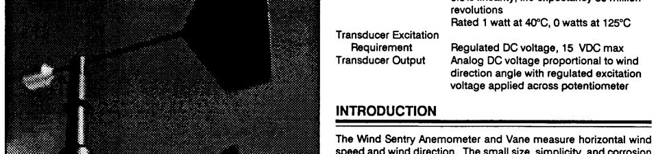
5 R.M. Young Wind Sentry 1. Introduction The Wind Sentry Set is used to measure horizontal wind speed and direction. Wind speed is measured with a three cup anemometer. Rotation of the cup wheel produces an AC sine wave voltage with frequency proportional to wind speed. Vane position is transmitted by a 10K ohm potentiometer. With a precision excitation voltage applied, the output voltage is proportional to wind direction. The Anemometer and Vane can be ordered as separate sensors, which are also covered in this manual. The R.M. Young Instruction Manual includes additional information on the operating principles, installation and maintenance of the sensor. Lead length for the Wind Sentry is specified when the sensor is ordered. Table 1-1 gives the recommended lead length for mounting the sensor at the top of the tripod/tower with a 019ALU or CM200 series crossarm. TABLE 1-1. Recommended Lead Lengths CM6 CM10 CM110 CM115 CM120 UT10 UT20 UT The Wind Sentry ships with: (1) Wind Sentry including Anemometer Vane crossarm band clamp (P/N 4919) (1) 10" x 3/4" unthreaded aluminium pipe (P/N 6332) (1) Allen wrench (P/N 5201) The Anemometer ships with: (1) Anemometer (1) 10" x 3/4" threaded galvanized pipe (P/N 12243) (1) Allen wrench (P/N 5201) 1
6 R.M. Young Wind Sentry 2. Specifications The Vane ships with: (1) Vane (1) 10 x 3/4 threaded galvanized pipe (P/N 12243) (1) Allen wrench (P/N 5201) Wind Speed (Anemometer) Specifications Range: 0 to 50 m s-1 (112 mph), gust survival 60 m s-1 (134 mph) Sensor: 12 cm diameter cup wheel assembly, 40 mm diameter hemispherical cups Accuracy: ±0.5 m s-1 (1.1 mph) Turning Factor: 75 cm (2.5 ft) Distance Constant (63% recovery): 2.3 m (7.5 ft) Threshold: 0.5 m s-1 (1.1 mph) Transducer: Transducer Output: Output Frequency: Cup Wheel Diameter: 12 cm (4.7 in) Weight: 113 g (4 oz) Stationary coil, 1350 ohm nominal resistance AC sine wave signal induced by rotating magnet on cup wheel shaft 100 mv peak-to-peak at 60 rpm; 6 V peak-to-peak at 3600 rpm 1 cycle per cup wheel revolution; 0.75 m s-1 per Hz Wind Direction (Vane) Specifications Range: 360 mechanical, 355 electrical (5 open) Sensor: Balanced vane, 16 cm turning radius Accuracy: ±5 Damping Ratio: 0.2 Delay Distance (50% recovery): 0.5 m (1.6 ft) Threshold: 0.8 m s-1 (1.8 mph) at 10 displacement 1.8 m s-1 (4 mph) at 5 displacement Transducer: Precision conductive plastic potentiometer; 10 K ohm resistance; 0.5% linearity; life expectancy 20 million revolutions. Rated 1 watt at 40 C, 0 watts at 125 C. Transducer Output: Analog dc voltage proportional to wind direction angle with regulated excitation voltage supplied by the datalogger Vane Length: 22 cm (8.7 in) Vane Weight: 170 g (6 oz) Wind Sentry Assembly Specifications Operating Temperature: -50 to +50 C assuming non-riming conditions Overall Height: 32 cm (12.6 in) Crossarm Length: 40 cm (15.7 in) between instruments (center-tocenter) Mounting Diameter: 26.7 mm (1.05 in), mounts on standard 3/4 in. pipe 2
7 R.M. Young Wind Sentry NOTE The black outer jacket of the cable is Santoprene rubber. This compound was chosen for its resistance to temperature extremes, moisture, and UV degradation. However, this jacket will support combustion in air. It is rated as slow burning when tested according to U.L. 94 H.B. and will pass FMVSS302. Local fire codes may preclude its use inside buildings. 3. Installation 3.1 Siting Locate wind sensors away from obstructions (e.g. trees and building). As a general rule of thumb there should be a horizontal distance of at least ten times the height of the obstruction between the windset and the obstruction. If it is necessary to mount the sensors on the roof of a building, the height of the sensors above the roof, should be at least 1.5 times the height of the building. See Section 9 for a list of references that discuss siting wind speed and direction sensors. 3.2 Assembly and Mounting Tools Required: Wind Sentry Set 5/64 Allen wrench Allen wrench provided with sensor 1/2 open end wrench compass and declination angle for the site (see Appendix A) small screw driver provided with datalogger UV resistant cable ties small pair of diagonal-cutting pliers 6-10 torpedo level Install the cupwheel to the anemometer shaft using the Allen wrench provided with the sensor. The mounts to a standard 0.75 IPS schedule 40 pipe (1.05 O.D.). A 12 long mounting pipe ships with the for attaching the sensor to a 019ALU or CM200 series crossarm with the CM220 or PN 1049 (Figures 3-1 and 3-2). The can also be mounted at the top of a CM6/CM10 tripod mast, or to a CM110 series tripod with the CM216 as shown in Figure 3-4. Mount the 019ALU or CM200 series crossarm to the tripod or tower. Orient the crossarm North-South, with the 3/4 Nu-Rail or CM220 on the North end. Appendix A contains detailed information on determining true north using a compass and the magnetic declination for the site. Secure the mounting pipe to the 019ALU or CM220. Place the on the pipe, and orient the sensor crossarm North-South with the vane to the North. Tighten the mounting post band clamp. Final sensor orientation is done after 3


8 R.M. Young Wind Sentry the datalogger has been programmed to measure wind direction as described in Appendix A. Route the sensor cable along the underside of the crossarm to the tower/tripod mast, and to the instrument enclosure. Secure the sensor cable to the crossarm and mast using cable ties. CM220 CM200 Series Crossarm FIGURE Mounted to CM200 Series Crossarm with CM220 PN 1049 Nu-Rail CM200 Series Crossarm FIGURE Mounted to 019ALU or CM200 Series Crossarm with PN


9 R.M. Young Wind Sentry CM220 CM200 Series Crossarm FIGURE Anemometer Mounted to CM200 Series Crossarm with CM220 CM216 FIGURE Mounted to CM100 Series Tripod Mast with CM216 5
10 R.M. Young Wind Sentry Anemometer Install the cupwheel to the anemometer shaft using the Allen wrench provided with the sensor. The mounts to a threaded 0.75 IPS schedule 40 pipe (1.05 O.D.). A 10 long mounting pipe ships with the for attaching the sensor to a 019ALU or CM200 series crossarm with CM220 (Figures 3-3) or PN The can also be mounted at the top of a CM6/CM10 tripod mast, or to a CM110 series tripod with the CM216. Mount the 019ALU or CM200 series crossarm to the tripod or tower. Screw the mounting pipe into the base of the 03101, and attach the sensor / mounting pipe to the crossarm. Route the sensor cable along the underside of the crossarm to the tower/tripod mast, and to the instrument enclosure. Secure the sensor cable to the crossarm and mast using cable ties Vane The Vane is typically ordered as a replacement vane for the Wind Sentry Set, and includes the bracket for attaching it to the crossarm. PN 4913 pipe mount (not included with the sensor) can be used to attach the to a 019ALU or CM200 series crossarm (with the CM220 or PN 1049), and the mounting pipe that ships with the sensor. 4. Wiring Connections to Campbell Scientific dataloggers are given in Table 4-1. When Short Cut for Windows software is used to create the datalogger program, the sensor should be wired to the channels shown on the wiring diagram created by Short Cut. Color TABLE 4-1. Connections to Campbell Scientific Dataloggers Description CR800 CR5000 CR3000 CR1000 CR510 CR500 CR10(X) CR21X CR7 CR23X CR200 Black Wind Spd. Signal Pulse Pulse Pulse P_LL White Wind Spd. Reference G Clear Wind Spd. Shield G Red Wind Dir. Signal SE Analog SE Analog SE Analog SE Analog Black Wind Dir. Excitation Excitation Excitation Excitation Excitation White Wind Dir. Reference AG Clear Wind Dir. Shield G 6
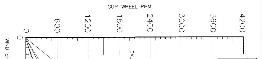
11 R.M. Young Wind Sentry Wind Speed Wind Direction 5. Example Programs 5.1 Wind Speed This section is for users who write their own programs. A datalogger program to measure this sensor can be created using Campbell Scientifics Short Cut Program Builder software. You do not need to read this section to use Short Cut. Wind speed is measured with the Pulse Count instruction, and with the low level AC configuration. For dataloggers programmed with Edlog, specify configuration code 21 to output frequency in Hertz. The expression for wind speed (U) is: U = MX + B where M = multiplier X = number of pulses per second (Hertz) B = offset Table 5-1 lists the multipliers (M) and offsets (Off) to obtain meters/second or miles/hour when the Pulse Count instruction is configured to output the result in Hz. TABLE 5-1. Wind Speed Multiplier (With Configuration Code 21*) Model Meters/Second Miles/Hour / M = Off = 0.2 M = Off = 0.4 *When configuration code 11 is used, the multiplier above is divided by the execution interval in seconds. 7
12 R.M. Young Wind Sentry 5.2 Wind Direction The wind vane is coupled to a 10K potentiometer, which has a 5 degree electrical dead band between 355 and 360 degrees. The EX-DEL_SE measurement instruction (P4) is used for dataloggers that are programmed with Edlog (e.g. CR10X, CR23X) and the CR200. The multiplier to convert the measurement result (mv) to degrees is 355 deg/excitation mv. The BRHalf measurement instruction is used for dataloggers that are programmed with CRBasic (e.g. CR1000, CR3000). The multiplier to convert the measurement result (mv/excitation mv) to degrees is 355. Excitation voltages, range codes, and multipliers for CSI dataloggers are listed in Table 5-2. Appendix B has additional information on the P4 and BRHalf measurement instructions. Measurement Range Excitation Voltage TABLE 5-2. Parameters for Wind Direction CR10(X) CR510 CR mv, slow CR7 21X CR23X 5000 mv, slow/60 Hz CR800 CR mv, 60 Hz, reverse excitation CR5000 CR mv, 60 Hz, reverse excitation 2500 mv 5000 mv 2500 mv 5000 mv Multiplier Offset Wind Vector Processing Instruction 5.4 Example Programs The Wind Vector output instruction is used to process and store mean wind speed, unit vector mean wind direction, and Standard Deviation of the wind direction (optional) from the measured wind speed and direction values. The following programs measure the every 5 seconds, and store mean wind speed, unit vector mean direction, and standard deviation of the direction every 60 minutes. Wiring for the examples is given in Table
13 R.M. Young Wind Sentry TABLE 5-3. Wiring for Example Programs Color Description CR1000 CR10X Black Wind Spd. Signal P1 P1 White Wind Spd. Reference G Clear Wind Spd. Shield G Red Wind Dir. Signal SE 1 SE 1 Black Wind Dir. Excitation EX 1 E1 White Wind Dir. Reference AG Clear Wind Dir. Shield G CR1000 Example Program 'CR1000 'Declare Variables and Units Public Batt_Volt Public WS_ms Public WindDir Units Batt_Volt=Volts Units WS_ms=meters/second Units WindDir=Degrees 'Define Data Tables DataTable(Table1,True,-1) DataInterval(0,60,Min,10) WindVector (1,WS_ms,WindDir,FP2,False,0,0,0) FieldNames("WS_ms_S_WVT,WindDir_D1_WVT,WindDir_SD1_WVT") EndTable 'Main Program BeginProg Scan(5,Sec,1,0) 'Default Datalogger Battery Voltage measurement Batt_Volt: Battery(Batt_Volt) '03001 or RM Young Wind Sentry Wind Speed Sensor measurement - WS_ms: PulseCount(WS_ms,1,1,1,1,0.75,0.2) If WS_ms<0.21 Then WS_ms=0 '03001 or RM Young Wind Sentry Wind Direction Sensor measurement - WindDir: BrHalf(WindDir,1,mV2500,1,1,1,2500,True,0,_60Hz,355,0) 'Use mv5000 range and 5000 mv excitation for CR3000 and CR5000 dataloggers. If WindDir>=360 OR WindDir<0 Then WindDir=0 9
14 R.M. Young Wind Sentry 'Call Data Tables and Store Data CallTable(Table1) NextScan EndProg CR10X Example Program ;{CR10X} *Table 1 Program 01: Execution Interval (seconds) 1: Batt Voltage (P10) 1: 1 Loc [ Batt_Volt ] ;03001 or RM Young Wind Sentry Wind Speed Sensor measurement - WS_ms: 2: Pulse (P3) 1: 1 Reps 2: 1 Pulse Channel 1 3: 21 Low Level AC, Output Hz 4: 2 Loc [ WS_ms ] 5: 0.75 Multiplier 6: 0.2 Offset 3: If (X<=>F) (P89) 1: 2 X Loc [ WS_ms ] 2: 4 < 3: 0.21 F 4: 30 Then Do 4: Z=F x 10^n (P30) 1: 0 F 2: 0 n, Exponent of 10 3: 2 Z Loc [ WS_ms ] 5: End (P95) ;03001 or RM Young Wind Direction Sensor measurement - WindDir: 6: Excite-Delay (SE) (P4) 1: 1 Reps 2: mv Slow Range ;5000 mv(slow/60hz) range for CR23X, 21X, or CR7 3: 1 SE Channel 4: 1 Excite all reps w/exchan 1 5: 2 Delay (0.01 sec units) 6: 2500 mv Excitation ;5000 mv for CR23X, 21X, or CR7 7: 3 Loc [ WindDir ] 8: Multiplier ;0.071 for CR23X, 21X, or CR7 9: 0 Offset 10
15 R.M. Young Wind Sentry 7: If (X<=>F) (P89) 1: 3 X Loc [ WindDir ] 2: 3 >= 3: 360 F 4: 30 Then Do 8: Z=F x 10^n (P30) 1: 0 F 2: 0 n, Exponent of 10 3: 3 Z Loc [ WindDir ] 9: End (P95) 10: If (X<=>F) (P89) 1: 3 X Loc [ WindDir ] 2: 4 < 3: 0 F 4: 3 Then Do 11: Z=F x 10^n (P30) 1: 0 F 2: 0 n, Exponent of 10 3: 3 Z Loc [ WindDir ] 12: End (P95) 13: If time is (P92) 1: 0 Minutes (Seconds --) into a 2: 60 Interval (same units as above) 3: 10 Set Output Flag High (Flag 0) 14: Set Active Storage Area (P80)^ : 1 Final Storage Area 1 2: 101 Array ID 15: Real Time (P77)^6687 1: 1220 Year,Day,Hour/Minute (midnight = 2400) 16: Wind Vector (P69)^ : 1 Reps 2: 0 Samples per Sub-Interval 3: 0 S, theta(1), sigma(theta(1)) with polar sensor 4: 2 Wind Speed/East Loc [ WS_ms ] 5: 3 Wind Direction/North Loc [ WindDir ] 5.5 Long Lead Lengths When sensor lead length exceeds 100 feet, the settling time allowed for the measurement of the vane should be increased to 20 milliseconds. 11
16 R.M. Young Wind Sentry For dataloggers programmed with Edlog (and the CR200), the EX-DEL-SE (P4) measurement instruction should be used. Enter a 2 in the P4 Delay parameter for a 20 millisecond delay. For dataloggers programmed with CRBasic, increase the Settling Time parameter of the BRHalf instruction to 20 milliseconds (20,000 microseconds). CAUTION The 60 Hz rejection option can not be used with the DC Half Bridge instruction, when the delay is not zero. Do not use long lead lengths in electrically noisy environments. 6. Sensor Maintenance 7. Troubleshooting 7.1 Wind Direction Every month do a visual/audio inspection of the anemometer at low wind speeds. Verify that the cup assembly and wind vane rotate freely. Inspect the sensor for physical damage. Replace the anemometer bearings when they become noisy, or the wind speed threshold increases above an acceptable level. The condition of the bearings can be checked with a paper clip as described in the R.M. Young manual. The potentiometer has a life expectancy of fifty million revolutions. As it becomes worn, the element can produce noisy signals or become non-linear. Replace the potentiometer when the noise or non-linearity becomes unacceptable. Contact Campbell Scientific for a Return Materials Authorization (RMA) number at (801) Symptom: or no change in direction 1. Check that the sensor is wired to the Excitation and Single-Ended channel specified by the measurement instruction. 2. Verify that the excitation voltage and Range code are correct for the datalogger type. 3. Disconnect the sensor from the datalogger and use an ohm meter to check the potentiometer. Resistance should be about 10K ohms between the black and white wires. The resistance between either the black/red or white/red wires should vary from 1K to 11K depending on vane position. Resistance when the vane is in the 5 degree dead band should be about 1M ohm. 12
17 R.M. Young Wind Sentry Symptom: Incorrect wind direction 1. Verify that the Excitation voltage, Range code, multiplier and offset parameters are correct for the datalogger type. 2. Check orientation of sensor as described in Section Wind Speed Symptom: No wind speed 1. Check that the sensor is wired to the Pulse channel specified by the Pulse count instruction. 2. Disconnect the sensor from the datalogger and use an ohm meter to check the coil. The resistance between the white and black wires should be a nominal 1350 ohms. Infinite resistance indicates an open coil; low resistance indicates a shorted coil. 3. Verify that the Configuration Code, and Multiplier and Offset parameters for the Pulse Count instruction are correct for the datalogger type. Symptom: Wind speed does not change 1. For the dataloggers that are programmed with Edlog, the input location for wind speed is not updated if the datalogger is getting Program Table Overruns. Increase the execution interval (scan rate) to prevent overruns. 8. References The following references give detailed information on siting wind speed and wind direction sensors. EPA, 1989: Quality Assurance Handbook for Air Pollution Measurements System, Office of Research and Development, Research Triangle Park, NC, EPA, 1987: On-Site Meteorological Program Guidance for Regulatory Modeling Applications, EPA-450/ , Office of Air Quality Planning and Standards, Research Triangle Park, NC The State Climatologist, 1985: Publication of the American Association of State Climatologists: Height and Exposure Standards, for Sensors on Automated Weather Stations, vol. 9, No. 4. WMO, 1983: Guide to Meteorological Instruments and Methods of Observation, World Meteorological Organization, No. 8, 5th edition, Geneva, Switzerland. 13
18 R.M. Young Wind Sentry This is a blank page. 14
19 Appendix A. Wind Direction Sensor Orientation A.1 Determining True North and Sensor Orientation Orientation of the wind direction sensor is done after the datalogger has been programmed, and the location of True North has been determined. True North is usually found by reading a magnetic compass and applying the correction for magnetic declination; where magnetic declination is the number of degrees between True North and Magnetic North. Magnetic declination for a specific site can be obtained from a USGS map, local airport, or through a computer service offered by the USGS at A general map showing magnetic declination for the contiguous United States is shown in Figure A-1. Declination angles east of True North are considered negative, and are subtracted from 0 degrees to get True North as shown Figure A-2. Declination angles west of True North are considered positive, and are added to 0 degrees to get True North as shown in Figure A-3. For example, the declination for Logan, Utah is 14 East. True North is , or 346 as read on a compass. Orientation is most easily done with two people, one to aim and adjust the sensor, while the other observes the wind direction displayed by the datalogger. 1. Establish a reference point on the horizon for True North. 2. Sighting down the instrument center line, aim the nose cone, or counterweight at True North. Display the input location or variable for wind direction using a hand-held keyboard display, PC, or palm. 3. Loosen the u-bolt on the CM220 or the set screws on the Nu-Rail that secure the base of the sensor to the crossarm. While holding the vane position, slowly rotate the sensor base until the datalogger indicates 0 degrees. Tighten the set screws. A-1
20 Appendix A. Wind Direction Sensor Orientation Subtract declination from 360 Add declination to 0 22 E 20 W 18 W 20 E 16 W 14 W 18 E 16 E 12 W 10 W 8 W 6 W 14 E 12 E 10 E 8 E 6 E 4 E 2 E 0 4 W 2 W FIGURE A-1. Magnetic Declination for the Contiguous United States FIGURE A-2. Declination Angles East of True North Are Subtracted From 0 to Get True North A-2
21 Appendix A. Wind Direction Sensor Orientation FIGURE A-3. Declination Angles West of True North Are Added to 0 to Get True North A-3
22 Appendix A. Wind Direction Sensor Orientation This is a blank page. A-4
23 Appendix B. Wind Direction Measurement Theory It is not necessary to understand the concepts in this section for the general operation of the with Campbell Scientific s datalogger. R t R s EXCITATION VOLTAGE (V x ) SIGNAL + (V s ) AZIMUTH REFERENCE EARTH GROUND CONNECTION B.1 BRHalf Instruction FIGURE B / Potentiometer in a Half Bridge Circuit The BRHalf instruction outputs a precise excitation voltage (V x ), and measures the voltage between the wiper and ground (V s ). The resistance between the wiper and ground, R s, and V s varies with wind direction. The measurement result is the ratio of the measured voltage to the excitation voltage (V s /V x ). This ratio is related to the resistance as shown below: s x s ( R R ) V V = R + B.2 EX-DEL-SE (P4) Instruction t s The maximum value that R s will reach is R f, just before it crosses over from the west side of north to the east side of north (at this point R t = 0). V s / V x reaches its maximum value of 1.0 mv/mv at 355 degrees. The multiplier to convert V s /V x to degrees is 355 degrees / 1.0 V s /V x = 355. Since the datalogger outputs the ratio V s / V x, the multiplier is the same for both the CR10(X) and CR3000, even though they use a different excitation voltage. See Section 13.5 in the datalogger manual from more information on the bridge measurements. Instruction 4 outputs a precise excitation voltage (V x ) and measures the voltage between the wiper and analog ground, V s. The resistance between the wiper and analog ground, R s, and V s varies with wind direction. Instruction 4 outputs the measured voltage, V s. This measured voltage is related to resistance as shown below: s x s ( R R ) V = V R + t s The maximum value that R s will reach is R f just before it crosses over from the west side of north to the east side of north (at this point R t = 0). V s reaches its maximum value of V x. This maximum voltage equals 2500 mv for an B-1
24 Appendix B. Wind Direction Measurement Theory excitation voltage of 2500 mv recommended for the CR10(X) and 5000 mv for an excitation voltage of 5000 mv recommended for the CR23X at 355 degrees. The multiplier to convert V s to degrees is 355 degrees / 2500 mv = for the CR10X, or, 355 degrees / 5000 mv = for the CR23X. See Section 13.5 in the datalogger manual from more information on the bridge measurements B-2


25


26


27


28


29


30


31
32 This is a blank page.
33 This is a blank page.
34 Campbell Scientific Companies Campbell Scientific, Inc. (CSI) 815 West 1800 North Logan, Utah UNITED STATES Campbell Scientific Africa Pty. Ltd. (CSAf) PO Box 2450 Somerset West 7129 SOUTH AFRICA Campbell Scientific Australia Pty. Ltd. (CSA) PO Box 444 Thuringowa Central QLD 4812 AUSTRALIA Campbell Scientific do Brazil Ltda. (CSB) Rua Luisa Crapsi Orsi, 15 Butantã CEP: São Paulo SP BRAZIL Campbell Scientific Canada Corp. (CSC) th Street NW Edmonton, Alberta T5M 1W7 CANADA Campbell Scientific Ltd. (CSL) Campbell Park 80 Hathern Road Shepshed, Loughborough LE12 9GX UNITED KINGDOM Campbell Scientific Ltd. (France) Miniparc du Verger - Bat. H 1, rue de Terre Neuve - Les Ulis COURTABOEUF CEDEX FRANCE info@campbellsci.fr Campbell Scientific Spain, S. L. Psg. Font 14, local Barcelona SPAIN info@campbellsci.es Please visit to obtain contact information for your local US or International representative.
INSTRUCTION MANUAL , 05106, and R.M. Young Wind Monitors. Revision: 7/05. Copyright (c) Campbell Scientific, Inc.
 Campbell Scientific, Inc.") INSTRUCTION MANUAL 05103, 05106, and 05305 R.M. Young Wind Monitors Revision: 7/05 Copyright (c) 1984-2005 Campbell Scientific, Inc. Warranty and Assistance The 05103, 05106, AND 05305 R.M. YOUNG WIND
INSTRUCTION MANUAL 05103, 05106, and 05305 R.M. Young Wind Monitors Revision: 7/05 Copyright (c) 1984-2005 Campbell Scientific, Inc. Warranty and Assistance The 05103, 05106, AND 05305 R.M. YOUNG WIND
VDIV10.1, VDIV2.1 Voltage Divider Terminal Input Modules
 VDIV10.1, VDIV2.1 Voltage Divider Terminal Input Modules Revision: 5/07 Copyright 1996-2007 Campbell Scientific, Inc. WARRANTY AND ASSISTANCE This equipment is warranted by CAMPBELL SCIENTIFIC (CANADA)
Model 024A Met One Wind Direction Sensor Revision: 10/12
 Model 024A Met One Wind Direction Sensor Revision: 10/12 Copyright 1989-2012 Campbell Scientific, Inc. PLEASE READ FIRST About this manual Please note that this manual was originally produced by Campbell
05103, , 05106, and R.M. Young Wind Monitors (including optional Wind Tracker) Issued
 Issued") USER MANUAL 05103, 05103-45, 05106, and 05305 R.M. Young Wind Monitors (including optional Wind Tracker) Issued 25.11.13 Copyright 1984-2013 Campbell Scientific Inc. Printed under licence by Campbell Scientific
USER MANUAL 05103, 05103-45, 05106, and 05305 R.M. Young Wind Monitors (including optional Wind Tracker) Issued 25.11.13 Copyright 1984-2013 Campbell Scientific Inc. Printed under licence by Campbell Scientific
Model 024A Met One Wind Direction Sensor Revision: 10/12
 Model 024A Met One Wind Direction Sensor Revision: 10/12 Copyright 1989-2012 Campbell Scientific, Inc. Warranty PRODUCTS MANUFACTURED BY CAMPBELL SCIENTIFIC, INC. are warranted by Campbell Scientific,
LLAC4 Four-Channel, Low-Level AC Conversion Module Revision: 3/12
 LLAC4 Four-Channel, Low-Level AC Conversion Module Revision: 3/12 Copyright 2004-2012 Campbell Scientific, Inc. PLEASE READ FIRST About this manual Please note that this manual was originally produced
LI200X Pyranometer Revision: 1/08
 Revision: 1/08 LI C O R PYRA N OM ET ER PY 2 0 0 2 3 Copyright 1994-2008 Campbell Scientific, Inc. Warranty and Assistance The LI200X PYRANOMETER is warranted by CAMPBELL SCIENTIFIC, INC. to be free from
, 05106(C)-10, and R.M. Young Wind Monitors
-10, and R.M. Young Wind Monitors") 05103-10, 05106(C)-10, and 05305-10 R.M. Young Wind Monitors Revision: 01/Nov/05 Copyright 1984-2005 Campbell Scientific, Inc. WARRANTY AND ASSISTANCE This equipment is warranted by CAMPBELL SCIENTIFIC
05103-10, 05106(C)-10, and 05305-10 R.M. Young Wind Monitors Revision: 01/Nov/05 Copyright 1984-2005 Campbell Scientific, Inc. WARRANTY AND ASSISTANCE This equipment is warranted by CAMPBELL SCIENTIFIC
Model 014A Met One Wind Speed Sensor Revision: 6/11
 REGCOMENDED Feed Portland SENSORS Serial 27115 Or USA Model 014A Met One Wind Speed Sensor Revision: 6/11 Copyright 1980-2011 Campbell Scientific, Inc. Warranty and Assistance PRODUCTS MANUFACTURED BY
INSTRUCTION MANUAL. S3497X Psychrometer Software and A3497 TC Psychrometer Cooling Current Interface. Revision: 1/92
 INSTRUCTION MANUAL S3497X Psychrometer Software and A3497 TC Psychrometer Cooling Current Interface Revision: 1/92 Copyright (c) 1984-1992 Campbell Scientific, Inc. Model S3497X Psychrometer Software
CVD20 20:1 Voltage Divider Revision: 5/12
 CVD20 20:1 Voltage Divider Revision: 5/12 Copyright 1990-2012 Campbell Scientific, Inc. PLEASE READ FIRST About this manual Please note that this manual was originally produced by Campbell Scientific
Model 237 Leaf Wetness Sensor Revision: 7/10
 Revision: 7/10 Copyright 1988-2010 Campbell Scientific, Inc. Warranty and Assistance The 237 LEAF WETNESS SENSOR is warranted by Campbell Scientific, Inc. to be free from defects in materials and workmanship
TE525 Tipping Bucket Rain Gage Revision: 10/10
 TE525 Tipping Bucket Rain Gage Revision: 10/10 Copyright 1990-2010 Campbell Scientific, Inc. Warranty and Assistance The TE525 TIPPING BUCKET RAIN GAGE is warranted by Campbell Scientific, Inc. to be free
LI200X Pyranometer Revision: 6/10
 Revision: 6/10 LI C O R PYRA N OM ET ER PY 2 0 0 2 3 Copyright 1994-2010 Campbell Scientific, Inc. Warranty and Assistance The LI200X PYRANOMETER is warranted by Campbell Scientific, Inc. to be free from
Model 237 Leaf Wetness Sensor
 Revision: 7/10 Copyright 1988-2010 Campbell Scientific, Inc. WARRANTY AND ASSISTANCE This equipment is warranted by CAMPBELL SCIENTIFIC (CANADA) CORP. ( CSC ) to be free from defects in materials and workmanship
INSTRUCTION MANUAL R.M. Young Wind Sentry Set R.M. Young Wind Sentry Anemometer R.M. Young Wind Sentry Vane Revision: 12/14
 INSTRUCTION MANUAL 03002 R.M. Young Wind Sentry Set 03101 R.M. Young Wind Sentry Anemometer 03301 R.M. Young Wind Sentry Vane Revision: 12/14 Copyright 1986-2014 Campbell Scientific, Inc. Limited Warranty
CMP3-L Pyranometer. Revision: 2/09. Copyright Campbell Scientific, Inc.
 Revision: 2/09 Copyright 2006-2009 Campbell Scientific, Inc. PLEASE READ FIRST About this manual Please note that this manual was originally produced by Campbell Scientific Inc. (CSI) primarily for the
INSTRUCTION MANUAL R.M. Young Wind Sentry Set R.M. Young Wind Sentry Anemometer R.M. Young Wind Sentry Vane Revision: 4/15
 INSTRUCTION MANUAL 03002 R.M. Young Wind Sentry Set 03101 R.M. Young Wind Sentry Anemometer 03301 R.M. Young Wind Sentry Vane Revision: 4/15 Copyright 1986-2015 Campbell Scientific, Inc. Limited Warranty
CS105 BAROMETRIC PRESSURE SENSOR
 REVISION: 3/97 COPYRIGHT (c) 1995-1997 CAMPBELL SCIENTIFIC, INC. WARRANTY AND ASSISTANCE The CS105 BAROMETRIC PRESSURE SENSOR is warranted by CAMPBELL SCIENTIFIC, INC. to be free from defects in materials
IRS21 Lufft Intelligent Road Surface Sensor Revision: 2/09
 IRS21 Lufft Intelligent Road Surface Sensor Revision: 2/09 Copyright 2005-2009 Campbell Scientific, Inc. Warranty and Assistance The IRS21 LUFFT INTELLIGENT ROAD SURFACE SENSOR is warranted by CAMPBELL
LI190SB QUANTUM SENSOR
 LI190SB QUANTUM SENSOR REVISION: 6/97 COPYRIGHT (c) 1982-1997 CAMPBELL SCIENTIFIC, INC. WARRANTY AND ASSISTANCE The LI190SB QUANTUM SENSOR is warranted by CAMPBELL SCIENTIFIC, INC. to be free from defects
INSTRUCTION MANUAL R.M. Young Wind Sentry Set R.M. Young Wind Sentry Anemometer R.M. Young Wind Sentry Vane Revision: 2/18
 INSTRUCTION MANUAL 03002 R.M. Young Wind Sentry Set 03101 R.M. Young Wind Sentry Anemometer 03301 R.M. Young Wind Sentry Vane Revision: 2/18 Copyright 1986-2018 Campbell Scientific, Inc. Limited Warranty
INSTRUCTION MANUAL. HMP45C212 Temperature & Relative Humidity Probe. March Copyright 2007 Campbell Scientific (Canada)Corp.
Corp.") INSTRUCTION MANUAL HMP45C212 Temperature & Relative Humidity Probe March 2008 Copyright 2007 Campbell Scientific (Canada)Corp. WARRANTY AND ASSISTANCE The HMP45C212 TEMPERATURE AND RELATIVE HUMIDITY PROBE
INSTRUCTION MANUAL HMP45C212 Temperature & Relative Humidity Probe March 2008 Copyright 2007 Campbell Scientific (Canada)Corp. WARRANTY AND ASSISTANCE The HMP45C212 TEMPERATURE AND RELATIVE HUMIDITY PROBE
INSTRUCTION MANUAL. Met One 034B Wind Set Revision: 8/17. Copyright Campbell Scientific, Inc.
 INSTRUCTION MANUAL Met One 034B Wind Set Revision: 8/17 Copyright 1980-2017 Campbell Scientific, Inc. Guarantee This equipment is guaranteed against defects in materials and workmanship. We will repair
SP1110 Pyranometer Sensor
 SP1110 Pyranometer Sensor User Guide Issued 4.7.11 Copyright 2004-2011 Campbell Scientific Inc. Printed under licence by Campbell Scientific Ltd. CSL 140 Guarantee This equipment is guaranteed against
INSTRUCTION MANUAL. CS615 Water Content Reflectometer. version Revision: 10/96. Copyright (c) Campbell Scientific, Inc.
 Campbell Scientific, Inc.") INSTRUCTION MANUAL CS615 Water Content Reflectometer version 8221-07 Revision: 10/96 Copyright (c) 1995-1996 Campbell Scientific, Inc. Warranty and Assistance The CS615 WATER CONTENT REFLECTOMETER is warranted
INSTRUCTION MANUAL CS615 Water Content Reflectometer version 8221-07 Revision: 10/96 Copyright (c) 1995-1996 Campbell Scientific, Inc. Warranty and Assistance The CS615 WATER CONTENT REFLECTOMETER is warranted
INSTRUCTION MANUAL R.M. Young Wind Sentry Set R.M. Young Wind Sentry Anemometer R.M. Young Wind Sentry Vane Revision: 9/17
 INSTRUCTION MANUAL 03002 R.M. Young Wind Sentry Set 03101 R.M. Young Wind Sentry Anemometer 03301 R.M. Young Wind Sentry Vane Revision: 9/17 Copyright 1986-2017 Campbell Scientific, Inc. Guarantee This
CSD3 Sunshine Duration Sensor
 CSD3 Sunshine Duration Sensor User Guide Issued 2.01.07 Copyright 2002 Campbell Scientific Ltd. CSL 609 Guarantee This equipment is guaranteed against defects in materials and workmanship. This guarantee
NR-LITE NET RADIOMETER INSTRUCTION MANUAL
 NR-LITE NET RADIOMETER INSTRUCTION MANUAL REVISION: 5/02 COPYRIGHT (c) 1998-2002 CAMPBELL SCIENTIFIC, INC. This is a blank page. Warranty and Assistance The NR-LITE NET RADIOMETER is warranted by CAMPBELL
INSTRUCTION MANUAL. 024A Met One Wind Direction Sensor Revision: 10/17. Copyright Campbell Scientific, Inc.
 INSTRUCTION MANUAL 024A Met One Wind Direction Sensor Revision: 10/17 Copyright 1989-2017 Campbell Scientific, Inc. Limited Warranty Products manufactured by CSI are warranted by CSI to be free from defects
CM300-Series. Mounting Poles. Revision: 8/18 Copyright Campbell Scientific, Inc.
 CM300-Series Mounting Poles Revision: 8/18 Copyright 2008 2018 Campbell Scientific, Inc. Limited Warranty Products manufactured by CSI are warranted by CSI to be free from defects in materials and workmanship
110PV Surface Temperature Probe Revision: 10/11
 110PV Surface Temperature Probe Revision: 10/11 Copyright 2010-2011 Campbell Scientific, Inc. Warranty PRODUCTS MANUFACTURED BY CAMPBELL SCIENTIFIC, INC. are warranted by Campbell Scientific, Inc. ( Campbell
INSTRUCTION MANUAL. Use of the AVW1 and AVW4 with Geokon Model 4500 Vibrating Wire Piezometers and Pressure Transducers.
 INSTRUCTION MANUAL Use of the AVW1 and AVW4 with Geokon Model 4500 Vibrating Wire Piezometers and Pressure Transducers Revision: 1/92 Copyright (c) 1987-1992 Campbell Scientific, Inc. Warranty and Assistance
AM25T Solid State Multiplexer Revision: 2/06
 Revision: 2/06 Copyright 1995-2006 Campbell Scientific, Inc. Warranty and Assistance The AM25T SOLID STATE MULTIPLEXER is warranted by CAMPBELL SCIENTIFIC, INC. to be free from defects in materials and
INSTRUCTION MANUAL. Model 014A Met One Wind Speed Sensor Revision: 2/17. Copyright Campbell Scientific, Inc.
 INSTRUCTION MANUAL Model 014A Met One Wind Speed Sensor Revision: 2/17 Copyright 1980-2017 Campbell Scientific, Inc. Assistance Products may not be returned without prior authorization. The following
KH20 Krypton Hygrometer
 KH20 Krypton Hygrometer User Manual Issued 23.3.10 Copyright 2010 Campbell Scientific Inc. Printed under Licence by Campbell Scientific Ltd.. CSL 876 Guarantee This equipment is guaranteed against defects
CS10 and CS15 Current Transformers
 CS10 and CS15 Current Transformers User Manual Issued: 16.4.12 Copyright 2001-2012 Campbell Scientific Inc. Printed under Licence by Campbell Scientific Ltd. CSL 852 Guarantee This equipment is guaranteed
SAT ARGOS INSTRUCTION MANUAL
 INSTRUCTION MANUAL 7/01 COPYRIGHT (c) 2000-2001 CAMPBELL SCIENTIFIC, INC. This is a blank page. Warranty and Assistance The is warranted by CAMPBELL SCIENTIFIC, INC. to be free from defects in materials
HMP45C Temperature and Relative Humidity Probe
 HMP45C Temperature and Relative Humidity Probe User Guide Issued 27.5.09 Copyright 1990-2009 Campbell Scientific Inc. Printed under Licence by Campbell Scientific Ltd. CSL 373 Guarantee This equipment
NR-LITE2 Net Radiometer Revision: 3/13
 Revision: 3/13 Copyright 1998-2013 Campbell Scientific, Inc. Warranty PRODUCTS MANUFACTURED BY CAMPBELL SCIENTIFIC, INC. are warranted by Campbell Scientific, Inc. ( Campbell ) to be free from defects
INSTRUCTION MANUAL. C1701 Relay Kit. December Copyright 2007 Campbell Scientific (Canada)Corp.
Corp.") INSTRUCTION MANUAL C1701 Relay Kit December 2011 Copyright 2007 Campbell Scientific (Canada)Corp. WARRANTY AND ASSISTANCE The C1701 RELAY KIT is warranted by CAMPBELL SCIENTIFIC (CANADA) CORP. ( CSC )
INSTRUCTION MANUAL C1701 Relay Kit December 2011 Copyright 2007 Campbell Scientific (Canada)Corp. WARRANTY AND ASSISTANCE The C1701 RELAY KIT is warranted by CAMPBELL SCIENTIFIC (CANADA) CORP. ( CSC )
INSTRUCTION MANUAL. 020C Wind Direction Sensor Revision: 6/16. Copyright Campbell Scientific, Inc.
 INSTRUCTION MANUAL 020C Wind Direction Sensor Revision: 6/16 Copyright 2012-2016 Campbell Scientific, Inc. Limited Warranty Products manufactured by CSI are warranted by CSI to be free from defects in
INSTRUCTION MANUAL. CURS Ohm Current Shunt Terminal Input Module Revision: 4/17. Copyright Campbell Scientific, Inc.
 INSTRUCTION MANUAL CURS100 100 Ohm Current Shunt Terminal Input Module Revision: 4/17 Copyright 1996-2017 Campbell Scientific, Inc. Limited Warranty Products manufactured by CSI are warranted by CSI to
43347 RTD Temperature Probe and Aspirated Radiation Shield
 43347 RTD Temperature Probe and 43502 Aspirated Radiation Shield User Manual Issued 7.2.11 Copyright 1994-2010 Campbell Scientific Inc. Printed under licence by Campbell Scientific Ltd. CSL 733 Guarantee
SDM-SW8A 8-Channel Switch Closure Input Module
 SDM-SW8A 8-Channel Switch Closure Input Module User Guide Issued 2.7.10 Copyright 2001-2010 Campbell Scientific Inc. Printed under Licence by Campbell Scientific Ltd. CSL 134 Guarantee This equipment
ST-21 Argos Satellite Transmitter
 ST-21 Argos Satellite Transmitter User Manual Issued 10.12.12 Copyright 2006-2012 Campbell Scientific, Inc. Copied under licence by Campbell Scientific Ltd. CSL 884 Guarantee This equipment is guaranteed
INSTRUCTION MANUAL. CURS Ohm Current Shunt Terminal Input Module Revision: 4/17. Copyright Campbell Scientific, Inc.
 INSTRUCTION MANUAL CURS100 100 Ohm Current Shunt Terminal Input Module Revision: 4/17 Copyright 1996-2017 Campbell Scientific, Inc. Assistance Products may not be returned without prior authorization.
CURS OHM CURRENT SHUNT TERMINAL INPUT MODULE INSTRUCTION MANUAL
 CURS100 100 OM CURRENT SUNT TERMNA NPUT MODUE NSTRUCTON MANUA REVSON: 4/00 COPYRGT (c) 1996 CAMPBE SCENTFC, NC. This is a blank page. Warranty and Assistance The CURS100 100 OM CURRENT SUNT TERMNA NPUT
43347 RTD Temperature Probe, and Radiation Shields Revision: 11/13
 43347 RTD Temperature Probe, 43502 and 41003-5 Radiation Shields Revision: 11/13 Copyright 1994-2013 Campbell Scientific, Inc. Warranty PRODUCTS MANUFACTURED BY CAMPBELL SCIENTIFIC, INC. are warranted
SAT SCD/ARGOS INSTRUCTION MANUAL
 INSTRUCTION MANUAL REVISION: 1/03 COPYRIGHT (c) 2000-2003 CAMPBELL SCIENTIFIC, INC. This is a blank page. WARRANTY AND ASSISTANCE This equipment is warranted by CAMPBELL SCIENTIFIC (CANADA) CORP. ( CSC
SDM-CVO4 4-CHANNEL CURRENT/VOLTAGE OUTPUT MODULE INSTRUCTION MANUAL
 SDM-CVO4 4-CHANNEL CURRENT/VOLTAGE OUTPUT MODULE INSTRUCTION MANUAL REVISION: 1/03 COPYRIGHT (c) 2001-2003 CAMPBELL SCIENTIFIC, INC. This is a blank page. Warranty and Assistance The SDM-CVO4 4-CHANNEL
WIND MONITOR ANEMO / WIND VANE YOUNG ALPINE
 WIND MONITOR ANEMO / WIND VANE YOUNG ALPINE 05103-45 ORDER - Nº SENSOR MEASURE ELECTRICAL OUPUT YOUNG ALPINE 05103-45 WIND SPEED R: 2 kω ELECTRICAL SUPPLY WIND DIRECTION Pot: 10 kω 15 VDC HEATING SUPPLY
MICRO 2 Weather Station. User Manual
 MICRO 2 Weather Station User Manual Copyright 2011, Dynamax Inc All Rights Reserved Specifications are subject to change. Dynagage is a new product for experimental purposes under development. DYNAMAX
INSTRUCTION MANUAL. TC041-L Precipitation Sensor (Precipitation Occurrence & Rainfall Intensity) Sept 2008
 Sept 2008") INSTRUCTION MANUAL TC041-L Precipitation Sensor (Precipitation Occurrence & Rainfall Intensity) Sept 2008 Copyright 2008 Campbell Scientific (Canada)Corp. WARRANTY AND ASSISTANCE This equipment is warranted
INSTRUCTION MANUAL TC041-L Precipitation Sensor (Precipitation Occurrence & Rainfall Intensity) Sept 2008 Copyright 2008 Campbell Scientific (Canada)Corp. WARRANTY AND ASSISTANCE This equipment is warranted
DC1765 CELLULAR PHONE PACKAGE OPERATOR S MANUAL
 OPERATOR S MANUAL REVISION: 9/94 COPYRIGHT (c) 1987, 1994 CAMPBELL SCIENTIFIC, INC. WARRANTY AND ASSISTANCE The DC1765 CELLULAR PHONE PACKAGE is warranted by CAMPBELL SCIENTIFIC, INC. to be free from defects
RAWS-H Remote Automated Weather Station Revision: 4/12
 RAWS-H Remote Automated Weather Station Revision: 4/12 Copyright 2006-2012 Campbell Scientific, Inc. Warranty PRODUCTS MANUFACTURED BY CAMPBELL SCIENTIFIC, INC. are warranted by Campbell Scientific, Inc.
INSTRUCTION MANUAL. LI200X Pyranometer Revision: 1/15. Copyright Campbell Scientific, Inc.
 INSTRUCTION MANUAL LI200X Pyranometer Revision: 1/15 Copyright 1994-2015 Campbell Scientific, Inc. Limited Warranty Products manufactured by CSI are warranted by CSI to be free from defects in materials
CS11-L Current Transformer 12/13
 12/13 Copyright 2001-2013 Campbell Scientific, Inc. PLEASE READ FIRST About this manual Please note that this manual was originally produced by Campbell Scientific Inc. (CSI) primarily for the US market.
SL300 Snow Depth Sensor USL300 SNOW DEPTH SENSOR. Revision User Manual
 USL300 SNOW DEPTH SENSOR Revision 1.1.2 User Manual 1 Table of Contents 1. Introduction... 3 2. Operation... 3 2.1. Electrostatic Transducer... 4 2.2. SL300 Analog Board... 4 2.3. SL300 Digital Circuit
INSTRUCTION MANUAL. LI190SB Quantum Sensor Revision: 2/15. Copyright Campbell Scientific, Inc.
 INSTRUCTION MANUAL LI190SB Quantum Sensor Revision: 2/15 Copyright 1982-2015 Campbell Scientific, Inc. Limited Warranty Products manufactured by CSI are warranted by CSI to be free from defects in materials
Logging the Instromet sunshine sensor
 Logging the Instromet sunshine sensor Sensor description Instromet are a supplier of weather instruments based in Norfolk, England. Over the past decade or so this simple, reliable, consistent and reasonably-priced
CS300 and CS301. Pyranometers. Revision: 9/18 Copyright Campbell Scientific
 CS300 and CS301 Pyranometers Revision: 9/18 Copyright 1994 2018 Campbell Scientific Guarantee This equipment is guaranteed against defects in materials and workmanship. We will repair or replace products
INSTRUCTION MANUAL. CMP3 Pyranometer Revision: 2/16. Copyright Campbell Scientific, Inc.
 INSTRUCTION MANUAL Revision: 2/16 Copyright 2006-2016 Campbell Scientific, Inc. Limited Warranty Products manufactured by CSI are warranted by CSI to be free from defects in materials and workmanship
CNR1 Net Radiometer Revision: 5/11
 CNR1 Net Radiometer Revision: 5/11 C o p y r i g h t 2 0 0 0-2 0 1 1 C a m p b e l l S c i e n t i f i c, I n c. Warranty and Assistance PRODUCTS MANUFACTURED BY CAMPBELL SCIENTIFIC, INC. are warranted
INSTRUCTION MANUAL. SR11 Pyranometer 6/17. Copyright Campbell Scientific, Inc.
 INSTRUCTION MANUAL SR11 Pyranometer 6/17 Copyright 2006-2017 Campbell Scientific, Inc. Guarantee This equipment is guaranteed against defects in materials and workmanship. We will repair or replace products
Manual Wind Monitor Instrument Model 6533A
 Manual Wind Monitor Instrument A Revision History File name / Revision Date Authors & Change Details Checked/ Approved Previous version BX 2004 RS/ JH MS Unidata Manual - 6533 RM Young Wind Instrument
INSTRUCTION MANUAL. TDR Probes CS605, CS610, CS630, CS635, CS640, CS645 Revision: 5/17. Copyright Campbell Scientific, Inc.
 INSTRUCTION MANUAL TDR Probes CS605, CS610, CS630, CS635, CS640, CS645 Revision: 5/17 Copyright 2006-2017 Campbell Scientific, Inc. Assistance Products may not be returned without prior authorization.
INSTRUCTION MANUAL. NR-LITE2 Net Radiometer Revision: 5/16. Copyright Campbell Scientific, Inc.
 INSTRUCTION MANUAL NR-LITE2 Net Radiometer Revision: 5/16 Copyright 1998-2016 Campbell Scientific, Inc. Limited Warranty Products manufactured by CSI are warranted by CSI to be free from defects in materials
INSTRUCTION MANUAL. LWS Dielectric Leaf Wetness Sensor Revision: 2/17. Copyright Campbell Scientific, Inc.
 INSTRUCTION MANUAL LWS Dielectric Leaf Wetness Sensor Revision: 2/17 Copyright 2008-2017 Campbell Scientific, Inc. Assistance Products may not be returned without prior authorization. The following contact
INSTRUCTION MANUAL. 237 Leaf Wetness Sensor Revision: 7/17. Copyright Campbell Scientific, Inc.
 INSTRUCTION MANUAL 237 Leaf Wetness Sensor Revision: 7/17 Copyright 1988-2017 Campbell Scientific, Inc. Limited Warranty Products manufactured by CSI are warranted by CSI to be free from defects in materials
CS215 Temperature and Relative Humidity Probe Revision: 7/12
 CS215 Temperature and Relative Humidity Probe Revision: 7/12 Copyright 2005-2012 Campbell Scientific, Inc. Warranty PRODUCTS MANUFACTURED BY CAMPBELL SCIENTIFIC, INC. are warranted by Campbell Scientific,
INSTRUCTION MANUAL RTD Temperature Probe, and Radiation Shields Revision: 2/17. Copyright Campbell Scientific, Inc.
 INSTRUCTION MANUAL 43347 RTD Temperature Probe, 43502 and 41003-5 Radiation Shields Revision: 2/17 Copyright 1994-2017 Campbell Scientific, Inc. Limited Warranty Products manufactured by CSI are warranted
Global Water Instrumentation, Inc.
 Global Water Instrumentation, Inc. 151 Graham Road P.O. Box 9010 College Station, TX 77842-9010 T: 800-876-1172 Int l: (979) 690-5560, F: (979) 690-0440 Barometric Pressure: WE100 Solar Radiation: WE300
AM32 MULTIPLEXER INSTRUCTION MANUAL
 INSTRUCTION MANUAL REVISION: 2/96 COPYRIGHT (c) 1983-1996 CAMPBELL SCIENTIFIC, INC. This is a blank page. WARRANTY AND ASSISTANCE The AM32 MULTIPLEXER is warranted by CAMPBELL SCIENTIFIC, INC. to be free
237 and 237F Leaf Wetness Sensing Grids. Issued:
 USER GUIDE 237 and 237F Leaf Wetness Sensing Grids Issued: 8.8.17 Copyright 1998-2017 Campbell Scientific, Inc. Printed under licence by Campbell Scientific Ltd. CSL 21 Guarantee This equipment is guaranteed
INSTRUCTION MANUAL. Model HFP01SC Self-Calibrating Soil Heat Flux Plate Revision: 10/16. Copyright Campbell Scientific, Inc.
 INSTRUCTION MANUAL Model HFP01SC Self-Calibrating Soil Heat Flux Plate Revision: 10/16 Copyright 2002-2016 Campbell Scientific, Inc. Limited Warranty Products manufactured by CSI are warranted by CSI
INSTRUCTION MANUAL. LI190R Quantum Sensor Revision: 4/16. Copyright Campbell Scientific, Inc.
 INSTRUCTION MANUAL LI190R Quantum Sensor Revision: 4/16 Copyright 1982-2016 Campbell Scientific, Inc. Limited Warranty Products manufactured by CSI are warranted by CSI to be free from defects in materials
INSTRUCTION MANUAL. LWS Dielectric Leaf Wetness Sensor Revision: 2/17. Copyright Campbell Scientific, Inc.
 INSTRUCTION MANUAL LWS Dielectric Leaf Wetness Sensor Revision: 2/17 Copyright 2008-2017 Campbell Scientific, Inc. Guarantee This equipment is guaranteed against defects in materials and workmanship.
Series 500. Owner s Manual. Analog Transmitters by Data Industrial. Data Industrial. Data Industrial 2/95 PN 72806
 Series 500 Analog Transmitters by Data Industrial Data Industrial Owner s Manual Data Industrial 2/95 PN 72806 Table of Contents Introduction... 1 4-20 ma Loop Supply Requirements... 2 Installation...
INSTRUCTION MANUAL. SDM-INT8 8 Channel Interval Timer Revision: 5/16. Copyright Campbell Scientific, Inc.
 INSTRUCTION MANUAL SDM-INT8 8 Channel Interval Timer Revision: 5/16 Copyright 1989-2016 Campbell Scientific, Inc. Limited Warranty Products manufactured by CSI are warranted by CSI to be free from defects
METEOROLOGICAL INSTRUMENTS
 METEOROLOGICAL INSTRUMENTS INSTRUCTIONS ELECTRONIC COMPASS W/ SERIAL INTERFACE MODEL 32500 R.M. YOUNG COMPANY 2801 AERO PARK DRIVE, TRAVERSE CITY, MICHIGAN 49686, USA TEL: (231) 946-3980 FAX: (231) 946-4772
Global Water Instrumentation, Inc.
 Global Water Instrumentation, Inc. 11390 Amalgam Way Gold River, CA 95670 T: 800-876-1172 Int l: (916) 638-3429, F: (916) 638-3270 Barometric Pressure: WE100 Solar Radiation: WE300 Wind Speed: WE550 Wind
INSTRUCTION MANUAL. COM100 Cellular Phone Package. Revision: 9/01. Copyright (c) Campbell Scientific, Inc.
 Campbell Scientific, Inc.") INSTRUCTION MANUAL COM100 Cellular Phone Package Revision: 9/01 Copyright (c) 1987-2001 Campbell Scientific, Inc. Warranty and Assistance The COM100 CELLULAR PHONE PACKAGE is warranted by CAMPBELL SCIENTIFIC,
INSTRUCTION MANUAL COM100 Cellular Phone Package Revision: 9/01 Copyright (c) 1987-2001 Campbell Scientific, Inc. Warranty and Assistance The COM100 CELLULAR PHONE PACKAGE is warranted by CAMPBELL SCIENTIFIC,
RAWS-F Remote Automated Weather Station for Fire Weather Revision: 12/13
 RAWS-F Remote Automated Weather Station for Fire Weather Revision: 12/13 Copyright 2006-2013 Campbell Scientific, Inc. Warranty PRODUCTS MANUFACTURED BY CAMPBELL SCIENTIFIC, INC. are warranted by Campbell
METEOROLOGICAL INSTRUMENTS
 METEOROLOGICAL INSTRUMENTS INSTRUCTIONS ELECTRONIC COMPASS W/ SERIAL INTERFACE MODEL 32500 R.M. YOUNG COMPANY 2801 AERO PARK DRIVE, TRAVERSE CITY, MICHIGAN 49686, USA TEL: (231) 946-3980 FAX: (231) 946-4772
INSTRUCTION MANUAL. SR50 Sonic Ranging Sensor. April Copyright Campbell Scientific (Canada) Corp.
 Corp.") INSTRUCTION MANUAL SR50 Sonic Ranging Sensor April 2013 Copyright 2009-2013 Campbell Scientific (Canada) Corp. Table of Contents 1. SR50 Specifications... 3 2. Introduction... 4 3. Operation (General)...
INSTRUCTION MANUAL SR50 Sonic Ranging Sensor April 2013 Copyright 2009-2013 Campbell Scientific (Canada) Corp. Table of Contents 1. SR50 Specifications... 3 2. Introduction... 4 3. Operation (General)...
SDM-IO16 16 CHANNEL INPUT/OUTPUT EXPANSION MODULE INSTRUCTION MANUAL
 SDM-IO16 16 CHANNEL INPUT/OUTPUT EXPANSION MODULE INSTRUCTION MANUAL REVISION: 2/03 COPYRIGHT (c) 2002-2003 CAMPBELL SCIENTIFIC, INC. This is a blank page. Warranty and Assistance The SDM-IO16 16 CHANNEL
RAWS-P Remote Automated Weather Station Revision: 12/13
 RAWS-P Remote Automated Weather Station Revision: 12/13 Copyright 2006-2013 Campbell Scientific, Inc. Warranty PRODUCTS MANUFACTURED BY CAMPBELL SCIENTIFIC, INC. are warranted by Campbell Scientific,
TRANSDUCER IN-LINE AMPLIFIER
 TRANSDUCER IN-LINE Voltage Model AMPLIFIER 2080 Arlingate, Columbus, Ohio 43228, (614) 850-5000 Sensotec, Inc. 2080 Arlingate Lane Columbus, Ohio 43228 Copyright 1995 by Sensotec, Inc. all rights reserved
METEOROLOGICAL INSTRUMENTS
 METEOROLOGICAL INSTRUMENTS INSTRUCTIONS ULTRASONIC ANEMOMETER MODEL 86004 R.M. YOUNG COMPANY 2801 AERO PARK DRIVE, TRAVERSE CITY, MICHIGAN 49686, USA TEL: (231) 946-3980 FAX: (231) 946-4772 WEB: www.youngusa.com
METEOROLOGICAL INSTRUMENTS
 METEOROLOGICAL INSTRUMENTS INSTRUCTIONS ULTRASONIC ANEMOMETER MODEL 86106 R.M. YOUNG COMPANY 2801 AERO PARK DRIVE, TRAVERSE CITY, MICHIGAN 49686, USA TEL: (231) 946-3980 FAX: (231) 946-4772 WEB: www.youngusa.com
TABLE OF CONTENTS WARRANTY
 DM4000 CONTROL SERIES CONTROLS Instruction Manual Field Programmable Digital Tachometer for Rate and Time P.O. Box 10 5000 W. 106th Street Zionsville, Indiana 46077 Phone (317) 873-5211 Fax (317) 873-1105
FLOW SWITCH 600 Series Velocity Flow Sensor. Instruction Manual
 SWITCH 600 Series Velocity Flow Sensor Instruction Manual Ultrasonic Velocity Sensor using Doppler Technology Model: FS-600 Manual Release Date: November, 2009 ECHO Process Instrumentation, Inc. CONTENTS
INSTRUCTION MANUAL , 86106, and Sonic Anemometers. May Copyright 2015 Campbell Scientific (Canada) Corp.
 Corp.") INSTRUCTION MANUAL 86000, 86106, and 86004 Sonic Anemometers May 2015 Copyright 2015 Campbell Scientific (Canada) Corp. Assistance Products may not be returned without prior authorization. The following
INSTRUCTION MANUAL 86000, 86106, and 86004 Sonic Anemometers May 2015 Copyright 2015 Campbell Scientific (Canada) Corp. Assistance Products may not be returned without prior authorization. The following
PATRIOT DOCKS ASSEMBLY INSTRUCTIONS
 6/1/2008 PATRIOT DOCKS ASSEMBLY INSTRUCTIONS Congratulations on your new Patriot Dock purchase. This manual contains instructions to assemble basic dock configurations for use at typical shoreline application.
SDM-IO16 16 Channel Input/Output Expansion Module
 SDM-IO16 16 Channel Input/Output Expansion Module User Guide Issued 16.6.09 Copyright 2002-2009 Campbell Scientific Ltd. CSL 479 Guarantee This equipment is guaranteed against defects in materials and
INSTRUCTION MANUAL. SI-111 Precision Infrared Radiometer Revision: 4/16. Copyright Campbell Scientific, Inc., Apogee Instruments, Inc.
 INSTRUCTION MANUAL SI-111 Precision Infrared Radiometer Revision: 4/16 Copyright 2002-2016 Campbell Scientific, Inc., Apogee Instruments, Inc. Limited Warranty Products manufactured by CSI are warranted
Model BiConiLog Antenna. User Manual
 Model 3149 BiConiLog Antenna User Manual ETS-Lindgren Inc. reserves the right to make changes to any products herein to improve functioning or design. Although the information in this document has been
FXL-168 FIXED RACK ASSEMBLY INSTRUCTIONS SALES ORDER #
 ZOMEWORKS FXL-168 FIXED RACK ASSEMBLY INSTRUCTIONS SALES ORDER # 1 1011 Sawmill Road NW, PO Box 25805, Albuquerque, NM 87125 USA (505) 242-5354 / (800) 279-6342 / FAX (505) 243-5187 E-mail: zomework@zomeworks.com
Model 3101, 3102 and 3103 Conical Log-Spiral Antennas
 Model 3101, 3102 and 3103 Conical Log-Spiral Antennas MANUAL EMC TEST SYSTEMS, L.P. SEPTEMBER 2002 EMC Test Systems, L.P. reserves the right to make changes to any products herein to improve functioning,