Adafruit 8-Channel PWM or Servo FeatherWing
|
|
|
- Philomena McBride
- 6 years ago
- Views:
Transcription
1 Adafruit 8-Channel PWM or Servo FeatherWing Created by lady ada Last updated on :19:32 AM UTC
2 Guide Contents Guide Contents Overview Pinouts Power Pins I2C Data Pins Servo / PWM Pins Assembly Prepare the header strip: Add the FeatherWing: And Solder! Stacking Assembly Add the FeatherWing: And Solder! Using the Adafruit Library Install Adafruit PCA9685 library Test with the Example Code: If using a Breakout: If using a Shield: If using a FeatherWing: Connect a Servo Calibrating your Servos Converting from Degrees to Pulse Length Library Reference setpwmfreq(freq) Description Arguments Example setpwm(channel, on, off) Description Arguments Example Using as GPIO Arduino Library Docs CircuitPython Adafruit CircuitPython Module Install Bundle Install Usage I2C Initialization Dimming LED's Control Servos Advanced Usage Adding a Capacitor to the thru-hole capacitor slot Adding/Stacking Servo Feathers - Using different i2c addresses FAQ Adafruit Industries Page 2 of 47
3 Can this board be used for LEDs or just servos? I am having strange problems when combining this shield with the Adafruit LED Matrix/7Seg Backpacks With LEDs, how come I cant get the LEDs to turn completely off? Downloads Files Schematic Fabrication Print Adafruit Industries Page 3 of 47


4 Overview A Feather board without ambition is a Feather board without FeatherWings! This is the 8-Channel PWM or Servo FeatherWing, you can add 8 x 12-bit PWM outputs to your Feather board. Using our Feather Stacking Headers or Feather Female Headers you can connect a FeatherWing on top or bottom of your Feather board and let the board take flight! You want to make a cool robot, maybe a hexapod walker, or maybe just a piece of art with a lot of moving parts. Or maybe you want to drive a lot of LEDs with precise PWM output. What now? You could give up OR you could just get Adafruit Industries Page 4 of 47

 Check out our range of")
5 our handy PWM and Servo FeatherWing. It's a lot like our popular PWM/Servo Shield but with half the channels & squished into a nice small portable size and works with any of our Feather boards. Since the FeatherWing only uses the I2C (SDA & SCL pins), it works with any and all Feathers- ATmega32u4, ATSAM M0 or ESP8266-based. You can stack it with any other FeatherWing or with itself (just make sure you have each wing with a unique I2C address) Check out our range of Feather boards here. Adafruit Industries Page 5 of 47
6 Specs: There's an I2C-controlled PWM driver with a built in clock. That means that, unlike the TLC5940 family, you do not need to continuously send it signal tying up your microcontroller, its completely free running! It is 5V compliant, which means you can control it from a 3.3V Feather and still safely drive up to 6V outputs (this is good for when you want to control white or blue LEDs with 3.4+ forward voltages) 6 address select pins so you can stack up to 62 of these on a single i2c bus, a total of 496 outputs - that's a lot of servos or LEDs Adjustable frequency PWM up to about 1.6 KHz 12-bit resolution for each output - for servos, that means about 4us resolution at 60Hz update rate Configurable push-pull or open-drain output We wrapped up this lovely chip into a FeatherWing with a couple nice extras: Terminal block for power input (or you can use the 0.1" breakouts on the side) Reverse polarity protection on the terminal block input Green power-good LED Two groups of 4 outputs on either side, 8 total. Stackable design. You'll need to pick up stacking headers and right angle 3x4 headers in order to stack on top of this shield without the servo connections getting in the way. A spot to place a big capacitor on the V+ line (in case you need it) 220 ohm series resistors on all the output lines to protect them, and to make driving LEDs trivial Solder jumpers for the 6 address select pins This product comes with a fully tested and assembled wing as well as 2 pieces of 3x4 male straight header (for servo/led plugs), a 2-pin terminal block (for power) and a stick of 0.1" header so you can plug into a Feather. A little light soldering will be required to assemble and customize the board by attaching the desired headers but it is a 15 minute task that even a beginner can do. Adafruit Industries Page 6 of 47

7 If you want to use right-angle 3x4 headers, we also carry a 4 pack in the shop. Servos and Feather not included, but we have lots of servos in the shop. Adafruit Industries Page 7 of 47
8 Pinouts Power Pins This shield has two power supplies. One is logic level power - that is the 3.3V power from the Feather, it is used to power the PWM chip and determines the I2C logic level and the PWM signal logic level. Adafruit Industries Page 8 of 47
 This power supply should be 5 to 6VDC. You can connect this power through the blue terminal block. There is reverse-polarity protection in case you hook up power backwards.")
9 To power servos you will need to also connect the 5V Servo power supply - this is the power supply for the servos. (If you are lighting up single LEDs you may not need this power supply.) This power supply should be 5 to 6VDC. You can connect this power through the blue terminal block. There is reverse-polarity protection in case you hook up power backwards. When the servo power pin is powered, the 5VOK LED will be lit. If this LED is not lit, the V+ pins will not have any voltage on them and the servos won't be powered. Nearly all servos are designed to run on about 5 or 6v. Keep in mind that a lot of servos moving at the same time (particularly large powerful ones) will need a lot of current. Even micro servos will draw several hundred ma when moving. Some high-torque servos will draw more than 1A each under load. Good power choices are: 5v 2A switching power supply (up to perhaps 4 servos) 5v 10A switching power supply (up to perhaps 16 servos) 4xAA Battery Holder - 6v with Alkaline cells. 4.8v with NiMH rechargeable cells, portable! 4.8 or 6v Rechargeable RC battery packs from a hobby store. SERVOS CAN USE A LOT OF POWER! It is not a good idea to use the Feather USB pin to power your servos. Electrical noise and 'brownouts' from excess current draw can cause your Feather to act erratically, reset and/or overheat. You can add an extra large-value electrolytic capacitor to the servo power supply to help stabilize the power supply, see the Usage page for details I2C Data Pins The PWM driver does all of the data transfer over the I2C pins, highlighed above SDA and SCL. No other pins are required. There are two 10K pullups to 3V on each. Adafruit Industries Page 9 of 47

10 These pins can be shared with other I2C devices. The default I2C address is 0x40 and can be changed by closing jumpers on the bottom. See the Advanced Usage page for more details Servo / PWM Pins OK now we get to the fun part. These are the pins we can use for driving LEDs or Servos. There are 8 outputs, each in a 3-pin "port" Each port contains three pins: 1. GND - power and signal ground 2. V+ - 5V power from the terminal block for powering servos or LEDs that are common anode or require 5V 3. Signal - 3.3V logic signal from the PCA9685 PWM generator If you're driving LEDs you can probably get away with just using either GND or V+ and the signal. For servos you will need all three pins. Adafruit Industries Page 10 of 47

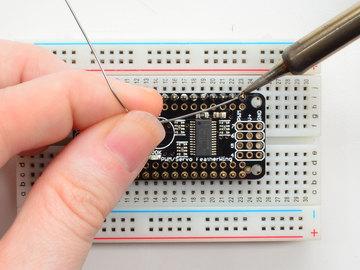
11 Assembly Prepare the header strip: Cut the strip to length if necessary. It will be easier to solder if you insert it into a breadboard - long pins down Adafruit Industries Page 11 of 47


12 Add the FeatherWing: Place the featherwing over the pins so that the short pins poke through the two rows of breakout pads And Solder! Be sure to solder all pins for reliable electrical contact. (For tips on soldering, be sure to check out our Guide to Excellent Soldering ( Start by soldering the first row of header Adafruit Industries Page 12 of 47


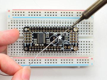
13 Now flip around and solder the other row completely Adafruit Industries Page 13 of 47


14 Adafruit Industries Page 14 of 47


15 You're done with the two header strips. Check your solder joints visually and continue onto the next steps Next we will solder in the larger header blocks used to plug in servos into the FeatherWing. There are two block, each are 3x4 headers in size. The go on either end. Make sure the long side of the headers is facing up! To make it easier to keep these in place, you can use some tape to hold down the two header pieces. Tacky clay also works, whatever you've got handy! Adafruit Industries Page 15 of 47


16 Solder in each block, make sure you get to each of the 12 pins Adafruit Industries Page 16 of 47


17 Now that you're done with the header blocks, check your work make sure that each solder joint is done and looks shiny. Last is the 3.5mm terminal block used for power. This is how you will provide the large amount of current that servos require. Make sure the two open parts of the terminal face outwards so you can easily connect wires Adafruit Industries Page 17 of 47


18 Solder in both pins of the terminal block. You can remove the tape when done. OK You're done! You can now plug in your FeatherWing into your Feather and get servo'ing Adafruit Industries Page 18 of 47

 Feather Stacking Headers (https://adafru.")

19 Stacking Assembly For more controlling than 8 servos, you can stack Servo FeatherWings, but the assembly is a little different. You'll need to grab these products from the shop: 3x4 Right Angle Male Header - 4 pack ( Feather Stacking Headers ( Add the FeatherWing: Place the stacking headers into the FeatherWing so that the long pins poke through the two rows of breakout pads. Make sure the long pins are sticking out underneath the FeatherWing. Adafruit Industries Page 19 of 47

).")
20 To make it easier to keep these in place, you can use some tape to hold down the two header pieces. Tacky clay also works, whatever you've got handy! And Solder! Be sure to solder all pins for reliable electrical contact. (For tips on soldering, be sure to check out ourguide to Excellent Soldering ( Start by soldering the first row of header Adafruit Industries Page 20 of 47

21 Adafruit Industries Page 21 of 47

22 Now flip around and solder the other row completely When you are finished, check that your soldered joints are nice and shiny, then continue to the next step Adafruit Industries Page 22 of 47

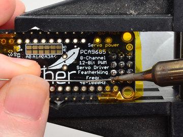
23 Next we will solder in the right angle header blocks used to plug in servos into the FeatherWing. There are two blocks, each are 3x4 headers in size. They go on either end. Make sure the long side of the headers is sticking off the top left & top right sides! Again, use some tape to hold down the two header pieces in place to make soldering easier. Flip it over and solder in each block, make sure you get to each of the 12 pins Adafruit Industries Page 23 of 47

24 Adafruit Industries Page 24 of 47

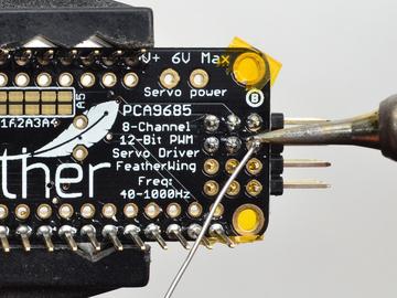
25 Now that you're done with the header blocks, check your work make sure that each solder joint is done and looks shiny. Last is the 3.5mm terminal block used for power. This is how you will provide the large amount of current that servos require. Make sure the two open parts of the terminal face outwards so you can easily connect wires. You'll want to tack down this one too. Adafruit Industries Page 25 of 47

 page for information on selecting an address for each board!")
26 Solder in both pins of the terminal block. Check your work and remove the tape when done. OK You're done! Check out the Advanced Usage ( page for information on selecting an address for each board! Adafruit Industries Page 26 of 47


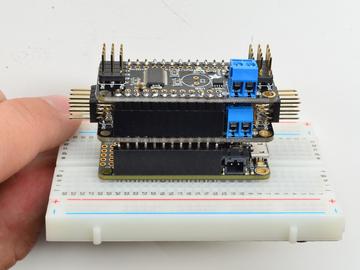
27 You can now stack your FeatherWings and get servo'ing Adafruit Industries Page 27 of 47


28 Using the Adafruit Library Since the PWM Servo Driver is controlled over I2C, its super easy to use with any microcontroller or microcomputer. In this demo we'll show using it with the Arduino IDE but the C++ code can be ported easily Install Adafruit PCA9685 library To begin reading sensor data, you will need to install the Adafruit_PWMServo library (code on our github repository). It is available from the Arduino library manager so we recommend using that. From the IDE open up the library manager... And type in adafruit pwm to locate the library. Click Install We also have a great tutorial on Arduino library installation at: Test with the Example Code: First make sure all copies of the Arduino IDE are closed. Next open the Arduino IDE and select File->Examples->Adafruit_PWMServoDriver->Servo. This will open the example file in an IDE window. Adafruit Industries Page 28 of 47

29 If using a Breakout: Connect the driver board and servo as shown on the previous page. Don't forget to provide power to both Vin (3-5V logic level) and V+ (5V servo power). Check the green LED is lit! If using a Shield: Plug the shield into your Arduino. Don't forget you will also have to provide 5V to the V+ terminal block. Both red and green LEDs must be lit. If using a FeatherWing: Plug the FeatherWing into your Feather. Don't forget you will also have to provide 5V to the V+ terminal block. Check the green LED is lit! Connect a Servo A single servo should be plugged into the PWM #0 port, the first port. You should see the servo sweep back and forth over approximately 180 degrees. Calibrating your Servos Servo pulse timing varies between different brands and models. Since it is an analog control circuit, there is often some variation between samples of the same brand and model. For precise position control, you will want to calibrate the minumum and maximum pulse-widths in your code to match known positions of the servo. Find the Minimum: Using the example code, edit SERVOMIN until the low-point of the sweep reaches the minimum range of travel. It is best to approach this gradually and stop before the physical limit of travel is reached. Find the Maximum: Adafruit Industries Page 29 of 47
30 Again using the example code, edit SERVOMAX until the high-point of the sweep reaches the maximum range of travel. Again, is best to approach this gradually and stop before the physical limit of travel is reached. Use caution when adjusting SERVOMIN and SERVOMAX. Hitting the physical limits of travel can strip the gears and permanently damage your servo. Converting from Degrees to Pulse Length The Arduino "map()" function is an easy way to convert between degrees of rotation and your calibrated SERVOMIN and SERVOMAX pulse lengths. Assuming a typical servo with 180 degrees of rotation; once you have calibrated SERVOMIN to the 0-degree position and SERVOMAX to the 180 degree position, you can convert any angle between 0 and 180 degrees to the corresponding pulse length with the following line of code: pulselength = map(degrees, 0, 180, SERVOMIN, SERVOMAX); Adafruit Industries Page 30 of 47
31 Library Reference setpwmfreq(freq) Description This function can be used to adjust the PWM frequency, which determines how many full 'pulses' per second are generated by the IC. Stated differently, the frequency determines how 'long' each pulse is in duration from start to finish, taking into account both the high and low segments of the pulse. Frequency is important in PWM, since setting the frequency too high with a very small duty cycle can cause problems, since the 'rise time' of the signal (the time it takes to go from 0V to VCC) may be longer than the time the signal is active, and the PWM output will appear smoothed out and may not even reach VCC, potentially causing a number of problems. Arguments freq: A number representing the frequency in Hz, between 40 and 1000 Example The following code will set the PWM frequency to the maximum value of 1000Hz: pwm.setpwmfreq(1000) setpwm(channel, on, off) Description This function sets the start (on) and end (off) of the high segment of the PWM pulse on a specific channel. You specify the 'tick' value between when the signal will turn on, and when it will turn off. Channel indicates which of the 16 PWM outputs should be updated with the new values. Arguments Example channel: The channel that should be updated with the new values (0..15) on: The tick (between ) when the signal should transition from low to high off:the tick (between ) when the signal should transition from high to low The following example will cause channel 15 to start low, go high around 25% into the pulse (tick 1024 out of 4096), transition back to low 75% into the pulse (tick 3072), and remain low for the last 25% of the pulse: pwm.setpwm(15, 1024, 3072) Using as GPIO There's also some special settings for turning the pins fully on or fully off You can set the pin to be fully on with Adafruit Industries Page 31 of 47
32 pwm.setpwm(pin, 4096, 0); You can set the pin to be fully off with pwm.setpwm(pin, 0, 4096); Adafruit Industries Page 32 of 47
33 Arduino Library Docs Arduino Library Docs ( Adafruit Industries Page 33 of 47
34 CircuitPython This guide is for version of the PCA9685 library. Make sure to use a bundle from or later. Adafruit CircuitPython Module Install To use the PCA9685 with your Adafruit CircuitPython board you'll need to install the Adafruit_CircuitPython_PCA9685 module on your board. Remember this module is for Adafruit CircuitPython firmware and not MicroPython.org firmware! First make sure you are running the latest version of Adafruit CircuitPython for your board. Next you'll need to install the necessary libraries to use the hardware--read below and carefully follow the referenced steps to find and install these libraries from Adafruit's CircuitPython library bundle with a version or newer. Bundle Install For express boards that have extra flash storage, like the Feather/Metro M0 express and Circuit Playground express, you can easily install the necessary libraries with Adafruit's CircuitPython bundle. This is an all-in-one package that includes the necessary libraries to use the PCA9685 with CircuitPython. To install the bundle follow the steps in your board's guide, like these steps for the Feather M0 express board. Remember for non-express boards like the Trinket M0, Gemma M0, and Feather/Metro M0 basic you'll need to manually install the necessary libraries from the bundle: adafruit_pca9685 adafruit_bus_device adafruit_register adafruit_motor If your board supports USB mass storage, like the M0-based boards, then simply drag the files to the board's file system. Note on boards without external SPI flash, like a Feather M0 or Trinket/Gemma M0, you might run into issues on Mac OSX with hidden files taking up too much space when drag and drop copying, see this page for a workaround. If your board doesn't support USB mass storage, like the ESP8266, then use a tool like ampy to copy the file to the board. You can use the latest version of ampy and its new directory copy command to easily move module directories to the board. Before continuing make sure your board's lib folder or root filesystem has the adafruit_pca9685, adafruit_bus_device, adafruit_register and adafruit_motor folders/modules copied over. Adafruit Industries Page 34 of 47
35 Usage The following section will show how to control the PCA9685 from the board's Python prompt / REPL. You'll learn how to interactively control servos and dim LEDs by typing in the code below. First connect to the board's serial REPL so you are at the CircuitPython >>> prompt. I2C Initialization First you'll need to initialize the I2C bus for your board. First import the necessary modules: import board import busio Now for either board run this command to create the I2C instance using the default SCL and SDA pins (which will be marked on the boards pins if using a Feather or similar Adafruit board): i2c = busio.i2c(board.scl, board.sda) After initializing the I2C interface you need to import the PCA9685 module to use it in your own code: import adafruit_pca9685 Dimming LED's Each channel of the PCA9685 can be used to control the brightness of an LED. The PCA9685 generates a high-speed PWM signal which turns the LED on and off very quickly. If the LED is turned on longer than turned off it will appear brighter to your eyes. First wire a LED to the board as follows. Note you don't need to use a resistor to limit current through the LED as the PCA9685 will limit the current to around 10mA: Adafruit Industries Page 35 of 47

36 Fritzing Source LED cathode / shorter leg to PCA9685 channel GND / ground. LED anode / longer leg to PCA9685 channel PWM. Now in the Python REPL you can create an instance of the basic PCA9685 class which provides low-level PWM control of the board's channels: pca = adafruit_pca9685.pca9685(i2c) The PCA9685 class provides control of the PWM frequency and each channel's duty cycle. Check out the PCA9685 class documentation for more details. For dimming LEDs you typically don't need to use a fast PWM signal frequency and can set the board's PWM frequency to 60hz by setting the frequency attribute: pca.frequency = 60 The PCA9685 supports 16 separate channels that share a frequency but can have independent duty cycles. That way you could dim 16 LEDs separately! The PCA9685 object has a channels attribute which has an object for each channel that can control the duty cycle. To get the individual channel use the [] to index into channels. Adafruit Industries Page 36 of 47
37 led_channel = pca.channels[0] Now control the LED brightness by controlling the duty cycle of the channel connected to the LED. The duty cycle value should be a 16-bit value, i.e. 0 to 0xffff, which represents what percent of the time the signal is on vs. off. A value of 0xffff is 100% brightness, 0 is 0% brightness, and in-between values go from 0% to 100% brightness. For example set the LED completely on with a duty cycle of 0xffff: led_channel.duty_cycle = 0xffff After running the command above you should see the LED light up at full brightness! Now turn the LED off with a duty cycle of 0: led_channel.duty_cycle = 0 Try an in-between value like 1000: led_channel.duty_cycle = 1000 You should see the LED dimly lit. Try experimenting with other duty cycle values to see how the LED changes brightness! For example make the LED glow on and off by setting duty_cycle in a loop: # Increase brightness: for i in range(0xffff): led_channel.duty_cycle = i # Decrease brightness: for i in range(0xffff, 0, -1): led_channel.duty_cycle = i These for loops take a while because 16-bits is a lot of numbers. CTRL-C to stop the loop from running and return to the REPL. Control Servos Servo motors use a PWM signal to control the position of their arm or horn. Using the PCA9685 and the Motor library you can easily plug in servos and control them with Python. If you aren't familiar with servos be sure to first read this intro to servos page and this in-depth servo guide page. First connect the servo to a channel on the PCA9685. Be sure to plug the servo connector in the correct way! Check your servo's datasheet to be sure, but typically the brown wire is connected to ground, the red wire is connected to 5V power, and the yellow pin is connected to PWM: Adafruit Industries Page 37 of 47

38 Be sure you've turned on or plugged in the external 5V power supply to the PCA9685 board too! Now in the Python REPL as above with the led, save a variable for its channel: servo_channel = pca.channels[0] Servos typically operate at a frequency of 50 hz so update pca accordingly. pca.frequency = 50 Now that the PCA9685 is set up for servos lets make a Servo object so that we can adjust the servo based on angle instead of duty_cycle. By default the Servo class will use actuation range, minimum pulse-width, and maximum pulse-width values that should work for most servos. However check the Servo class documentation for more details on extra parameters to customize the signal generated for your servos. import adafruit_motor.servo servo = adafruit_motor.servo.servo(servo_channel) With Servo, you specify a position as an angle. The angle will always be between 0 and the actuation range given when Servo was created. The default is 180 degrees but your servo might have a smaller sweep--change the total angle by specifying the actuation_angle parameter in the Servo class initializer above. Now set the angle to 180, one extreme of the range: servo.angle = 180 Adafruit Industries Page 38 of 47
39 Or to sweep back to the minimum 0 degree position: servo.angle = 0 Often the range an individual servo recognizes varies a bit from other servos. If the servo didn't sweep the full expected range, then try adjusting min_pulse and max_pulse. Lower min_pulse until the servo stops moving or moves irregularly when angle is changed to 0. Raise max_pulse util the servo stops moving or moves irregularly when angle is change to the actuation range. servo = adafruit_motor.servo.servo(servo_channel, min_pulse=800, max_pulse=2200) That's all there is to controlling servos with the PCA9685 and CircuitPython! Using the angle attribute you can sweep and move servos in any way. This is perfect for building robots, actuating switches, or other fun mechanical projects! Adafruit Industries Page 39 of 47

40 Advanced Usage Adding a Capacitor to the thru-hole capacitor slot We have a spot on the PCB for soldering in an electrolytic capacitor. Based on your usage, you may or may not need a capacitor. If you are driving a lot of servos from a power supply that dips a lot when the servos move, n * 100uF where n is the number of servos is a good place to start - eg 470uF or more for 5 servos. Since its so dependent on servo current draw, the torque on each motor, and what power supply, there is no "one magic capacitor value" we can suggest which is why we don't include a capacitor in the kit. Adding/Stacking Servo Feathers - Using different i2c addresses If you need more Servos, you can stack the FeatherWings (see Stacking Assembly) - each new Wing will give you 8 more Servos You'll need to solder in stacking Feather headers so you can plug more Wings on top! You'll also need to use right-angle 3x4 headers on the Servo Wings so that the servos connect off the ends rather than straight up Each I2C device connected to your Feather must be assigned a unique address. This is done with the address jumpers on the bottom of the board. The I2C base address for each board is 0x40. The binary address that you program with the address jumpers is added to the base I2C address. Adafruit Industries Page 40 of 47
 Board 1: Address = 0x41 Offset = binary 00001 (bridge A0) Board 2: Address = 0x42 Offset")

41 To program the address offset, use a drop of solder to bridge the corresponding address jumper for each binary '1' in the address. Board 0: Address = 0x40 Offset = binary (no jumpers required) Board 1: Address = 0x41 Offset = binary (bridge A0) Board 2: Address = 0x42 Offset = binary (bridge A1) Board 3: Address = 0x43 Offset = binary (bridge A0 & A1) Board 4: Address = 0x44 Offset = binary (bridge A2) etc. See how we do this for the Arduino Shield vesion of this board, its nearly identical: Adafruit Industries Page 41 of 47
42 Adafruit Industries Page 42 of 47
43 FAQ Can this board be used for LEDs or just servos? It can be used for LEDs as well as any other PWM-able device! I am having strange problems when combining this shield with the Adafruit LED Matrix/7Seg Backpacks The PCA9865 chip has an "All Call" address of 0x70. This is in addition to the configured address. Set the backpacks to address 0x71 or anything other than the default 0x70 to make the issue go away. With LEDs, how come I cant get the LEDs to turn completely off? If you want to turn the LEDs totally off use setpwm(pin, 4096, 0); not setpwm(pin, 4095, 0); Adafruit Industries Page 43 of 47
44 Downloads Files PCA9685 Datasheet EagleCad PCB files on GitHub Fritzing object in Adafruit Fritzing library Schematic Click to embiggen Fabrication Print Dimensions in Inches Adafruit Industries Page 44 of 47

45 Adafruit Industries Page 45 of 47
Adafruit 16-Channel Servo Driver with Arduino
 Adafruit 16-Channel Servo Driver with Arduino Created by Bill Earl Last updated on 2018-01-16 12:17:12 AM UTC Guide Contents Guide Contents Overview Pinouts Power Pins Control Pins Output Ports Assembly
Adafruit 16-channel PWM/Servo Shield
 Adafruit 16-channel PWM/Servo Shield Created by lady ada Last updated on 2018-08-22 03:36:11 PM UTC Guide Contents Guide Contents Overview Assembly Shield Connections Pins Used Connecting other I2C devices
Adafruit 16-Channel Servo Driver with Arduino
 Adafruit 16-Channel Servo Driver with Arduino Created by Bill Earl Last updated on 2017-11-26 09:41:23 PM UTC Guide Contents Guide Contents Overview Assembly Install the Servo Headers Solder all pins Add
Adafruit 16-channel PWM/Servo Shield
 Adafruit 16-channel PWM/Servo Shield Created by lady ada Last updated on 2017-06-29 07:25:45 PM UTC Guide Contents Guide Contents Overview Assembly Shield Connections Pins Used Connecting other I2C devices
Adafruit 16-Channel Servo Driver with Arduino
 Adafruit 16-Channel Servo Driver with Arduino Created by Bill Earl Last updated on 2015-09-29 06:19:37 PM EDT Guide Contents Guide Contents Overview Assembly Install the Servo Headers Solder all pins Add
Adafruit 16-Channel PWM/Servo HAT & Bonnet for Raspberry Pi
 Adafruit 16-Channel PWM/Servo HAT & Bonnet for Raspberry Pi Created by lady ada Last updated on 2018-03-21 09:56:10 PM UTC Guide Contents Guide Contents Overview Powering Servos Powering Servos / PWM OR
Adafruit 16-Channel PWM/Servo HAT for Raspberry Pi
 Adafruit 16-Channel PWM/Servo HAT for Raspberry Pi Created by lady ada Last updated on 2017-05-19 08:55:07 PM UTC Guide Contents Guide Contents Overview Powering Servos Powering Servos / PWM OR Current
Adafruit SGP30 TVOC/eCO2 Gas Sensor
 Adafruit SGP30 TVOC/eCO2 Gas Sensor Created by lady ada Last updated on 2018-08-22 04:05:08 PM UTC Guide Contents Guide Contents Overview Pinouts Power Pins: Data Pins Arduino Test Wiring Install Adafruit_SGP30
Introduction to the Arduino Kit
 1 Introduction to the Arduino Kit Introduction Arduino is an open source microcontroller platform used for sensing both digital and analog input signals and for sending digital and analog output signals
Adafruit 16 Channel Servo Driver with Raspberry Pi
 Adafruit 16 Channel Servo Driver with Raspberry Pi Created by Kevin Townsend Last updated on 2014-04-17 09:15:51 PM EDT Guide Contents Guide Contents Overview What you'll need Configuring Your Pi for I2C
Congratulations on your purchase of the SparkFun Arduino ProtoShield Kit!
 Congratulations on your purchase of the SparkFun Arduino ProtoShield Kit! Well, now what? The focus of this guide is to aid you in turning that box of parts in front of you into a fully functional prototyping
Adafruit PCA9685 Library Documentation
 Adafruit PCA9685 Library Documentation Release 1.0 Radomir Dopieralski Aug 25, 2018 Contents 1 Dependencies 3 2 Usage Example 5 3 Contributing 7 4 Building locally 9 4.1 Sphinx documentation..........................................
RGB LED Strips. Created by lady ada. Last updated on :21:20 PM UTC
 RGB LED Strips Created by lady ada Last updated on 2017-11-26 10:21:20 PM UTC Guide Contents Guide Contents Overview Schematic Current Draw Wiring Usage Arduino Code CircuitPython Code 2 3 5 6 7 10 12
Adafruit Si4713 FM Radio Transmitter with RDS/RDBS Support
 Adafruit Si4713 FM Radio Transmitter with RDS/RDBS Support Created by lady ada Last updated on 2016-08-17 03:27:57 AM UTC Guide Contents Guide Contents Overview Pinouts Audio Inputs Power Pins Interface
Pololu Dual G2 High-Power Motor Driver for Raspberry Pi
 Pololu Dual G2 High-Power Motor Driver for Raspberry Pi 24v14 /POLOLU 3752 18v18 /POLOLU 3750 18v22 /POLOLU 3754 This add-on board makes it easy to control two highpower DC motors with a Raspberry Pi.
INSTANT ROBOT SHIELD (AXE408)
") INSTANT ROBOT SHIELD (AXE408) 1.0 Introduction Thank you for purchasing this Instant Robot shield. This datasheet is designed to give a brief introduction to how the shield is assembled, used and configured.
INSTANT ROBOT SHIELD (AXE408) 1.0 Introduction Thank you for purchasing this Instant Robot shield. This datasheet is designed to give a brief introduction to how the shield is assembled, used and configured.
ZX Distance and Gesture Sensor Hookup Guide
 Page 1 of 13 ZX Distance and Gesture Sensor Hookup Guide Introduction The ZX Distance and Gesture Sensor is a collaboration product with XYZ Interactive. The very smart people at XYZ Interactive have created
Name & SID 1 : Name & SID 2:
 EE40 Final Project-1 Smart Car Name & SID 1 : Name & SID 2: Introduction The final project is to create an intelligent vehicle, better known as a robot. You will be provided with a chassis(motorized base),
Cardboard Circuit Playground Express Inchworm Robot
 Cardboard Circuit Playground Express Inchworm Robot Created by Kathy Ceceri Last updated on 2018-10-25 05:41:17 PM UTC Guide Contents Guide Contents Overview Parts List -- Electronics Materials List --
9DoF Sensor Stick Hookup Guide
 Page 1 of 5 9DoF Sensor Stick Hookup Guide Introduction The 9DoF Sensor Stick is an easy-to-use 9 degrees of freedom IMU. The sensor used is the LSM9DS1, the same sensor used in the SparkFun 9 Degrees
Pi Servo Hat Hookup Guide
 Page 1 of 10 Pi Servo Hat Hookup Guide Introduction The SparkFun Pi Servo Hat allows your Raspberry Pi to control up to 16 servo motors via I2C connection. This saves GPIO and lets you use the onboard
가치창조기술. Motors need a lot of energy, especially cheap motors since they're less efficient.
 Overview Motor/Stepper/Servo HAT for Raspberry Pi Let your robotic dreams come true with the new DC+Stepper Motor HAT. This Raspberry Pi add-on is perfect for any motion project as it can drive up to 4
Pololu DRV8835 Dual Motor Driver Kit for Raspberry Pi B+
 Pololu DRV8835 Dual Motor Driver Kit for Raspberry Pi B+ Pololu DRV8835 dual motor driver board for Raspberry Pi B+, top view with dimensions. Overview This motor driver kit and its corresponding Python
Bill of Materials: General Purpose Alarm, Pulsed PART NO
 General Purpose Alarm, Pulsed PART NO. 2190207 I hate alarms that sound continuously - unless they are smoke alarms. Smoke alarms should be annoying, but others should not. I wanted an alarm for a function
APDS-9960 RGB and Gesture Sensor Hookup Guide
 Page 1 of 12 APDS-9960 RGB and Gesture Sensor Hookup Guide Introduction Touchless gestures are the new frontier in the world of human-machine interfaces. By swiping your hand over a sensor, you can control
The Robot Builder's Shield for Arduino
 The Robot Builder's Shield for Arduino by Ro-Bot-X Designs Introduction. The Robot Builder's Shield for Arduino was especially designed to make building robots with Arduino easy. The built in dual motors
Bill of Materials: PWM Stepper Motor Driver PART NO
 PWM Stepper Motor Driver PART NO. 2183816 Control a stepper motor using this circuit and a servo PWM signal from an R/C controller, arduino, or microcontroller. Onboard circuitry limits winding current,
RC Servo Interface. Figure Bipolar amplifier connected to a large DC motor
 The bipolar amplifier is well suited for controlling motors for vehicle propulsion. Figure 12-45 shows a good-sized 24VDC motor that runs nicely on 13.8V from a lead acid battery based power supply. You
TB6612FNG Dual Motor Driver Carrier
 TB6612FNG Dual Motor Driver Carrier Overview The TB6612FNG (308k pdf) is a great dual motor driver that is perfect for interfacing two small DC motors such as our micro metal gearmotors to a microcontroller,
Stereo 3.7W Class D Audio Amplifier
 Stereo 3.7W Class D Audio Amplifier Created by Bill Earl Last updated on 2014-10-28 10:45:16 AM EDT Guide Contents Guide Contents Overview Specifications: What is a Class D Amplifier? Other Audio amps
tinycylon Assembly Instructions Contents Written by Dale Wheat Version August 2016 Visit dalewheat.com for the latest update!
 tinycylon Assembly Instructions Written by Dale Wheat Version 2.1 10 August 2016 Visit dalewheat.com for the latest update! Contents Assembly Instructions...1 Contents...1 Introduction...2 Quick Start
100UF CAPACITOR POTENTIOMETER SERVO MOTOR MOTOR ARM. MALE HEADER PIN (3 pins) INGREDIENTS
 INGREDIENTS") 05 POTENTIOMETER SERVO MOTOR MOTOR ARM 100UF CAPACITOR MALE HEADER PIN (3 pins) INGREDIENTS 63 MOOD CUE USE A SERVO MOTOR TO MAKE A MECHANICAL GAUGE TO POINT OUT WHAT SORT OF MOOD YOU RE IN THAT DAY Discover:
05 POTENTIOMETER SERVO MOTOR MOTOR ARM 100UF CAPACITOR MALE HEADER PIN (3 pins) INGREDIENTS 63 MOOD CUE USE A SERVO MOTOR TO MAKE A MECHANICAL GAUGE TO POINT OUT WHAT SORT OF MOOD YOU RE IN THAT DAY Discover:
The µbotino Microcontroller Board
 The µbotino Microcontroller Board by Ro-Bot-X Designs Introduction. The µbotino Microcontroller Board is an Arduino compatible board for small robots. The 5x5cm (2x2 ) size and the built in 3 pin connectors
Sunday, November 4, The LadyUno Sound Unit
 The LadyUno Sound Unit Here s what we ll need for this project We start with our finished Lady Ada Wav Shield. 5V for LCD Serial Data for LCD GND for LCD 5V (coming from the BBB) is_lady_ada_busy PIN GND
Milli Developer Kit Reference Application Published on Silver Spring Networks STAGE (
 Milli Developer Kit Example Application PART 1 Example CoAP Server Sensor Implementation With The Milli Dev Kit Get the Milli Developer Kit Temperature Sensor Reference Application on GitHub [1] This reference
Demon Pumpkin APPROXIMATE TIME (EXCLUDING PREPARATION WORK): 1 HOUR PREREQUISITES: PART LIST:
: 1 HOUR PREREQUISITES: PART LIST:") Demon Pumpkin This is a lab guide for creating your own simple animatronic pumpkin. This project encourages students and makers to innovate upon the base design to add their own personal touches. APPROXIMATE
Demon Pumpkin This is a lab guide for creating your own simple animatronic pumpkin. This project encourages students and makers to innovate upon the base design to add their own personal touches. APPROXIMATE
Bill of Materials: Metronome Kit PART NO
 Metronome Kit PART NO. 2168325 The metronome kit allows you to build your own working electronic metronome. Features include a small speaker, flashing LED, and the ability to switch between several different
QUASAR PROJECT KIT # /24 HOUR GIANT CLOCK
 This project was originally published in the electronics magazine, Silicon Chip, a few years ago. It is issued here as a kit with permission. Some modifications to the original published circuit and software
MD04-24Volt 20Amp H Bridge Motor Drive
 MD04-24Volt 20Amp H Bridge Motor Drive Overview The MD04 is a medium power motor driver, designed to supply power beyond that of any of the low power single chip H-Bridges that exist. Main features are
POLOLU DUAL MC33926 MOTOR DRIVER FOR RASPBERRY PI (ASSEMBLED) USER S GUIDE
 USER S GUIDE") POLOLU DUAL MC33926 MOTOR DRIVER FOR RASPBERRY PI (ASSEMBLED) DETAILS FOR ITEM #2756 USER S GUIDE This version of the motor driver is fully assembled, with a 2 20-pin 0.1 female header (for connecting
POLOLU DUAL MC33926 MOTOR DRIVER FOR RASPBERRY PI (ASSEMBLED) DETAILS FOR ITEM #2756 USER S GUIDE This version of the motor driver is fully assembled, with a 2 20-pin 0.1 female header (for connecting
Circuit Board Assembly Instructions for Babuinobot 1.0
 Circuit Board Assembly Instructions for Babuinobot 1.0 Brett Nelson January 2010 1 Features Sensor4 input Sensor3 input Sensor2 input 5v power bus Sensor1 input Do not exceed 5v Ground power bus Programming
1 Introduction. 2 Embedded Electronics Primer. 2.1 The Arduino
 Beginning Embedded Electronics for Botballers Using the Arduino Matthew Thompson Allen D. Nease High School matthewbot@gmail.com 1 Introduction Robotics is a unique and multidisciplinary field, where successful
INA169 Breakout Board Hookup Guide
 Page 1 of 10 INA169 Breakout Board Hookup Guide CONTRIBUTORS: SHAWNHYMEL Introduction Have a project where you want to measure the current draw? Need to carefully monitor low current through an LED? The
Tarocco Closed Loop Motor Controller
 Contents Safety Information... 3 Overview... 4 Features... 4 SoC for Closed Loop Control... 4 Gate Driver... 5 MOSFETs in H Bridge Configuration... 5 Device Characteristics... 6 Installation... 7 Motor
Assembly Manual for VFO Board 2 August 2018
 Assembly Manual for VFO Board 2 August 2018 Parts list (Preliminary) Arduino 1 Arduino Pre-programmed 1 Faceplate Assorted Header Pins Full Board Rev A 10 104 capacitors 1 Rotary encode with switch 1 5-volt
Jaguar Motor Controller (Stellaris Brushed DC Motor Control Module with CAN)
") Jaguar Motor Controller (Stellaris Brushed DC Motor Control Module with CAN) 217-3367 Ordering Information Product Number Description 217-3367 Stellaris Brushed DC Motor Control Module with CAN (217-3367)
Jaguar Motor Controller (Stellaris Brushed DC Motor Control Module with CAN) 217-3367 Ordering Information Product Number Description 217-3367 Stellaris Brushed DC Motor Control Module with CAN (217-3367)
Servo click. PID: MIKROE 3133 Weight: 32 g
 Servo click PID: MIKROE 3133 Weight: 32 g Servo click is a 16-channel PWM servo driver with the voltage sensing circuitry. It can be used to simultaneously control 16 servo motors, each with its own programmable
Sten-Bot Robot Kit Stensat Group LLC, Copyright 2013
 Sten-Bot Robot Kit Stensat Group LLC, Copyright 2013 Legal Stuff Stensat Group LLC assumes no responsibility and/or liability for the use of the kit and documentation. There is a 90 day warranty for the
Build a Mintronics: MintDuino
 Build a Mintronics: MintDuino Author: Marc de Vinck Parts relevant to this project Mintronics: MintDuino (1) The MintDuino is perfect for anyone interested in learning (or teaching) the fundamentals of
QLG1 GPS Receiver kit
 QLG1 GPS Receiver kit 1. Introduction Thank you for purchasing the QRP Labs QLG1 GPS Receiver kit. This kit will provide a highly sensitive, highly accurate GPS receiver module, using the popular MediaTek
Welcome! Welcome to the LVL1 TV-B-Gone workshop. We will be covering the following: How the TV-B-Gone works Basic soldering technique Component identi
 TV-B-Gone LVL1 Welcome! Welcome to the LVL1 TV-B-Gone workshop. We will be covering the following: How the TV-B-Gone works Basic soldering technique Component identification Construction of a Super TV-B-Gone
Adafruit's Raspberry Pi Lesson 8. Using a Servo Motor
 Adafruit's Raspberry Pi Lesson 8. Using a Servo Motor Created by Simon Monk Last updated on 2016-11-03 06:17:53 AM UTC Guide Contents Guide Contents Overview Parts Part Qty Servo Motors Hardware Software
Assembly notes for RFX Teensy 3.x carrier board
 Assembly notes for RFX Teensy 3.x carrier board Mark Pendrith , Dec 2014. Basic kit parts (BOM) 1 PCB mount 5mm/2.1mm DC barrel jack (see note below) 1 LD1117v33 1 1N5817
Spy Theme Playback Device
 Spy Theme Playback Device Created by John Park Last updated on 2018-04-06 09:10:16 PM UTC Guide Contents Guide Contents Overview Code Music with MakeCode for Circuit Playground Express Building the Gemma
High Current DC Motor Driver Manual
 High Current DC Motor Driver Manual 1.0 INTRODUCTION AND OVERVIEW This driver is one of the latest smart series motor drivers designed to drive medium to high power brushed DC motor with current capacity
Brushed DC Motor Control. Module with CAN (MDL-BDC24)
") Stellaris Brushed DC Motor Control Module with CAN (MDL-BDC24) Ordering Information Product No. MDL-BDC24 RDK-BDC24 Description Stellaris Brushed DC Motor Control Module with CAN (MDL-BDC24) for Single-Unit
Stellaris Brushed DC Motor Control Module with CAN (MDL-BDC24) Ordering Information Product No. MDL-BDC24 RDK-BDC24 Description Stellaris Brushed DC Motor Control Module with CAN (MDL-BDC24) for Single-Unit
EL Wire. Created by lady ada. Last updated on :43:11 PM UTC
 EL Wire Created by lady ada Last updated on 2017-12-26 05:43:11 PM UTC Guide Contents Guide Contents Overview Quickstart FAQ Soldering to EL Wire Using EL Wire Drivers EL Wire Modeling Current Draw Inverter
Mechatronics Engineering and Automation Faculty of Engineering, Ain Shams University MCT-151, Spring 2015 Lab-4: Electric Actuators
 Mechatronics Engineering and Automation Faculty of Engineering, Ain Shams University MCT-151, Spring 2015 Lab-4: Electric Actuators Ahmed Okasha, Assistant Lecturer okasha1st@gmail.com Objective Have a
ScaleRCHelis.com V Light Controller Kit
 Thank you for purchasing the ScaleRCHelis.com V1.1 450 Light Controller Kit. This is something you can build in under a hour with some simple soldering equipment. Your kit will include all the parts necessary
LED Infinity Mirror Controller, 32 LEDs, Multiple Patterns.
 http://wwwinstructablescom/id/led-infinity-mirror-controller-32-leds-multiple-/ Food Living Outside Play Technology Workshop LED Infinity Mirror Controller, 32 LEDs, Multiple Patterns by ChromationSystems
Controlling DC Brush Motor using MD10B or MD30B. Version 1.2. Aug Cytron Technologies Sdn. Bhd.
 PR10 Controlling DC Brush Motor using MD10B or MD30B Version 1.2 Aug 2008 Cytron Technologies Sdn. Bhd. Information contained in this publication regarding device applications and the like is intended
Build this Direct Digital Synthesizer "Development Kit" By: Diz Gentzow, W8DIZ
 Build this Direct Digital Synthesizer "Development Kit" By: Diz Gentzow, W8DIZ A great tutorial for adding a keypad to the DDS Kit by Bruce, W8BH This manual has been prepared to be read directly on screen.
ESE141 Circuit Board Instructions
 ESE141 Circuit Board Instructions Board Version 2.1 Fall 2006 Washington University Electrical Engineering Basics Because this class assumes no prior knowledge or skills in electrical engineering, electronics
Guide to LED and Hobby Lighting Projects Documentation
 Guide to LED and Hobby Lighting Projects Documentation Release 0.1.2 Brian Luft Nov 06, 2017 Contents 1 Set Your Goals and Expectations 3 1.1 Introduction...............................................
Ardweeny 1.60" 0.54" Simple construction - only 7 parts plus pins & PCB! Ideal for breadboard applications
 Ardweeny tm Arduino -compatible Microcontroller Like to build your own breadboard-compatible Arduino? Get all the basic features of Arduino in a tidy, cost-effectve package! Build Time: 20mins Skill Level:
EE283 Electrical Measurement Laboratory Laboratory Exercise #7: Digital Counter
 EE283 Electrical Measurement Laboratory Laboratory Exercise #7: al Counter Objectives: 1. To familiarize students with sequential digital circuits. 2. To show how digital devices can be used for measurement
Basic Electronics Course Part 2
 Basic Electronics Course Part 2 Simple Projects using basic components Including Transistors & Pots Following are instructions to complete several electronic exercises Image 7. Components used in Part
ScaleRCHelis.com Light Controller Users Manual
 This manual is for both the 450 and High Power light controllers. The difference between the two controllers: The 450 controller is only single input allowing the user to directly control the landing and
EE-110 Introduction to Engineering & Laboratory Experience Saeid Rahimi, Ph.D. Labs Introduction to Arduino
 EE-110 Introduction to Engineering & Laboratory Experience Saeid Rahimi, Ph.D. Labs 10-11 Introduction to Arduino In this lab we will introduce the idea of using a microcontroller as a tool for controlling
EVDP610 IXDP610 Digital PWM Controller IC Evaluation Board
 IXDP610 Digital PWM Controller IC Evaluation Board General Description The IXDP610 Digital Pulse Width Modulator (DPWM) is a programmable CMOS LSI device, which accepts digital pulse width data from a
SB Protoshield v1.0. -Compatible Prototyping & Breadboard Shield Design and build your own interface for your Arduino-compatible microcontroller!
 SB Protoshield v1.0 tm Arduino -Compatible Prototyping & Breadboard Shield Design and build your own interface for your Arduino-compatible microcontroller! Build Time: 30mins Skill Level: Beginner (2/5)
Electronic Components
 Electronic Components Arduino Uno Arduino Uno is a microcontroller (a simple computer), it has no way to interact. Building circuits and interface is necessary. Battery Snap Battery Snap is used to connect
Cardboard Box for Circuit Playground Express
 Cardboard Box for Circuit Playground Express Created by Ruiz Brothers Last updated on 2018-08-22 04:07:28 PM UTC Guide Contents Guide Contents Overview Cardboard Project for Students Fun PaperCraft! Electronic
Inspiring Creative Fun Ysbrydoledig Creadigol Hwyl. S4A - Scratch for Arduino Workbook
 Inspiring Creative Fun Ysbrydoledig Creadigol Hwyl S4A - Scratch for Arduino Workbook 1) Robotics Draw a robot. Consider the following and annotate: What will it look like? What will it do? How will you
CMU232 User Manual Last Revised October 21, 2002
 CMU232 User Manual Last Revised October 21, 2002 Overview CMU232 is a new low-cost, low-power serial smart switch for serial data communications. It is intended for use by hobbyists to control multiple
Heartboard PCB Assembly Instructions
 Heartboard PCB Assembly Instructions Thanks for purchasing a Heartboard! These instructions will guide you through assembling and testing the Heartboard. Let s get started! Stuff you need Soldering iron
Lab Exercise 9: Stepper and Servo Motors
 ME 3200 Mechatronics Laboratory Lab Exercise 9: Stepper and Servo Motors Introduction In this laboratory exercise, you will explore some of the properties of stepper and servomotors. These actuators are
BINARY. Logic functions for analog computation DIY BUILD GUIDE GRAYSCALE.
 BINARY Logic functions for analog computation DIY BUILD GUIDE GRAYSCALE http://grayscale.info BINARY DIY BUILD GUIDE Binary from Grayscale is a 1-bit analog computer for digital logic signals. Patch up
ESE 350 HEXAWall v 2.0 Michelle Adjangba Omari Maxwell
 ESE 350 HEXAWall v 2.0 Michelle Adjangba Omari Maxwell Abstract This project is a continuation from the HEXA interactive wall display done in ESE 350 last spring. Professor Mangharam wants us to take this
Compact Motor Driver Robot Shield
 Compact Motor Driver Robot Shield Build Time: 25 mins Skill Level: Beginner (2/5) Here s your task - putting Arduino brains into the soulless shell of your mechanical monster. Ah, but what are brains without
ZKit-51-RD2, 8051 Development Kit
 ZKit-51-RD2, 8051 Development Kit User Manual 1.1, June 2011 This work is licensed under the Creative Commons Attribution-Share Alike 2.5 India License. To view a copy of this license, visit http://creativecommons.org/licenses/by-sa/2.5/in/
TWEAK THE ARDUINO LOGO
 TWEAK THE ARDUINO LOGO Using serial communication, you'll use your Arduino to control a program on your computer Discover : serial communication with a computer program, Processing Time : 45 minutes Level
Figure 1. CheapBot Smart Proximity Detector
 The CheapBot Smart Proximity Detector is a plug-in single-board sensor for almost any programmable robotic brain. With it, robots can detect the presence of a wall extending across the robot s path or
Trademarks & Copyright
 Smart Peripheral Controller Neo DC Motor 1.2A Trademarks & Copyright AT, IBM, and PC are trademarks of International Business Machines Corp. Pentium is a registered trademark of Intel Corporation. Windows
N3ZI Kits General Coverage Receiver, Assembly & Operations Manual (For Jun 2011 PCB ) Version 3.33, Jan 2012
 Version 3.33, Jan 2012") N3ZI Kits General Coverage Receiver, Assembly & Operations Manual (For Jun 2011 PCB ) Version 3.33, Jan 2012 Thank you for purchasing my general coverage receiver kit. You can use the photo above as a
N3ZI Kits General Coverage Receiver, Assembly & Operations Manual (For Jun 2011 PCB ) Version 3.33, Jan 2012 Thank you for purchasing my general coverage receiver kit. You can use the photo above as a
UCL Micro:bit Robotics Documentation
 UCL Micro:bit Robotics Documentation Release 0.1 Rae Harbird Sep 25, 2018 Contents 1 Building Your Own Robots 3 2 Contents 5 2.1 Micro:bit - Getting Started........................................ 5 2.2
AS726X NIR/VIS Spectral Sensor Hookup Guide
 Page 1 of 9 AS726X NIR/VIS Spectral Sensor Hookup Guide Introduction The AS726X Spectral Sensors from AMS brings a field of study to consumers that was previously unavailable, spectroscopy! It s now easier
EECS 270: Lab 7. Real-World Interfacing with an Ultrasonic Sensor and a Servo
 EECS 270: Lab 7 Real-World Interfacing with an Ultrasonic Sensor and a Servo 1. Overview The purpose of this lab is to learn how to design, develop, and implement a sequential digital circuit whose purpose
Smart Circuits: Lights On!
 Smart Circuits: Lights On! MATERIALS NEEDED JST connector for use with the Gemma Breadboard Gemma Mo Alligator to jumper Jumper wires Alligator to alligator 2 MATERIALS NEEDED Copper tape Photo sensor
RC Interface Controller Board Assembly and Operation
 RC Interface Controller Board Assembly and Operation Revision Date: January 17, 2006 SUPERDROIDROBOTS.COM RC Interface Controller Board Accurate content is of the utmost importance to the authors of this
Hobby Servo Tutorial. Introduction. Sparkfun: https://learn.sparkfun.com/tutorials/hobby-servo-tutorial
 Hobby Servo Tutorial Sparkfun: https://learn.sparkfun.com/tutorials/hobby-servo-tutorial Introduction Servo motors are an easy way to add motion to your electronics projects. Originally used in remotecontrolled
Pic-Convert Board Instructions
 Pic-Convert Board Instructions This is the fifth version of the Pic-Convert board and now has fully isolated inputs and provides a power supply to make the solution completely industrial. This DAC+PWM
Getting Started with the micro:bit
 Page 1 of 10 Getting Started with the micro:bit Introduction So you bought this thing called a micro:bit what is it? micro:bit Board DEV-14208 The BBC micro:bit is a pocket-sized computer that lets you
Coding with Arduino to operate the prosthetic arm
 Setup Board Install FTDI Drivers This is so that your RedBoard will be able to communicate with your computer. If you have Windows 8 or above you might already have the drivers. 1. Download the FTDI driver
OpenROV. Guide 3 - Electronics. We will now move to the assembly of the electronics that will control the ROV. Written By: OpenROV
 OpenROV Guide 3 - Electronics We will now move to the assembly of the electronics that will control the ROV. Written By: OpenROV 2017 openrov.dozuki.com Page 1 of 33 INTRODUCTION We will introduce soldering
RGB Driver click. PID: MIKROE 3078 Weight: 28 g
 RGB Driver click PID: MIKROE 3078 Weight: 28 g RGB Driver click is an RGB LED driver, capable of driving RGB LED stripes, LED fixtures and other RGB LED applications that demand an increased amount of
PS2-SMC-06 Servo Motor Controller Interface
 PS2-SMC-06 Servo Motor Controller Interface PS2-SMC-06 Full Board Version PS2 (Playstation 2 Controller/ Dual Shock 2) Servo Motor Controller handles 6 servos. Connect 1 to 6 Servos to Servo Ports and
Lab 2: Blinkie Lab. Objectives. Materials. Theory
 Lab 2: Blinkie Lab Objectives This lab introduces the Arduino Uno as students will need to use the Arduino to control their final robot. Students will build a basic circuit on their prototyping board and
Lesson 3: Arduino. Goals
 Introduction: This project introduces you to the wonderful world of Arduino and how to program physical devices. In this lesson you will learn how to write code and make an LED flash. Goals 1 - Get to
TekBot Remote Control Receiver Board Construction
 TekBot Remote Control Receiver Board Construction Purpose This tutorial illustrates the procedure for construction of the Receiver board for the TekBot. A Guide to Soldering Many of you have soldered once