Motorola Solutions PTP. LINK Planning Factors that determine your PTP Solution
|
|
|
- Susanna Carpenter
- 6 years ago
- Views:
Transcription

1 Motorola Solutions PTP LINK Planning Factors that determine your PTP Solution

2 Agenda Motorola PTP Solutions Key Questions Propagation Effects Freespace Loss Atmospheric Absorption Rain Fade Clear Air Fading PTP LINKPlanner Motorola PTP Products 2


3 WIDE RANGE OF MOTOROLA PTP OPTIONS License-Exempt and Defined-Use Licensed Solutions Licensed Solutions PTP 100 and 200 PTP 300, 500, 600 PTP to 5.9 GHz 6 to 38 GHz 3
4 How do I decide? What is the range? What is the throughput at that range? What is the availability? The answers to all these questions depend on a number of factors, and change depending where the link is deployed. 4
5 Key Propagation Effects Atmospheric multipath fading due to abnormal refraction Attenuation due to rain / snow / dust Line-of-sight (LOS), freespace attenuation + atmospheric gas (Oxygen, water vapour) Distortion due to frequency selective fading Fading due to Multipath from surface reflection Diffraction Fading due to obstruction of path by terrain 5 Modelled according to ITU-R P.530
6 Microwave link planning As in [ITU-R P.530], propagation loss consists of: Freespace loss Lfs Gaseous absorption Lg Rain Lr Clear-air fading (multipath) Lm Loss (db) = Lfs + Lg + Lm + Lr 6
7 Freespace Pathloss L fs = log( d) + 20 log( f ) d = distance (km) f = frequency (MHz) Perfect Omni antenna High-gain antennas at high freqs 900 MHz 32dB 26 GHz 26 GHz 5 GHz 15dB 0dB 5 GHz 900 MHz 7
8 Atmospheric Absorption P = 1013 hpa T = 20 o C ρ = 7.5 g/m 3 Atmospheric Attenuation Factor o (db/km) Dry gas Water vapour Total GHz Oxygen absorption peak Attenuation factor (db/km) MOTOROLA and the Stylized M Logo are registered in the US Patent & Trademark Office. All other product Frequency or service (GHz)
9 Key propagation effects above 6 GHz 1. Rain : can be severe 2. Clear-air fading (includes ducting) : can be severe 3. Obstacles and multipath : Unlicensed only for non-los Fresnel zone should be clear for Licensed 9 Licenced Mircrowave (PTP800) is designed for clear LOS operation only!!!


10 H 2 O is a polar molecule with a separation of charge, so it is affected by microwaves Rain Fade Freq (GHz) ¼ wavelength mm mm mm mm When raindrop size gets close to wavelength you get power absorption Water drop mm Water drop on a leaf Raindrop falling through air < 2 mm Photo: M.Sellars Surface tension forms pendant shape 10 Photo: M.Sellars Sphere is the shape with smallest surface area Air resistance causes bottom of raindrop to flatten Horizontal dimension is biggest, so Horizontal polarisation interacts more Largest raindrops about 9 mm > 2 mm 5 mm
11 99.99% Rain fade depth (db) Rain fade for V & H Polarisation Horizontal polarisation is more attenuated by rain 18 GHz 23 GHz Large gap between V and H polarisation 5 GHz Rain rate 42 mm/hour Vertical, 5 GHz Horizontal, 5GHz Vertical, 18 GHz Horizontal, 18 GHz Vertical, 23 GHz Horizontal, 23 GHz Distance (km)
12 Rain Fading For a 99.99% link need to know max rain rate not exceeded for 99.99% of the time then calculate path loss due to this amount of rain Cambridge U.K. Johannesburg South Africa Kuala Lumpur Malaysia Bombay India Dar es Salaam Tanzania Sydney Australia Lattitude 52.2 N 26.1 S 3.2 N 18.6 N 6.5 S 33.9 S Longitude 0.1 E 28.0 E E 74.4 E 39.2 E E Rainfall rate R 0.01 = 0.01% 22 mm/hr 51 mm/hr 116 mm/hr 74 mm/hr 95.5 mm/hr 45.9 mm/hr 12
13 99.99% Rain fade (Morocco 29mm/hour) Rain fade (db) Link length (km) 13
14 99.99% Rain fade (Malaysia 98mm/hour) Rain fade (db) Link length (km) 14
15 Clear-air fading Fading NOT due to rain, particles, obstacles (trees, buildings) => CLEAR AIR fading Caused by extremely refractive layers of air in the atmosphere According to ITU-R P , clear-air fading mechanisms include : Beam spreading (commonly referred to as defocusing) Antenna decoupling Surface multipath Atmospheric multipath These mechanisms can occur by themselves or in combination 15
16 Duct = Extremely refractive layer of air Top of duct Earth surface Ducts in atmosphere due to changing refractive index Cause radio waves to bend back towards the earth surface Primarily due to water vapour, worst above coastal areas Gradient of refractive index dn/dh = -39 units/km (linear) Change in temperature -> ducts change -> refractive index changes True Earth Equivalent earth Flat Earth (standard atmosphere) 0 0 linear Rays return to earth

17 Clear air fading ITU combines all types of clear-air fading Not correlated with rain, so fading effects considered independent Based on data of refractive index - Can vary depending on the season eg worst in summer months in UK Use refractivity gradient to estimate probability of ducting as in ITU-R P.453 Cambridge U.K. Johannesburg South Africa Abu-Dhabi UAE Bombay India Dar es Salaam Tanzania Sydney Australia Refractivity index dn 1 Geoclimatic factor K 2.6e-4 3.6e e-4 3.3e-4 1.4e-3 17
18 Clear-air fading depends on: Ducts broken-up Latitude Altitude Surface roughness Inclination angle Frequency worse at equator worse at sea-level worse over flat ground worse on flat path worse at high frequency Transmission path cuts across ducts, => little refraction Transmission path lies inside a duct Ducts form easily and persist Mountains - Low fading 18 Flat coastal - High fading
19 99.99% Clear-air fade (Ashburton, U.K. vs Abu-Dhabi) Abu-Dhabi 5.8 Abu-Dhabi 8.0 Abu-Dhabi 11 Abu-Dhabi 18 Abu-Dhabi 23 Abu-Dhabi 26 Abu-Dhabi Abu-Dhabi Fade (db) Ashburton, U.K Link length (km)
20 RSL U.K. Clear-air fading RSL Abu-Dhabi Clear-air fading mean mean 24dB 0.01% fade 61dB time time 0.01% fade 99.99% Clear-air fade (Ashburton, U.K. vs. Abu-Dhabi) U.K. 8 GHz Abu-Dhabi 8 GHz Abu-Dhabi, at 40km, 8GHz signal will fade by 61dB for 0.01% of time 60.0 Fade (db) U.K., at 40km, 8GHz signal will fade by 24dB for 0.01% of time Link length (km) 20 LINKPlanner calculates this automatically
21 Winnipeg, Canada: 99.99% Fading (Rain and Clear-air) Rain 5.8 Rain 8 Rain 11 Rain 18 Rain 23 Rain 26 Rain 38 CA 5.8 CA 8 CA 11 CA 18 CA 23 CA 26 CA Fade (db) Rain 23GHz Rain 18GHz Clear-air fading Link length (km)
 Salt Lake City 21 0.055 Seattle San Diego 25 0.190 Phoenix 33 0.130 Boston Dodge City 36 0.170 Boston 41 0.329 Schaumburg 41 0.230 Seattle 41 0.091 Charlottesville 51 0.")
22 Geographical variations Sometimes rain dominates (usually at higher frequencies), whereas clear-air fading may dominate near the coast City Rain (mm/hr) Geoclimatic Factor K ( x ) Salt Lake City Seattle San Diego Phoenix Boston Dodge City Boston Schaumburg Seattle Charlottesville Salt Lake City San Diego Phoenix Dodge City Schaumburg Charlottesville Dallas Lake Mary GeorgeTown, Gr. Cayman Dallas Lake Mary Depends on intensity of heaviest rainstorm NOT frequent drizzle High values above 0.2 mean high ducting GeorgeTown Grand Cayman 22
23 99.99% Rain fade depth Fading calculations for USA - RAIN Rain fade worst in areas of heavy storms (Florida) USA Rain Fade Link distance (km) 18GHz 6GHz 11GHz Boston 6GHz Boston 11GHz Boston 18GHz Dallas 6GHz Dallas 11GHz Dallas 18GHz Dodge City 6GHz Dodge City 11GHz Dodge City 18GHz Lake Mary 6GHz Lake Mary 11GHz Lake Mary 18GHz Phoenix 6GHz Phoenix 11GHz Phoenix 18GHz Salt Lake City 6GHz Salt Lake City 11GHz Salt Lake City 18GHz 23 Lower frequencies not affected much by rain
24 Fading calculations for USA Clear-air USA Clear-air fade 99.99% Fade depth Clear-air fading worst on coast (Boston, Cayman Isl) Best in Salt Lake City (high altitude, mountains, inland) Link distance (km) Boston 6GHz Boston 11GHz Boston 18GHz GT Cayman Is. 6GHz GT Cayman Is. 11GHz GT Cayman Is. 18GHz Seattle 6GHz Seattle 11GHz Seattle 18GHz Phoenix 6GHz Phoenix 11GHz Phoenix 18GHz Salt Lake City 6GHz Salt Lake City 11GHz Salt Lake City 18GHz
25 Fading calculations for USA Rain and Ducting combined Link Distances for 99.99% Availability, 256-QAM, 6-foot dish Frequency (GHz) 18GHz Salt Lake City Phoenix GeorgeTown, G.Cayman Boston Lake Mary Dominated by rain fading, worst in stormy areas (GeorgeTown) Salt Lake City has lowest rainfall so high frequencies travel quite far 18 GHz in Salt Lake City travels further than 6 or 11 GHz in most other places! 11GHz FCC Rules for 11 GHz: Smallest antenna = 2.6ft Shortest path = 5 km 6 GHz Dominated by clear-air fading, worst on coast (Lake Mary) FCC Rules for 6 GHz: Smallest antenna = 6ft Shortest path = 17 km Distance (km) Salt Lake City is in the mountains so clear-air fading is low
26 Simple Questions? What is the range? What is the throughput at that range? What is the availability? There is no quick answer to these questions, a lot depends on your location and a number of factors for your link Calculating these factors manually would be very time consuming! 26

27 27
28 MOTOROLA LINKPlanner software Link planning should be carried out BEFORE equipment purchase / install Download the FREE tool from Start the PTP LINKPlanner tool 28 Create sites Create links Request path data from Motorola Free 3 metre Terrain Data (US Only, 10 metre world wide) Aerial Photography (free from Google Earth) Load obstruction data into link tools Obstructions estimated from aerial photography and local knowledge Estimate antenna heights Estimate appropriate antenna sizes Estimate environmental noise Configure link for customer needs

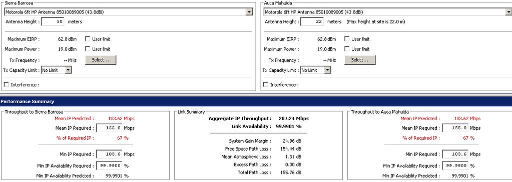
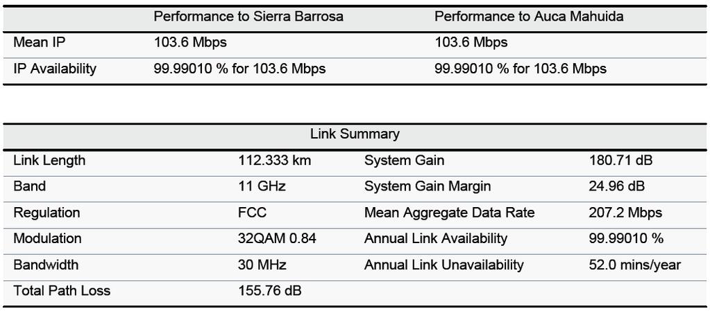
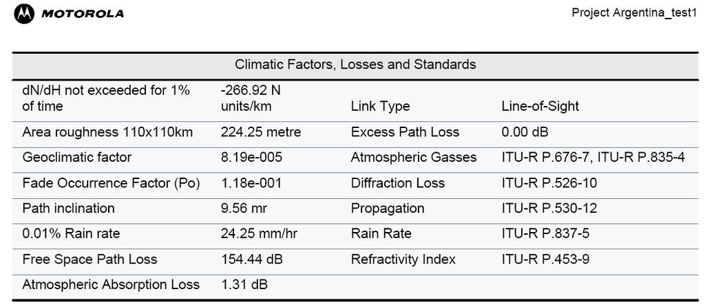
29 Long link, 112km 29
30 30
 28GHz, d=10km, F n 5m d 1 F n d 2 Fn = nλd")

31 Fresnel zone clear if possible PTP 800 is designed for clear LOS operation only!!! Width of First Fresnel zone (n=1) 28GHz, d=10km, F n 5m d 1 F n d 2 Fn = nλd 1d d + d Curvature of Earth Radius of Earth 6371km Effective Earth Radius factor typically 4/3 bulge 1.5m for d=10km ITU-R P.526 model for irregular terrain 31
32 Guidance for PTP 800 link distances Distances calculated for various frequencies assuming: 128QAM, 99.99%, 4-foot dishes, medium fading (rain = 58 mm/hr, refractive index dn1 = -219) Frequency (GHz) 38 Short, high-capacity links Minimum link dist ~ 0.5km 26 Short, high-capacity links 23 Short, high-capacity links 18 Medium links 15 Medium links 11 6 Regulator may not license < 5km or 17km (FCC) Long trunks Long trunks Unlicensed Distance (km)
33 PRODUCTS AND KEY FEATURES PTP Feature PTP 100 PTP 200 PTP 300 PTP 500 PTP 600 PTP RF bands (GHz) Max. Throughput Max. LOS Range Max. NLOS Range Security Wind Speed Survival Operating Temperature 2.4, 5.2, 5.4, Mbps 21 Mbps 35 mi (56 km) with reflector 4.9, , , mi (8 km) Integrated antenna 25 Mbps 50 Mbps LOS option 155 mi (250 km) 2.5, 4.5, 4.8, 4.9, 5.4, 5.8, Mbps 300 Mbps 155 mi (250 km) 124 mi (200 km) Mbps (full duplex) NA NA 6 mi (10 km) 6 mi (10 km) 5 mi (8 km) NA 56-bit DES 128-bit AES 118 mph (190 kph) -40º~131º F (-40º~55º C) 56-bit DES 128-bit AES 118 mph (190 kph) -40º ~131º F (-40º~55º C) 128/256-bit AES 202 mph (325 kph) -40º~140º F (-40º~60º C) 128/256-bit AES 202 mph (325 kph) -40º~140º F (-40º~60º C) 128/256-bit AES; FIPS mph (325 kph) -40º~140º F (-40º~60º C) NA 128/256-bit AES 150 mph (242 kph) -27º~131º F (-33º~55º C)
34 Summery Why use Lower frequencies?? Unlicensed No Licence Fees Unlicensed Quick and Easy to deploy No Frequency Co-ordination Long Distance Non Line of Site possible 34
35 Summery Why use higher frequencies?? Bandwidth much more available > 10GHz Easier to make Narrow-beam antennas (e.g. point-to-point links) Better frequency re-use (e.g. 38GHz, 60GHz) Always use LINKPlanner!! 35
36 Q&A
Point to point Radiocommunication
 Point to point Radiocommunication SMS4DC training seminar 7 November 1 December 006 1 Technical overview Content SMS4DC Software link calculation Exercise 1 Point-to-point Radiocommunication Link A Radio
November 24, 2010xx. Introduction
 Path Analysis XXXXXXXXX Ref Number: XXXXXXX Introduction This report is an analysis of the proposed XXXXXXXXX network between XXXXXXX and XXXXXXX. The primary aim was to investigate the frequencies and
Radio Propagation Fundamentals
 Radio Propagation Fundamentals Concept of Electromagnetic Wave Propagation Mechanisms Modes of Propagation Propagation Models Path Profiles Link Budget Fading Channels Electromagnetic (EM) Waves EM Wave
RECOMMENDATION ITU-R P Propagation data and prediction methods required for the design of terrestrial line-of-sight systems
 Rec. ITU-R P.530-9 1 RECOMMENDATION ITU-R P.530-9 Propagation data and prediction methods required for the design of terrestrial line-of-sight systems (Question ITU-R 04/3) (1978-198-1986-1990-199-1994-1995-1997-1999-001)
Application Note No. 7 Radio Link Calculations (Link_Calc.xls)
") TIL-TEK Application Note No. 7 Radio Link Calculations (Link_Calc.xls) The following application note describes the application and utilization of the Link_Calc.xls worksheet. Link_Calc.xls is an interactive
TIL-TEK Application Note No. 7 Radio Link Calculations (Link_Calc.xls) The following application note describes the application and utilization of the Link_Calc.xls worksheet. Link_Calc.xls is an interactive
Research Article Calculation of Effective Earth Radius and Point Refractivity Gradient in UAE
 Antennas and Propagation Volume 21, Article ID 2457, 4 pages doi:1.1155/21/2457 Research Article Calculation of Effective Earth Radius and Point Refractivity Gradient in UAE Abdulhadi Abu-Almal and Kifah
Outlines. Attenuation due to Atmospheric Gases Rain attenuation Depolarization Scintillations Effect. Introduction
 PROPAGATION EFFECTS Outlines 2 Introduction Attenuation due to Atmospheric Gases Rain attenuation Depolarization Scintillations Effect 27-Nov-16 Networks and Communication Department Loss statistics encountered
INTRODUCTION TO RF PROPAGATION
 INTRODUCTION TO RF PROPAGATION John S. Seybold, Ph.D.,WILEY- 'interscience JOHN WILEY & SONS, INC. Preface XIII 1. Introduction 1.1 Frequency Designations 1 1.2 Modes of Propagation 3 1.2.1 Line-of-Sight
Radio Network Planning & Optimization
 2013 * This course is intended for Transmission Planning Engineers, Microwave Support Technicians, Project Managers, System Installation, test personal and Path design Engineers. This course give detail
E-BAND WIRELESS TECHNOLOGY OVERVIEW
 OVERVIEW EXECUTIVE SUMMARY The 71-76 and 81-86 GHz bands (widely known as e-band ) are permitted worldwide for ultra-high capacity point-to-point communications. E-band wireless systems are available that
Technical Note: Path Align-R Wireless Supporting Information
 Technical Note: Path Align-R Wireless Supporting Information Free-space Loss The Friis free-space propagation equation is commonly used to determine the attenuation of a signal due to spreading of the
Modification of Earth-Space Rain Attenuation Model for Earth- Space Link
 IOSR Journal of Electronics and Communication Engineering (IOSR-JECE) e-issn: 2278-2834,p- ISSN: 2278-8735.Volume 9, Issue 2, Ver. VI (Mar - Apr. 2014), PP 63-67 Modification of Earth-Space Rain Attenuation
Protection Ratio Calculation Methods for Fixed Radiocommunications Links
 Protection Ratio Calculation Methods for Fixed Radiocommunications Links C.D.Squires, E. S. Lensson, A. J. Kerans Spectrum Engineering Australian Communications and Media Authority Canberra, Australia
Akio Oniyama 1 and Tetsuo Fukunaga 2 PASCO CORPORATION Nakano, Nakano-ku, Tokyo, Japan
 SpaceOps Conferences 16-20 May 2016, Daejeon, Korea SpaceOps 2016 Conference 10.2514/6.2016-2434 A Case Study of the Data Downlink Methodology for Earth Observation Satellite Akio Oniyama 1 and Tetsuo
Channel Modeling and Characteristics
 Channel Modeling and Characteristics Dr. Farid Farahmand Updated:10/15/13, 10/20/14 Line-of-Sight Transmission (LOS) Impairments The received signal is different from the transmitted signal due to transmission
Counteracting Point-to-Point Microwave Propagation Issues with Adaptive Modulation
 Counteracting Point-to-Point Microwave Propagation Issues with Adaptive Modulation Scott D. Nelson Wireless Transmission Product Group North America Scott.D.Nelson@Alcatel-Lucent.com 1 Adaptive Modulation
Study of Factors which affect the Calculation of Co- Channel Interference in a Radio Link
 International Journal of Electronic and Electrical Engineering. ISSN 0974-2174 Volume 8, Number 2 (2015), pp. 103-111 International Research Publication House http://www.irphouse.com Study of Factors which
Propagation data and prediction methods required for the design of terrestrial line-of-sight systems
 Recommendation ITU-R P.530-15 (09/013) Propagation data and prediction methods required for the design of terrestrial line-of-sight systems P Series Radiowave propagation ii Rec. ITU-R P.530-15 Foreword
Polarization orientation of the electric field vector with respect to the earth s surface (ground).
.") Free space propagation of electromagnetic waves is often called radio-frequency (rf) propagation or simply radio propagation. The earth s atmosphere, as medium introduces losses and impairments to the
Free space propagation of electromagnetic waves is often called radio-frequency (rf) propagation or simply radio propagation. The earth s atmosphere, as medium introduces losses and impairments to the
SOLUTION BRIEF ONE POINT WIRELSS SUITE. PTP LINKPlanner: No Surprises Link Planning for PTP 800 Solutions
 SOLUTION BRIEF ONE POINT WIRELSS SUITE PTP LINKPlanner: No Surprises Link Planning for PTP 800 Solutions Prior Planning Prevents Poor Performance. The five-p s serve as a simple, yet indisputable, reminder
Planning Your Wireless Transportation Infrastructure. Presented By: Jeremy Hiebert
 Planning Your Wireless Transportation Infrastructure Presented By: Jeremy Hiebert Agenda Agenda o Basic RF Theory o Wireless Technology Options o Antennas 101 o Designing a Wireless Network o Questions
Rec. ITU-R P RECOMMENDATION ITU-R P PROPAGATION BY DIFFRACTION. (Question ITU-R 202/3)
") Rec. ITU-R P.- 1 RECOMMENDATION ITU-R P.- PROPAGATION BY DIFFRACTION (Question ITU-R 0/) Rec. ITU-R P.- (1-1-1-1-1-1-1) The ITU Radiocommunication Assembly, considering a) that there is a need to provide
Rec. ITU-R P.- 1 RECOMMENDATION ITU-R P.- PROPAGATION BY DIFFRACTION (Question ITU-R 0/) Rec. ITU-R P.- (1-1-1-1-1-1-1) The ITU Radiocommunication Assembly, considering a) that there is a need to provide
iq.link Key Features Comsearch A CommScope Company
 2016 iq.link Key Features Comsearch A CommScope Company Table of Contents Near and Non-Line of Sight (nlos) Propagation Model:... 2 Radio State Analysis Graphics... 3 Comprehensive support for Adaptive
Notice of aeronautical radar coordination. Coordination procedure for air traffic control radar - notice issued to 3.
 Coordination procedure for air traffic control radar - notice issued to 3.4 GHz Licensees Publication Date: 12 April 2018 Contents Section 1. Introduction 1 2. The procedure 3 1. Introduction 1.1 This
Point To Point Microwave Transmission
 Point To Point Microwave Transmission Contents Microwave Radio Basics Radio Network Planning Aspects Radio Network Planning Process Radio wave Propagation Link Engineering & Reliability Interference Analysis
Terrain Reflection and Diffraction, Part One
 Terrain Reflection and Diffraction, Part One 1 UHF and VHF paths near the ground 2 Propagation over a plane Earth 3 Fresnel zones Levis, Johnson, Teixeira (ESL/OSU) Radiowave Propagation August 17, 2018
Chapter 15: Radio-Wave Propagation
 Chapter 15: Radio-Wave Propagation MULTIPLE CHOICE 1. Radio waves were first predicted mathematically by: a. Armstrong c. Maxwell b. Hertz d. Marconi 2. Radio waves were first demonstrated experimentally
RECOMMENDATION ITU-R P Guide to the application of the propagation methods of Radiocommunication Study Group 3
 Rec. ITU-R P.1144-2 1 RECOMMENDATION ITU-R P.1144-2 Guide to the application of the propagation methods of Radiocommunication Study Group 3 (1995-1999-2001) The ITU Radiocommunication Assembly, considering
Rec. ITU-R P RECOMMENDATION ITU-R P *
 Rec. ITU-R P.682-1 1 RECOMMENDATION ITU-R P.682-1 * PROPAGATION DATA REQUIRED FOR THE DESIGN OF EARTH-SPACE AERONAUTICAL MOBILE TELECOMMUNICATION SYSTEMS (Question ITU-R 207/3) Rec. 682-1 (1990-1992) The
RECOMMENDATION ITU-R P The radio refractive index: its formula and refractivity data
 Rec. ITU-R P.453-8 1 RECOMMENDATION ITU-R P.453-8 The radio refractive index: its formula and refractivity data (Question ITU-R 201/3) The ITU Radiocommunication Assembly, (1970-1986-1990-1992-1994-1995-1997-1999-2001)
LMS4000 & NCL MHz Radio Propagation
 LMS4000 & NCL1900 900-MHz Radio Propagation This application note is an update to the previous LMS3000/LMS3100 900 MHz Radio Propagation note. It provides general guidelines to estimate CCU3000 & NCL1900
6 Radio and RF. 6.1 Introduction. Wavelength (m) Frequency (Hz) Unit 6: RF and Antennas 1. Radio waves. X-rays. Microwaves. Light
 Frequency (Hz) Unit 6: RF and Antennas 1. Radio waves. X-rays. Microwaves. Light") 6 Radio and RF Ref: http://www.asecuritysite.com/wireless/wireless06 6.1 Introduction The electromagnetic (EM) spectrum contains a wide range of electromagnetic waves, from radio waves up to X-rays (as
6 Radio and RF Ref: http://www.asecuritysite.com/wireless/wireless06 6.1 Introduction The electromagnetic (EM) spectrum contains a wide range of electromagnetic waves, from radio waves up to X-rays (as
RECOMMENDATION ITU-R P The radio refractive index: its formula and refractivity data
 Rec. ITU-R P.453-9 1 RECOMMENDATION ITU-R P.453-9 The radio refractive index: its formula and refractivity data (Question ITU-R 201/3) The ITU Radiocommunication Assembly, (1970-1986-1990-1992-1994-1995-1997-1999-2001-2003)
RECOMMENDATION ITU-R P ATTENUATION IN VEGETATION. (Question ITU-R 202/3)
") Rec. ITU-R P.833-2 1 RECOMMENDATION ITU-R P.833-2 ATTENUATION IN VEGETATION (Question ITU-R 2/3) Rec. ITU-R P.833-2 (1992-1994-1999) The ITU Radiocommunication Assembly considering a) that attenuation
Rec. ITU-R P.833-2 1 RECOMMENDATION ITU-R P.833-2 ATTENUATION IN VEGETATION (Question ITU-R 2/3) Rec. ITU-R P.833-2 (1992-1994-1999) The ITU Radiocommunication Assembly considering a) that attenuation
RECOMMENDATION ITU-R P Propagation data and prediction methods required for the design of Earth-space telecommunication systems
 Rec. ITU-R P.618-8 1 RECOMMENDATION ITU-R P.618-8 Propagation data and prediction methods required for the design of Earth-space telecommunication systems (Question ITU-R 06/3) (1986-1990-199-1994-1995-1997-1999-001-003)
RECOMMENDATION ITU-R F.1404*
 Rec. ITU-R F.1404 1 RECOMMENDATION ITU-R F.1404* Rec. ITU-R F.1404 MINIMUM PROPAGATION ATTENUATION DUE TO ATMOSPHERIC GASES FOR USE IN FREQUENCY SHARING STUDIES BETWEEN SYSTEMS IN THE FIXED SERVICE AND
Semi-Automated Microwave Radio Link Planning Tool
 Semi-Automated Microwave Radio Link Planning Tool W.M.D.R. Gunathilaka, H.G.C.P. Dinesh, K.M.M.W.N.B. Narampanawe Abstract Link Budget is a main estimate in telecommunication microwave link planning for
Impact of Rain Attenuation for Satellite Links at C, Ku, K, Ka and mm Bands in Karachi
 2017, TextRoad Publication ISSN: 2090-4274 Journal of Applied Environmental and Biological Sciences www.textroad.com Impact of Rain Attenuation for Satellite Links at C, Ku, K, Ka and mm Bands in Karachi
Comparative Analysis of the ITU Multipath Fade Depth Models for Microwave Link Design in the C, Ku, and Ka-Bands
 Mathematical and Software Engineering, Vol. 2, No. 1 (2016), 1-8 Varεpsilon Ltd, http://varepsilon.com Comparative Analysis of the ITU Multipath Fade Depth Models for Microwave Link Design in the C, Ku,
Basic Radio Physics. Developed by Sebastian Buettrich. ItrainOnline MMTK 1
 Basic Radio Physics Developed by Sebastian Buettrich 1 Goals Understand radiation/waves used in wireless networking. Understand some basic principles of their behaviour. Apply this understanding to real
Tropospheric Propagation Mechanisms Influencing Multipath Fading Based on Local Measurements
 Tropospheric Propagation Mechanisms Influencing Multipath Fading Based on Local Measurements Mike O. Asiyo, Student Member, IEEE and Thomas J. Afullo 2, Senior Member, SAIEE, Department of Electrical,
Intro to Radio Propagation,Antennas and Link Budget
 Intro to Radio Propagation,Antennas and Link Budget Training materials for wireless trainers Marco Zennaro and Ermanno Pietrosemoli T/ICT4D Laboratory ICTP Behavior of radio waves There are a few simple
Atmospheric Effects. Attenuation by Atmospheric Gases. Atmospheric Effects Page 1
 Atmospheric Effects Page 1 Atmospheric Effects Attenuation by Atmospheric Gases Uncondensed water vapour and oxygen can be strongly absorptive of radio signals, especially at millimetre-wave frequencies
Amateur Radio License. Propagation and Antennas
 Amateur Radio License Propagation and Antennas Todays Topics Propagation Antennas Propagation Modes Ground wave Low HF and below, ground acts as waveguide Line-of-Sight (LOS) VHF and above, radio waves
Antennas and Propagation
 Antennas and Propagation Chapter 5 Introduction An antenna is an electrical conductor or system of conductors Transmission - radiates electromagnetic energy into space Reception - collects electromagnetic
Session2 Antennas and Propagation
 Wireless Communication Presented by Dr. Mahmoud Daneshvar Session2 Antennas and Propagation 1. Introduction Types of Anttenas Free space Propagation 2. Propagation modes 3. Transmission Problems 4. Fading
Notice of coordination procedure required under spectrum access licences for the 2.6 GHz band
 Notice of coordination procedure required under spectrum access licences for the 2.6 GHz band Coordination with aeronautical radionavigation radar in the 2.7 GHz band Notice Publication date: 1 March 2013
h max 20 TX Ionosphere d 1649 km Radio and Optical Wave Propagation Prof. L. Luini, July 1 st, 2016 SURNAME AND NAME ID NUMBER SIGNATURE
 Radio and Optical Wave Propagation Prof. L. Luini, July st, 06 3 4 do not write above SURNAME AND NAME ID NUMBER SIGNATURE Exercise Making reference to the figure below, the transmitter TX, working at
RECOMMENDATION ITU-R P Propagation data and prediction methods required for the design of Earth-space telecommunication systems
 Rec. ITU-R P.618-9 1 RECOMMENDATION ITU-R P.618-9 Propagation data and prediction methods required for the design of Earth-space telecommunication systems (Question ITU-R 06/3) (1986-1990-199-1994-1995-1997-1999-001-003-007)
Link Budget Calculation
 Link Budget Calculation Training materials for wireless trainers This 60 minute talk is about estimating wireless link performance by using link budget calculations. It also introduces the Radio Mobile
Guide to the application of the propagation methods of Radiocommunication Study Group 3
 Recommendation ITU-R P.1144-6 (02/2012) Guide to the application of the propagation methods of Radiocommunication Study Group 3 P Series Radiowave propagation ii Rec. ITU-R P.1144-6 Foreword The role of
DEVELOPMENT OF SOFTWARE FOR THE BASIC LINE-OF-SIGHT PARAMETERS CALCULATION
 DEVELOPMENT OF SOFTWARE FOR THE BASIC LINE-OF-SIGHT PARAMETERS CALCULATION,, {abidur@nstu.edu.bd, zmozumder@du.ac.bd} Abstract: In this paper we have developed a software by which the general parameter
II. ATTENUATION DUE TO ATMOSPHERIC
 Tropospheric Influences on Satellite Communications in Tropical Environment: A Case Study of Nigeria Ayantunji B.G, ai-unguwa H., Adamu A., and Orisekeh K. Abstract Among other atmospheric regions, ionosphere,
Propagation prediction techniques and data required for the design of trans-horizon radio-relay systems
 Recommendation ITU-R P.617-3 (09/013) Propagation prediction techniques and data required for the design of trans-horizon radio-relay systems P Series Radiowave propagation ii Rec. ITU-R P.617-3 Foreword
Combiner Space Diversity in Long Haul Microwave Radio Networks
 Combiner Space Diversity in Long Haul Microwave Radio Networks Abstract Long-haul and short-haul microwave radio systems deployed by telecommunication carriers must meet extremely high availability and
Satellite Signals and Communications Principles. Dr. Ugur GUVEN Aerospace Engineer (P.hD)
") Satellite Signals and Communications Principles Dr. Ugur GUVEN Aerospace Engineer (P.hD) Principle of Satellite Signals In essence, satellite signals are electromagnetic waves that travel from the satellite
Satellite Signals and Communications Principles Dr. Ugur GUVEN Aerospace Engineer (P.hD) Principle of Satellite Signals In essence, satellite signals are electromagnetic waves that travel from the satellite
AN INTRODUCTION TO VHF/ UHF PROPAGATION. Paul Wilton, M1CNK
 AN INTRODUCTION TO VHF/ UHF PROPAGATION Paul Wilton, M1CNK OVERVIEW Introduction Propagation Basics Propagation Modes Getting Started in 2m DX INTRODUCTION QRV on 2m SSB since Aug 1998, on 6m since Jan
ITU-R Rec. P618-8 gives the following expression for the atmospheric noise temperature as seen by the receiving antenna:
 ITU-R Rec. P68-8 gives the following expression for the atmospheric noise temperature as seen by the receiving antenna: T atm L T 0 atm m 0 T m is the effective temperature (K) of the atmosphere, a common
Propagation prediction techniques and data required for the design of trans-horizon radio-relay systems
 Recommendation ITU-R P.617- (0/01) Propagation prediction techniques and data required for the design of trans-horizon radio-relay systems P Series Radiowave propagation ii Rec. ITU-R P.617- Foreword The
DESIGN OF SATELLITE LINKS FOR Ka-BAND NETWORK IN NEPAL. Presented By Amrita Khakurel Nepal
 DESIGN OF SATELLITE LINKS FOR Ka-BAND NETWORK IN NEPAL Presented By Amrita Khakurel Nepal 1 To design Ka-band network links by logically selecting technologies and optimizing scarce resources. To depict
Chapter 4. Propagation effects. Slides for Wireless Communications Edfors, Molisch, Tufvesson
 Chapter 4 Propagation effects Why channel modelling? The performance of a radio system is ultimately determined by the radio channel The channel models basis for system design algorithm design antenna
Project = An Adventure : Wireless Networks. Lecture 4: More Physical Layer. What is an Antenna? Outline. Page 1
 Project = An Adventure 18-759: Wireless Networks Checkpoint 2 Checkpoint 1 Lecture 4: More Physical Layer You are here Done! Peter Steenkiste Departments of Computer Science and Electrical and Computer
Pathloss 5 Training. 2 Day Training FOR EXPERIENCED PATHLOSS 4 USERS (PL5-03)
") Pathloss 5 Training FOR EXPERIENCED PATHLOSS 4 USERS (PL5-03) FOR MORE INFORM ATIO N Yves R. Hamel et Associés Inc. 102-424 Guy Street Montreal (QC) Canada H3J 1S6 2 Day Training Tel.: 514-934-3024 Fax:
Pathloss 5 Training FOR EXPERIENCED PATHLOSS 4 USERS (PL5-03) FOR MORE INFORM ATIO N Yves R. Hamel et Associés Inc. 102-424 Guy Street Montreal (QC) Canada H3J 1S6 2 Day Training Tel.: 514-934-3024 Fax:
Comparison of Analogue and Digital Microwave Radio Costs [2]
![Comparison of Analogue and Digital Microwave Radio Costs [2]](/thumbs/74/70640306.jpg "Comparison of Analogue and Digital Microwave Radio Costs [2]") DESIGN OF DIGITAL MICROWAVE RADIO LINK BY MATLAB Ghasan Ali Hussain Assistant Lecturer, Department of Electrical Engineering, University of Kufa, Iraq Abstract: Generally, Digital microwave radio (DMR)
DESIGN OF DIGITAL MICROWAVE RADIO LINK BY MATLAB Ghasan Ali Hussain Assistant Lecturer, Department of Electrical Engineering, University of Kufa, Iraq Abstract: Generally, Digital microwave radio (DMR)
Antennas and Propagation. Chapter 5
 Antennas and Propagation Chapter 5 Introduction An antenna is an electrical conductor or system of conductors Transmission - radiates electromagnetic energy into space Reception - collects electromagnetic
Antennas and Propagation. Chapter 5
 Antennas and Propagation Chapter 5 Introduction An antenna is an electrical conductor or system of conductors Transmission - radiates electromagnetic energy into space Reception - collects electromagnetic
Unguided Transmission Media
 CS311 Data Communication Unguided Transmission Media by Dr. Manas Khatua Assistant Professor Dept. of CSE IIT Jodhpur E-mail: manaskhatua@iitj.ac.in Web: http://home.iitj.ac.in/~manaskhatua http://manaskhatua.github.io/
Analysis of some tropospheric openings on 47GHz and 24GHz
 Analysis of some tropospheric openings on 47GHz and 24GHz Matthieu F4BUC DX are always good opportunities to investigate propagation phenomena, especially when they are exceptional. During November 2006
Antennas & Propagation. CSG 250 Fall 2007 Rajmohan Rajaraman
 Antennas & Propagation CSG 250 Fall 2007 Rajmohan Rajaraman Introduction An antenna is an electrical conductor or system of conductors o Transmission - radiates electromagnetic energy into space o Reception
Module contents. Antenna systems. RF propagation. RF prop. 1
 Module contents Antenna systems RF propagation RF prop. 1 Basic antenna operation Dipole Antennas are specific to Frequency based on dimensions of elements 1/4 λ Dipole (Wire 1/4 of a Wavelength) creates
Propagation Mechanism
 Propagation Mechanism ELE 492 FUNDAMENTALS OF WIRELESS COMMUNICATIONS 1 Propagation Mechanism Simplest propagation channel is the free space: Tx free space Rx In a more realistic scenario, there may be
Antennas and Propagation
 CMPE 477 Wireless and Mobile Networks Lecture 3: Antennas and Propagation Antennas Propagation Modes Line of Sight Transmission Fading in the Mobile Environment Introduction An antenna is an electrical
Amateur Microwave Communications. Ray Perrin VE3FN, VY0AAA April 2010
 Amateur Microwave Communications Ray Perrin VE3FN, VY0AAA April 2010 Introduction Microwaves are the frequencies above 1000 MHz More than 99% of the radio amateur frequency allocation is in the microwave
# DEFINITIONS TERMS. 2) Electrical energy that has escaped into free space. Electromagnetic wave
 Electrical energy that has escaped into free space. Electromagnetic wave") CHAPTER 14 ELECTROMAGNETIC WAVE PROPAGATION # DEFINITIONS TERMS 1) Propagation of electromagnetic waves often called radio-frequency (RF) propagation or simply radio propagation. Free-space 2) Electrical
CHAPTER 14 ELECTROMAGNETIC WAVE PROPAGATION # DEFINITIONS TERMS 1) Propagation of electromagnetic waves often called radio-frequency (RF) propagation or simply radio propagation. Free-space 2) Electrical
Goodbye Rec. 370 Welcome Rec. 1546
 Goodbye Rec. 370 Welcome Rec. 1546 LS Day 2002, Lichtenau Rainer Grosskopf Institut für Rundfunktechnik GmbH IRT R. Grosskopf 12 June 2002 1 Goodbye Recommendation ITU-R P.370 Introduction Retrospect on
TELECOMMUNICATIONS ENGINEERING DEGREE FINAL DEGREE PROJECT
 TELECOMMUNICATIONS ENGINEERING DEGREE ACADEMIC YEAR 2015/2016 FINAL DEGREE PROJECT DERIVE A METHODOLOGY FOR THE DESIGN OF A BROADBAND (OVER 1 Gbps) MICROWAVE BACKHAUL LINK IN E-BAND AUTHOR: Marta Munilla
Pathloss 5 Training. 5 Day Training
 Pathloss 5 Training FOR MORE INFORM ATIO N Yves R. Hamel et Associés inc. 102-424 Guy Street Montreal (QC) Canada H3J 1S6 FULL PATHLOSS 5 OPERATION INCLUDING MICROWAVE THEORY, POINT-TO-POINT (PTP), POINT-TO-MULTIPOINT
UNIT Derive the fundamental equation for free space propagation?
 UNIT 8 1. Derive the fundamental equation for free space propagation? Fundamental Equation for Free Space Propagation Consider the transmitter power (P t ) radiated uniformly in all the directions (isotropic),
A leading gprovider of PTP and PMP wireless broadband networks. Orthogon technology and solutions. thousands of networks in over 150 countries
 A leading gprovider of PTP and PMP wireless broadband networks Uniting innovative Canopy and Orthogon technology and solutions More than 3.5 million products deployed d in thousands of networks in over
EEG 816: Radiowave Propagation 2009
 Student Matriculation No: Name: EEG 816: Radiowave Propagation 2009 Dr A Ogunsola This exam consists of 5 problems. The total number of pages is 5, including the cover page. You have 2.5 hours to solve
Antennas and Propagation
 Mobile Networks Module D-1 Antennas and Propagation 1. Introduction 2. Propagation modes 3. Line-of-sight transmission 4. Fading Slides adapted from Stallings, Wireless Communications & Networks, Second
Update on MW Radio Rain Fading Estimation George Kizer
 Update on MW Radio Rain Fading Estimation George Kizer Major Topics MW Path Design Point Rain Attenuation Point to Path Conversion Factor Rain Fading Variability Rain Fading Microwave Path Design Parameters
The radio refractive index: its formula and refractivity data
 Recommendation ITU-R P.453-13 (12/2017) The radio refractive index: its formula and refractivity data P Series Radiowave propagation ii Rec. ITU-R P.453-13 Foreword The role of the Radiocommunication Sector
DDPP 2163 Propagation Systems. Satellite Communication
 DDPP 2163 Propagation Systems Satellite Communication 1 Satellite Two far apart stations can use a satellite as a relay station for their communication It is possible because the earth is a sphere. Radio
BreezeACCESS VL. Beyond the Non Line of Sight
 BreezeACCESS VL Beyond the Non Line of Sight July 2003 Introduction One of the key challenges of Access deployments is the coverage. Operators providing last mile Broadband Wireless Access (BWA) solution
The Network Effect, 5G and Satellite Communications
 The Network Effect, 5G and Satellite Communications October 2017 Bruce R. Elbert President and Principal Consultant Application Technology Strategy, L.L.C. Application Technology Strategy, LLC NE 1 Network
Lecture 12: Curvature and Refraction Radar Equation for Point Targets (Rinehart Ch3-4)
") MET 4410 Remote Sensing: Radar and Satellite Meteorology MET 5412 Remote Sensing in Meteorology Lecture 12: Curvature and Refraction Radar Equation for Point Targets (Rinehart Ch3-4) Radar Wave Propagation
MET 4410 Remote Sensing: Radar and Satellite Meteorology MET 5412 Remote Sensing in Meteorology Lecture 12: Curvature and Refraction Radar Equation for Point Targets (Rinehart Ch3-4) Radar Wave Propagation
Sw earth Dw Direct wave GRw Ground reflected wave Sw Surface wave
 WAVE PROPAGATION By Marcel H. De Canck, ON5AU Electromagnetic radio waves can propagate in three different ways between the transmitter and the receiver. 1- Ground waves 2- Troposphere waves 3- Sky waves
Supporting Network Planning Tools II
 Session 5.8 Supporting Network Planning Tools II Roland Götz LS telcom AG / Spectrocan 1 Modern Radio Network Planning Tools Radio Network Planning Tool Data / Result Output Data Management Network Processor
Wireless Point to Point Quick Reference Sheet
 Wireless Point to Point Quick Reference Sheet Document ID: 98 Contents Introduction Prerequisites Requirements Components Used Conventions Formulas Frequency Bands Antenna Gain Receiver Sensitivity Some
Antennas and Propagation. Prelude to Chapter 4 Propagation
 Antennas and Propagation Prelude to Chapter 4 Propagation Introduction An antenna is an electrical conductor or system of conductors for: Transmission - radiates electromagnetic energy into space (involves
Determination of Propagation Path Loss and Contour Map for Adaba FM Radio Station in Akure Nigeria
 International Journal of Science and Technology Volume 2 No. 9, September, 2013 Determination of Propagation Path Loss and Contour Map for Adaba FM Radio Station in Akure Nigeria Oyetunji S. A, Alowolodu
Atmospheric Effects. Atmospheric Refraction. Atmospheric Effects Page 1
 Atmospheric Effects Page Atmospheric Effects The earth s atmosphere has characteristics that affect the propagation of radio waves. These effects happen at different points in the atmosphere, and hence
High Speed E-Band Backhaul: Applications and Challenges
 High Speed E-Band Backhaul: Applications and Challenges Xiaojing Huang Principal Research Scientist and Communications Team Leader CSIRO, Australia ICC2014 Sydney Australia Page 2 Backhaul Challenge High
RADIOWAVE PROPAGATION
 RADIOWAVE PROPAGATION Physics and Applications CURT A. LEVIS JOEL T. JOHNSON FERNANDO L. TEIXEIRA The cover illustration is part of a figure from R.C. Kirby, "Introduction," Lecture 1 in NBS Course in
RECOMMENDATION ITU-R P Attenuation by atmospheric gases
 Rec. ITU-R P.676-6 1 RECOMMENDATION ITU-R P.676-6 Attenuation by atmospheric gases (Question ITU-R 01/3) (1990-199-1995-1997-1999-001-005) The ITU Radiocommunication Assembly, considering a) the necessity
Data and Computer Communications. Tenth Edition by William Stallings
 Data and Computer Communications Tenth Edition by William Stallings Data and Computer Communications, Tenth Edition by William Stallings, (c) Pearson Education - Prentice Hall, 2013 Wireless Transmission
ECPS 2005 Conference, March 2005, BREST, FRANCE
 STUDY OF AUTOMOTIVE RADAR SYSTEMS PROPAGATION CHANNEL IN THE 76-77 GHZ FREQUENCY BAND: COMPARISONS BETWEEN SIMULATION AND MEASUREMENTS C. Brousseau, J. Hilairet, L. Le Coq, A. Bourdillon IETR - Institut
University of Bristol - Explore Bristol Research. Link to published version (if available): /VTCF
: /VTCF") Bian, Y. Q., & Nix, A. R. (2006). Throughput and coverage analysis of a multi-element broadband fixed wireless access (BFWA) system in the presence of co-channel interference. In IEEE 64th Vehicular Technology
Bian, Y. Q., & Nix, A. R. (2006). Throughput and coverage analysis of a multi-element broadband fixed wireless access (BFWA) system in the presence of co-channel interference. In IEEE 64th Vehicular Technology
Section 1 Wireless Transmission
 Part : Wireless Communication! section : Wireless Transmission! Section : Digital modulation! Section : Multiplexing/Medium Access Control (MAC) Section Wireless Transmission Intro. to Wireless Transmission