BASIC MANUAL. HF/50 MHz TRANSCEIVER i7610
|
|
|
- Hilary Morrison
- 6 years ago
- Views:
Transcription


1 BASIC MANUAL HF/50 MHz TRANSCEIVER i7610
2 Thank you for choosing this Icom product. The IC-7610 HF/50 MHz TRANSCEIVER is designed and built with Icom s state of the art technology and craftsmanship. With proper care, this product should provide you with years of trouble-free operation. We appreciate you making the IC-7610 your transceiver of choice, and hope you agree with Icom s philosophy of technology first. Many hours of research and development went into the design of your IC IMPORTANT SUPPLIED ACCESSORIES READ ALL INSTRUCTIONS carefully completely before using the transceiver. SAVE THIS INSTRUCTION MANUAL This instruction manual contains basic operating instructions for the IC For the advanced operating instructions, see the Advanced Manual on the supplied CD. FEATURES Hand microphone (HM-219) DC power cable (3 m: 9. ft) CW key plug (6.35 mm: 1/" Stereo) RF Direct Sampling System The IC-7610 employs an RF direct sampling system. RF signals are directly converted to digital data and processed in the FPGA. This system is a leading technology marking an epoch in amateur radio. 2 identical receivers The IC-7610 has 2 independent receiver circuits for the Main and Sub bands. A built-in DIGI-SEL unit Both the Main and Sub receivers have built-in DIGI-SEL (digital preselector) units. These reject interfering signals. Real-Time Spectrum Scope Displays the Main and Sub band conditions. It provides class-leading performance in resolution, sweep speed and provides a 100 db dynamic range. A built-in automatic antenna tuner Multi-function control for easy settings Extra large 7 inch touch screen color display External monitor connection with a DVI-D port BNC type RX IN/OUT connectors Class Leading RMDR and Phase Noise Characteristics IP remote control capability with the optional RS-BA1 ip remote control software Remote encoder capability with the optional RC-2 remote encoder Dualwatch operation Icom is not responsible for the destruction, damage to, or performance of any Icom or non-icom equipment, if the malfunction is because of: Force majeure, including, but not limited to, fires, earthquakes, storms, floods, lightning, or other natural disasters, disturbances, riots, war, or radioactive contamination. The use of Icom transceivers with any equipment that is not manufactured or approved by Icom. i CD Spare fuse (30 A) Spare fuse (5 A) L Different types of accessories may be supplied, or may not be supplied depending on the transceiver version. This product includes RTOS RTX software, and is licensed according to the software license. This product includes zlib open source software, and is licensed according to the open source software license. This product includes libpng open source software, and is licensed according to the open source software license. Refer to the Text files in the License folder of included CD for information on the open source software being used by this product.
3 FCC INFORMATION This equipment has been tested and found to comply with the limits for a Class B digital device, pursuant to part 15 of the FCC Rules. These limits are designed to provide reasonable protection against harmful interference in a residential installation. This equipment generates, uses and can radiate radio frequency energy and, if not installed and used in accordance with the instructions, may cause harmful interference to radio communications. However, there is no guarantee that interference will not occur in a particular installation. If this equipment does cause harmful interference to radio or television reception, which can be determined by turning the equipment off and on, the user is encouraged to try to correct the interference by one or more of the following measures: Reorient or relocate the receiving antenna. Increase the separation between the equipment and receiver. Connect the equipment into an outlet on a circuit different from that to which the receiver is connected. Consult the dealer or an experienced radio/tv technician for help. WARNING: MODIFICATION OF THIS DEVICE TO RECEIVE CELLULAR RADIOTELEPHONE SERVICE SIGNALS IS PROHIBITED UNDER FCC RULES AND FEDERAL LAW. CAUTION: Changes or modifications to this device, not expressly approved by Icom Inc., could void your authority to operate this device under FCC regulations. TRADEMARKS Icom, Icom Inc. and the Icom logo are registered trademarks of Icom Incorporated (Japan) in Japan, the United States, the United Kingdom, Germany, France, Spain, Russia, Australia, New Zealand and/or other countries. Microsoft, Windows and Windows Vista are registered trademarks of Microsoft Corporation in the United States and/or other countries. Adobe, Acrobat, and Reader are either registered trademarks or trademarks of Adobe Systems Incorporated in the United States and/or other countries. All other products or brands are registered trademarks or trademarks of their respective holders. EXPLICIT DEFINITIONS WORD R DANGER! R WARNING! CAUTION NOTE DEFINITION Personal death, serious injury or an explosion may occur. Personal injury, fire hazard or electric shock may occur. Equipment damage may occur. Recommended for optimum use. No risk of personal injury, fire or electric shock. ABOUT SPURIOUS SIGNALS Spurious signals may be received near the following frequencies. These are made in the internal circuit and does not indicate a transceiver malfunction: MHz MHz 51.1 MHz MHz MHz DISPOSAL The crossed-out wheeled-bin symbol on your product, literature, or packaging reminds you that in the European Union, all electrical and electronic products, batteries, and accumulators (rechargeable batteries) must be taken to designated collection locations at the end of their working life. Do not dispose of these products as unsorted municipal waste. Dispose of them according to the laws in your area. ii

4 ABOUT THE TOUCH SCREEN DD Touch operation In the Full manual or Basic manual, the touch operation is described as shown below. Touch If the display is touched briefly, one short beep sounds. Touch for 1 second If the display is touched for 1 second, one short and one long beep sound. DD Touch screen precautions The touch screen may not properly work when the LCD protection film or sheet is attached. Touching the screen with your finger nails, sharp topped object and so on, or touching the screen hard may damage it. Tablet PC s operations such as flick, pinch in and pinch out cannot be performed on this touch screen. DD Touch screen maintenance If the touch screen becomes dusty or dirty, wipe it clean with a soft, dry cloth. When you wipe the touch screen, be careful not to push it too hard or scratch it with your finger nails. Otherwise you may damage the screen. ABOUT THE SUPPLIED CD The following items are included on the CD. Basic manual (English) Instructions for basic operations, the same as this manual. Advanced manual (English) Instructions for advanced operations in English. Basic manual (Multi-language) Instructions for basic operations in multiple languages. Schematic diagram Includes the schematic and block diagrams. HAM radio Terms (English) A glossary of HAM radio terms in English. Adobe Reader Installer Installer for Adobe Reader. To read the manuals or Schematic diagram, Adobe Acrobat Reader is required. If you have not installed it, please install the Adobe Acrobat Reader on the CD or download it from Adobe Systems Incorporated s website. A PC with the following Operating System is required. Microsoft Windows 10 Microsoft Windows.1 Microsoft Windows 7 Starting the CD 1. Insert the CD into the CD drive. 2. Double click Menu.exe on the CD. Depending on the PC setting, the menu screen shown below is automatically displayed. 3. Click the desired button to open the file. L To close the Menu screen, click [Quit]. Opens the English Basic manual (this manual) Opens the multi-language Basic manual Installs Adobe Acrobat Reader Opens the English Advanced manual Opens the Glossary Closes the Menu screen L Different types of menu screen may be displayed, depending on the transceiver version. Opens the Schematic diagram iii
5 ABOUT THE CONSTRUCTION OF THE MANUAL There are two different types of manuals for this transceiver, the Basic manual (this manual) and the Advanced manual. DD Basic manual (This manual) Instructions for the basic operations, precautions, installations and connections. DD Advanced manual (PDF type) Instructions for the advanced operations, such as listed below and more... L The Advanced manual is on the CD that is supplied with the transceiver, or can be downloaded from the Icom website. User Band Edge IP Plus function Main/Sub Band Tracking function Adjusting the Drive Gain level VOX function TX function Operating CW <Advanced> Operating RTTY (FSK) and PSK Data mode (AFSK) operation Scope operation <Advanced> Voice Recorder functions Voice TX Memory operation Using an SD card and USB flash drive <Advanced> Memory operation Scan Set mode <Advanced> Clock and Timers <Advanced> Updating the firmware Replacing fuse Cleaning And more... iv
6 ABOUT THE INSTRUCTIONS The Basic and Advanced manuals are described in the following manner. (Quotation marks): Used to indicate icons, setting items, and screen titles displayed on the screen. The screen titles are also indicated in uppercase letters. (Example: FUNCTION screen) [ ] (brackets): Used to indicate keys. Routes in the set modes and setting screens Routes in the set mode, setting screen and the setting items are described in the following manner. Detailed instruction 1. Push MENU. MENU Opens the MENU screen. 2. Touch [SET]. MENU» SET > Time Set > Date/Time Instruction example DD Setting the current date 1. Open the DATE/TIME screen. MENU» SET > Time Set > Date/Time 2. Touch Date/Time. 3. Touch Date. Opens the date editing screen. Opens the SET screen. 3. Touch Time Set. Opens the TIME SET screen.. Touch Date/Time. Opens the DATE/TIME screen. 5. Touch Date. Opens the date editing screen. 6. Touch [+] and [-] to set the date. v 7. Touch [SET] to set the date. LTouch to cancel. Returns to the previous screen.
7 TABLE OF CONTENTS IMPORTANT... i FEATURES... i SUPPLIED ACCESSORIES... i FCC INFORMATION...ii TRADEMARKS...ii EXPLICIT DEFINITIONS...ii DISPOSAL...ii ABOUT CE AND DOC...ii ABOUT THE TOUCH SCREEN...iii ABOUT THE SUPPLIED CD...iii ABOUT THE CONSTRUCTION OF THE MANUAL...iv ABOUT THE INSTRUCTIONS... v PRECAUTIONS... viii 1. PANEL DESCRIPTION Front panel Rear panel Touch screen display DDMENU screen DDMulti-function menus DDMulti-function key group DDQUICK MENU Keyboard entering and editing DDKeyboard types DDEntering and editing DDEntering and editing example INSTALLATION AND CONNECTIONS Using the desktop stands Selecting a location Heat dissipation Grounding Connecting an external DC power supply Connecting the antenna tuner Connecting a Transverter Linear amplifier connections DDConnecting the IC-PW1/IC-PW1EURO DDConnecting a non-icom linear amplifier BASIC OPERATION When first applying power Turning power ON or OFF Adjusting the volume level Selecting the VFO and Memory modes Selecting the Main and Sub bands DDSwitching the Main band and Sub band Dualwatch operation DDUsing the Dualwatch operation Selecting the operating band D DSelecting the operating band on the keypad D DSelecting the operating band on the screen Selecting the operating mode Setting the frequency DDUsing the Main Dial DDSetting the Tuning Step function DDChanging the Tuning Step D DUsing the 1 Hz step Fine Tuning function DDUsing the 1/ Tuning function DDUsing the Auto Tuning Step function DDDirectly entering a frequency Dial Lock function RF gain and SQL level Meter display DDSelecting the Meter readout DDAbout the Multi-function meter DDDisplaying the Multi-function meter Adjusting the transmit output power DDAdjusting the transmit output power Adjusting the microphone gain Basic transmission RECEIVING AND TRANSMITTING Preamplifiers Attenuator RIT function DDUsing the RIT Monitor function AGC function control D DSelecting the AGC time constant preset value DDSetting the AGC time constant Using the Twin PBT Selecting the IF filter... - Selecting the IF filter shape... - Noise Blanker DDAdjusting the NB level and time Noise Reduction DDAdjusting the Noise Reduction level Digital Selector DDTurning ON the Digital Selector function DDAdjusting the center frequency Notch Filter DDSelecting the Notch function type DDAuto Notch function DDManual Notch function Monitor function Speech Compressor (SSB)... - Auto Tuning function (AM/CW)... - Split frequency operation DDUsing the Quick Split function D DUsing the receive and transmit frequencies set to Main and Sub Split Lock function Setting the transmit filter width vi
8 TABLE OF CONTENTS (Continued) Operating CW DDSetting the CW pitch control DDSetting the keying speed DDUsing the Break-in function DDMonitoring the CW side tone DDAPF (Audio Peak Filter) operation DDAbout the Electronic Keyer function SCOPE OPERATION Spectrum scope screen DDMarker DDUsing the Spectrum Scope DDDisplaying the Mini scope screen Audio scope screen DDUsing the Audio scope DDAUDIO SCOPE SET screen SD CARD/USB FLASH DRIVE About the SD cards About the USB flash drive Saving data Inserting Formatting D DFormatting the SD card or USB flash drive Unmounting ANTENNA TUNER OPERATION About the Antenna memory settings DDThe Antenna memory screen DDSaving an antenna connector setting DDSelecting the antenna type About the internal antenna tuner Using the Internal antenna tuner DDManual tuning DDPTT Tuner start About an external antenna tuner DDUsing the AH- or AH DDUsing an external antenna tuner Emergency mode (Tuner) SET MODE Set mode description DDEntering the Set mode Tone Control Function Connectors Network Display... - Time Set SD Card USB Flash Drive Others CLOCK AND TIMERS Setting the date and time DDSetting the date DDSetting the current time DDSetting the UTC offset DDDisplaying CLOCK DDSetting the CLOCK2 UTC offset DDEditing the CLOCK2 name MAINTENANCE Resetting DDPartial reset DDAll reset Troubleshooting SPECIFICATIONS DDGeneral DDTransmitter DDReceiver DDAntenna tuner OPTIONS CONNECTOR INFORMATION Interface information ACC sockets PHONES ELEC-KEY KEY DC 13. V TUNER MIC EXT KEYPAD REMOTE METER USB port (type A) ALC SEND LAN EXT-DISPLAY USB USB EXT-SP A / EXT-SP B REF IN X-VERTER ANT 1 / ANT RX-ANT IN/OUT INSTALLATION NOTES... I INDEX... II vii
9 PRECAUTIONS R DANGER HIGH RF VOLTAGE! NEVER touch an antenna or antenna connector while transmitting. This could cause an electrical shock or burn. R DANGER! NEVER operate the transceiver near unshielded electrical blasting caps or in an explosive atmosphere. This could cause an explosion and death. R WARNING RF EXPOSURE! This device emits Radio Frequency (RF) energy. Extreme caution should be observed when operating this device. If you have any questions regarding RF exposure and safety standards please refer to the Federal Communications Commission Office of Engineering and Technology s report on Evaluating Compliance with FCC Guidelines for Human Radio Frequency Electromagnetic Fields (OET Bulletin 65). R WARNING! NEVER operate the transceiver with a headset or other audio accessories at high volume levels. If you experience a ringing in your ears, reduce the volume or discontinue use. R WARNING! NEVER apply AC power to the [DC13.V] socket on the transceiver rear panel. This could cause a fire or damage the transceiver. R WARNING! NEVER apply more than 16 V DC to the [DC13.V] socket on the transceiver rear panel. This could cause a fire or damage the transceiver. R WARNING! NEVER reverse the DC power cable polarity. This could cause a fire or damage the transceiver. R WARNING! NEVER remove the fuse holder on the DC power cable. Excessive current caused by a short could cause a fire or damage the transceiver. R WARNING! NEVER let metal, wire or other objects contact the inside of the transceiver, or make incorrect contact with connectors on the rear panel. This could cause an electric shock or damage the transceiver. R WARNING! NEVER operate or touch the transceiver with wet hands. This could cause an electric shock or damage to the transceiver. R WARNING! NEVER operate the equipment if you notice an abnormal odor, sound or smoke. Immediately turn OFF the power and/or remove the DC power cable. Contact your Icom dealer or distributor for advice. R WARNING! NEVER put the transceiver on an unstable place where the transceiver may suddenly move or fall. This could cause an injury or damage the transceiver. CAUTION: DO NOT expose the transceiver to rain, snow or any liquids. They could damage the transceiver. CAUTION: DO NOT change the internal settings of the transceiver. This may reduce transceiver performance and/ or damage the transceiver. The transceiver warranty does not cover any problems caused by unauthorized internal adjustments. CAUTION: DO NOT install the equipment in a place without adequate ventilation, or block any cooling vents on the top, rear, sides or bottom of the transceiver or the cooling fan. Heat dissipation may be reduced and damage the transceiver. CAUTION: DO NOT use harsh solvents such as benzine or alcohol when cleaning. This could damage the equipment surfaces. If the surface becomes dusty or dirty, wipe it clean with a soft, dry cloth. CAUTION: DO NOT place or leave the transceiver in areas with temperatures below 0 C (32 F) or above 50 C (122 F). CAUTION: DO NOT place the transceiver in excessively dusty environments, or in direct sunlight. This could damage the transceiver. CAUTION: DO NOT set the transceiver s RF output power to more than a connected linear amplifier s maximum input level. Otherwise, the linear amplifier will be damaged. CAUTION: DO NOT use non-icom microphones. Other microphones have different pin assignments and may damage the transceiver. BE CAREFUL! The transceiver will become hot when operating the transceiver continuously for long periods of time. NEVER leave the transceiver in an insecure place to avoid use by unauthorized persons. Turn OFF the transceiver s power and disconnect the DC power cable when you will not use the transceiver for long period of time. The LCD display may have cosmetic imperfections that appear as small dark or light spots. This is not a malfunction or defect, but a normal characteristic of LCD displays. R WARNING! NEVER operate the transceiver during a lightning storm. It may result in an electric shock, cause a fire or damage the transceiver. Always disconnect the power source and antenna before a storm. viii
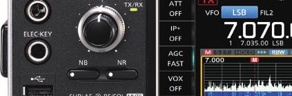
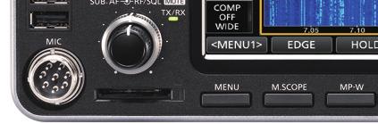
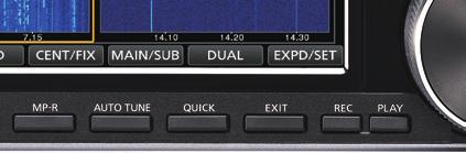
10 1 PANEL DESCRIPTION Front panel w e r t y u i q q POWER KEY POWER (p. 3-1) Turns the transceiver ON or OFF. w TRANSMIT KEY TRANSMIT (p. 3-9) Toggles between transmit and receive. e TIMER KEY TIMER Turns the Sleep Timer or Daily Timer function ON or OFF.!2 o!1!0 o The TX/RX indicator Lights green while receiving. Lights red while transmitting. r HEADPHONE JACK [PHONES] (p. 13-3) Connects to standard stereo headphones. t ELECTRONIC KEYER JACK [ELEC-KEY] (p. 13-3) Connects to a paddle to use the internal electronic keyer for the CW operations. y USB PORT [USB A] (p. 13-) Insert a USB flash drive, USB A type keyboard, RC-2 remote encoder, mouse or hub. u MICROPHONE CONNECTOR [MIC] (p. 13-3) Connects to the supplied or an optional microphone. i SD CARD SLOT [SD CARD] (p. 6-1) Accepts an SD card. The indicator next to the slot lights blue when inserted. o VOLUME CONTROL AF RF/SQL (p. 3-1) L The upper control is for the Main band, and the lower control is for the Sub band. Push to turn the Mute function ON or OFF. - The TX/RX indicator lights orange when the Mute function is ON. Adjusts the audio output level. RF GAIN/SQUELCH CONTROL AF RF/SQL (p. 3-7) Adjusts the RF gain and squelch threshold levels.!0 NOISE REDUCTION KEY NR (p. -5) Turns the Noise Reduction function ON or OFF.!1 NOISE BLANKER KEY NB (p. -5) Turns the Noise Blanker ON or OFF.!2 ANTENNA TUNER KEY TUNER (p. 7-3) Turns the antenna tuner ON or OFF, or activates MENU KEY MENU (p. -1) Displays the MENU screen.! MINI SCOPE KEY M.SCOPE (p. 5-2) Displays the Mini Scope or Spectrum Scope.!5 MEMO PAD WRITE KEY MP-W Saves the displayed contents into the Memo Pad.!6 MEMO PAD READ KEY MP-R Sequentially calls up the contents in the Memo Pad.!7 AUTO TUNE KEY AUTO TUNE (p. -) Automatically tunes the operating frequency to a received CW signal.! QUICK KEY QUICK (p. 1-7) Displays the QUICK MENU. 1-1
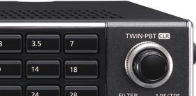
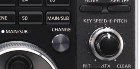
11 PANEL DESCRIPTION 1 Front panel (Continued)!9 EXIT KEY EXIT Exits a setting screen or returns to the previous VOICE MEMORY RECORD KEY REC Saves the previously received signal for the preset time period set in REC Time, using the Instant Replay function, or starts recording a QSO audio onto an SD VOICE MEMORY PLAY BACK KEY PLAY Plays back the last 5 seconds of the Instant Replay memory, or all of the Instant @9 MULTI-FUNCTION CONTROL MULTI (p. 1-6) Displays the Multi-function menu for various adjustments, or selects an SPLIT KEY SPLIT (p. -9) Turns the Split function ON or DUALWATCH KEY DUAL-W (p. 3-2) Turns the Dualwatch function ON or GENERAL COVERAGE BAND KEY GENE Selects the general coverage band. #9 # #7 #6 #5 # #3 TRANSMIT FREQUENCY CHECK KEY XFC (p. -1, -9, -10) Enables you to monitor the transmit frequency while holding it down in the Split TENSION ADJUSTER Adjusts the friction of MAIN MAIN DIAL MAIN DIAL (p. 3-) Changes the operating frequency. SPEECH/LOCK KEY SPEECH Announces the operating frequency and mode by pushing this key. Electronically locks MAIN DIAL by holding down this key for 1 second. #0 MAIN/SUB CHANGE KEY CHANGE (p. 3-2) Toggles the frequency, mode and selected memory channel between the Main and Sub band. #1 RIT/ TX CONTROL RIT/ TX (p. -1) Shifts the receive or transmit frequency up to ±9.99 khz without changing the transmit or receive frequency. #2 TX KEY TX Turns the TX function ON or OFF. #3 CLEAR KEY CLEAR Clears the RIT or TX shift frequency. # RIT KEY RIT (p. -1) Turns the Receiver Incremental Tuning (RIT) function ON or OFF. #5 KEY SPEED KEY SPEED PITCH CONTROL (p. -11) Adjusts the internal electronic CW keyer speed. CW PITCH KEY SPEED PITCH CONTROL (p. -10) Shifts the received CW audio pitch and the CW side tone pitch without changing the operating frequency. #6 MAIN/SUB ACCESS KEY MAIN/SUB (p. 3-2) Selects the Main or Sub band frequency readout. The selected band s frequency is displayed clearly whereas the non-selected band s frequency is displayed in gray. #7 AUDIO PEAK FILTER/ TWIN PEAK FILTER KEY APF/TPF (p. -12) In the CW mode, turns the Audio Peak Filter ON or OFF, and in the RTTY mode, turns the Twin Peak Filter ON or OFF. # FILTER KEY FILTER (p. -) Selects one of three IF filters. #9 TWIN PASSBAND TUNING CONTROL TWIN PBT CLR (p. -3) Adjusts the IF filter s passband width. $0 KEYPAD 1. ~ 50 Selects the operating band by pushing once, or call up other stacked frequencies by pushing the same key several times
12 1 PANEL DESCRIPTION Rear panel q w e r y u!!3!2!1!0 o i q DC POWER SOCKET [DC 13. V] Connects to 13. V DC through the DC power cable. w TUNER CONTROL SOCKET [TUNER] Accepts the control cable from an optional AH- or AH-70 automatic antenna tuner. e COOLING FAN Cools the PA unit when necessary. r GROUND TERMINAL [GND] Connects to ground to prevent electrical shocks, TVI, BCI and other problems. t ANTENNA CONNECTOR [ANT1]/[ANT2] Connects to a 50 Ω antenna. If you use the AH- or AH-70, you must connect the antenna to [ANT1]. y ALC INPUT JACK [ALC] Connects to the ALC output jack of a non-icom linear amplifier. u SEND CONTROL JACK [SEND] Connects to control transmit with non-icom external units. i EXTERNAL SPEAKER JACK A/B [EXT-SP] Accepts a ~ Ω external speaker. o USB PORT [USB 1] (Type B) Connects to a PC for remote control operations.!0 USB PORT [USB 2] (Type B) For digital data input or output.!1 EXTERNAL DISPLAY CONNECTOR [EXT-DISPLAY] Connects to an external display monitor.!2 ETHERNET CONNECTOR [LAN] Connects to a PC network through a LAN.!3 TRANSVERTER CONNECTOR [X-VERTER] Connects to an external transverter for input/output.! REFERENCE SIGNAL INPUT [REF IN] Input for a 10 MHz reference signal through the BNC connector.!5 RECEIVE ANTENA [RX ANT IN]/[RX ANT OUT] Connects to an external unit, such as preamplifier or RF filter, using BNC connectors. This is located between the transmit/receive switching circuit and receiver s RF stage.!6 CI-V REMOTE CONTROL JACK [REMOTE] Connects to a PC or other transceiver for remote control.!7 METER JACK [METER] Outputs received signal strength, transmit output power, VSWR, ALC, speech compression, Vd or Id levels for an external meter.! EXTERNAL KEYPAD JACK [EXT KEYPAD] (p. 13-) Connects to an external keypad for direct voice memory, memory keyer, RTTY memory or PSK memory transmission.!9 STRAIGHT KEY JACK [KEY] Connects to a straight key, paddle, or an external electronic keyer with 6.35 mm (¼ in) stereo ACC SOCKET [ACC1]/[ACC2] Connects to devices to control an external unit or to control the transceiver. 1-3
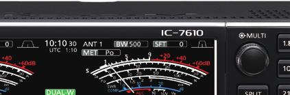
 Displays the selected antenna connector between ANT 1 and ANT 2. e METER TYPE INDICATOR (p. 3-7) Displays the selected transmit parameter type. Select between Po, SWR, ALC, COMP, Vd and Id.")
13 PANEL DESCRIPTION 1 Touch screen q w e r t y u i o!0!1 w e r t y u i q MULTI-FUNCTION KEY GROUP Displays the Multi-function keys. w ANTENNA INDICATOR (p. 7-1) Displays the selected antenna connector between ANT 1 and ANT 2. e METER TYPE INDICATOR (p. 3-7) Displays the selected transmit parameter type. Select between Po, SWR, ALC, COMP, Vd and Id. r BANDWIDTH INDICATOR (p. -3, -) Displays the passband width of the IF filter. t SHIFT FREQUENCY INDICATOR (p. -3) Displays the shift frequency of the IF filter. y NOTCH INDICATOR (p. -6) AN is displayed when the Auto Notch function is ON, and MN is displayed when the Manual Notch function is ON. u PASSBAND WIDTH INDICATOR (p. -3) Displays the passband width for twin PBT operation and the center frequency for IF shift operation. i AUDIO PEAK FILTER (APF) INDICATOR (p. -12) Displayed when the Audio Peak Filter is ON. o CLOCK READOUT (p. 9-1) Displays the time (2 types) set on the TIME SET screen.!0 USB INDICATOR (p. 6-1) Displayed while a USB flashed drive is inserted.!1 LAN INDICATOR Displayed while the transceiver and the optional RS-BA1 are connected through the LAN for remote control operation. 1-!2 BK-IN/F-BKIN INDICATOR (p. -11) Displayed while the Semi Break-in or Full Break-in function is ON.!3 NET FUNCTION INDICATOR (p. -7) Displayed when the NET function is ON while in the PSK mode.! FREQUENCY OFFSET READOUT Displays the offset value between the PSK signal and the operating frequency, while a PSK signal is received.!5 AFC FUNCTION INDICATOR Displayed while the Automatic Frequency Control (AFC) function is ON, in the PSK mode.!6 FREQUENCY READOUT (p. 3-) Displays the operating frequency. L The non-selected band s frequency readout (Main or Sub) is displayed in gray.!7 FUNCTION DISPLAY Displayed when an item that has a function display is selected. For example, the Spectrum Scope.! FUNCTION KEYS (p. 5-1) Displays the operating parameters, modes, frequencies and indicators, and so on.!9 VOX INDICATOR Displayed while the VOX function is VOICE RECORDER ICON is displayed while recording. is displayed while pausing.!2!3!!5!6!7!
 VFO is displayed when the VFO mode is selected, and the memory number is displayed when a Memory channel is selected. @2 TX STATUS INDICATOR (p.")
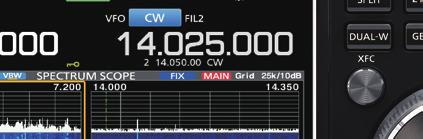
14 1 PANEL DESCRIPTION Touch screen @9 #0 #1 #2 @3 #9 # #7 #6 #5 $1 $0 #9 # #7 #6 VFO/MEMORY ICON (p. 3-1) VFO is displayed when the VFO mode is selected, and the memory number is displayed when a Memory channel is TX STATUS INDICATOR (p. 3-, 3-9) Displays the transmit status of the displayed frequency. is displayed while the displayed frequency is within the amateur band range. (Red background) is displayed while transmitting. (With a border of short dashes) is displayed when the selected frequency is outside of the amateur band frequency. (Grayed out) is displayed while the transmitter is RF GAIN INDICATOR (p. 3-7) Displayed when AF RF/SQL (outer) is set counterclockwise from the 11 o clock position. The indicator shows that the RF gain is OVF ICON (p. 3-7) OVF is displayed when an excessively strong signal is METER INDICATOR (p. 3-7) Displays the S, Id, Po, SWR, COMP, ALC and Vd MODE INDICATOR (p. 3-3) Displays the selected operating IF FILTER INDICATOR (p. -3, -) Displays the selected IF QUICK TUNING ICON (p. 3-) Displayed when the quick Tuning Step function is AUTO TUNE INDICATOR (p. -) Displays AUTOTUNE when the Auto Tuning function is ON. #0 SPLIT ICON (p. -9) Displayed when the Split function is ON. #1 DUALWATCH ICON (p. 3-2) Displayed when using Dualwatch. #2 SHIFT FREQUENCY READOUT (p. -1) Displays the shift offset for the RIT or TX functions, while these functions are ON. #3 RIT ICON (p. -1) Displayed when the RIT function is ON. # TX ICON Displayed when the TX function is ON. #5 1/ TUNING STEP INDICATOR (p. 3-5) Displayed while the 1/ Tuning Step function is ON. #6 M1~M/T1~T Displays M1 ~ M while using the Memory Keyer function is used. Displays T1 ~ T while using the Voice TX memory function. #7 MEMORY CHANNEL/VFO READOUT (p. 3-1) Displays the selected memory channel contents in the VFO mode, and displays the VFO contents in the Memory mode. # LMT ICON Displayed if the power amplifier temperature becomes extremely high and the protection function is activated after transmitting continuously for long periods of time. #9 SELECT MEMORY CHANNEL ICON Indicates that the displayed memory channel is assigned as a Select memory channel ( 1~ 3). $0 PLAY ICON Displayed while playing the recorded voice audio. $1 DIAL LOCK INDICATOR (p. 3-6) Displayed while the Lock function is ON. 1-5


15 PANEL DESCRIPTION 1 Touch screen display (Continued) DDMENU screen DDMulti-function menus Touch to turn ON or OFF Multi-function menu zopen the Multi-function menu by pushing (Multi-function control). MULTI zwhile the Multi-function menu is open, touch the desired item and rotate MULTI to adjust the value. L You can open other menus by holding down NB or NR for 1 second, or touching ATT, VOX, BK-IN or COMP in the Multi-function key group for 1 second. zopen the MENU screen by pushing MENU. Function name Status Lights blue or orange when in use L The items displayed on the menu differ, depending on the selected operating mode. Multi-function menu items SSB CW RTTY PSK RF POWER RF POWER RF POWER RF POWER MIC GAIN DIGI-SEL DIGI-SEL DIGI-SEL DIGI-SEL NOTCH NOTCH NOTCH NOTCH NOTCH WIDTH NOTCH WIDTH NOTCH WIDTH NOTCH WIDTH MONITOR MONITOR MONITOR AM FM NB NR RF POWER RF POWER LEVEL LEVEL MIC GAIN MIC GAIN DEPTH DIGI-SEL DIGI-SEL WIDTH NOTCH NOTCH NOTCH WIDTH MONITOR MONITOR ATT VOX BK-IN COMP LEVEL GAIN DELAY LEVEL ANTI VOX TBW DELAY VOICE DELAY

16 1 PANEL DESCRIPTION Touch screen display (Continued) DDMulti-function key group Touch to turn ON or OFF, or to set Multi-function key group Multi-function key group items SSB CW RTTY PSK AM FM ANT P.AMP ATT IP+ AGC VOX BK-IN COMP TONE ztouch a key to turn the function ON or OFF. ztouching ATT, VOX, BK-IN or COMP for 1 second opens the ATT menu, VOX menu, BK-IN menu or COMP menu. L See Multi-function menus on the previous page for details. DDQUICK MENU zopen the QUICK MENU by pushing QUICK. 1-7

 ~ (T) MEMORY NAME DDKeyboard types You can select the Full Keyboard or Tenkey by pushing QUICK")

17 PANEL DESCRIPTION 1 Keyboard entering and editing You can enter and edit the items on the following screens. LUsable characters, symbols, and the amount of characters that can be entered differs, depending on the editing item. MY CALL FILE NAME NETWORK NAME NETWORK RADIO NAME NETWORK USER1 ID NETWORK USER2 ID NETWORK USER 1 PASSWORD NETWORK USER 2 PASSWORD NTP SERVER ADDRESS CLOCK2 NAME KEYER MEMORY PSK MEMORY RTTY MEMORY VOICE TX RECORD (T1) ~ (T) MEMORY NAME DDKeyboard types You can select the Full Keyboard or Tenkey by pushing QUICK while displaying an entry mode screen. DDEntering and editing Moves the cursor backward Enters an uppercase letter Moves the cursor forward Clears the entered character Selects the character type Saves the entry Selects alphabet mode or number mode Enters a space Cancels entry and returns to the previous screen Alphabet mode Number mode Symbol mode 1-


![7. Touch [s], [p], [o], and then [t].. Touch [SPACE] to enter a space. 9.](/docs-images/74/71445305/images/18-2.jpg "Touch [ab]. The CHARACTER TYPE screen is displayed. 3. Touch Edit Name.")

![Touch [12].. Touch [ ], and then touch [D].](/docs-images/74/71445305/images/18-4.jpg "L Touching [ ] changes between uppercase and lowercase letter. 11. Touch [1].")
18 1 PANEL DESCRIPTION Keypad entering and editing (Continued) DDEntering and editing example Entering DX spot 1 in the Memory channel 2 1. Display the MEMORY screen. MENU» MEMORY 2. Touch the memory channel 2 for 1 second. The MEMORY MENU screen is displayed. 7. Touch [s], [p], [o], and then [t].. Touch [SPACE] to enter a space. 9. Touch [ab]. The CHARACTER TYPE screen is displayed. 3. Touch Edit Name. The MEMORY NAME screen is displayed. You can also display the MEMORY MENU screen by touching this key. 10. Touch [12].. Touch [ ], and then touch [D]. L Touching [ ] changes between uppercase and lowercase letter. 11. Touch [1]. 12. Touch [ENT] to save the entry. 5. Touch [ ] again, and then touch [X]. 6. Touch [SPACE] to enter a space. Returns to the previous screen. 1-9
19 INSTALLATION AND CONNECTIONS 2 Using the desktop stands Heat dissipation The transceiver has legs for desktop use. zpull-out the legs on both sides until they lock in place. NOTE: DO NOT hold the stand, dials and controls when you carry the transceiver. This may damage them. Selecting a location Select a location for the transceiver that allows adequate air circulation, free from extreme heat, cold or vibrations, and other electromagnetic sources. Never place the transceiver in areas such as: Temperatures below 0 C (+32 F) or above +50 C (+122 F). An unstable place that slopes or vibrates. In direct sunlight. High humidity and temperature environments. Dusty environments. Noisy environments. NEVER install the transceiver in a place without adequate ventilation. Heat dissipation may be reduced, and the transceiver may be damaged. DO NOT place the transceiver against walls or put anything on top of the transceiver. This may block airflow and overheat the transceiver. DO NOT touch the rear panel after transmitting continuously for long periods of time. The panel may become hot. Grounding Connecting an external DC power supply Be sure that the power supply power is OFF before connecting the DC power cable. We recommend using Icom s optional PS-126 (13. V DC/25 A) power supply. AC Outlet AC cable + PS-126 Non-Icom DC power supply 13. V DC/23 A or more _ DC power cable w q To prevent electrical shock, television interference (TVI), broadcast interference (BCI) and other problems, ground the transceiver using the ground terminal [GND] on the rear panel. For best results, connect a heavy gauge wire or strap to a long ground rod. Make the distance between the [GND] terminal and ground as short as possible. RWARNING! NEVER connect the [GND] terminal to a gas or electric pipe, since the connection could cause an explosion or electric shock. L When using a non-icom DC power supply, you need: 13. V DC (Capacity: At least 23 A) A power supply with an over current protective line and low voltage fluctuation or ripple. To disconnect, firmly push down the locking tab and then pull the connector out of the socket. CAUTION: DO NOT touch the rear panel of the transceiver after transmitting continuously for long periods of time. It can become very hot Red Fuse Black GND 2-1
20 2 INSTALLATION AND CONNECTIONS Connecting the antenna tuner The AH- matches the IC-7610 to the optional AH-2b or to a long wire antenna more than 7 m/23 ft long (usable between 3.5 and 50 MHz). L See the AH- instruction manual for installation and connection details. L See the Advanced Manual for connecting the optional AH-70 automatic antenna tuner. NOTE: Before connecting, be sure to turn OFF the transceiver. While the AH- is connected, the IC-7610ʼs internal antenna tuner is deactivated. HF band long wire antenna AH- Coaxial cable (50 Ω) [TUNER] [ANT 1] GND GND Connecting a Transverter Connect your transverter unit as described below. L You may need to connect to [ALC], depending on the transverter. VHF/UHF band antenna Transverter RX TRV RX RF IN/OUT Coaxial cable (50 Ω) ANT TX TRV TX [SEND] [X-VERTER] GND [SEND] GND Set the Transverter Function item to ON to use the transverter operating mode. You can also use the transverter operating mode by connecting a DC voltage to [ACC 2 (6: TRV)]. MENU» SET > Function > Transverter Function LYou cannot select the antenna or use the internal tuner while using the Transverter function. Set the offset frequency for the transverter operation. MENU» SET > Function > Transverter Offset 2-2
21 INSTALLATION AND CONNECTIONS 2 Linear amplifier connections DDConnecting the IC-PW1/IC-PW1EURO See the illustration below to connect the optional IC-PW1 or IC-PW1EURO hf/50 mhz all band 1 kw linear amplifier. Refer to the amplifier s instruction manual for operation. To an antenna [ACC 1] [REMOTE] EXCITER 1 1 & 2 ACC cable To an AC outlet Non-European versions: 100~120/200~20 V European version: 230 V Remote control cable [INPUT 1] GND Coaxial cable (50 Ω) [REMOTE] [ACC 2] [ANT 1] R WARNING! When using a linear amplifier such as the IC-PW1 or IC-PW1EURO, set the RF POWER in the Multi-function menu to keep the ALC meter in the red zone. LSee page 3- for details on the RF POWER settings. LSee page 3-9 for details on the ALC zone settings. DDConnecting a non-icom linear amplifier See the illustration below to connect a non-icom linear amplifier. L We recommend that you use a linear amplifier with a specified input power of 100 watts or more. If you use an amplifier with a specified drive level of less than 100 watts, adjust the IC-7610 s output power to the specified level before transmitting. Otherwise the linear amplifier may be damaged. To an antenna Non-Icom linear amplifier RF OUT RF IN ALC SEND Coaxial cable (50 Ω) [ANT1] or [ANT2] GND GND GND [ALC] [SEND] R WARNING! The maximum signal level of the [SEND] jack is 16 V/0.5 A DC, and 250 V/200 ma with the MOSFET setting (p. 13-2). Use an external unit if your non-icom linear amplifier requires a control voltage and/or current greater than specified. The ALC input level must be in the range 0 to V. The transceiver does not accept a positive voltage. Non-matched ALC and RF power settings could overheat or damage the linear amplifier. 2-3

22 3 BASIC OPERATION When first applying power Before turning ON your transceiver for the first time, make sure all connections are correctly made. After all connections are made, set the dials to the positions described below. q w e t y r q MAIN AF RF/SQL (inner): Fully counterclockwise w MAIN AF RF/SQL (outer): 12 o clock e SUB AF RF/SQL (inner): Fully counterclockwise r SUB AF RF/SQL (outer): 12 o clock t KEY SPEED y KEY SPEED PITCH (inner): Fully counterclockwise PITCH (outer): 12 o clock TIP: When you turn OFF the transceiver, it saves the current settings. Therefore, when you turn ON the transceiver again, it starts with the same settings. Turning power ON or OFF Adjusting the volume level zto turn ON the transceiver, push POWER. zto turn OFF the transceiver, hold down POWER for 2 seconds until POWER OFF... is displayed. Rotate AF RF/SQL (inner) to adjust the volume level. Selecting the VFO and Memory modes VFO mode You can set a frequency by rotating MAIN DIAL. L Using the VFO mode may be easier for the first initial operation. Memory mode You can recall a frequency that you have memorized on the MEMORY list. 3. Touch [VFO] or [Memory] to select the mode. Selecting the VFO mode or Memory mode 1. Push QUICK. The QUICK MENU screen is displayed. 2. Touch VFO/MEMORY. VFO indicator VFO mode screen Memory channel number Memory mode screen 3-1. Push EXIT to close the VFO/MEMORY screen.


23 BASIC OPERATION 3 Selecting the Main and Sub bands The IC-7610 has 2 identical receivers, Main and Sub. The Main band is displayed on the left side of the screen, and the Sub band is displayed on the right side. Some functions can only be applied to the selected band, and you can transmit on only the Main band (except in Split Frequency operation). To select the Main band or Sub band, touch the frequency readout. The selected band s frequency readout is displayed clearly, and the frequency of the non-selected band is grayed. The selected band s indicator lights as described below. Example: When the Sub band is selected, the MAIN/SUB indicator lights on the Sub band side. Main The Main band is selected. The Sub band is selected. Not lit MAIN/SUB Sub NOTE: The Sub band readout is activated during Split operation or Dualwatch operation. See page -9 for details on Split operation. See the right column for details on Dualwatch operation. L You can also push MAIN/SUB to select the Main band or Sub band. Lit DDSwitching the Main band and Sub band You can switch the Main band and Sub band settings, such as the operating frequency, mode, and so on. Push CHANGE. The Main and Sub band settings are switched. Dualwatch operation Dualwatch simultaneously monitors two frequencies. The IC-7610 has 2 independent receiver circuits, the Main and Sub bands, so that you can use Dualwatch with no compromises, even on different bands and modes. DUAL-W MAIN/SUB CHANGE MAIN DIAL DDUsing the Dualwatch operation 1. Push DUAL-W briefly to start the Dualwatch operation. DUAL-W is displayed. L To equalize the Sub band frequency and mode to those of the Main band, hold down DUAL-W for 1 second. This Quick Dualwatch function can be turned OFF in the Others set screen. (p. -3) 2. Touch the frequency readout of the band you want to set the frequency. 3. Rotate MAIN DIAL to set the frequency Displayed

![L In the SSB, AM or FM mode, the [DATA] key is displayed. The 1 MHz band frequency is displayed. D DSelecting the operating band on the screen (Example: Selecting 21 MHz in the Main band.) 1.](/docs-images/74/71445305/images/24-1.jpg "Touch the MHz digits to display the BAND STACKING REGISTER screen. 2. Touch [21].")
![Operating mode selection list Mode key Operating mode [SSB] LSB USB [CW] CW CW-R [RTTY] RTTY RTTY-R [PSK] PSK PSK-R [AM] AM [FM] FM LSB LSB-D [DATA] USB USB-D AM AM-D FM FM-D Selecting the Data mode](/docs-images/74/71445305/images/24-2.jpg "You can operate in the data mode in the SSB, AM and FM modes. The Data mode enables you to operate these modes without input from the microphone, even if the microphone is connected.")
24 3 BASIC OPERATION Selecting the operating band D DSelecting the operating band on the keypad (Example: Selecting 1 MHz in the Main band.) 1. Touch the Main band s frequency readout. 2. Push 1 on the band keypad. Keypad Selecting the operating mode You can select the SSB, CW, RTTY, PSK, AM, or FM modes. 1. Touch the mode icon. 2. Touch the mode key. L In the SSB, AM or FM mode, the [DATA] key is displayed. The 1 MHz band frequency is displayed. D DSelecting the operating band on the screen (Example: Selecting 21 MHz in the Main band.) 1. Touch the MHz digits to display the BAND STACKING REGISTER screen. 2. Touch [21]. Operating mode selection list Mode key Operating mode [SSB] LSB USB [CW] CW CW-R [RTTY] RTTY RTTY-R [PSK] PSK PSK-R [AM] AM [FM] FM LSB LSB-D [DATA] USB USB-D AM AM-D FM FM-D Selecting the Data mode You can operate in the data mode in the SSB, AM and FM modes. The Data mode enables you to operate these modes without input from the microphone, even if the microphone is connected. L When the data mode is selected, you can select the connector(s) modulation signal. (p. -6) MENU» SET > Connectors > DATA1 MOD ~ DATA3 MOD (Example: USB-D mode) 1. While the USB mode is selected, touch the mode icon. 2. Touch [DATA]. [USB-D1] is displayed. About the Band Stacking Register: The band stacking register provides 3 memories for each band key to store frequencies and operating modes. Sequentially select the registered memories: zrepeatedly push a band key on the keypad. zrepeatedly touching a band key on the BAND STACKING REGISTER screen for 1 second. 3-3 TIP: See the Advanced Manual for details on using the Data mode.
 is displayed when you set a")

: AM (TS ON): FM (TS ON): 10 Hz 1 khz 10 khz Touch the khz digits to turn the Tuning Step function ON or")

 The tuning step is set and returns to the previous screen. The Tuning Step function is ON.")

25 BASIC OPERATION 3 Setting the frequency DDUsing the Main Dial 1. Select the operating band. (Example: 21 MHz) 2. Rotate MAIN DIAL. L is displayed when you set an amateur radio frequency, and ( TX with a border of short dashes) is displayed when you set a frequency outside the Ham band, or outside your set Band Edges. DDSetting the Tuning Step function You can set MAIN DIAL s tuning step for each operating band. This is convenient to change the operating frequency faster or slower. The following steps are set as default. SSB/CW/RTTY/PSK (TS OFF): AM (TS ON): FM (TS ON): 10 Hz 1 khz 10 khz Touch the khz digits to turn the Tuning Step function ON or OFF. L The Tuning Step function s icon is displayed above the 1 khz digit when the function is ON. DDChanging the Tuning Step When the Tuning Step function is ON, you can change the tuning steps for each operating mode. 1. Select the desired operating mode. 2. Touch the khz digit for 1 second. 3. Touch the tuning step. (Example: 0.1 k) The tuning step is set and returns to the previous screen. The Tuning Step function is ON. D DUsing the 1 Hz step Fine Tuning function You can use the minimum tuning step of 1 Hz for fine tuning in the SSB, CW and RTTY modes as the default. Touch the Hz digits for 1 second to turn the Fine Tuning function ON or OFF. The 1 Hz digit is displayed. L When using the [UP]/[DN] keys on the microphone, the frequency changes in 50 Hz steps with the Fine Tuning function ON or OFF The Tuning Step function is ON. 3-
26 3 BASIC OPERATION Setting the frequency (Continued) DDUsing the 1/ Tuning function With the Tuning Function OFF, turn ON the 1 Tuning function to reduce the tuning speed to 1 of the normal speed, for finer tuning in the SSB-D, CW, RTTY and PSK modes. 1. Push MENU. 2. Touch [1/]. DDDirectly entering a frequency You can directly enter a frequency using the keypad. Entering the operating frequency 1. Touch the MHz digits. (Example: 1) 2. Touch [F-INP]. Opens the F-INP screen. 3. Push EXIT to close the MENU screen. 1/ Tuning function ON 3. Start by entering the MHz digits. LTo clear the entry, touch [CE]. L To clear the entry and return to the previous screen, push EXIT.. Touch [ENT] to save the entered frequency. Closes the F-INP screen. DDUsing the Auto Tuning Step function The tuning step automatically changes, depending on the rotating speed of MAIN DIAL. L You can change the Auto Tuning Step function settings in the following menu. (p. -) MENU» SET > Function > MAIN DIAL Auto TS L If you touch [ENT] when the digits under 100 khz are not entered, 0 will be automatically entered into the digits that are blank. Entry examples MHz: [1], [], [ ( )], [0], [2], [5], [ENT] MHz: [1], [], [ ( )], [0], [7], [2], [5], [ENT] 730 khz: [0], [ ( )], [7], [3], [ENT] MHz: [5], [ ( )], [1], [ENT] MHz: [7], [ENT] Changing from MHz to MHz: [ ( )], [2], [], [5], [ENT] 3-5
]. L Enter an offset between 9.999 MHz and +9.999 MHz (1 khz steps).")
![Touch for -Split [SPLIT] or [-SPLIT] is displayed Entry examples 10 khz: [1], [0], [SPLIT] 1.025 MHz: [ ( )], [1], [0], [2], [5], [ SPLIT] 2.](/docs-images/74/71445305/images/27-2.jpg "To save the entry, touch [SPLIT] or [ SPLIT]. Closes the F-INP screen, and the Split function is automatically turned ON. The Split function is ON.")
![Dial Lock function Shifted by the offset amount. Entering a Memory channel 1. Push QUICK, and touch VFO/MEMORY. 2. Touch [MEMORY] to select the Memory mode. 3.](/docs-images/74/71445305/images/27-3.jpg "Touch the MHz digits.. Touch [F-INP]. Memory mode 5. Enter a Memory channel number between 1 and 99.")
![(Example: Memory channel 5) L If you want to set a Program Channel number (P1 or P2), enter 100 for P1, and 101 for P2. 6. Touch [MEMO] to save the entered channel.](/docs-images/74/71445305/images/27-6.jpg "Closes the F-INP screen. 1 2 3 5 6 7 9 10 11 12 13 1 15 16 17 1 19 20 21 The Dial Lock function prevents frequency changes caused by accidently rotating MAIN DIAL.")
27 BASIC OPERATION 3 Setting the frequency (Continued) Entering a Split Frequency Offset 1. On the F-INP screen, enter the Split Frequency Offset. LTo enter a minus shift direction, touch [ ( )]. L Enter an offset between MHz and MHz (1 khz steps). Touch for -Split [SPLIT] or [-SPLIT] is displayed Entry examples 10 khz: [1], [0], [SPLIT] MHz: [ ( )], [1], [0], [2], [5], [ SPLIT] 2. To save the entry, touch [SPLIT] or [ SPLIT]. Closes the F-INP screen, and the Split function is automatically turned ON. The Split function is ON. Dial Lock function Shifted by the offset amount. Entering a Memory channel 1. Push QUICK, and touch VFO/MEMORY. 2. Touch [MEMORY] to select the Memory mode. 3. Touch the MHz digits.. Touch [F-INP]. Memory mode 5. Enter a Memory channel number between 1 and 99. (Example: Memory channel 5) L If you want to set a Program Channel number (P1 or P2), enter 100 for P1, and 101 for P2. 6. Touch [MEMO] to save the entered channel. Closes the F-INP screen The Dial Lock function prevents frequency changes caused by accidently rotating MAIN DIAL. LThis function electronically locks the dial. Hold down SPEECH for 1 second to turn the Dial Lock function ON or OFF. is displayed while the function is ON. During Split Frequency operation, the Split Lock function may be turned ON. (p. -10) MENU» SET > Function > Lock Function Hold down 3-6
 adjusts the RF gain, and rotating to the right adjusts the squelch level, as described below.")

28 3 BASIC OPERATION RF gain and SQL level Meter display Rotate AF RF/SQL (outer) to adjust the RF gain and SQL level. By default, rotating to the left (when set to the 12 o clock position) adjusts the RF gain, and rotating to the right adjusts the squelch level, as described below. DDSelecting the Meter readout Select one of the 6 different transmit parameters (Po, SWR, ALC, COMP, Vd and Id) to display during transmit. Touch the meter to display one of the meters. The selected meter s icon is displayed. Squelch is open RF gain adjustable range is displayed Minimum RF gain Noise squelch (FM mode) Maximum RF gain S-meter squelch adjustable range Maximum S-meter squelch Signal strength RF gain You can adjust the receive sensitivity. If a strong interfering signal is received, rotate AF RF/SQL (outer) counterclockwise to reduce the RF gain. L RFG is displayed to indicate that the gain is reduced. L If a strong signal is received and OVF (Overflow) appears, reduce the RF gain until OVF disappears. Squelch (SQL) level There are 2 types of squelch, depending on the operating mode. Noise squelch Rotate the AF RF/SQL (outer) until the noise just disappears and the TX/RX indicator goes OFF. S-meter squelch The S-meter squelch disables the audio output from the speaker or headphones when the received signal is weaker than the specified S-meter squelch level. Rotate the AF RF/SQL clockwise from the 12 o clock position to increase the S-meter threshold level. L You can change the AF RF/SQL (outer) control type in RF/SQL Control. (p. -3) MENU» SET > Function > RF/SQL Control Id Power level SWR Compression level ALC level DDAbout the Multi-function meter S: Displays the receiving signal strength level. Po: Displays the relative RF output power. SWR: Displays the SWR of the antenna at the selected frequency. ALC: Displays the ALC level. When the meter movement shows the input signal level exceeds the allowed level, the ALC limits the RF power to suppress signal distortion. In such cases, decrease the microphone gain level. COMP: Displays the compression level when the speech compressor is used. V d: Displays the drain voltage of the final amplifier MOS-FETs. Id: Displays the drain current of the final amplifier MOS-FETs. TEMP: Displays the temperature of the final amplifier MOS-FETs. Vd 3-7

![zwhile the Multi-function meter is displayed, touch [P-HOLD] to turn ON the Peak Level Hold function. P-HOLD is displayed on the Multi-function meter window title. L To turn OFF, push EXIT.](/docs-images/74/71445305/images/29-1.jpg "Adjusting the transmit output power Displayed when Peak Hold function is ON.")
29 BASIC OPERATION 3 Meter display (Continued) DDDisplaying the Multi-function meter You can simultaneously display all the parameters. L The TEMP meter is also displayed on the Multi-function meter. ztouch the meter for 1 second to display the Multi-function meter. L To close the Multi-function meter, touch the meter for 1 second again. zwhile the Multi-function meter is displayed, touch [P-HOLD] to turn ON the Peak Level Hold function. P-HOLD is displayed on the Multi-function meter window title. L To turn OFF, push EXIT. Adjusting the transmit output power Displayed when Peak Hold function is ON. Before transmitting, monitor your selected operating frequency to make sure you do not cause interference to other stations on the same frequency. It is good amateur practice to listen first, and then, even if nothing is heard, ask if the frequency is in use once or twice, before you start operating. DDAdjusting the transmit output power 1. Set the operating mode to SSB, CW, RTTY, PSK or FM. (p. 3-3) 2. Touch the meter several times to display the Po meter. is displayed. 3. Push MULTI to open the Multi-function menu.. Hold down [PTT] (or push TRANSMIT ). The Po meter level changes according to your voice level in the SSB mode. The TX/RX indicator lights red and is displayed. L Tune the antenna before you view the power meter level on the meter. If the antenna is not tuned properly, the meter will not reflect the power level. 5. Touch RF POWER. 6. Rotate MULTI to adjust the transmit output power to between 0 and 100%. The Po meter displays the RF output power in a percentage. It becomes the S-meter while receiving. 7. Release [PTT] (or push TRANSMIT again). Returns to receive
 to transmit. The TX/RX indicator lights red and is displayed while transmitting. 2. Release [PTT] (or push TRANSMIT again).")
30 3 BASIC OPERATION Adjusting the microphone gain Adjust the microphone gain as described below. 1. Set the operating mode to SSB, AM or FM. (p. 3-2) 2. Push MULTI to display the Multi-function menu. 3. Touch MIC GAIN. Basic transmission 1. Hold down [PTT] (or push TRANSMIT ) to transmit. The TX/RX indicator lights red and is displayed while transmitting. 2. Release [PTT] (or push TRANSMIT again). Returns to receive.. Hold down [PTT] on the microphone. The TX/RX indicator lights red and is displayed. 5. Rotate MULTI to adjust the microphone gain. 6. Release [PTT]. Returns to receive LLInformatio In the SSB mode, touch the TX meter to select the ALC meter, and adjust until the meter reading swings between 30 to 50% of the ALC scale, when speaking into the microphone at your normal voice level. In the AM or FM mode, check the audio clarity with another station, or use the Monitor function (p. -7). 3-9


![broadcasting station. Touch [ATT] to sequentially set the Attenuator up to 1 db in 6 db steps. You can also set the Attenuator in 3 db steps: 1. Touch [ATT] for 1 second to open the ATT menu.](/docs-images/74/71445305/images/31-3.jpg "RIT function The RIT (Receive Increment Tuning) function compensates for differences in the transmit frequencies of other stations. The function shifts your Main bandʼs receive frequency up to ±9.")
31 RECEIVING AND TRANSMITTING Preamplifiers The preamps amplify received signals in the receiver front end to improve the signal-to-noise ratio and sensitivity. A preamp is used when the received signals are weak. LEach band memorizes the previously used Preamplifier setting. Touch [P.AMP]. L Each touch sequentially selects P.AMP 1, P.AMP 2, and P.AMP OFF. P.AMP 1 P.AMP 2 Wide dynamic range preamplifier. It is most effective for the HF low bands. Gain is approximately 12 db. High-gain preamplifier. It is most effective for the higher bands. Gain is approximately 20 db. NOTE: When you use the preamp while receiving strong signals, the receiving signal may be distorted. In such case, turn OFF the preamp. While the Digital Selector is ON, P.AMP OFF is fixed, and you cannot select P.AMP 1 or P.AMP 2. Attenuator The Attenuator prevents a signal from becoming distorted when a very strong signal is being received near your operating frequency, or when a very strong electric field, such as from a broadcasting station. Touch [ATT] to sequentially set the Attenuator up to 1 db in 6 db steps. You can also set the Attenuator in 3 db steps: 1. Touch [ATT] for 1 second to open the ATT menu. RIT function The RIT (Receive Increment Tuning) function compensates for differences in the transmit frequencies of other stations. The function shifts your Main bandʼs receive frequency up to ±9.99 khz without shifting your transmit frequency. 1. Push RIT to turn ON the RIT function. L While using the Fine Tuning function (p. 3-), the RIT frequency is displayed in digits, instead of 3. RIT frequency 2. Rotate RIT/ TX to set the RIT frequency to match the transmitting station s frequency. L You can reset the RIT frequency to 0.00 by holding down CLEAR for 1 second. L You can add the frequency shift to your operating frequency by holding down RIT for 1 second. 3. When you have finished communicating, push RIT to turn the RIT function OFF. RIT DDUsing the RIT Monitor function When the RIT function is ON, you can monitor your operating frequency while holding down XFC. LWhile monitoring: The RIT function is temporarily OFF. The Noise Reduction, Notch filter and Twin PBT settings are temporarily OFF XFC Displayed 2. Rotate MULTI to adjust the attenuator level of up to 5 db. -1
 2.")
![Touch [AGC] to sequentially select FAST, MID or SLOW. LFAST is fixed in the FM mode. DDSetting the AGC time constant You can set the preset AGC time constant. 1. Select the operating mode.](/docs-images/74/71445305/images/32-1.jpg "(Example: SSB) 2. Touch [AGC] for 1 second. Opens the AGC screen. 3. Touch FAST, MID or SLOW.. Rotate MAIN DIAL to set the time constant.")
![L You can reset to the default settings by touching [DEF] for 1 second. 5. To close the AGC screen, push EXIT.](/docs-images/74/71445305/images/32-2.jpg "Selectable AGC Time constant (unit: seconds) Mode Default Adjustable time constant LSB USB CW RTTY PSK 0.3 (FAST) OFF, 0.1, 0.2, 0.3, 0.5, 0., 1.2, 2.0 (MID) 1.6, 2.0, 2.5, 3.0,.0, 5.0 or 6.0 6.")
32 RECEIVING AND TRANSMITTING AGC function control The AGC (Automatic Gain Control) controls receiver gain to produce a constant audio output level, even when the received signal strength varies greatly. D DSelecting the AGC time constant preset value The transceiver has FAST, MID and SLOW preset AGC settings for all modes, except for the FM mode. 1. Select the operating mode. (Example: SSB) 2. Touch [AGC] to sequentially select FAST, MID or SLOW. LFAST is fixed in the FM mode. DDSetting the AGC time constant You can set the preset AGC time constant. 1. Select the operating mode. (Example: SSB) 2. Touch [AGC] for 1 second. Opens the AGC screen. 3. Touch FAST, MID or SLOW.. Rotate MAIN DIAL to set the time constant. L You can reset to the default settings by touching [DEF] for 1 second. 5. To close the AGC screen, push EXIT. Selectable AGC Time constant (unit: seconds) Mode Default Adjustable time constant LSB USB CW RTTY PSK 0.3 (FAST) OFF, 0.1, 0.2, 0.3, 0.5, 0., 1.2, 2.0 (MID) 1.6, 2.0, 2.5, 3.0,.0, 5.0 or (SLOW) 0.1 (FAST) OFF, 0.1, 0.2, 0.3, 0.5, 0., 1.2, 0.5 (MID) 1.6, 2.0, 2.5, 3.0,.0, 5.0 or (SLOW) 3.0 (FAST) OFF, 0.3, 0.5, 0., 1.2, 1.6, 2.0, AM 5.0 (MID) 2.5, 3.0,.0, 5.0, 6.0, 7.0 or (SLOW) FM 0.1 (FAST) Fixed NOTE: When you are receiving weak signals, and a strong signal is momentarily received, the AGC function quickly reduces the receiver gain. When that signal disappears, the transceiver may not receive the weak signal because of the AGC action. In that case, select FAST, or touch [AGC] for 1 second to open the AGC screen, and then select OFF. -2
 and outer (PBT2) in the opposite direction from each other.")
33 RECEIVING AND TRANSMITTING Using the Twin PBT SSB, CW, RTTY, PSK and AM modes To reject interference, the Twin PBT (Passband Tuning) narrows the IF passband width by electronically shifting the IF frequency slightly above or below the IF center frequency. The IC-7610 uses DSP for the PBT function. 1. Rotate TWIN PBT CLR inner (PBT1) and outer (PBT2) in the opposite direction from each other. LLInformatio Match both the TWIN PBT CLR (inner) (PBT1) and outer (PBT2) filters before operating the Twin PBT. Rejects interference of both higher and lower passbands. If you rotate the control too much, the received audio may not be heard because the passband width is too narrow. Displays the passband width and shift value. Hold down TWIN PBT CLR for 1 second to clear the PBT setting. The PBT is adjustable in 50 Hz steps in the SSB, CW, and RTTY modes, and 200 Hz in the AM mode. In this case, the center shift value changes in 25 Hz steps in the SSB, CW, and RTTY modes, and 100 Hz in the AM mode. Rotating both the inner and outer controls together to the same position shifts the IF left or right. 2. Hold down FILTER for 1 second to display the current passband width and shift frequency. Opens the FILTER screen. 3. To close the FILTER screen, push EXIT. NOTE: While rotating TWIN PBT CLR, you may hear noise. This comes from the DSP unit and does not indicate an equipment malfunction. PBT is OFF PBT2 Cutting the lower passband PBT2 When rotating TWIN PBT CLR PBT1 PBT2 Filter width SFT: Shift value IF center frequency Shifting value Selected IF filter Cutting both higher and lower passbands PBT2 TWIN PBT CLR FILTER Passband width (Duplicated with PB1 and PB2) The FILTER screen when rotating TWIN PBT CLR Passband center frequency BW: Passband width PBT1 PBT1 Passband PBT1 Passband IF center frequency Interference Desired signal Interference Desired signal Interference -3
, FIL 2 (mid) or FIL 3 (narrow). 1. Select the operating mode. (Example: USB) 2. Hold down FILTER for 1 second. Opens the FILTER screen. 3. Touch FIL 1 (wide), FIL 2 (mid) or FIL 3 (narrow).")
34 RECEIVING AND TRANSMITTING Selecting the IF filter The transceiver has 3 IF filter passband widths for each mode, and you can select them on the FILTER screen. You can set the IF filter to FIL 1 (wide), FIL 2 (mid) or FIL 3 (narrow). 1. Select the operating mode. (Example: USB) 2. Hold down FILTER for 1 second. Opens the FILTER screen. 3. Touch FIL 1 (wide), FIL 2 (mid) or FIL 3 (narrow).. Touch [BW]. Selects the passband width mode. 5. Rotate MAIN DIAL to select the passband width. L You cannot change the passband width in the FM or FM-D mode. L When you change the passband width, the Twin PBT setting value is reset to the center position. Displayed when the selected band width is 500 Hz or narrower, in the SSB or CW mode. Mode IF filter Selectable range (steps) SSB FIL 1 (3.0 khz) 50 Hz to 500 Hz (50 Hz)/ FIL 2 (2. khz) 600 Hz to 3.6 khz (100 Hz) FIL 3 (1. khz) SSB-D FIL 1 (1.2 khz) 50 Hz to 500 Hz (50 Hz)/ CW FIL 2 (500 Hz) 600 Hz to 3.6 khz (100 Hz) PSK FIL 3 (250 Hz) RTTY FIL 1 (2. khz) 50 Hz to 500 Hz (50 Hz) FIL 2 (500 Hz) 600 Hz to 2.7 khz (100 Hz) FIL 3 (250 Hz) FIL 1 (9.0 khz) AM FIL 2 (6.0 khz) AM-D FIL 3 (3.0 khz) 200 Hz to 10.0 khz (200 Hz) FIL 1 (15 khz) FM FIL 2 (10 khz) FM-D FIL 3 (7.0 khz) Fixed Selecting the IF filter shape You can independently set the DSP filter shape to soft or sharp for each operating mode. 1. Set the operating mode to SSB or CW. (Example: USB) 2. Hold down FILTER for 1 second. Opens the FILTER screen. 3. Select FIL1 (wide), FIL2 (mid) or FIL3 (narrow).. Touch [SHARP] or [SOFT]. Touch for 1 second to reset to default 6. Touch [BW]. Cancels the passband width mode. 7. Repeat steps 3 to 5 to set the passband width for other modes except for the FM and FM-D modes.. To close the FILTER screen, push EXIT. TIP: When you set the IF filter to FIL2 or FIL3 in the FM mode, the transceiver will transmit in the FM narrow mode. 5. To close the FILTER screen, push EXIT. SHARP This selection is to emphasize the passband width of the filter. The filter has an almost ideal shape factor. Signals of the out of passband are extremely filtered out and it gives you better audio quality. SOFT The filter shoulders are roundly formed as in analog filters. This decreases noise components in the high and low frequencies of the filter passband and increases the S/N of the target signal. These characteristics play an effective role in picking up very weak signals in the 50 MHz band, for example. The shape factor is kept, and the sharpness of the bandpass is excellent. -


35 RECEIVING AND TRANSMITTING Noise Blanker The Noise blanker eliminates pulse-type noise such as the noise from car ignitions. The Noise blanker cannot be used in the FM mode. Push NB to turn the Noise Blanker ON or OFF. The Noise Blanker indicator on NB lights. The indicator lights. NOTE: When using the Noise Blanker, received signals may be distorted if they are excessively strong, or the noise is other than a pulse type. In that case, turn OFF the Noise Blanker, or shallow the DEPTH on the NB menu. See the instruction below for details. DDAdjusting the NB level and time To deal with various types of noise, you can adjust the attenuation level and the blanking depth and width in the NB menu. 1. Hold down NB for 1 second. Turns ON the Noise Blanker and opens the NB menu. 2. Touch the adjusting item. 3. Rotate MULTI to adjust the item. (Example: ). Push MULTI to set and close the NB menu. LEVEL (Default: 50%) Adjust the level where the Noise Blanker activates between 0 and 100%. DEPTH (Default: ) Adjust the noise attenuation depth between 1 and 10. WIDTH (Default: 50) Adjust the blanking duration time between 1 and 100. Noise Reduction The Noise Reduction reduces random noise components and enhances signal audio. Push NR to turn the Noise Reduction ON or OFF. The Noise Reduction indicator on NR lights. DDAdjusting the Noise Reduction level Adjust the Noise Reduction level to where noise is reduced but the received signal is not distorted. 1. Hold down NR for 1 second. Turns ON the Noise Reduction and opens the NR menu. 2. Rotate MULTI to adjust the Noise Reduction level to between 0 and 15. L Adjust to a higher level to increase the reduction level, and to a lower level to decrease it. Noise Reduction OFF NR level 0 Noise components The indicator lights. 3. Push EXIT to close the NR menu. Noise Reduction ON NR level Desired signal (CW)


36 RECEIVING AND TRANSMITTING Digital Selector You can manually adjust the center frequency of the automatic preselector using the Digital Selector function. The automatic preselector adds selectivity ahead of the 1st mixer. This reduces intermodulation distortion from nearby strong signals. The automatic preselector tracks the frequency tuning by changing its resonant frequency in discrete steps. The Digital selector is used within the ham band, except for the 50 MHz band. DDTurning ON the Digital Selector function 1. Push MENU to open the MENU screen. 2. Touch [DIGI-SEL] to turn ON the Digital Selector function ON. LTouching [DIGI-SEL] to turn the function ON or OFF. Notch Filter The IC-7610 has Auto Notch and Manual Notch functions. Auto Notch can be used in the SSB, AM and FM modes, and Manual Notch can be used in the SSB, CW, RTTY, PSK, and AM modes. DDSelecting the Notch function type 1. Push MENU. 2. Touch [NOTCH] to select the Notch function type. L Touching [NOTCH] changes between AN (Auto Notch), MN (Manual Notch) and OFF. AN is displayed when the Automatic Notch function is ON, and MN is displayed when the Manual Notch function is ON. 3. To close the MENU screen, push EXIT. DDAdjusting the center frequency 1. While the MENU screen is displayed, touch [DIGI-SEL] for 1 second. The Multi-function menu is displayed, and the Digital Selector adjustment is automatically selected. DDAuto Notch function The Auto Notch automatically attenuates beat tones, tuning signals, and so on. L AN is displayed when the Automatic Notch function is ON. 2. Rotate MULTI to adjust the center frequency. 3. To close the Multi-function menu, push EXIT. NOTE: When you rotate MAIN DIAL while the Digital Selector is ON, mechanical noise may be heard due to the switching noise from internal relays. The P.AMP 1 or P.AMP 2 preamps cannot be used while using the Digital Selector. -6

37 RECEIVING AND TRANSMITTING Notch Filter (Continued) DDManual Notch function The Manual Notch attenuates beat tones, tuning signals and so on by adjusting the Notch filter s center frequency. 1. Touch [NOTCH] for 1 second. The Multi-function menu is displayed, and the Notch position setting is automatically selected. 2. Rotate MULTI to manually attenuate the frequency. L Touching [NOTCH WIDTH] changes the Manual Notch filter width between WIDE, MID, and NAR. NOTE: While adjusting, noise may be heard. This comes from the DSP unit but it does not indicate an equipment malfunction. Monitor function The Monitor function enables you to monitor your transmit audio. Use this function to check the voice characteristics while adjusting the transmit audio parameters. L You can hear the CW sidetone regardless of the Monitor function setting. 1. Select the operating mode that you want to monitor. (Example: AM) 2. Push MENU. Opens the MENU screen. 3. Touch [MONI] to turn ON the Monitor function. LTouching [MONI] turns the Monitor function ON or OFF.. Touch [MONI] for 1 second. The Multi-function menu is displayed, and the MONITOR setting is automatically selected. 5. Rotate MULTI to adjust MONITOR to the clearest audio output between 0% and 100%, while speaking at your normal voice level NOTE: When using the VOICE DELAY set in the VOX menu, turn OFF the Monitor function. Otherwise the transmitted audio will echo.

![7. Touch [COMP] for 1 second to turn the Speech Compressor ON, and to display the COMP menu. The Speech Compressor Level setting is automatically selected. 1. Select the SSB mode. 2.](/docs-images/74/71445305/images/38-2.jpg "Be sure the Speech Compressor is OFF. L If it is ON, touch [COMP] to turn it OFF. OFF 3. Touch the meter to display the ALC meter. L Touching the meter sets the meter to Po, SWR, ALC, COMP, VD or ID.")

![Touch [MIC GAIN], and then adjust it by speaking into the microphone (p. 3-9) to where the ALC meter reads within the 30 to 50% range of the ALC zone. 6.](/docs-images/74/71445305/images/38-4.jpg "Touch the meter again to display the COMP meter.")
38 RECEIVING AND TRANSMITTING Speech Compressor (SSB) The Speech Compressor increases the average RF output power, improving readability at the receiving station. This function compresses the transmitter audio input to increase the average audio output level. L The function is effective for long-distance communication, or when propagation conditions are poor. 7. Touch [COMP] for 1 second to turn the Speech Compressor ON, and to display the COMP menu. The Speech Compressor Level setting is automatically selected. 1. Select the SSB mode. 2. Be sure the Speech Compressor is OFF. L If it is ON, touch [COMP] to turn it OFF. OFF 3. Touch the meter to display the ALC meter. L Touching the meter sets the meter to Po, SWR, ALC, COMP, VD or ID. Select the ALC meter. ON. While speaking into the microphone at your normal voice level, adjust the Speech Compressor level to where the COMP meter reads within the COMP zone (10 to 20 db range). L If the COMP meter peaks exceed the COMP zone, your transmitted voice may be distorted. COMP zone. Push MULTI to display the Multi-function menu. 5. Touch [MIC GAIN], and then adjust it by speaking into the microphone (p. 3-9) to where the ALC meter reads within the 30 to 50% range of the ALC zone. 6. Touch the meter again to display the COMP meter. Auto Tuning function (AM/CW) When an off-frequency signal is received, the Auto Tuning function tunes the signal within a ±500 Hz range in the CW mode, or a ±5 khz range in the AM mode. You can use this function only in the CW and AM modes. 1. Select the AM mode or CW mode. 2. Push AUTO TUNE to start the Auto Tuning. L While using the RIT function, the RIT frequency is automatically tuned by this function. Displayed while tuning NOTE: When receiving a weak signal, or receiving a signal with interference, the Auto Tuning function may tune the receiver to an undesired signal, or may not start tuning. In such case, a warning beep sounds. -

 2. Hold down SPLIT for 1 second.")

 2.")
39 RECEIVING AND TRANSMITTING Split frequency operation Split frequency operation enables you to transmit and receive on different frequencies on the Main band and the Sub band. Transmit frequency Receive frequency The other station USB mode MHz USB mode MHz Main band Receive frequency Sub band Transmit frequency DDUsing the Quick Split function The Quick Split function enables you to automatically equalize the Main band s frequency and mode to the Sub band, and then activate the Split function. 1. Set the Main s receive frequency and operating mode. (Example: MHz in the USB mode) 2. Hold down SPLIT for 1 second. The Quick Split function is turned ON, and the Split icon is displayed. The Main band settings are set to the Sub band. 3. While holding down XFC, set the operating frequency offset between transmit and receive. There are 2 ways to use the Split frequency operation. Using the Quick Split function Using the receive and transmit frequencies set to the Main band and Sub band. My station D DUsing the receive and transmit frequencies set to Main and Sub 1. Set Main band s receive frequency and operating mode. (Example: MHz in the USB mode) 2. Touch the Sub band s frequency readout to select the Sub band, and then set the receive frequency and the operating mode. (Example: MHz in the USB mode) 3. Push SPLIT. The Split function is turned ON, and the Split icon is displayed. LPushing SPLIT turns the Split function ON or OFF Touch the Main band s frequency readout to return to receive on the Main band. LThe Split frequency operation is ready to use. -9
 enables you to change only the transmit frequency. 1. Turn ON the Split Lock function. MENU» SET > Function > SPLIT > SPLIT LOCK 2.")

40 RECEIVING AND TRANSMITTING Split Lock function To prevent accidentally changing the receive frequency by releasing XFC while rotating MAIN DIAL, use the Split Lock function. Using both this function and the Dial Lock function (p. 3-6) enables you to change only the transmit frequency. 1. Turn ON the Split Lock function. MENU» SET > Function > SPLIT > SPLIT LOCK 2. Turn ON the Split function. 3. Hold down SPEECH for 1 second to turn ON the Dial Lock function.. While holding down XFC, set the transmit frequency. Operating CW DDSetting the CW pitch control You can adjust the received CW audio pitch and CW side tone to suit your preference without changing the operating frequency. 1. Select the CW mode. 2. Hold down FILTER for 1 second. The FILTER screen is displayed. LThe FILTER screen graphically displays the CW pitch. CW pitch frequency display Displayed when the Dial Lock function is ON. 3. Rotate KEY SPEED PITCH (outer) to adjust to between 300 to 900 Hz. Setting the transmit filter width You can select the transmit filter width for the SSB mode to WIDE (wide), MID (middle) or NAR (narrow). 1. Set the operating mode to USB or LSB. 2. Touch [COMP] for 1 second. Opens the COMP menu on the right side of the screen. 3. Touch [TBW]. LTouching [TBW] sets the filter width to WIDE, MID or NAR. COMP menu KEY SPEED When the selected IF filter is: Below 500 Hz, the CW pitch frequency is graphically changed in 5 Hz steps. Above 600 Hz, the CW pitch frequency is graphically changed in 25 Hz steps. PITCH. To close the FILTER screen, push EXIT. LThe transmit filter widths are set to the following values by default. WIDE: 100 Hz to 2900 Hz MID: 300 Hz to 2700 Hz NAR: 500 Hz to 2500 Hz You can change the filter width values in the following settings. (p. -2) MENU» SET > Tone Control > TX > SSB > TBW (WIDE) MENU» SET > Tone Control > TX > SSB > TBW (MID) MENU» SET > Tone Control > TX > SSB > TBW (NAR) -10
41 RECEIVING AND TRANSMITTING Operating CW (Continued) DDSetting the keying speed You can set the keying speed of the internal electronic keyer. 1. Select the CW mode. KEY 2. Rotate SPEED PITCH (inner) to set the keying speed to between 6 and WPM (Word Per Minutes). KEY SPEED PITCH The keying speed is displayed under the time display while setting. DDUsing the Break-in function Use the Break-in function in the CW mode to automatically switch between transmit and receive when keying. The IC-7610 is capable of Semi Break-in and Full break-in modes. TIP: The key type is set to Paddle by default. You can select the keyer type on the CW-KEY SET screen. (p. -13) Semi Break-in mode In the Semi Break-in mode, the transceiver transmits when keying, and then automatically returns to receive after a preset time, after you stop keying. 1. Select the CW mode. 2. Touch [BK-IN] in the function menu to select SEMI. L Touching [BK-IN] changes between BKIN (Semi Break-in), F-BKIN (Full Break-in) or OFF (no indication). 3. To adjust the Semi Break-in Delay time, touch [BK-IN] for 1 second. Opens the BKIN menu.. Rotate MULTI to set to where the transceiver does not return to receive while keying. L When you are using a paddle, rotate KEY SPEED Touch [BK-IN]. PITCH (inner) to adjust the key speed while operating the paddle. See the left column for details. 5. To close the BKIN menu, push EXIT

42 RECEIVING AND TRANSMITTING Operating CW DDUsing the Break-in function (Continued) Full Break-in mode In the Full Break-in mode, the transceiver automatically transmits while keying down, and then immediately returns to receive after keying up. 1. Select the CW mode. 2. Touch [BK-IN] in the function menu to select FULL. L Touching [BK-IN] changes between BKIN (Semi Break-in), F-BKIN (Full Break-in) and OFF (no indication). DDAPF (Audio Peak Filter) operation The APF enables you to set excellent selectivity in the CW mode. You can set the selectivity to between the three APF passband width, WIDE, MID or NAR. 1. Select the CW mode. 2. Push APF/TPF to turn ON the Audio Peak Filter. APF/TPF Touch [BK-IN]. 3. Use a straight key or paddle to operate. L In the Full break-in mode, the transceiver automatically returns to receive without a preset break-in delay time after you stop keying. The transceiver receives while keying up. The APF icon is displayed, and the APF indicator on the key lights. LPushing APF/TPF turns the Audio Peak Filter ON or OFF. L When the APF Type is set to Sharp in step, the selected passband width of 320 Hz, 160 Hz or 0 Hz is displayed under the APF icon for 1 second. 3. Hold down APF/TPF for 1 second to open the APF menu. DDMonitoring the CW side tone When the transceiver is in standby and the Break-In function is OFF, you can listen to the CW side tone without actually transmitting. LLInformatio This enables you to match your transmit frequency exactly to another station s by matching the audio tone. You can also use the CW side tone (be sure the Break-in function is OFF) to practice CW sending. You can adjust the CW side tone level in Side Tone Level. MENU» KEYER > EDIT/SET > CW-KEY SET > Side Tone Level. Touch to select the item, and then set the audio filter position, passband width, and the audio level. POSITION: Rotate MULTI to shift the peak frequency of the APF. This function enables you to avoid interference from adjacent frequencies. WIDTH: Touch to select WIDE, MID or NAR. TYPE: Select the audio filter type (soft sound or sharp sound). AF LEVEL: Set the audio level between 0 db and +6 db in 1 db steps. 5. To close the APF menu, push EXIT. -12


43 RECEIVING AND TRANSMITTING Operating CW (Continued) DDAbout the Electronic Keyer function You can set the Keyer Memory function settings, paddle polarity settings, and so on of the Electronic Keyer. 1. Open the KEYER SEND screen in the CW mode. MENU» KEYER L You can select [KEYER] on the MENU screen only in the CW mode. 2. Touch [EDIT/SET]. Opens the EDIT/SET screen. KEYER SEND screen 3. Touch to select the item to set. EDIT/SET screen. To close the KEYER SEND screen, push EXIT several times. EDIT 001 SET CW-KEY SET KEYER MEMORY edit menu You can edit the keyer memories M1 to M. KEYER 001 contest number menu You can set the following items. Number Style Count Up Trigger Present Number CW-KEY SET menu You can set the following items. Side Tone Level Side Tone Level Limit Keyer Repeat Time Dot/Dash Ratio Rise Time Paddle Polarity Key Type MIC Up/Down Keyer

 Center/Fixed mode icon Span (Display range) Grid (frequency/level) MENU 1: Center mode MENU 1: Fix mode Band icon (Main) Display frequency (stays")
 Waterfall zone Band icon (Sub) FFT scope zone DDMarker The marker marks the operating frequencies for both the Main and Sub bands in the SPECTRUM SCOPE screen.")

44 5 SCOPE OPERATION Spectrum scope screen The spectrum scope enables you to display the activity on the selected band, as well as the relative strengths of various signals. The transceiver has two spectrum scope modes, the Center mode and the Fixed mode. You can also turn the Waterfall display ON or OFF. In addition, you can select the Mini scope to display it in a smaller size on the screen. DDUsing the Spectrum Scope Display the SPECTRUM SCOPE screen. MENU» SCOPE Center mode screen Span (Display range) Center/Fixed mode icon Span (Display range) Grid (frequency/level) MENU 1: Center mode MENU 1: Fix mode Band icon (Main) Display frequency (stays on Center) FFT (Fast Fourier Transform) Waterfall zone scope zone Fixed mode screen Edge (Lower frequency) Edge (Upper frequency) Grid (frequency/level) Center/Fixed mode icon Display frequency (mobile) Waterfall zone Band icon (Sub) FFT scope zone DDMarker The marker marks the operating frequencies for both the Main and Sub bands in the SPECTRUM SCOPE screen. M: The Main band marker Marks the Main band frequency. S: The Sub band marker Marks the Sub band frequency. T: The TX marker Marks the transmit frequency. L In the Center mode, the operating frequency stays on the center of the screen. Therefore, neither the Main band marker on the Main scope, nor the Sub band marker on the Sub scope are displayed. Key Action <MENU1> <MENU2> Selects the Function menus. In the Center mode, selects the scope span. Touch SPAN Spans: ±2.5, 5.0, 10, 25, 50, 100, 250 and 500 khz Touch 1 sec. Resets to the ±2.5 khz span. In the Fixed mode, selects the Edge frequencies. L You can set the upper and lower edge frequencies EDGE in the Fixed Edges item on the SCOPE SET screen by touching [EXPD/SET] for 1 second. Sets the Hold function to ON or OFF. Touch HOLD and the marker are displayed. HOLD Freezes the current spectrum. Touch 1 sec. Clears the Peak Hold level. CENT/FIX Selects the Center or Fixed mode. MAIN/SUB Selects the Main band or Sub band. DUAL Selects the Dual or Single scope. Selects the Expanded or Normal EXPD/ Touch screen. SET Touch 1 sec. Displays the SCOPE SET screen. Opens the Reference level window. REF LRotate MAIN DIAL to adjust the Reference level. Selects the sweep speed. SPEED (FAST), (MID) or (SLOW). Selects the Resolution Band Width from NAR (narrow), MID and WIDE. RBW LThis selection is for the filter that visually separates the spectrum. LWhen "NAR" is selected, the signals are finely separated. Selects the Video Band Width from NAR (narrow) and WIDE. VBW L When Wide is selected, the line drawn on the receive spectrum becomes wide. However, the small edge cannot be drawn. MARKER Selects various Markers. MENU 2: Center/Fix mode 5-1


 Waterfall zone Oscilloscope Key Action MAIN/SUB Selects the Main or Sub band. Selects the Attenuator for the FFT Touch scope.")
45 SCOPE OPERATION 5 Spectrum scope screen (Continue) DDDisplaying the Mini scope screen The Mini scope screen can be simultaneously displayed with another function display, such as the RTTY DECODE screen or AUDIO SCOPE screen. Push M.SCOPE. LPushing it again closes the Mini scope screen. TIP: Holding down M.SCOPE displays the spectrum scope screen, and pushing it again returns to the Mini scope screen. Audio scope screen This audio scope enables you to display the received signal s frequency components on the FFT scope, and its waveform components on the Oscilloscope. The FFT scope also has a waterfall display. DDUsing the Audio scope Display the AUDIO SCOPE screen. MENU» AUDIO Example: Displaying the Mini scope screen while the ANTENNA screen is displayed. AUDIO SCOPE screen FFT Scope zone Band icon (Main) Waterfall zone Oscilloscope Key Action MAIN/SUB Selects the Main or Sub band. Selects the Attenuator for the FFT Touch scope. ATT 0 (OFF), 10, 20, or 30dB Touch for Turns OFF the attenuator. (0 db) 1 second Turns the Hold function ON or OFF. HOLD Touch HOLD is displayed and freezes the current audio spectrum. LEVEL Selects the Oscilloscope level. 0, 10, 20, or 30 db TIME Selects the Oscilloscope sweep time. 1, 3, 10, 30, 100, or 300 ms/div SET Displays the AUDIO SCOPE SET screen
. Touch the option to set.")
46 5 SCOPE OPERATION Audio scope screen (Continue) DDAUDIO SCOPE SET screen This screen is used to set the FFT scope waveform type, color, Waterfall display and oscilloscope waveform color. 1. Display the AUDIO SCOPE screen. MENU» AUDIO 2. Touch [SET]. 3. Touch to select the item to set. (Example: FFT Scope Waveform Type ). Touch the option to set. L See the right column for details on the setting items and their options. 5. To close the AUDIO SCOPE SET screen, push EXIT. TIP: You can set each item to its default by touching the item for 1 second, and then touching Default on the QUICK MENU. FFT Scope Waveform Type (Default: Fill) Select the type of waveform for the FFT scope. Line: Only the waveform outline is drawn. Fill: The full waveform is drawn in color. FFT Scope Waveform Color (Default: (R) 51 (G) 153 (B) 255) Set the waveform color for the FFT scope. L Touch and select the R (Red), G (Green) or B (Blue) scale, and then rotate MULTI to adjust the ratio from 0 to 255. L The color is displayed in the box above the RGB scale. FFT Scope Waterfall Display (Default: ON) Turn the Waterfall display ON or OFF. OFF: Turns OFF the Waterfall display. ON: Turns ON the Waterfall display. Oscilloscope Waveform Color (Default: (R) 0 (G) 255 (B) 0) Set the waveform color for the Oscilloscope. L Touch and select the R (Red), G (Green) or B (Blue) scale, and then rotate MULTI to adjust the ratio from 0 to 255. L The color is displayed in the box above the RGB scale. 5-3
47 SD CARD/USB FLASH DRIVE 6 SD card, SDHC card, and USB flash drive are not supplied by Icom. They are user supplied. TIP: Icom recommends that you save the transceiver s factory default data for backup. About the SD cards You can use an SD card of up to 2 GB, or an SDHC of up to 32 GB. Icom has checked the compatibility with the following SD and SDHC cards. (As of September 2017) Brand Type Memory size SD 2 GB GB SanDisk GB SDHC 16 GB 32 GB L The above list does not guarantee the card s performance. L Throughout the rest of this document, the SD card and SDHC card are simply called the SD card or the card. About the USB flash drive Use the USB flash drive that supports the interface 1.1 or 2.0. L These do not guarantee the USB flash drive s performance. NOTE: Before using the SD card or USB flash drive, thoroughly read the their instructions. If any of the following occur, the card data or flash drive data may be corrupted or deleted. - You remove the card or flash drive from the transceiver while they are being accessed. - A power failure occurs or the power cable is disconnected while the they are being accessed. - You drop, impact or vibrate the card or flash drive. Do not touch the contacts of the card or flash drive. The transceiver takes a longer time to recognize a high capacity card or flash drive. The card or USB flash drive has a certain lifetime, so data reading or writing may not be possible after using it for a long period of time. When reading or writing data is impossible, the card or flash drive s lifetime may have ended. In that case, use a new one. We recommend that you make a separate backup file of the important data onto your PC. Icom will not be responsible for any damage caused by data corruption on a card or USB flash drive. Saving data You can save the following data onto the card or USB flash drive. SD Card Data settings and Memory channel contents of the transceiver Communication log and contents Voice audio for the Voice TX function RTTY and PSK decode log Captured screens USB flash drive Data settings and Memory channel contents of the transceiver Captured screens Inserting Insert the SD card or USB flash drive as shown below. L Insert the SD card into the slot until it locks in place, and makes a click sound. L Be sure to check the card or flash drive orientation before inserting. LOCK SD SD card Lights blue Beveled corner USB flash drive USB is displayed on the screen. NOTE: Before using an SD card or USB flash drive with the transceiver for the first time, be sure to format all SD cards or USB flash drive (p. 6-2). Formatting a card or flash drive erases all its data. Before formatting any used card or flash drive, back up its data onto your PC. After inserting or formatting, a special folder on the card or flash drive that you need for operations like updating the firmware are created on the card or flash drive. IMPORTANT: Even if you have formatted an SD card, some data may remain in the card. When you dispose the card, be sure to physically destroy it to avoid unauthorized access to any data that remains


48 6 SD CARD/USB FLASH DRIVE Formatting Before using an SD card with the transceiver, be sure to format all SD cards with the Format function. Format, even preformatted cards for PCs or other uses. D DFormatting the SD card or USB flash drive 1. Open the SD CARD or USB FLASH DRIVE screen. MENU» SET > SD Card MENU» SET > USB Flash Drive 2. Touch Format. (Example: SD card) Unmounting Before you remove a card when the transceiver is ON, be sure to electrically unmount it, as shown below. Otherwise the data may be corrupted or deleted. L After unmounting, SD card indicator turns OFF or USB disappears from the screen. 1. Open the SD CARD or USB FLASH DRIVE screen. MENU» SET > SD Card MENU» SET > USB Flash Drive 2. Touch Unmount. (Example: SD card) 3. Touch [YES] to unmount. 3. Touch [YES] to start formatting.. Remove the card from the transceiver. Remove Turns OFF q Push in LTo cancel formatting, touch [NO]. After formatting, returns to the SD CARD set screen.. To close the SD CARD set screen, push EXIT several times. w Pull out L Push in the SD card until a click sounds to unlock the card and to pull it out. 5. To close the SD CARD or USB FLASH DRIVE set screen, push EXIT several times. When the transceiver is OFF You can unmount the SD card or USB flash drive starting from step of the steps described above. 6-2

 Antenna selection mode Antenna type setting The Temporary function memory ON or OFF. An example of antenna connector settings for each frequency band.")
![Key ANT RX-ANT Action Selects [ANT1] or [ANT2]. is displayed if you temporarily select an antenna that is different from the one that is saved in the memory. Selects [ANT1/R] or [ANT2/R].](/docs-images/74/71445305/images/49-2.jpg "This key is displayed when TYPE is set to RX-ANT. (See Selecting the antenna type on page 7-2) Selects [ANT1 ] or [ANT2 ]. RX/I/O This key is displayed when TYPE is set to RX-I/O.")
49 ANTENNA TUNER OPERATION 7 About the Antenna memory settings This function saves antenna connector settings for each frequency band. You can set antenna connectors ANT1, ANT2, ANT1/R, ANT2/R, ANT1 or ANT2 to selected bands. LANT1 is set to all frequency bands as the default. DDThe Antenna memory screen The Antenna memories are set on the ANTENNA screen. MENU» ANTENNA Displayed while a different antenna from the original is temporarily selected. (Example: ANT 2) Antenna selection mode Antenna type setting The Temporary function memory ON or OFF. An example of antenna connector settings for each frequency band. Key ANT RX-ANT Action Selects [ANT1] or [ANT2]. is displayed if you temporarily select an antenna that is different from the one that is saved in the memory. Selects [ANT1/R] or [ANT2/R]. This key is displayed when TYPE is set to RX-ANT. (See Selecting the antenna type on page 7-2) Selects [ANT1 ] or [ANT2 ]. RX/I/O This key is displayed when TYPE is set to RX-I/O. (See Selecting the antenna type on page 7-2) Recalls the originally saved antenna setting in the memory. ANT MR This key can be used when [[ANT] SW] is set to Auto. Touch for Saves the current antenna connector ANT MW 1 second setting in the antenna memory. Turns the Temporary memory function ON or OFF. TEMP-M This function temporarily memorizes the antenna that is manually selected. Selects the Antenna selection mode from Auto, Manual and OFF. Auto: Uses the Antenna memory. [ANT] SW Manual: Selects each antenna connector according to the saved settings. OFF: [ANT1] is fixed. Selects the antenna type to RX-ANT or TYPE RX-I/O. TIP: When [[ANT] SW] is set to OFF or when in the Transverter operation, the [ANT], [RX-ANT] and [RX-I/O] keys cannot be used. DDSaving an antenna connector setting Example: Assigning ANT2 to the 10 MHz band. 1. Display the ANTENNA screen. MENU» ANTENNA 2. Select the 10 MHz band. 3. Touch [ANT] and select 2 (ANT2). 2 is displayed. 2 is displayed. L You can recall the originally saved antenna setting (Example: ANT1), touch [ANT MR].. Touch [ANT MW] for 1 second to save 2 (ANT2) to the 10 MHz band. disappears. 5. To close the ANTENNA screen after saving, push EXIT. NOTE: Before transmitting with a selected antenna, be sure that the selected antenna suits the operating frequency by using the antenna tuner (p. 7-3). Otherwise the transceiver may be damaged
 and Connect External RX Device (RX-I/O is displayed as the type.) L Connect Receive Antenna is set as the default. 1. Display the ANTENNA screen. MENU» ANTENNA 2. Touch [TYPE].")
.")
50 7 ANTENNA TUNER OPERATION About the Antenna memory settings (Continued) DDSelecting the antenna type Select the antenna connecting options between Connect Receive Antenna (RX-ANT is displayed as the type) and Connect External RX Device (RX-I/O is displayed as the type.) L Connect Receive Antenna is set as the default. 1. Display the ANTENNA screen. MENU» ANTENNA 2. Touch [TYPE]. Antenna type The TYPE SET screen is displayed. 3. Touch RX-ANT Connectors. About the internal antenna tuner The internal automatic antenna tuner automatically matches the transceiver to the antenna within the range of 16.7 ~ 150 Ω (SWR of less than 1:3). After the tuner matches an antenna, the latching relay combinations are memorized as a preset point for each frequency range (100 khz steps). Therefore, when you change the frequency range, the latching relay combinations are automatically preset to the memorized point for fast tuning. L When you install a new antenna, or you want to change the antenna settings, you can clear the all of the internal antenna tuner preset points with the <<Preset Memory Clear>> item on the TUNER set screen. (p. -3) MENU» SET > Function > Tuner > <<Preset Memory Clear>> NOTE: When the transceiver receives a strong physical shock, the internal latching relays may be returned to an unlatched condition. In that case, push TUNER to turn OFF the tuner, then turn it ON again to reset all latching relays.. Select an option. (Example: Connect External RX Device) Connect Receive Antenna: Select this option to connect a receive antenna to [RX-ANT IN]. R is displayed next to the antenna number when [RX-ANT] is touched. Connect External RX Device: Select this option to connect an external receive device, such as a filter or preamplifier to [RX-ANT OUT] and [RX-ANT IN]. is displayed next to the antenna number when [RX-I/O] is touched. L See the illustration in RX-ANT IN/OUT to the right for the connector details. 5. To close the TYPE SET screen, push EXIT. 7-2
51 ANTENNA TUNER OPERATION 7 Using the Internal antenna tuner 1. Push TUNER to turn ON the internal antenna tuner. The indicator on the TUNER key lights. 2. Tune the antenna. L To tune the antenna, see Manual tuning or PTT Tuner start below. DDManual tuning You can manually tune the antenna before transmitting for the first time. 1. Hold down TUNER for 1 second to start manual tuning. The tuning normally takes 2~3 seconds. The indicator on the TUNER key blinks red. 2. After tuning, the indicator on the TUNER key lights white, and the internal antenna tuner stays ON. L If the tuner cannot tune, the indicator on the TUNER key goes out, and the tuning circuit is automatically bypassed. DDPTT Tuner start The tuner is always activated when [PTT] is pushed after the frequency is changed (more than 1% from the last-tuned frequency). This function tunes the antenna for the first transmission on a new frequency. L This function can be turned ON in the PTT Start item on the TUNER screen. (p. -3) MENU» SET > Function > Tuner > PTT Start NOTE: If the SWR is higher than about 1.5:1 when tuning more than 100 khz on an antenna s preset point, hold down TUNER for 1 second to start manual tuning. If the tuner cannot tune the antenna Repeat manual tuning several times. Even if the tuner cannot tune the antenna on the first tuning, it may success at the second tuning. Some antennas, especially for the low bands, have a narrow bandwidth. These antennas may not tune at the edge of their bandwidth, therefore, tune such an antenna as follows: (Example): Suppose you have an antenna which has an SWR of 1.5:1 at 3.55 MHz and an SWR of 3:1 at 3. MHz. 1. Set 3.55 MHz, and hold down TUNER for 1 second to start manual tuning. 2. Set 3.0 MHz, and hold down TUNER for 1 second to start manual tuning. About an external antenna tuner The optional AH- antenna tuner matches the IC-7610 to a long wire antenna more than 7 m/23 ft long (3.5 MHz and above). In addition, using the optional AH-2b antenna element matches the IC-7610 to a whip antenna more than 2.5 m/.2 ft long (7 ~ 50 MHz). The optional AH-70 automatic tuning antenna covers 2.5 to 30 MHz range with the whip antenna that is supplied with the AH-70. R DANGER HIGH VOLTAGE! NEVER touch the antenna element while tuning or transmitting. Always install it in a secure place. NEVER operate the AH- or AH-70 without an antenna connected. The tuner and transceiver will be damaged. DDUsing the AH- or AH Turn ON the transceiver. TUNE is displayed. L Each time you push TUNER, the AH- or AH-70 is turned ON (the indicator on the TUNER key lights) or OFF (bypassed). 2. Hold down TUNER for 1 second to start manual tuning. The tuner reduces the SWR to less than 2:1 after 2~3 seconds of tuning. L While tuning, a side tone is heard and the indicator on the TUNER key blinks red. L If the tuner cannot reduce the SWR to less than 2:1 after 15 seconds of tuning, the indicator goes out. 3. After tuning, the indicator stops blinking and lights white. L When the long wire antenna cannot be tuned, the indicator goes out. In that case, the AH- is bypassed and the wire is directly connected. NOTE: When the wire antenna cannot be tuned, check the wire length and connection. Note that the AH- cannot tune a wire that is a ½λ long or on a multiple of that frequency
 will simultaneously start tuning. See the antenna tuner s instruction manual for details.")

52 7 ANTENNA TUNER OPERATION About an external antenna tuner (Continued) DDUsing an external antenna tuner When you use a non-icom external antenna tuner, be sure to turn OFF the internal antenna tuner before connecting it. Otherwise, the tuning may fail because both antenna tuners (internal and external) will simultaneously start tuning. See the antenna tuner s instruction manual for details. NOTE: Be sure not to connect the antenna tuner without an antenna connected. This could damage the transceiver or external antenna tuner. TIP: If the SWR is not reduced to 2:1 after retuning, see If the tuner cannot tune the antenna on page 7-3 for details. Emergency mode (Tuner) The Emergency mode (Tuner) enables you to use the internal antenna tuner in an emergency situation, but limits the maximum output power to 50 W. In an emergency situation, where the only antenna you have has a high SWR, you can use the antenna tuner even if the SWR is more than 3:1. 1. Display the EMERGENCY screen. MENU» SET > Others > Emergency. Touch <<Restart to SET>> to restart the transceiver. 2. Touch Tuner. 3. Touch [OK]. The transceiver enters the Emergency mode (Tuner). is inserted in the Tuner check box. (E-TUN): The internal tuner is ON in the Emergency mode. L While in the Emergency mode (Tuner), you cannot turn the tuner ON nor OFF by pushing TUNER. TIP: To exit the Emergency mode: Touch Tuner again on the EMERGENCY screen to clear from the Tuner check box, and then, touch <<Restart to SET>> to restart the transceiver. 7-

![Touch the category that you want to select.. Push [ ] or [ ] to scroll through the items.](/docs-images/74/71445305/images/53-2.jpg "L You can also rotate MULTI to scroll through the items.")


53 SET MODE Set mode description You can use the Set mode to set infrequently changed values or function settings. DDEntering the Set mode 1. Push MENU. MENU 2. Touch [SET]. 3. Touch the category that you want to select.. Push [ ] or [ ] to scroll through the items. L You can also rotate MULTI to scroll through the items. TIP: The Set mode is constructed in a tree structure. You may go to the next tree level, or go back a level, depending on the selected item. 5. Touch the item to open the item s setting screen, or to open its next tree level. LTo go back the previous tree level, push EXIT. 6. Touch to select or to set the option. The selected option is set, and returns to the previous screen. 7. To close the SET screen, push EXIT several times. TIP: Resetting to the default setting 1. Touch the item or its option for 1 second to display its QUICK MENU screen. 2. Touch Default to reset to the default setting. LTo close the Quick menu, push EXIT
54 SET MODE Tone Control MENU» SET > Tone Control > RX > SSB RX HPF/LPF (Default: ) Sets the cut-off frequencies for the receive audio highpass filter and low-pass filter in 100 Hz steps, in the SSB mode. L If this item is set, the RX Bass and RX Treble items are automatically set to 0. RX Bass (Default: 0) RX Treble (Default: 0) Sets the bass or treble level of the receive audio. MENU» SET > Tone Control > RX > AM RX HPF/LPF (Default: ) Sets the cut-off frequencies for the receive audio highpass filter or low-pass filter in 100 Hz steps, in the AM mode. Selectable ranges: L If this item is set, the RX Bass and RX Treble items are automatically set to 0. RX Bass (Default: 0) RX Treble (Default: 0) Sets the bass or treble level of the receive audio. MENU» SET > Tone Control > RX > FM RX HPF/LPF (Default: ) Sets the cut-off frequencies for the receive audio highpass filter or low-pass filter in 100 Hz steps, in the FM mode. L If this item is set, the RX Bass and RX Treble items are automatically set to 0. FM RX Bass (Default: 0) FM RX Treble (Default: 0) Sets the bass or treble level of the receive audio. MENU» SET > Tone Control > RX > CW MENU» SET > Tone Control > RX > RTTY MENU» SET > Tone Control > RX > PSK RX HPF/LPF (Default: ) Sets the cut-off frequencies for the receive audio highpass filter or low-pass filter in 100 Hz steps in the CW, RTTY, and PSK modes. MENU» SET > Tone Control > TX > SSB TX Bass (Default: 0) TX Treble (Default: 0) Sets the bass or treble level of the transmit audio. TBW (WIDE) (Default: ) TBW (MID) (Default: ) TBW (NAR) (Default: ) Sets the transmission pass bandwidth to wide, mid, or narrow, by changing the lower and higher cut-off frequencies. MENU» SET > Tone Control > TX > AM TX Bass (Default: 0) TX Treble (Default: 0) Sets the bass or treble level of the transmit audio. MENU» SET > Tone Control > TX > FM TX Bass (Default: 0) TX Treble (Default: 0) Sets the bass or treble level of the transmit audio. Function MENU» SET > Function Beep Level (Default: 50%) Sets the beep output level. L If the Beep (Confirmation) item is set to OFF, no beeps sound. Beep Level Limit (Default: ON) Selects whether or not to limit the volume up to the specified level. Beep (Confirmation) (Default: ON) Turns the Confirmation beep ON or OFF. L If the Beep Level item is set to 0%, no beep sounds. Band Edge Beep (Default: ON (Default)) Turns the Band Edge beep ON or OFF. LLInformatio If the Beep Level item is set to 0%, no beep sounds. When you tune into an amateur band s frequency range, the high Band Edge beep sounds. When you tune out of an amateur band s frequency range, the low Band Edge beep sounds. -2
55 SET MODE Beep Sound (MAIN) Beep Sound (SUB) Set the audio frequency for beeps. (Default: 1000Hz) (Default: 1000Hz) RF/SQL Control (Default: RF+SQL) Set the AF RF/SQL (outer) control operation. MENU» SET > Function > TX Delay HF (Default: OFF) 50M (Default: OFF) Sets the TX delay time on the HF or 50 MHz band. L If an external equipment s rise time is slower than that of the IC-7610, a reflected wave is produced and it may damage the IC-7610 or the external device. To prevent this, set the appropriate delay time so that no reflected wave, or timing damage occurs. LSelect OFF for no rise speed. SEND Rx Tx Po MENU» SET > Function 0 10 Delay time (ms) Time-Out Timer (CI-V) (Default: OFF) Sets the Time-out Timer for CI-V operation. This setting is valid only transmitting initiated by a CI-V command or pushing TRANSMIT. LSelect OFF for no time limit. Quick Dualwatch (Default: ON) Turns the Quick Dualwatch function ON or OFF by holding down DUAL-W for 1 second. MENU» SET > Function > SPLIT Quick SPLIT (Default: ON) Turns the Quick Split function ON or OFF by holding down SPLIT for 1 second. FM SPLIT Offset (HF) (Default: MHz) FM SPLIT Offset (50M) (Default: MHz) Sets the frequency offset for the Split function in the FM mode on the HF or 50 MHz band. SPLIT LOCK (Default: OFF) Turns the Split Lock function ON or OFF. MENU» SET > Function > Tuner PTT Start (Default: OFF) Turns the PTT Start Tuning function ON or OFF. This function starts tuning when [PTT] is pushed, if the operating frequency is shifted while the antenna tuner is ON. <<Preset Memory Clear>> Clears all of the internal antenna tuner s entered memory frequencies. MENU» SET > Function Transverter Function (Default: Auto) Selects whether to turn ON the transverter function or to automatically turn it ON when 2 to 13. V DC is applied to pin 6 of [ACC 2]. Transverter Offset (Default: MHz) Sets the offset frequency for transverter operation. RTTY Mark Frequency (Default: 2125) Selects the RTTY mark frequency. L When the internal RTTY decoder is used, 2125 Hz is automatically selected. RTTY Shift Width (Default: 170) Selects the RTTY shift width. L When the internal RTTY decoder is used, 170 Hz is automatically selected. RTTY Keying Polarity Selects the RTTY keying polarity. (Default: Normal) PSK Tone Frequency (Default: 1500) Selects the PSK tone frequency for PSK reception. MENU» SET > Function > SPEECH SPEECH Language Selects the speech language. SPEECH Speed Selects the speech speed. (Default: English) (Default: Fast) S-Level SPEECH (Default: ON) Turns the S-meter level announcement ON or OFF. MODE SPEECH (Default: OFF) Turns the operating mode announcement ON or OFF. SPEECH Level (Default: 50%) Sets the Voice Synthesizer audio output level
56 SET MODE Function (Continued) MENU» SET > Function [SPEECH/LOCK] Switch Selects SPEECH action. Lock Function (Default: SPEECH/LOCK) (Default: MAIN DIAL) This function electronically locks MAIN DIAL or the panel display* to prevent accidental changes. * Keys and dials are also locked except for AF RF/SQL,, KEY SPEED PITCH, POWER, and SPEECH. Memo Pad Quantity (Default: 5) Sets the number of memo pad channels. MAIN DIAL Auto TS (Default: High) Sets the Auto Tuning Step function for MAIN DIAL. When rapidly rotating MAIN DIAL, the tuning step automatically changes according to the rotation speed. MAIN/SUB DIAL Select (USB DIAL SUB Only) (Default: MAIN/SUB) Selects whether MAIN DIAL changes only the Main band frequency, or changes both the Main and Sub band frequencies, depending on which band is selected. L This is convenient when using the optional RC-2 remote encoder to change the Sub band frequency. MAIN/SUB Tracking [MAIN/SUB] Switch (Default: OFF) Assigns the Main and Sub band tracking function to the MAIN/SUB key. MIC Up/Down Speed (Default: Fast) Sets the response speed of [ ]/[ ] on the supplied microphone when holding them down. Quick RIT/ TX Clear (Default: OFF) Selects the operation of CLEAR for the RIT and TX functions. SSB/CW Synchronous Tuning (Default: OFF) Turns the Displayed Frequency Shift function ON or OFF. This function automatically shifts the frequency to match the CW pitch when the operating mode is toggled between SSB and CW. CW Normal Side (Default: LSB) Selects the carrier point in the CW normal mode. Screen Keyboard Type (Default: Full Keyboard) Sets the keyboard entry type to Ten-Key or Full Keyboard. Screen Full Keyboard Layout (Default: English) Select the on-screen keyboard layout between English, German and French. Screen Capture [POWER] Switch (Default: OFF) Assigns the Screen Capture function to POWER. Screen Capture Keyboard [Print Screen] (Default: OFF) Assigns the Screen Capture function to the [Print Screen] key on the USB keyboard. Screen Capture Storage Media (Default: SD Card) Selects the SD card or USB flash drive to save screen capture data. Screen Capture File Type (Default: PNG) Selects the file format for the Screen Capture function. Calibration Marker (Default: OFF) Turns the reference frequency calibration marker ON or OFF. REF Adjust Adjusts the internal reference frequency. NOTE: The default setting of REF Adjust may differ slightly, depending on the transceiver s version. [NOTCH] Switch (SSB) (Default: Auto/Manual) [NOTCH] Switch (AM) (Default: Auto/Manual) Selects the notch function used in the SSB or AM mode. FILTER Screen MAIN/SUB Select (Default: Auto (by FILTER, PBT Operation) Selects whether or not to automatically switch the IF filter or Twin PBT settings when Main and Sub bands are switched between each other, while displaying the FILTER screen. -
57 SET MODE Connectors MENU» SET > Connectors > Phones Level (Default: 0) Sets the audio output level ratio of the headphone and internal speaker between -15 and +15. L/R Mix (Default: OFF) Selects to output the mixed audio from the headphones or to output the Main band s audio from the leftside and the Sub band s audio from the rightside. MENU» SET > Connectors > ACC AF/IF Output AF/SQL Output Select (Default: MAIN) Selects the audio and squelch signals to output from [ACC1] (Audio: pin 5, Squelch: pin 6) in the Main and Sub bands. Output Select (Default: AF) Selects AF signal or IF signal to output from [ACC]. AF/IF XFC Output (SPLIT ON) (Default: SUB) Selects the signal output from [ACC1] while XFC is held down in split operation. AF Output Level (Default: 50%) Sets the AF output level of [ACC]. AF SQL (Default: OFF (Open)) Selects whether or not to output the audio from [ACC], according to the squelch state. AF Beep/Speech... Output (Default: OFF) Sets the Beep and Speech audio output setting of [ACC]. L You should set the AF SQL item to AF. L The beep level is limited when the Beep Level Limit item is ON. ACC IF Output Level (Default: 50%) Sets the IF output level of [ACC]. MENU» SET > Connectors > USB AF/IF Output Output Select (Default: AF) Selects the signal output type from [USB1]. AF/IF XFC Output (SPLIT ON) (Default: SUB) Selects the signal output from [USB1] while XFC is held down in split operation. AF Output Level (Default: 50%) Sets the AF output level of [USB1]. AF SQL (Default: OFF (Open)) Selects whether or not to output the audio from [USB], according to the squelch state. AF Beep/Speech... Output (Default: OFF) Sets the Beep and Speech audio output setting of [ACC]. L You should set the AF SQL item to AF. L The beep level is limited when the Beep Level Limit item is ON. IF Output Level (Default: 50%) Sets the IF output level of [USB]. MENU» SET > Connectors > LAN AF/IF Output Output Select (Default: AF) Selects the signal output type from [LAN]. AF SQL Selects the squelch behavior of [LAN]. MENU» SET > Connectors > MOD Input (Default: ON) ACC MOD Level (Default: 50%) Sets the modulation input level of [ACC]. USB MOD Level (Default: 50%) Sets the modulation input level of [USB]. LAN MOD Level (Default: 50%) Sets the modulation input level of [LAN]. DATA OFF MOD (Default: MIC,ACC) Selects the connector(s) to input the modulation signal when the data mode is OFF
58 SET MODE Connectors (Continued) DATA1 MOD DATA2 MOD DATA3 MOD (Default: ACC) (Default: USB) (Default: MIC, USB) Selects the connector(s) to input the modulation signal when the data mode is ON. L Touching the [DATA] key in the MODE screen activates the data mode and does the following: In transmit, it locks the transmission pass bandwidth to the default MID ( Hz). In receive, it changes the filter selection from the SSB filter set to the CW filter set. (However, you can still adjust the set receive IF filter bandwidths by touching the filter icon for 1 second.) This enables the 1/ Tuning function setting in the FUNCTION screen. (Disables the Speech Compressor) It automatically sets the modulation input to the MIC, ACC, MIC, ACC, USB, MIC, USB or LAN connector(s) selected in this item, for all three data modes. MENU» SET > Connectors > USB SEND/Keying USB SEND (Default: OFF) You can control transmit and receive from the PC through the USB port. Selects the control port to be used for communication between the IC-7610 and PC. L You cannot select the terminal which is already selected in the USB Keying (CW) or USB Keying (RTTY) item. USB Keying (CW) (Default: OFF) You can control transmit, receive and keying from the PC, through the USB port. Selects the control port to be used for communication between the IC-7610 and PC. L You cannot select the terminal which is already selected in the USB SEND or USB Keying (RTTY) item. USB Keying (RTTY) (Default: OFF) You can control transmit, receive and RTTY (FSK) from the PC, through the USB port. Selects the control port to be used for communication between the IC-7610 and PC. L You cannot select the terminal which is already selected in the USB SEND or USB Keying (CW) item. MENU» SET > Connectors > External Keypad VOICE (Default: OFF) Enables voice memory transmission using an external keypad. KEYER (Default: OFF) Enables keyer memory transmission using an external keypad. RTTY (Default: OFF) Enables RTTY memory transmission using an external keypad. PSK (Default: OFF) Enables PSK memory transmission using an external keypad. MENU» SET > Connectors > Keyboard/Mouse Keyboard [F1]-[F] (VOICE) (Default: OFF) Enables the Voice TX memory transmission using a keyboard connected to [USB]. Keyboard [F1]-[F] (KEYER) (Default: OFF) Enables keyer memory transmission using a keyboard connected to [USB]. Keyboard Type Selects the keyboard language. (Default: English) Keyboard Repeat Delay (Default: 250ms) Sets the repeat delay time of the keyboard. Keyboard Repeat Rate (Default: 10.9cps) Sets the repeat rate of the keyboard. Mouse Pointer Speed Selects the mouse pointer speed. (Default: MID) Mouse Pointer Acceleration (Default: ON) Turns the mouse pointer acceleration ON or OFF. MENU» SET > Connectors > USB DIAL USB DIAL Select (Default: SUB Only) Selects the Sub band or Main and Sub band to operate on the RC-2 s main dial. USB DIAL Auto TS (Default: High) Selects the Automatic Tuning Step for the RC-2 s main dial. When rapidly rotating the RC-2 s main dial, the tuning step is automatically changed according to the rotation speed. USB DIAL [TRANSMIT] Switch (Default: Push to toggle) Selects whether to toggle between transmit and receive by pushing, or to transmit only while holding the [TRANSMIT] key on the RC-2. -6
59 SET MODE MENU» SET > Connectors > CI-V CI-V Baud Rate (Default: Auto) Selects the CI-V data transfer rate. L When Auto is selected, the baud rate is automatically set according to the data rate of the connected device. CI-V Address (Default: 9) Sets the CI-V address. L 9h is the default address of the IC CI-V Transceive (Default: ON) Turns the Transceive function ON or OFF. CI-V USB/LAN REMOTE Transceive Address (Default: 00) Sets the address used to remotely control the transceiver or receiver using the optional RS-BA1, through the [USB] port. The external equipment control signal is output from the [REMOTE] port. CI-V Output (for ANT) (Default: OFF) Enables outputting the antenna controller status (frequency and so on) from the [REMOTE] port. L Address 01h is reserved. The usable addresses are limited to 02h ~ DFh. CI-V USB Port (Default: Unlink from [REMOTE]) Selects the internal connection type between the [USB] and [REMOTE] CI-V ports. CI-V USB Baud Rate (Default: Auto) Selects the CI-V data transfer rate when remotely controlling the IC-7610 through the [USB] CI-V port. L When Auto is selected, the baud rate is automatically set according to the data rate of external device. L This setting is valid only when the CI-V USB Port item is set to Unlink from [REMOTE]. CI-V USB Echo Back (Default: OFF) Turns the Data Echo Back function ON or OFF, when remotely controlling the IC-7610 through the [USB] CI-V port. L This setting is valid only when the CI-V USB Port item is set to Unlink from [REMOTE]. MENU» SET > Connectors > External Meter External Meter Output (MAIN) (Default: Auto) External Meter Output (SUB) (Default: Auto) Selects the parameter (Main and Sub readout) to output to an external meter. External Meter Level (MAIN) (Default: 50%) External Meter Level (SUB) (Default: 50%) Sets the output level to the external meter (Main and Sub band). MENU» SET > Connectors Decode Baud Rate (Default: 9600) Selects the data transfer rate (Baud rate) of decoded signals. SEND Relay Type (Default: MOS-FET) Selects the switching relay type for [RELAY]. Select the suitable relay type, especially when connecting a non-icom linear amplifier. ACC BAND Voltage Output (Default: TX) Selects the operating band voltage output from [ACC2] (pin ). MIC Input DC Bias (Default: ON) Outputs the V bias voltage (approximate) from the microphone connector (pin 1 of [MIC]). REF IN (Default: OFF) Selects the transceiver s reference frequency signal source. LThis setting will be valid after restarting the transceiver. L If the applied reference signal is off frequency, or not high enough, the IC-7610 will not work correctly. In that case, select OFF, and then restart the IC Network MENU» SET > Network DHCP (Default: ON(... )) Turns the DHCP function ON or OFF. IP Address (Default: ) Sets the static IP address. Subnet Mask (Default: (2 bit)) Sets the subnet mask to connect to your PC or LAN (Local Area Network), through the Ethernet. Default Gateway (Default: ) lf you are operating the IC-7610 using the optional RS-BA1, a default gateway setting is required
60 SET MODE Network (Continued) Primary DNS Server (Default: ) If there are two DNS server addresses, enter the primary DNS server address. 2nd DNS Server (Default: ) If there are two DNS server addresses, enter the secondary DNS server address. Network Name (Default: ) lf you are operating the IC-7610 using the optional RS-BA1, enter a network name of up to 15 characters. Network Control (Default: OFF) lf you are operating the IC-7610 using the optional RS-BA1, select ON. Power OFF Setting (for Remote Control) (Default: Shutdown only) Selects whether to shutdown or to enter the remote standby mode after the transceiver is turned OFF. Control Port (UDP) (Default: 50001) lf you are operating the IC-7610 using the optional RS-BA1 software, set a port number for the control signal between the IC-7610 and the remote station. Serial Port (UDP) (Default: 50002) lf you are operating the IC-7610 using the optional RS-BA1 software, set a port number for the serial data between the IC-7610 and the remote station. Audio Port (UDP) (Default: 50003) lf you are operating the IC-7610 using the optional RS-BA1 software, set a port number for the audio signal between the IC-7610 and the remote station. Internet Access Line (Default: FTTH) lf you are operating the IC-7610 using the optional RS-BA1 software, set the port number for the audio signal between the IC-7610 and the remote station. MENU» SET > Network > Network User1 MENU» SET > Network > Network User2 Network User1 ID (Default: ) Network User2 ID (Default: ) lf you are operating the IC-7610 using the optional RS-BA1, enter a user name of up to 16 characters. Network User1 Password (Default: ) Network User2 Password (Default: ) Enter a password for each user. Network User1 ID Administrator (Default: NO) Network User1 ID Administrator (Default: NO) Sets the user as the administrator. Only the authorized user can disconnect the communication between the IC-7610 and the remote station. MENU» SET > Network Network Radio Name (Default: IC-7610) If you are operating the IC-7610 using the optional RS-BA1 software, enter a name of up to 15 characters. Display MENU» SET > Display LCD Backlight (Default: 50%) Sets the LCD backlight brightness. LED Bright (Default: 50%) Sets the LED brightness. Display Type (Default: A) Sets the display type to A or B. Display Font (Default: Basic) Selects the font for the frequency readout. Meter Response (Standard, Edgewise) (Default: Mid) Sets the meter needle response speed to Slow, Mid or Fast. Meter Type (Normal Screen) (Default: Standard) Sets the S/RF meter type for the normal display to Standard, Edgewise or Bar. Meter Type (Expand Screen) (Default: Bar) Sets the S/RF meter type for the expanded display to Standard, Edgewise or Bar. Meter Peak Hold (Bar) (Default: ON) Turns the Meter Peak Hold function ON or OFF. Memory Name (Default: ON) Turns the Memory name display in the Memory mode ON or OFF. APF-Width Popup (APF OFF ON) (Default: ON) Turns the APF filter width display ON or OFF. -
61 SET MODE Screen Saver (Default: 60min) Sets the Screen Saver function. This function activates and automatically turns OFF the screen when no operation is performed for the preset period of time. External Display (Default: OFF) Select ON when using an external display. External Display Resolution (Default: 00x0) Select the screen resolution of the external display. Opening Message (Default: ON) Selects whether or not to display the opening message at power ON. My Call (Default: ) Displays text as the opening message, up to 10 characters. Power ON Check (Default: ON) Selects whether or not to display the RF Power level at power ON. Display Language Sets the display language. Time Set MENU» SET > Time Set > Date/Time Date Sets the date (Year/Month/Day). (The day of the week is automatically set.) Time Sets the current time. (The time is displayed in the 2 hour format.) (Default: English) NOTE: The backup battery for the internal clock The IC-7610 has a rechargeable Lithium battery to backup the internal clock. If you connect the transceiver to a power source, the battery is charged and it keeps the correct clock setting. However, if you do not connect the transceiver to a power source for a long period of time, the battery will discharge. In that case, the transceiver resets the internal clock. If you do not use the transceiver for a long period of time, we recommend that you connect the transceiver to a power source at least once a month. The charging period is two days whether the transceiver s power is ON or OFF. <<NTP TIME SYNC>> Synchronizes the internal clock with the time management server. L To use this function, you need an Internet connection and default gateway settings. NTP Function (Default: ON) Automatically obtains the current time from the NTP server. NTP Server Address Sets NTP server address. MENU» SET > Time Set (Default: time.nist.gov) UTC Offset (Default: ± 0:00) Sets the UTC offset time. CLOCK2 Function (Default: ON) Displays the second clock on the screen. CLOCK2 UTC Offset (Default: ± 0:00) Sets the time offset for Clock 2. CLOCK2 Name (Default: UTC) Sets the name of up to 3 characters for Clock 2. SD Card MENU» SET > SD Card Load Setting Selects the saved data file to load. Save Setting Saves the setting data onto an SD card. SD Card Info Displays the SD card capacity and the time remaining for voice recording. Screen Capture View Displays the selected screen capture. Firmware Update Displays the Firmware Update mode
62 SET MODE SD Card (Continued) Format Formats the SD card. If you use a brand new SD card, be sure to format it in the transceiver. Unmount Unmounts the SD card. Before you remove a card when the transceiver is ON, be sure to electrically unmount it. Otherwise the data may be corrupted or deleted. Others MENU» SET > Others > Information Version Displays the transceiver firmware s version number. MENU» SET > Others Touch Screen Calibration Touch to adjust the touch screen. LSee the Advanced Manual for details. MENU» SET > Others > Reset USB Flash Drive MENU» SET > USB Flash Drive Load Setting Selects the saved data file to load. Save Setting Saves the setting data onto a USB flash drive. USB Flash Drive Info Displays the USB flash drive capacity and the time remaining for voice recording. Screen Capture View Displays the selected screen capture. Firmware Update Displays the Firmware Update mode. Format Formats the USB flash drive. If you use a brand new USB flash drive, be sure to format it in the transceiver. Partial Reset Resets operating settings to their default values (VFO frequency, VFO settings, menu contents) without clearing the items below: Memory channel contents MY Call Memory Keyer RTTY memory User Band Edge REF Adjust Fixed Edges LSee Resetting (p.10-1) for details. All Reset Clears all data and returns all settings to their factory defaults. Memory channel contents, filter setting and so on will all be cleared, so you will need to rewrite your operating settings. LSee Resetting (p. 10-1) for details. MENU» SET > Others > Emergency Emergency Enters the Emergency mode by touching Tuner. LSee page 7- for details. Unmount Unmounts the USB flash drive. Before you remove a flash drive when the transceiver is ON, be sure to electrically unmount it. Otherwise the data may be corrupted or deleted. -10

![MENU» SET > Time Set > Date/Time 2. Touch Time. Displays the time editing screen. 3. Touch [+] or [ ] to set the current time. DDSetting the UTC offset 1. Display the TIME SET screen.](/docs-images/74/71445305/images/63-3.jpg "MENU» SET > Time Set 2. Touch UTC Offset. Displays the UTC offset editing screen. 3. Touch [+] or [ ] to set the UTC offset.. Touch to set the UTC offset. Returns to the previous screen.")
63 CLOCK AND TIMERS 9 Setting the date and time DDSetting the date 1. Display the DATE/TIME screen. MENU» SET > Time Set > Date/Time 2. Touch Date. Displays the date editing screen. 3. Touch [+] or [ ] to set the date.. Touch [SET] to set the date. Returns to the previous screen. LTo cancel the editing, touch. DDSetting the current time 1. Display the DATE/TIME screen. MENU» SET > Time Set > Date/Time 2. Touch Time. Displays the time editing screen. 3. Touch [+] or [ ] to set the current time. DDSetting the UTC offset 1. Display the TIME SET screen. MENU» SET > Time Set 2. Touch UTC Offset. Displays the UTC offset editing screen. 3. Touch [+] or [ ] to set the UTC offset.. Touch to set the UTC offset. Returns to the previous screen. TIP: UTC time is displayed under the current time display on the operating screen, only when the CLOCK2 Function item is set to ON (default). DDDisplaying CLOCK2 You can display a different time, such as UTC, or other location. This is convenient when you make QSOs with non-local time stations. Set the CLOCK2 function ON to display the time on the operating screen. (Default: ON) 1. Display the TIME SET screen. MENU» SET > Time Set 2. Touch CLOCK2 Function. 3. Touch ON or OFF. ON: CLOCK2 s time is displayed under the current time. OFF: CLOCK2 s time is not displayed Touch [SET] to set the time. Returns to the previous screen. LTo cancel the editing, touch. Returns to the previous screen. 9-1

 for details.")
64 9 CLOCK AND TIMERS Setting the date and time (Continued) DDSetting the CLOCK2 UTC offset Set the time offset for CLOCK2 the same as for the current time. 1. Display the TIME SET screen. MENU» SET > Time Set 2. Touch CLOCK2 UTC Offset. Displays the CLOCK2 UTC offset editing screen. 3. Touch [+] or [ ] to set the UTC offset. DDEditing the CLOCK2 name You can edit CLOCK2 s 3 character name. The default name is UTC. 1. Display the TIME SET screen. MENU» SET > Time Set 2. Touch CLOCK2 Name. Displays the name editing screen for CLOCK2. 3. First, touch [CLR] several times to clear the default name, and then enter the name. L See Keyboard entering and editing (p. 1-) for details.. Touch [ENT] to set the name. Returns to the previous screen.. Touch to set the UTC offset. Returns to the previous screen. TIP: CLOCK2 s time and name are displayed under the current time, only when the CLOCK2 Function item is set to ON (default). 9-2

65 MAINTENANCE 10 Resetting Occasionally, erroneous information may be displayed. This may be caused by static electricity or by other factors. If this problem occurs, turn OFF the transceiver. After waiting a few seconds, turn ON the transceiver again. If the problem still exists, perform a Partial reset, as described to the right. If the problem still exists after a Partial reset, perform an All reset, as described to the right. NOTE: An All reset clears all data and returns all settings to their factory defaults. Save memory channel content, setting status, and so on, onto an SD card before an All reset. (p. 10-1) After performing a Partial reset A Partial reset resets operating settings to their default values (VFO frequency, VFO settings, menu contents) without clearing the items listed below: Memory channel contents Fixed Edges on the Spectrum Scope Network settings in the set mode MY Call REF Adjust After performing an All reset All reset clears all data and returns all settings to their factory defaults. Memory channel contents, filter setting and so on will all be cleared, so you will need to rewrite your operating settings, unless you have a backup. When you cannot enter the Set mode If a touch screen operation error or an unexpected operation occurs, you cannot enter the Set mode. In this case, perform an All reset, as described below: While holding down MAIN/SUB and CHANGE, push POWER. DDPartial reset 1. Open the RESET screen. MENU» SET > Others > Reset 2. Touch Partial Reset. The confirmation screen is displayed. 3. Touch [Yes]. L After the resetting, the default VFO mode screen is displayed. DDAll reset 1. Open the RESET screen. MENU» SET > Others > Reset 2. Touch All Reset. The confirmation screen is displayed. 3. Touch [NEXT].. After carefully reading the displayed message, touch [YES] to perform the All reset. L After the resetting, the default VFO mode screen is displayed
66 10 MAINTENANCE Troubleshooting The following chart is designed to help you solve problems that are not equipment malfunctions. If you are unable to locate the cause of a problem, or solve it through the use of this chart, contact your nearest Icom Dealer or Service Center. PROBLEM POSSIBLE CAUSE SOLUTION REF. Power does not turn ON The power cable is not connected Reconnect the DC power cable properly. p. 2-1 when POWER is pushed. properly. The external power supply is turned OFF. Turn ON the external power supply. p. 2-1 The DC power cable fuses or circuitry fuse are blown. Find and repair the cause of the problem, and then replace the damaged fuse with a new one. No sound is heard from the speaker. The audio level is too low. Rotate AF RF/SQL (inner) clockwise to p. 3-1 obtain a suitable listening level. The squelch is closed. Rotate AF RF/SQL (outer) to the 12 p. 3-7 o clock position to open the squelch. If no sound is heard only from the Sub band, the Dualwatch function is OFF. Turn ON the Dualwatch function. p. 3-2 Headphones are connected. Disconnect the headphones. p The Mute function is ON. Push AF RF/SQL to turn OFF the Mute function on whichever band is selected (Main or Sub). p. 1-1 The external speaker cable is defective. Check the external speaker cable and repair it. Sensitivity is too low, and only strong signals are heard. The attenuator is activated. Turn OFF the attenuator in the Multi-function key group. The squelch is closed. Rotate AF RF/SQL (outer) to 12 o clock position to open the squelch. The antenna is defective or the coaxial cable is defective. You are using an antenna that is not suitable for the band you have selected. p. -1 p. 3-7 Repair the problem and then reconnect p. 2-2 the antenna. Connect an antenna suitable for the p. 2-2 operating frequency. Hold down TUNER to tune the antenna. p. 7-2 No power output or the output power is too low. The operating frequency is outside the ham band. The modulation input signal level is set too low. The microphone is bad, or the [MIC] connector is shorted or defective. The antenna SWR is more than 3:1. The antenna is not properly tuned. The transmit output power is set too low. Set the frequency to a ham band. p. 3- Adjust the microphone gain in MIC GAIN. p. 3-9 Test the microphone and check the [MIC] connector. Adjust the antenna for an SWR of less than 3:1. Hold down TUNER for 1 second to tune the antenna. Adjust the RF POWER in the Multifunction menu. p p. 7-3 p. 7-3 p
67 MAINTENANCE 10 Troubleshooting (Continued) PROBLEM POSSIBLE CAUSE SOLUTION REF. The transceiver The VOX function is ON. Turn OFF the VOX function in the Multifunction p. 1-6 automatically switches to transmit while receiving. menu. The VOX gain is set too high. Adjust the VOX gain. p. 1-6 Cannot contact with another station, even if receiving and transmitting seem normal. Received audio in the SSB mode is unclear or distorted. Transmit signal is unclear or distorted in the SSB mode. The operating frequency is not properly changed by rotating MAIN DIAL. Programmed scan does not start. Memory scan does not start. Select memory scan does not start. The contents of a selected memory channel is not changed. Cannot hear the speech after pushing SPEECH. The antenna SWR is too high. The Split function is activated. ( The transmit and receive frequencies are different.) The RIT function or the TX function is ON, and a different receive or transmit frequency is set. Push SPLIT to turn OFF the Split function. Push RIT or function. TX to turn OFF the p. -9 p. -1 The incorrect sideband is selected. Toggle between USB and LSB. p. 3-3 The PBT function is activated. Rotate TWIN PBT CLR to clear the settings. p. -3 The transceiver s microphone gain is too high. The desktop microphone gain is too high. Adjust the MIC GAIN level so that the meter reading swings between 30 and 50% of the ALC scale. The Dial Lock function is activated. Hold down SPEECH to turn the Dial Lock function OFF. The same frequencies have been set in scan edge memory channels P1 and P2. Set different frequencies in scan edge memory channels P1 and P2. p. 3-9 p. 3-6 No, or only 1 memory channel is set. Set at least 2 memory channels. p. 3-6 No, or only 1 memory channel is designated as a Select channel. The contents of the selected memory channel were changed, but they are not saved. The speech level is too low. The antenna is not properly tuned. The coaxial cable is not suitable. Designate at least 2 memory channels as Select channels for the scan. When you want to save the changed settings, touch [MW] for 1 second to write them into the memory channel on the VFO/MEMORY screen. Adjust SPEECH Level in the Speech setting. Adjust the antenna SWR. The antenna SWR should be less than 3. Use a coaxial cable whose characteristic impedance is 50 Ω. p. -3 p. 7-3 p OVF is displayed. An excessively strong signal is received. Rotate AF RF/SQL (outer) counter p. 3-7 clockwise. Turn ON the attenuator. p. -1 The touch screen is not working correctly. The touched point and the detected point may be different. Turn OFF the Preamplifier (P.AMP OFF). p. -1 Turn ON the Digital Selector function. p. -6 Calibrate the touch screen in the OTHERS screen. p
68 11 SPECIFICATIONS DDGeneral Frequency coverage (unit: MHz): Receiver ~ Transmitter ~ (Only in the European version) ~ * ~ * ~ (Only in the USA version) ~ * ~ ~ ~ ~ ~ ~ ~ * * The frequency coverage and guaranteed ranges differ, depending on the transceiver version. Operating modes: USB/LSB (J3E), CW (A1A), RTTY (F1B), PSK (G1B), AM (A3E) and FM (F3E) Number of memory channels: 101 (including 2 scan edges) Antenna connectors: SO (antenna impedance: 50 Ω Unbalanced) Power supply requirement: 13. V DC (±15%) Operating temperature range: 0 C to +50 C, +32 F to +122 F Frequency stability: Less than ±0.5 ppm (0 C to +50 C, +32 F to +122 F) Frequency resolution: 1 Hz (minimum) Power consumption: Receive Standby 3.0 A Maximum audio 3.5 A Transmit Maximum power 23.0 A Dimensions (projections not included): 30 (W) 11 (H) 277 (D) mm, 13. (W).6 (H) 10.9 (D) in Weight (approximate):.5 kg, 1.7 Ib DDTransmitter Transmit output power: HF and 50 MHz bands SSB/CW/RTTY/PSK/FM AM Modulation system: SSB AM FM Spurious emission: Harmonics Out-of-band emission Carrier suppression: Unwanted sideband suppression: Microphone impedance: 1~100 W 1~25 W P.S.N. modulation Low power modulation Reactance modulation Less than 50 db (HF band) Less than 63 db (50 MHz band) Less than 0 db (HF band) Less than 60 db (50 MHz band) More than 50 db More than 50 db 600 Ω 11-1
69 SPECIFICATIONS 11 DDReceiver Receive system: Direct sampling superheterodyne Intermediate frequency: 12 khz Sensitivity (Filter: SOFT): SSB/CW (at 10 db S/N) 1. ~ MHz 16 dbm (0.16 μv) typical (P.AMP1 ON) 50 MHz band 1 dbm (0.13 μv) typical (P.AMP2 ON) AM (at 10 db S/N) 0.1 ~ MHz +16 dbm (6.3 μv) typical (P.AMP1 ON) 1. ~ MHz +6 dbm (2.0 μv) typical (P.AMP1 ON) 50 MHz band 0 dbm (1.0 μv) typical (P.AMP2 ON) FM (at 12 db SINAD) 2.0 ~ 29.7 MHz 6 dbm (0.5 μv) typical (P.AMP1 ON) 50 MHz band 10 dbm (0.32 μv) typical (P.AMP2 ON) Sensitivity for the European version (Filter: SOFT): SSB (BW=2. khz, 12 db SINAD) 1. ~ MHz Less than 10 dbμv emf (P.AMP 1 ON) 3.0 ~ MHz Less than 0 dbμv emf (P.AMP 1 ON) 50 MHz band Less than 6 dbμv emf (P.AMP 2 ON) AM (BW= khz, 60% Modulation, 12 db SINAD) 1. ~ MHz Less than 16 dbμv emf (P.AMP 1 ON) 3.0 ~ MHz Less than 6 dbμv emf (P.AMP 1 ON) 50 MHz band Less than 0 dbμv emf (P.AMP 2 ON) FM (BW=7 khz, 60% Modulation, 12 db SINAD) 2.0 ~ 29.7 MHz Less than 0 dbμv emf (P.AMP 1 ON) 50 MHz band Less than 6 dbμv emf (P.AMP 2 ON) Squelch sensitivity (threshold): SSB FM Selectivity (Filter: SHARP): SSB (BW=2. khz) CW (BW=500 Hz) RTTY (BW=500 Hz) AM (BW=6 khz) FM (BW=15 khz) Spurious and image rejection: Audio output power: AF output impedance: RIT variable range: DDAntenna tuner Tunable impedance range: Tuning accuracy: Tuning time (approximate): Less than +10 dbm (3.2 μv) Less than 10 dbm (0.32 μv) (HF band: P.AMP1 ON, 50 MHz band: P.AMP2 ON) More than 2. khz/ 6 db Less than 3.6 khz/ 60 db More than 500 Hz/ 6 db Less than 700 Hz/ 60 db More than 500 Hz/ 6 db Less than 700 Hz/ 60 db More than 6.0 khz/ 6 db Less than 15 khz/ 60 db More than 12.0 khz/ 6 db Less than 20 khz/ 60 db More than 70 db (except for ADC aliasing) More than 2.0 W ( Ω load, 1 khz, 10% distortion) Ω ±9.999 khz 16.7~150 Ω (unbalanced) (less than 1:3 VSWR) Less than 1:1.5 VSWR 2~3 seconds (average) 15 seconds (maximum) LAll stated specifications are typical and subject to change without notice or obligation. 11-2


 long antenna element for mobile operation with the AH-.")


![with [UP]/[DOWN] switches.](/docs-images/74/71445305/images/70-9.jpg "Desktop microphone with a low frequency cut function.")
 (3 W/ Ω) AH-5NV nvis Kit Use with the AH-70.")

 MB-121 carrying handle OPC-20 control cable A 10 m (32.")
70 12 OPTIONS Options IC-PW1/IC-PW1EURO linear amplifier HF/50 MHz all band 1 kw linear amplifi er including an automatic antenna tuner. An optional OPC-599 adapter cable is required for the connection. AH-2b antenna element A 2.5 m (.2 ft) long antenna element for mobile operation with the AH-. AH- antenna tuner Automatic antenna tuner to tune a long wire or whip antenna for base, portable, or mobile HF/50 MHz operation. AH-70 automatic tuning antenna High performance, automatic high-speed tuning antenna. HM-219 microphone PS-126 dc power SupplY Output voltage: 13. V DC Maximum output current: 25 A RC-2 remote encoder For operating the RS-BA1 (version 1.3 or later) or using as a sub dial to operate the transceiver. The optional AH-5NV nvis Kit is available. SM-50 desktop microphone SM-30 desktop microphone SP-23 external SpeaKer SP-3 external SpeaKer Dynamic microphone with [UP]/[DOWN] switches. Desktop microphone with a low frequency cut function. External speaker with high and low frequency cut functions. (2 W/ Ω) External speaker with high and low frequency cut functions. (3 W/ Ω) AH-5NV nvis Kit Use with the AH-70. AH-710 folded dipole antenna Covers 2 to 30 MHz wide frequency range. Element length: 2.5 m (0. ft) Coaxial cable (supplied): 30 m (9. ft) MB-121 carrying handle OPC-20 control cable A 10 m (32. ft) shielded control cable for the AH-. RS-BA1 ip remote control Software NOTE: To remotely control transceivers using the RS-BA1, BE SURE to comply with your local regulations. SP-33 external SpeaKer Designed for base station operation. 12-1
BASIC MANUAL. HF/50 MHz TRANSCEIVER. i7610
 BASIC MANUAL HF/0 MHz TRANSCEIVER i0 Thank you for choosing this Icom product. The IC-0 HF/0 MHz TRANSCEIVER is designed and built with Icom s state of the art technology and craftsmanship. With proper
BASIC MANUAL. HF/50 MHz TRANSCEIVER i7300
 BASIC MANUAL HF/0 MHz TRANSCEIVER i00 Thank you for choosing this Icom product. The IC-00 HF/0 MHz TRANSCEIVER is designed and built with Icom s state of the art technology and craftsmanship. With proper
QUICK REFERENCE GUIDE
 QUICK REFERENCE GUIDE Installation 1. Install a ground system for DC noise suppression and RFI suppression 2. Install your DC power supply 3. Install lightning protection. This will help protect more than
INSTALLATION AND CONNECTIONS Section 2
 STLLTION ND CONNECTIONS Section Unpacking - ntenna jumper cable connection - Selecting a location - Rack mounting handle attachment - Grounding -3 ntenna connection -3 CF (Compact Flash) memory card -3
INSTALLATION AND CONNECTIONS
 INSTALLATION AND CONNECTIONS 3 Unpacking After unpacking, immediately report any damage to the delivering carrier or dealer. Keep the shipping cartons. For a description and a diagram of accessory equipment
SPECS FEATURES SUPPLIED ACCESSORIES. HF All Band Transceiver
 718 HF All Band Transceiver RX 0.030-29.999999MHz* TX 1.800-1.999999 MHz** 3.500-3.999999 MHz** 7.000-7.300000 MHz 10.100-10.150000 MHz 14.000-14.350000 MHz 18.068-18.168000 MHz 21.000-21.450000 MHz 24.890-24.990000
THE TRANSCEIVER Instruction Manual
 THE TRANSCEIVER i7800 Instruction Manual A-6328H-1EX-q Printed in Japan 2004 Icom Inc. FOREWORD Congratulations! You are the owner of the world s most advanced amateur HF/50 MHz transceiver IC-7800. The
i78 INSTRUCTION MANUAL HF TRANSCEIVER
 INSTRUCTION MANUAL HF TRANSCEIVER i78 This device complies with Part 15 of the FCC rules. Operation is subject to the following two conditions: (1) This device may not cause harmful interference, and (2)
INSTRUCTION MANUAL. HF/50 MHz ALL MODE TRANSCEIVER
 INSTRUCTION MANUAL HF/50 MHz ALL MODE TRANSCEIVER This device complies with Part 5 of the FCC rules. Operation is subject to the following two conditions: () This device may not cause harmful interference,
INSTRUCTION MANUAL VHF/UHF ALL MODE TRANSCEIVER. i910h
 INSTRUCTION MANUAL VHF/UHF ALL MODE TRANSCEIVER i910h IMPORTANT EXPLICIT DEFINITIONS READ THIS INSTRUCTION MANUAL CAREFULLY before attempting to operate the transceiver. SAVE THIS INSTRUCTION MANUAL. This
INSTRUCTION MANUAL HF ALL BAND TRANSCEIVER. i718
 INSTRUCTION MANUAL HF ALL BAND TRANSCEIVER i718 IMPORTANT EXPLICIT DEFINITIONS READ ALL INSTRUCTIONS carefully and completely before using the transceiver. SAVE THIS INSTRUCTION MANUAL This instruction
INSTRUCTION MANUAL. HF/50 MHz TRANSCEIVER. i7410
 INSTRUCTION MANUAL HF/0 MHz TRANSCEIVER i0 i FOREWORD Thank you for making the IC-0 your radio of choice. We hope you agree with Icom s philosophy of technology first. Many hours of research and development
INSTRUCTION MANUAL. HF/50 MHz TRANSCEIVER. i7200
 INSTRUCTION MANUAL HF/ MHz TRANSCEIVER i IMPORTANT R E A D T H I S I N S T RU C T I O N M A N UA L CAREFULLY before attempting to operate the transceiver SAVE THIS INSTRUCTION MANUAL This manual contains
BASIC MANUAL VHF/UHF ALL MODE TRANSCEIVER 9700
 BASIC MANUAL VHF/UHF ALL MODE TRANSCEIVER 9700 Thank you for choosing this Icom product. The IC-9700 VHF/UHF ALL MODE TRANSCEIVER is designed and built with Icom s state of the art technology and craftsmanship.
The amazing evolution of the 706 series
 The amazing evolution of the 706 series The IC-706MKIIG carries on the 706 series tradition of base station performance and features in a mobile reg-sized package. Building on this legacy, frequency coverage
Pushing performance to the pinnacle
 Pushing performance to the pinnacle The latest DSP technologies developed for the IC-7800/7700 plus over 45 years of analog circuit expertise give the IC-7600 the performance advantage. The flagship's
HF/50MHz TRANSCEIVER
 HF/50MHz TRANSCEIVER D isplay Pushing performance to the pinnacle The latest DSP technologies developed for the flagship models plus many decades of analog circuit expertise give the the performance advantage.
INSTRUCTION MANUAL IP REMOTE CONTROL SOFTWARE RS-BA1
 INSTRUCTION MANUAL IP REMOTE CONTROL SOFTWARE RS-BA FOREWORD Thank you for purchasing the RS-BA. The RS-BA is designed to remotely control an Icom radio through a network. This instruction manual contains
INSTRUCTION MANUAL. HF/50 MHz ALL MODE TRANSCEIVER
 INSTRUCTION MANUAL HF/50 MHz ALL MODE TRANSCEIVER This device complies with Part 5 of the FCC rules. Operation is subject to the following two conditions: () This device may not cause harmful interference,
INSTRUCTION MANUAL. HF/VHF ALL MODE TRANSCEIVER i746pro
 INSTRUCTION MANUAL HF/VHF ALL MODE TRANSCEIVER i746pro This device complies with Part 15 of the FCC rules. Operation is subject to the following two conditions: (1) This device may not cause harmful interference,
i7610 Technical Report Volume 1
 i7610 Technical Report Volume 1 ~ Profile ~ Outstanding HF Experience Right Here Icom s mid class HF transceivers evolved especially with the IC-756, IC- 756PRO and IC-7600, and were technology leaders
i7610 Technical Report Volume 1
 i7610 Technical Report Volume 1 ~ Profile ~ Outstanding HF Experience Right Here Icom s mid class HF transceivers evolved especially with the IC-756, IC756PRO and IC-7600, and were technology leaders in
THE TRANSCEIVER Instruction Manual
 THE TRANSCEIVER i7851 Instruction Manual A-7205H-1EX-0a Printed in Japan 2015 Icom Inc. FOREWORD Thank you for choosing the IC-7851. The IC-7851 has many built-in high technology circuitry and unique functions,
Icom IC-9100 HF/VHF/UHF transceiver
 263 Walsall Road, Great Wyrley, Walsall, WS6 6DL Established 1997. Open Monday - Friday 9am - 5pm and Saturday 9.30am - 4pm Tel: 01922 414 796 Fax: 01922 417829 Skype: radioworld_uk Icom IC-9100 HF/VHF/UHF
INSTRUCTION MANUAL. HF/50 MHz ALL MODE TRANSCEIVER i756pro
 INSTRUCTI MANUAL HF/50 MHz ALL MODE TRANSCEIVER i756pro IMPORT EXPLICIT DEFINITIS READ THIS INSTRUCTI MANUAL CAREFULLY before attempting to operate the transceiver. SAVE THIS INSTRUCTI MANUAL. This manual
i746 INSTRUCTION MANUAL VHF/HF ALL MODE TRANSCEIVER
 INSTRUCTION MANUAL VHF/HF ALL MODE TRANSCEIVER i746 This device complies with Part 5 of the FCC rules. Operation is subject to the following two conditions: () This device may not cause harmful interference,
LD5 CW/SSB QRP Transceiver SDR /DSP
 LD5 CW/SSB QRP Transceiver SDR /DSP Quick guide manual Description: At the development base of the digital signal processing unit, an algorithm is embedded for IQ processing of the channels with phase
LnR Precision, Inc. 107 East Central Avenue, Asheboro, NC
 LD5 CW/SSB QRP Transceiver Quick guide manual Description: At the development base of the digital signal processing unit, an algorithm is embedded for IQ processing of the channels with phase suppression
OPERATING GUIDE VHF TRANSCEIVER. Iç-G88
 OPERATING GUIDE VHF TRANSCEIVER Iç-G88 INTRODUCTION PREFACE We appreciate you choosing Icom for your communication needs. The MDC 1200 signaling system is built into your IC-G88 vhf transceiver. IMPORTANT
INSTRUCTION MANUAL COMMUNICATIONS RECEIVER. ir75
 INSTRUCTION MANUAL COMMUNICATIONS RECEIVER ir75 IMPORTANT READ THIS INSTRUCTION MANUAL CAREFULLY before attempting to operate the receiver. SAVE THIS INSTRUCTION MANUAL. This manual contains important
The Icom IC Adam Farson VA7OJ. A New Top-class HF/6m Transceiver. IC-7700 Information & Links
 The Icom IC-7700 A New Top-class HF/6m Transceiver Adam Farson VA7OJ IC-7700 Information & Links Copyright 2008 North Shore Amateur Radio Club NSARC HF Operators IC-7700 1 IC-7700 front panel This is a
About the HDSDR software operations for the IC-R8600
 About the HDSDR software operations for the IC-R8600 These instructions describe how to use the HDSDR software. Before reading this guide, please read How to use the IC-R8600 as an SDR receiver that can
User manual AWR-8000 / AWR Advanced Wireless Communications
 User manual AWR-8000 / AWR-8001 Advanced Wireless Communications THANK YOU! Thank you for your purchase of Advanced Wireless Communications AWR-8000 / AWR-8001 two-way radio. This portable two-way radio
CCR24T CCR24R. User s Guide WIRELESS TRANSMITTER SYSTEM WARRANTY SERVICE CARD WARRANTY CARD
 WARRANTY SERVICE CARD WARRANTY CARD PRODUCT NAME Wireless Transceiver System PERIOD MODEL NAME CCR24GEN YEAR PURCHASE DATE.. 200_ From the date of WARRANTY PERIOD.. 200_ purchase. CUSTOMER S ADDRESS :
RF Direct Sampling Takes You to the Next Level
 HF/50MHz TRANSCEIVER RF Direct Sampling Takes You to the Next Level Outstanding HF Experience Right Here RF Direct Sampling Takes You to the Next Level with Advanced RMDR and True Dual Receive Whether
AM/FM SYNTHESIZER TUNER
 OPERATING INSTRUCTIONS AM/FM SYNTHESIZER TUNER DT-930 UL TABLE OF CONTENTS 1. IMPORTANT SAFETY INSTRUCTIONS... 2 2. SAFETY PRECAUTIONS... 2 3. INFORMATION TO THE USER... 3 4. GENERAL DESCRIPTION... 3 5.
INSTRUCTION MANUAL REMOTE CONTROL SOFTWARE RS-R75
 INSTRUCTION MANUAL REMOTE CONTROL SOFTWARE RS-R75 IMPORTANT READ ALL INSTRUCTIONS carefully and completely before using the receiver. SAVE THIS INSTRUCTION MANUAL This instruction manual contains important
Elmer Session Hand Out for 3/3/11 de W6WTI. Some Common Controls Found On Amateur Radio Transceivers. (From ARRL web site tutorial)
") Elmer Session Hand Out for 3/3/11 de W6WTI Some Common Controls Found On Amateur Radio Transceivers. (From ARRL web site tutorial) The placement of the controls may vary from manufacturer to manufacturer
Elmer Session Hand Out for 3/3/11 de W6WTI Some Common Controls Found On Amateur Radio Transceivers. (From ARRL web site tutorial) The placement of the controls may vary from manufacturer to manufacturer
WORLD BAND RADIO. AM/FM/SW/L W/AIR Band /SSB radio with LCD backlight OWNER S MANUAL
 WORLD BAND RADIO AM/FM/SW/L W/AIR Band /SSB radio with LCD backlight display and keypad direct entry OWNER S MANUAL WARNING Do not expose this appliance to rain or moisture Do not submerge or expose to
KTC-HR300 INSTRUCTION MANUAL
 HD Radio TUNER UNIT KTC-HR300 INSTRUCTION MANUAL Take the time to read through this instruction manual. Familiarity with installation and operation procedures will help you obtain the best performance
Power Genius XL User Manual rev 10.
 Power Genius X User Manual rev 10. 1/23 Table of Contents 0. Important notice...3 1. Unpacking...5 1.1. Front Panel...5 1.2. Back Panel...6 1.3. BCD/PTP connector pinout...8 2. Using with Radios...9 2.1.
On-Line Cardio Theater Wireless Digital Transmitter Installation and Instruction Manual
 On-Line Cardio Theater Wireless Digital Transmitter Installation and Instruction Manual Full installation instructions accompany your Cardio Theater equipment order. This On-Line version of our Installation/Instruction
ic-f1020 ic-f2020 INSTRUCTION MANUAL VHF LAND MOBILE RADIO UHF LAND MOBILE RADIO
 INSTRUCTION MANUAL VHF LAND MOBILE RADIO ic-f1020 UHF LAND MOBILE RADIO ic-f2020 This device complies with Part 15 of the FCC Rules. Operation is subject to the condition that this device does not cause
RMV25 / RMV50 RMU25 / RMU45
 RMV25 / RMV50 RMU25 / RMU45 Owner's Manual TABLE OF CONTENTS INTRODUCTION... 3 FCC Requirements... 3 SAFETY WARNING INFORMATION... 3 CONTROLS and INDICATORS... 5 FRONT PANEL... 5 LCD Icons and Indicators...
S5-ADU. Front... 4 Rear... 4
 Trantec ANTENNA DISTRIBUTOR INSTRUCTION MANUAL S5-ADU Thank you for purchasing TRANTEC Antenna Distributor. Please carefully follow the instructions in this manual to ensure long, trouble-free use of your
HR MHZ AM-FM AMATEUR RADIO HF TRANSCEIVER OWNER'S MANUAL. Content of the packaging
 HR-2800 28 MHZ AM-FM AMATEUR RADIO HF TRANSCEIVER OWNER'S MANUAL NOTICE! It is recommended to carefully read this owner s manual before using the product. This will also help to prevent illegal use of
SUBELEMENT T4. Amateur radio practices and station set up. 2 Exam Questions - 2 Groups
 SUBELEMENT T4 Amateur radio practices and station set up 2 Exam Questions - 2 Groups 1 T4A Station setup: connecting microphones; reducing unwanted emissions; power source; connecting a computer; RF grounding;
INSTRUCTION MANUAL. VHF dpmr REPEATER. ifr5000. UHF dpmr REPEATER. ifr6000
 INSTRUCTION MANUAL VHF dpmr REPEATER ifr5000 UHF dpmr REPEATER ifr6000 FORWARD Thank you for purchasing this Icom repeater. The IC- FR5000/IC-FR6000 vhf/uhf dpmr repeaters is designed and built with Icom
Technician License Course Chapter 5. Lesson Plan Module 11 Transmitters, Receivers and Transceivers
 Technician License Course Chapter 5 Lesson Plan Module 11 Transmitters, Receivers and Transceivers Generalized Transceiver Categories Mobile Single Band Dual Band All Band Multimode Handheld (HT) VHF/UHF
ICOM IC-R8600 Specifications, Features & Options
 General Frequency coverage IC-R8600 USA: 0.010000 821.999999MHz*, 851.000000 866.999999MHz, 896.000000 3000.000000MHz (*Guaranteed range: 0.100000 821.999999MHz) Antenna connector Frequency stability Mode
HF TRANSCEIVER V1.0. Copyright 2014, XIEGU, Inc. All Rights Reserved
 HF TRANSCEIVER V1.0 Copyright 2014, XIEGU, Inc. All Rights Reserved Table of Contents I. Introduction equipment Second, the device description Third, the operating instructions Four, advanced menu settings
GRAND STRAND AMATEUR RADIO CLUB
 The GRAND STRAND AMATEUR RADIO CLUB (GSARC) Myrtle Beach SC is offering used amateur related equipment for sale. Written bids may be submitted to the GSARC up to Friday, November 23 rd, 2018. Only currently
RCR-24 中文 GB. Version 1
 RCR-24 中文 GB Version 1 GB Please note not all AC adapters are alike. The AC adapter that is included with this radio is designed to be used exclusively with this device. Do not use an AC adapter that differs
Important safety instructions
 MMR-88 Version 1 Important safety instructions 1. 2. 3. 4. 5. 6. 7. 8. 9. Please read these instructions carefully. Please keep these instructions for future reference. Heed all warnings Follow all instructions
CI-V REFERENCE GUIDE. HF/50MHz TRANSCEIVER. i7610
 CI-V REFERENCE GUIDE HF/50MHz TRANSCEIVER i7610 Table of contents Remote control 2 Remote control (CI-V) information 2 DDCI-V connection 2 DDPreparing 2 DDAbout the data format 2 DDCommand table 3 DDCommand
Pair of PMR446 Two-Way Personal Radios Model: TP391
 Pair of PMR446 Two-Way Personal Radios Model: TP391 USER MANUAL MANUALE D USO MANUEL DE L UTILISATEUR BEDIENUNGSANLEITUNG MANUAL DE USUARIO MANUAL DO USUÁRIO HANDLEIDING BRUKSANVISNING P/N:086L004722-016
WIRES-X Portable Digital Node Function. Instruction Manual
 Wide-Coverage Internet Repeater Enhancement System WIRES-X Portable Digital Node Function Instruction Manual Please read this Instruction Manual carefully for appropriate procedure. Preparation Procedure
Wireless SingStar Microphone Instruction Manual
 Wireless SingStar Microphone Instruction Manual 2008 Sony Computer Entertainment Europe. SingStar is a trademark or a registered trademark of Sony Computer Entertainment Europe. 2, PLAYSTATION and PlayStation
Active Transmitter Combiner 8:1 AC 3200-II. Instruction manual
 Active Transmitter Combiner 8:1 AC 3200-II Instruction manual Contents Contents Important safety instructions... 2 The AC 3200-II active transmitter combiner 8:1... 4 Delivery includes... 4 Connection
Application for FCC / IC FCC ID: K X50 IC: 511B HF/50 MHz Transceiver FT-410 Operation Manual YAESU MUSEN CO., LTD. Tennozu Parkside Build
 HF/50 MHz Transceiver FT-410 Operation Manual YAESU MUSEN CO., LTD. Tennozu Parkside Building 2-5-8 Higashi-Shinagawa, Shinagawa-ku, Tokyo 140-0002 Japan YAESU USA 6125 Phyllis Drive, Cypress, CA 90630,
INSTRUCTION MANUAL VHF TRANSCEIVER. if110s UHF TRANSCEIVER. if210s
 INSTRUCTION MANUAL VHF TRANSCEIVER if110s UHF TRANSCEIVER if210s IMPORTANT READ ALL INSTRUCTIONS carefully and completely before using the transceiver. SAVE THIS INSTRUCTION MANUAL This instruction manual
KENWOOD SKY COMMAND SYSTEM
 KENWOOD SKY COMMAND SYSTEM Operation Manual KENWOOD COMMINICATIONS CORPORATION KENWOOD COMMUNICATIONS CORPORATION This operation manual is used for the KENWOOD SKY COMMAND SYSTEM (hereinafter referred
DX AM FM SSB CW PA Amateur Base Station Transceiver OWNER S MANUAL RX / TX 2 4 POWER NF CHANNEL MODE RF POWER OFF CAL OFF OFF CALIBRATE
 1 2 3 6 4050 ULA 6070 TI 80 90 100 9 DX 2517 2517 RX / TX 0 2 4 SWR WATTS SET 81012 22 1 010 3 2030 5 MOD 7 ON dbover 9 SIGNAL +20 +40+60 PA FM AM USB LSB CW POWER ON SWR NB / ANL R.BEEP +10KHz NF CHANNEL
INSTRUCTION MANUAL VHF TRANSCEIVER. if111 if121 UHF TRANSCEIVER. if211 if221
 INSTRUCTION MANUAL VHF TRANSCEIVER if111 if121 UHF TRANSCEIVER if211 if221 IMPORTANT READ ALL INSTRUCTIONS carefully and completely before using the transceiver. SAVE THIS INSTRUCTION MANUAL This instruction
TV Transmitter. User Guide Master
 TV Transmitter User Guide Master Content Before you start 3 Included in delivery 4 Components 4 Getting started 5 Connecting to power supply 5 Connecting to audio devices 6 Pairing the transmitter 7 Daily
WIRES-X Portable Digital Node Function. Instruction Manual
 Wide-Coverage Internet Repeater Enhancement System WIRES-X Portable Digital Node Function Instruction Manual Please read this Instruction Manual carefully for appropriate procedure. Preparation Procedure
Operating Station Equipment
 Amateur Radio License Class Operating Station Equipment Presented by Steve Gallafent October 3, 2007 Operating Station Equipment Modulation Modulation is the process of adding information to a radio signal
CON NEX HP. OWNER'S MANUAL Full Channel AM/FM Amateur Mobile Transceiver TABLE OF CONTENTS TUNING THE ANTENNA FOR OPTIMUM S.W.R..
 TABLE OF CONTENTS PAGE SPECIFICATIONS... 2 INSTALLATION... 3 LOCATION... 3 CON NEX - 4300HP MOUNTING THE RADIO... 3 IGNITION NOISE INTERFERENCE... 4 ANTENNA... 4 TUNING THE ANTENNA FOR OPTIMUM S.W.R..
INSTRUCTION MANUAL. COMMUNICATIONS RECEIVER ir10
 INSTRUCTION MANUAL COMMUNICATIONS RECEIVER ir10 This device complies with Part 15 of the FCC rules. Operation is subject to the following two conditions: (1) This device may not cause harmful interference,
INSTRUCTION MANUAL VHF FM TRANSCEIVER TK-7102H UHF FM TRANSCEIVER TK-8102H KENWOOD CORPORATION B (M)
") INSTRUCTION MANUAL VHF FM TRANSCEIVER TK-7102H UHF FM TRANSCEIVER TK-8102H KENWOOD CORPORATION B62-1596-00 (M) 09 08 07 06 05 04 03 02 01 00 THANK YOU! We are grateful you chose KENWOOD for your personal
INSTRUCTION MANUAL VHF FM TRANSCEIVER TK-7102H UHF FM TRANSCEIVER TK-8102H KENWOOD CORPORATION B62-1596-00 (M) 09 08 07 06 05 04 03 02 01 00 THANK YOU! We are grateful you chose KENWOOD for your personal
INSTRUCTION MANUAL. HF/ 50 MHz ALL MODE TRANSCEIVER TS-590S
 INSTRUCTION MANUAL HF/ 50 MHz ALL MODE TRANSCEIVER TS-590S NOTIFICATION This equipment complies with the essential requirements of Directive 1999/5/EC. The use of the warning symbol means the equipment
OWNER S MANUAL FM HANDHELD TRANSCEIVER
 , OWNER S MANUAL RPU4200A FM HANDHELD TRANSCEIVER NOTE, OWNER S MANUAL RPU4200A FM HANDHELD TRANSCEIVER We are very grateful for your purchasing brand twoway radios produced by Relm Wireless Corporation.
i2820h (USA) ie2820(europe)
 ie2820(europe)") January 2007 DUAL BAND TRANSCEIVERS i2820h (USA) ie2820(europe) The above photo shows the IC-2820H. The IC-E2820 differs slightly from this photo. Icom proudly announces the debut of the new dual band
January 2007 DUAL BAND TRANSCEIVERS i2820h (USA) ie2820(europe) The above photo shows the IC-2820H. The IC-E2820 differs slightly from this photo. Icom proudly announces the debut of the new dual band
ADVANCED INSTRUCTIONS
 ADVANCED INSTRUCTIONS INTRODUCTION 1 PANEL DESCRIPTION 2 INSTALLATION AND CONNECTIONS 3 BASIC OPERATION HF/VHF/UHF ALL MODE TRANSCEIVER i7100 4 RECEIVE AND TRANSMIT 5 FUNCTIONS FOR RECEIVE 6 FUNCTIONS
INSTRUCTION MANUAL VHF FM REPEATER. ifr5000 UHF FM REPEATER. ifr6000
 INSTRUCTION MANUAL VHF FM REPEATER ifr5000 UHF FM REPEATER ifr000 IMPORTANT EXPLICIT DEFINITIONS READ THIS INSTRUCTION MANUAL CAREFULLY before attempting to operate the repeater. SAVE THIS INSTRUCTION
DM 800H Twin Handheld UHF System (863.0Mhz-865.0Mhz)
") DM 800H Twin Handheld UHF System (863.0Mhz-865.0Mhz) User Manual Order code: MIC78 Safety advice WARNING FOR YOUR OWN SAFETY, PLEASE READ THIS USER MANUAL CAREFULLY BEFORE YOUR INITIAL START-UP! Before
DM 800H Twin Handheld UHF System (863.0Mhz-865.0Mhz) User Manual Order code: MIC78 Safety advice WARNING FOR YOUR OWN SAFETY, PLEASE READ THIS USER MANUAL CAREFULLY BEFORE YOUR INITIAL START-UP! Before
Mini Hi-Fi Audio *MFL * SIMPLE MANUAL
 ENGLISH SIMPLE MANUAL Mini Hi-Fi Audio To view the instructions of advanced features, visit http://www.lg.com and then download Owner s Manual. Some of the content in this manual may differ from your unit.
FM RADIO TRANSMITTER
 FM RADIO TRANSMITTER Instruction Manual i702 Please read this manual carefully before operating and save it for future reference. Questions? Please visit http://www.i-luv.com CONTENTS INTRODUCTION General
SAFETY INFORMATION IMPORTANT FCC LICENSING INFORMATION
 This device complies with part 15 of the FCC Rules. Operation is subject to the following two conditions: (1) This device does not cause harmful interference, and (2) This device must accept any interference
INSTRUCTION MANUAL VHF AIR BAND TRANSCEIVER. ia110euro
 INSTRUCTION MANUAL VHF AIR BAND TRANSCEIVER ia110euro FOREWORD CAUTIONS READ ALL INSTRUCTIONS carefully and completely before using the transceiver. SAVE THIS INSTRUCTION MANUAL This instruction manual
INSTRUCTION MANUAL VHF MOBILE TRANSCEIVERS. if5120d. Series UHF MOBILE TRANSCEIVERS. if6120d. Series
 INSTRUCTION MANUAL VHF MOBILE TRANSCEIVERS if50d Series UHF MOBILE TRANSCEIVERS if60d Series i IMPORTANT READ ALL INSTRUCTIONS carefully and completely before using the transceiver. SAVE THIS INSTRUCTION
Mini Hi-Fi Audio *MFL * SIMPLE MANUAL
 ENGLISH SIMPLE MANUAL Mini Hi-Fi Audio To view the instructions of advanced features, visit http://www.lg.com and then download Owner s Manual. Some of the content in this manual may differ from your unit.
ia110 INSTRUCTION MANUAL VHF AIR BAND TRANSCEIVER
 INSTRUCTION MANUAL VHF AIR BAND TRANSCEIVER ia110 This device complies with Part 15 of the FCC Rules. Operation is subject to the condition that this device does not cause harmful interference. FOREWORD
INSTRUCTION MANUAL LCS TX
 INSTRUCTION MANUAL LCS TX 4 Channel Transmitter LCS1 Single Channel Transmitter Cardio Theater Inc Service 1-800-776-6695 Sales 1-800-CARDIO-1 1 Introduction CONGRATULATIONS on your choice of this product
IC-F7000. Advanced selective call and ALE make HF communication easier than ever!
 Page 1 of 5 HF TRANSCEIVER IC-F7000 Advanced selective call and ALE make HF communication easier than ever! The IC-F7000 is an HF land mobile transceiver especially designed forlong distance communications.
INSTRUCTION MANUAL VHF FM TRANSCEIVER TK-6110 B (K,K2)
") INSTRUCTION MANUAL VHF FM TRANSCEIVER TK-6110 B62-1216-20 (K,K2) 09 08 07 06 05 04 03 02 THANK YOU! We are grateful you chose KENWOOD for your land mobile applications. We believe this easy-to-use transceiver
INSTRUCTION MANUAL VHF FM TRANSCEIVER TK-6110 B62-1216-20 (K,K2) 09 08 07 06 05 04 03 02 THANK YOU! We are grateful you chose KENWOOD for your land mobile applications. We believe this easy-to-use transceiver
FTV-1000 Operating Manual
 50MHz Transverter FTV-1000 Operating Manual FTV-1000 Operating Manual VERTEX STANDARD CO., LTD. 4-8-8 Nakameguro, Meguro-Ku, Tokyo 153-8644, Japan VERTEX STANDARD US Headquarters 10900 Walker Street, Cypress,
OM1006 Solid State 50 MHz Power Amplifier
 Instruction Manual OM1006 Solid State 50 MHz Power Amplifier OM POWER, s. r. o. 930 30 Báč 126 SLOVAKIA E-mail: om-power@om-power.com TABLE OF CONTENTS 1. GENERAL INFORMATION 1.1. Introduction.. 4 1.2.
i4088a INSTRUCTION MANUAL FRS UHF FM TRANSCEIVER
 INSTRUCTION MANUAL FRS UHF FM TRANSCEIVER i4088a This device complies with Part 15 of the FCC rules. Operation is subject to the following two conditions: (1) This device may not cause harmful interference,
Midland 248XL I NSTRUCTION GUI DE
 Midland 248XL I NSTRUCTION GUI DE INDEX Introduction...2 Function and location of the controls...3 Installation...7 Power supply...7 Installing an antenna...7 How to use your Midland 248XL...8 Frequency
INSTRUCTION MANUAL COMMUNICATIONS RECEIVER
 INSTRUCTION MANUAL COMMUNICATIONS RECEIVER R6 This device complies with Part 15 of the FCC Rules. Operation is subject to the following two conditions: (1) this device may not cause harmful interference,
Sporty s Air Scan. Operator s Manual Sportsman s Market, Inc.
 Sporty s Air Scan Operator s Manual 2017 Sportsman s Market, Inc. Simplified Directions. 1. Turn the unit on (push and hold red power button for 2 seconds). 2. Select AIR (Aviation), AUX (wired auxiliary
AD U DAB/FM Tuner. Item ref: UK User Manual
 AD-100 1U DAB/FM Tuner Item ref: 952.979UK User Manual Caution: Please read this manual carefully before operating Damage caused by misuse is not covered by the warranty Introduction Thank you for choosing
December A top of the line transceiver with ultimate receiver performance
 December 2007 HF/50MHz TRANSCEIVER i7700 A top of the line transceiver with ultimate receiver performance To claim the right of being a top of the line transceiver, it is necessary to have the absolute
TSC-100RA INSTRUCTION MANUAL. MULTIBAND SCANNING RECEIVER. Manufactured by
 MULTIBAND SCANNING RECEIVER Manufactured by www.ttikorea.co.kr CONTENTS. CAUTIONS.... SUPPLIED EQUIPMENT... 5. INSTALLING THE BATTERIES... 5. CONTROLS... 6 Power On/Off Lock Button... 7 Antenna... 7 Squelch
Connevans.info. DeafEquipment.co.uk. This product may be purchased from Connevans Limited secure online store at
 Connevans.info Solutions to improve the quality of life Offering you choice Helping you choose This product may be purchased from Connevans Limited secure online store at www.deafequipment.co.uk DeafEquipment.co.uk
INSTRUCTION MANUAL POWERED MIXER MX-628
 INSTRUCTION MANUAL POWERED MIXER MX-628 Please follow the instructions in this manual to obtain the optimum results from this unit. We also recommend that you keep this manual handy for future reference.
COMMUNICATIONS RECEIVER
 COMMUNICATIONS RECEIVER ir9500 Instruction Manual A-6553H-1EX-e Printed in Japan 2007 2011 Icom Inc. FOREWORD Thank you for making the IC-R9500 your radio of choice. We hope you agree with Icom s philosophy
INSTRUCTION MANUAL. IBRit - rf1 - usb PC - Station for wireless Data transmission. M e s s t e c h n i k. Messtechnik GmbH & Co.
 M e s s t e c h n i k INSTRUCTION MANUAL PC - Station for wireless Data transmission Document No. : D1F604 001 Version : April 2006 Copyright : IBR Messtechnik GmbH & Co. KG Contents 1. Introduction 1.1
Cat. No OWNER S MANUAL. HTX-212 Two-Meter Mobile Transceiver. Please read before using this transceiver.
 19-1125.fm Page 1 Tuesday, August 3, 1999 9:47 AM Cat. No. 19-1125 OWNER S MANUAL HTX-212 Two-Meter Mobile Transceiver Please read before using this transceiver. 19-1125.fm Page 2 Tuesday, August 3, 1999