Pushing performance to the pinnacle
|
|
|
- Vincent Jefferson
- 6 years ago
- Views:
Transcription
1


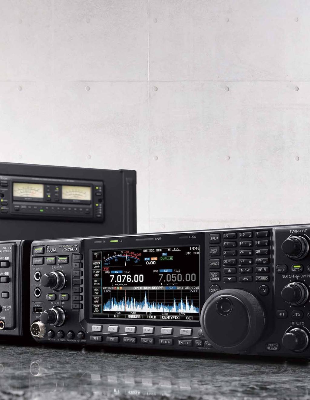
2 Pushing performance to the pinnacle The latest DSP technologies developed for the IC-7800/7700 plus over 45 years of analog circuit expertise give the IC-7600 the performance advantage. The flagship's lineage: dual DSP units, 3kHz 1st (roofing) filter, double-conversion superheterodyne, all direct descendents of the IC-7800/7700. D ual DSP R eceiver System Separate DSP units for transmitter/ receiver and spectrum scope. The double-conversion superheterodyne system and the image rejection mixer improve inband IMD. 1 st IF Filter Three built-in 1st IF (roofing) filters: 3, 6 and 15kHz. HF/50MHz ALL MODE TRANSCEIVER

")


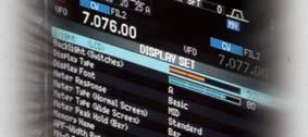
3 D isplay 5.8-inch WQVGA ( pixel) ultra-wide viewing angle TFT display with long-life LED backlighting. S pectrum Scope High-resolution real-time spectrum scope using a dedicated DSP unit. U SB Connectors Easily connect keyboards, flash memory drives, and PCs. P SK Operation Built-in PSK and RTTY operation with a USB keyboard - PC not required.
4 Receiver Performance Inherited from the Flagship Rec Dual DSP for transmitter/receiver and spectrum scope Two separate 32-bit DSP units power the transmitter/receiver and spectrum scope. These processors give the IC-7600 high performance comparable to our top-of-the-line IC-7800 and IC-7700, thanks to the combination of dual DSP and our analog RF design expertise. DSP unit for Transmit and Receive TMS320C6726B (Top in photo) Internal clock speed: 266MHz 32-bit floating point DSP Maximum performance =1600MFLOPS DSP unit for Spectrum scope TMS320C6720 (Bottom in photo) Internal clock speed: 200MHz 32-bit floating point DSP Maximum performance =1200MFLOPS 104dB dynamic range and +30dBm third-order intercept point (IP3) Icom s long years of analog RF circuit experience combined with the latest digital technology results in an astonishing 104dB receiver dynamic range and +30dBm IP3 in the HF bands without sacrificing receiver sensitivity. Even a weak signal adjacent to strong signals is clearly received by the IC Audio output level Dynamic range characteristics [db] Noise floor level +30dBm Antenna Input [dbm] Dual AGC loops controlled by DSP The IC-7600 has dual AGC loops, one analog and one digital, both under DSP control. This architecture prevents strong adjacent signals from "pumping" the AGC and allows maximum dynamic range in the DSP. AGC loop management 2nd mixer(image rejection mixer) 90 Phase shifter DSP Circuit Double-conversion superheterodyne dramatically improves inband IMD 90 Phase shifter The IC-7600 employs a doubleconversion superheterodyne system which has an image rejection mixer for the 2nd mixer stage. When compared to a typical triple-conversion system, the double-conversion system is more difficult to implement but it dramatically reduces signal distortion and provides a high-fidelity RF signal to the DSP processor. Receiver System Typical triple-conversion receiver Audio output level [db] Inband dynamic range characteristics Compared to the IC-756PROIII Noise floor level Antenna Input [dbm] Three built-in 1st IF (roofing) filters, including 3kHz The IC-7600 has three built-in 1st IF (roofing) filters ahead of the 1st IF amplifier stage. The 3kHz filter is especially effective in CW and SSB modes to eliminate overloading caused by strong signals just outside the passband. 6kHz, 3kHz and 15kHz 1st IF filters (from top to bottom) Digital IF filter The IC-7600 double-conversion receiver with image-rejection 2nd mixer The IC-7600 DSP allows you to "build your own" digital IF filter. You can quickly choose bandwidth, shape factor, and center frequency, so that you can work that rare DX station while your competition's still tweaking their transceiver controls. Three filter memories allow you to change filter settings instantly, a great help during contesting or other high-rate operating. Digital IF filter setting example
 to shift and narrow the IF passband until the interference is gone and you")


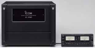
5 eiver performance standards all DX ers have come to expect Above photo includes optional SP-23 and IC-PW1/EURO. Digital twin PBT Noise blanker After "building your own" digital IF filter, you can use digital twin Passband Tuning (PBT) to shift and narrow the IF passband until the interference is gone and you can clearly hear that weak signal. A 100-step digital noise blanker reduces interference from pulse-type noise sources such as engine ignition systems. Digital notch filter Signals such as heterodynes and AM carriers can be eliminated with automatic notch filter technology, making interference from RF sources such as beat signals and RTTY signals a thing of the past. You can also choose three shape factors for the notch filter, to optimize interference rejection. Manual notch filter characteristics Dualwatch function Dualwatch allows you to receive two signals in the same band simultaneously. For example, you can listen to a DX station transmitting on MHz while also listening to the pileup calling him on MHz. Dualwatch receiver (Same band only) Noise reduction The processing power of the 32-bit DSP produces results you can hear! The 16-step variable noise reduction can significantly enhance the receiver's signal-to-noise ratio, giving you a clean, clear audio signal that may make the difference between making the contact or not. Noise Reduction Characteristics Noise Reduction OFF Noise Reduction ON High stability TCXO unit The IC-7600 provides ±0.5ppm frequency stability using a high stability temperature-compensate crystal oscillator (0 C to +50 C). This high stability TCXO unit offers stable operation even during continuous transmission on RTTY or PSK31 mode. TCXO Unit


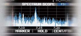
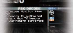
6 Versatile Functions and Intuitive Operation 5.8 inch ultra-wide viewing angle TFT display Digital voice memory The IC-7600's ultra-wide viewing angle display has excellent color rendition and high contrast ratio with fast response time. These features allow the spectrum scope and simulated analog meters to move smoothly and naturally. White LED backlighting offers faster start-up, stable brightness, and very long life. With digital voice memory, you can record the incoming signal and immediately replay the audio, a must-have feature for DXing and contesting. Because the transceiver is recording continuously, time-shift playback can replay the 15 seconds of audio that you heard <before> you pushed the Rec button! The IC-7600 has a 4 channel transmit memory (maximum 90 seconds per channel) and 20 channel receive memory (maximum 30 seconds per channel, total 200 seconds with 20 channels). In addition, the recorded incoming signal can be saved on a USB flash drive. Digital Voice Recorder Voice memory buttons pixels, mm large display Multi-function meter Ultra-wide viewing angle display Photo taken with room light turned off. LCD and backlight Comparison between IC-7600 and IC-756PROⅢ* IC-7600 IC -756PROⅢ Size 5.8 inch WQVGA 5 inch QVGA LCD Viewing Angle 180 (approx.) (Horizontal/Vertical) 90 (approx.) (Horizontal) 60 (approx.) (Vertical) Backlighting Type LED (White) CCFL (Cold cathode fluorescent lamp) *These specifications show the specifications of the individual devices only. Spectrum scope The dedicated spectrum scope DSP with built-in digital filtering greatly improves dynamic range, response time, and frequency accuracy of the spectrum scope. The scope automatically selects the optimum resolution based on the sweep bandwidth. In addition, the spectrum scope range can be set independently from the receiving frequency. You can monitor band conditions between the selected sweep edges (Max. 500kHz) in the fixed mode, as well as sweep a selected band width centered on the receiving frequency in the center mode. The multi-function meter allows you to observe the transmit/receive conditions at a glance. In addition to the signal strength, transmit power level, ALC, compression level and SWR meters, the IC shows the drain terminal voltage of the final amplifier (Vd), the drain current of the final amplifier (Id) and temperature of the PA circuit (TEMP). RF speech compressor Multi-function meter setting screen The digital RF compressor boosts average RF output power, improving signal strength and readability. RTTY/PSK31 operation with a USB keyboard Simply plug in a USB keyboard to operate RTTY and PSK! The digital twinpeak filter greatly reduces interference and a tuning indicator helps you zerobeat the signals. Eight RTTY and PSK transmit memories store up to 62 characters per channel. Triple band stacking register Fix mode screen DSP unit for spectrum scope The triple band stacking register quickly memorizes and calls up the operating frequency and mode for 3 channels on each band. Just push the band key button (ten-key pad), and you can call up the last operating frequency and mode. This function is convenient especially when switching bands during contests, etc.

7 The real performance of the IC-7600 is apparent in the front lines of a DX contest. Programmable band edge beep You can program the band edge not only according to the amateur radio band plan but also more specific frequencies like contest frequencies, CW operating mode, etc. If you try to operate on the OFF band, the transceiver alerts you with a beep sound. You can also inhibit transmitting in the OFF band. Built-in memory keyer Built-in memory keyer provides 4 channels for CW mode and 8 channels each for RTTY and PSK31 modes, capable of storing up to 70 characters for each channel. The memory keyer is useful for sending CQ or exchanging numbers during contests. When not contesting, you can store and send your name, QTH, rig, etc. With a USB keyboard, you can send memory contents using a function key on the keyboard. Memory keyer screen USB connectors on the front and rear panel The IC-7600 has one USB connector on the front panel and one on the rear panel. You can connect a USB keyboard or USB flash drive to the front panel (type A plug) and connect a PC to the rear panel (type B plug). Using the CI-V data format and external software*, you can control the IC-7600 from a PC via the USB port. You can also transfer audio, both transmit and receive, via the USB port. * Software is not supplied from Icom. Microphone equalizer and adjustable transmit bandwidth The built-in audio equalizer has separate bass and treble adjustments for a total of 121 combinations, so you can adjust the tonal quality of your voice as you want. In addition, the transmit bandwidth is selectable from 100, 200, 300, 500Hz at the low-pass edge, and 2500, 2700, 2800, 2900Hz at the high-pass edge, respectively. Three types of high and low combinations can be stored in the memory as favorite settings. With this flexibility of DSP-based waveform shaping, transmit audio quality is adjustable to your preference. High power final amplifiers High-power FET transistors, RD100HHF1, are used in the PA unit providing excellent signal quality and low IMD characteristics. With a large heat sink and cooling fans, reliable 100W output at high duty cycle can be used, for example in contesting or data modes. High power FET Transistors Two types of send relay settings For amplifier keying (SEND jack), you can select either a mechanical relay (max. 16V/500mA) or a FET switch (max. 250V/200mA). The FET switch is designed to key older tube-type amplifiers that may have high voltage on the SEND line. Built-in high-speed automatic antenna tuner USB (type B) connector on the rear panel The antenna tuner memorizes its settings based on your transmit frequency, so that it can rapidly tune when you change bands. High-voltage capacitors allow continuous-duty-cycle full-power operation. Installation example of USB keyboard Other outstanding features [Antenna connectors] Two Tx/Rx antenna connectors with automatic antenna selector Rx antenna In/Out connector for receiver antenna or external attenuator [Receiver] General coverage receiver* covers from 30kHz to 60MHz (* Some frequency bands are not guaranteed, depending on version) Two types of receiver preamplifiers : Preamp 1: Increases low level signal improving intermodulation characteristics Preamp 2: High gain preamplifier Built-in 3-step RF attenuator (6, 12 and 18dB) [Transmitter] Tx monitor 50 CTCSS tone encoder and decoder VOX capability (Voice operated transmission) All mode power control [CW mode] DSP controlled CW keying waveform shaping Multi-function electronic keyer with adjustable keying speed, dot-dash ratio, paddle polarity and bug keyer CW pitch control from 300Hz to 900Hz Double key jack Full break-in function and semi break-in function Adjustable CW envelope [Operation] Digital meter indicates output power, ALC level, SWR, COMP (compression level), Id (drain current of the final amplifier) and Vd (voltage of the final amplifier) Built-in voice synthesizer announces the frequency, mode and S-meter level in English. Set mode function for flexible and speedy setting Memory pad stores up to 5 or 10 operating frequencies Quick split function and frequency lock function Single knob control from RF gain to squelch RIT and delta Tx variable up to ±9.999kHz Two clocks to show local and UTC time 1Hz pitch tuning and indication 101 memories with 10-character name Program, memory, select memory and f scans Auto tuning step function Adjustable tuning dial tension Dial lock Band edge beep (Can be disabled) AH-4 control circuit Automatic tuning speed for data mode operation CI-V interface with optional CT-17 Screen saver function Rear panel view Ground Terminal Antenna Connectors DC Power Socket Transverter Jack Receive Antenna Connectors ALC Input Jack SEND Control Jack Tuner Control Socket Accessory Sockets Key Jack Meter Jack USB Connector CI-V Remote Control Jack External Speaker Jack
8
HF/50MHz TRANSCEIVER
 HF/50MHz TRANSCEIVER D isplay Pushing performance to the pinnacle The latest DSP technologies developed for the flagship models plus many decades of analog circuit expertise give the the performance advantage.
Icom IC-9100 HF/VHF/UHF transceiver
 263 Walsall Road, Great Wyrley, Walsall, WS6 6DL Established 1997. Open Monday - Friday 9am - 5pm and Saturday 9.30am - 4pm Tel: 01922 414 796 Fax: 01922 417829 Skype: radioworld_uk Icom IC-9100 HF/VHF/UHF
SPECS FEATURES SUPPLIED ACCESSORIES. HF All Band Transceiver
 718 HF All Band Transceiver RX 0.030-29.999999MHz* TX 1.800-1.999999 MHz** 3.500-3.999999 MHz** 7.000-7.300000 MHz 10.100-10.150000 MHz 14.000-14.350000 MHz 18.068-18.168000 MHz 21.000-21.450000 MHz 24.890-24.990000
December A top of the line transceiver with ultimate receiver performance
 December 2007 HF/50MHz TRANSCEIVER i7700 A top of the line transceiver with ultimate receiver performance To claim the right of being a top of the line transceiver, it is necessary to have the absolute
The amazing evolution of the 706 series
 The amazing evolution of the 706 series The IC-706MKIIG carries on the 706 series tradition of base station performance and features in a mobile reg-sized package. Building on this legacy, frequency coverage
The Icom IC Adam Farson VA7OJ. A New Top-class HF/6m Transceiver. IC-7700 Information & Links
 The Icom IC-7700 A New Top-class HF/6m Transceiver Adam Farson VA7OJ IC-7700 Information & Links Copyright 2008 North Shore Amateur Radio Club NSARC HF Operators IC-7700 1 IC-7700 front panel This is a
From 40 years of RF design expertise comes the Masterpiece Ham Radio Transceiver
 From 40 years of RF design expertise comes the Masterpiece Ham Radio Transceiver Icom is a pioneer in the amateur radio world. Starting with the first analog PLL circuit in the IC-200 to the ground-breaking
LnR Precision, Inc. 107 East Central Avenue, Asheboro, NC
 LD5 CW/SSB QRP Transceiver Quick guide manual Description: At the development base of the digital signal processing unit, an algorithm is embedded for IQ processing of the channels with phase suppression
LD5 CW/SSB QRP Transceiver SDR /DSP
 LD5 CW/SSB QRP Transceiver SDR /DSP Quick guide manual Description: At the development base of the digital signal processing unit, an algorithm is embedded for IQ processing of the channels with phase
Four 32-bit floating point DSP units +40dBm ultra high intercept point
 Icom has been the world pioneer in amateur radio for 40 years. The first to bring transistor technology, digital PLL technology and the latest DSP technology to name a few achievements. It is therefore
TS-590SG HF/ 50MHz All-Mode TRANSCEIVER_
 New Product Release Information Oct 2014 TS-590SG HF/ 50MHz All-Mode TRANSCEIVER_ Kenwood introduces Updated to new G version new HF/50MHz All-Mode Transceiver Four years ago we launched our best-selling
From 40 years of RF design expertise comes the Masterpiece Ham Radio Transceiver
 From 40 years of RF design expertise comes the Masterpiece Ham Radio Transceiver Icom is a pioneer in the amateur radio world. Starting with the first analog PLL circuit in the IC-200 to the ground-breaking
Transceiver selection and Specs.
 Transceiver selection and Specs. Transceivers 1956-2018 From TUBES to SDR Covers 20-10 meters in 100Khz segments, 10 available, crystal needed for each. Plug in crystal holder. 100 Watts output, final
Technician License Course Chapter 5. Lesson Plan Module 11 Transmitters, Receivers and Transceivers
 Technician License Course Chapter 5 Lesson Plan Module 11 Transmitters, Receivers and Transceivers Generalized Transceiver Categories Mobile Single Band Dual Band All Band Multimode Handheld (HT) VHF/UHF
Icom IC-7851 HF & 50MHz transceiver
 Icom IC-7851 HF & 50MHz transceiver A new flagship is born: the current market leader in terms of performance 36 PHOTO 1: IC-7851 front view. INTRODUCTION. In 2004, Icom launched their IC-7800 top-of-the-range
RF Direct Sampling Takes You to the Next Level
 HF/50MHz TRANSCEIVER RF Direct Sampling Takes You to the Next Level Outstanding HF Experience Right Here RF Direct Sampling Takes You to the Next Level with Advanced RMDR and True Dual Receive Whether
ICOM IC-R8600 Specifications, Features & Options
 General Frequency coverage IC-R8600 USA: 0.010000 821.999999MHz*, 851.000000 866.999999MHz, 896.000000 3000.000000MHz (*Guaranteed range: 0.100000 821.999999MHz) Antenna connector Frequency stability Mode
i2820h (USA) ie2820(europe)
 ie2820(europe)") January 2007 DUAL BAND TRANSCEIVERS i2820h (USA) ie2820(europe) The above photo shows the IC-2820H. The IC-E2820 differs slightly from this photo. Icom proudly announces the debut of the new dual band
January 2007 DUAL BAND TRANSCEIVERS i2820h (USA) ie2820(europe) The above photo shows the IC-2820H. The IC-E2820 differs slightly from this photo. Icom proudly announces the debut of the new dual band
Elmer Session Hand Out for 3/3/11 de W6WTI. Some Common Controls Found On Amateur Radio Transceivers. (From ARRL web site tutorial)
") Elmer Session Hand Out for 3/3/11 de W6WTI Some Common Controls Found On Amateur Radio Transceivers. (From ARRL web site tutorial) The placement of the controls may vary from manufacturer to manufacturer
Elmer Session Hand Out for 3/3/11 de W6WTI Some Common Controls Found On Amateur Radio Transceivers. (From ARRL web site tutorial) The placement of the controls may vary from manufacturer to manufacturer
From 40 years of RF design expertise comes the Masterpiece Ham Radio Transceiver
 From 40 years of RF design expertise comes the Masterpiece Ham Radio Transceiver Icom is a pioneer in the amateur radio world. Starting with the first analog PLL circuit in the IC-200 to the ground-breaking
GRAND STRAND AMATEUR RADIO CLUB
 The GRAND STRAND AMATEUR RADIO CLUB (GSARC) Myrtle Beach SC is offering used amateur related equipment for sale. Written bids may be submitted to the GSARC up to Friday, November 23 rd, 2018. Only currently
IC-756 Pro III vs. Pro II
 IC-756 Pro III vs. Pro II Improvements in the Pro III vs. the Pro II Adam Farson VA7OJ IC-756Pro3 Information & Links Copyright 2006 North Shore Amateur Radio Club NSARC HF Operators 756Pro3 vs. Pro2 1
GETTING THE MOST FROM YOUR HF TRANSCEIVER FRED KEMMERER, AB1OC JANUARY 10 TH, 2017
 GETTING THE MOST FROM YOUR HF TRANSCEIVER FRED KEMMERER, AB1OC JANUARY 10 TH, 2017 Topics Its mostly about the receiver Transmitter/amplifier operation tips and tricks Common operating scenarios Not to
2012 Edition HAM RADIO PRODUCTS. All Band Transceivers. Mobile Transceivers. Handheld Transceivers. Base Station Transceivers
 2012 Edition HAM RADIO PRODUCTS All Band Transceivers Mobile Transceivers Handheld Transceivers Base Station Transceivers Icom s flagship HF transceiver +40dBm 3rd order intercept point (in the HF bands)
i7610 Technical Report Volume 1
 i7610 Technical Report Volume 1 ~ Profile ~ Outstanding HF Experience Right Here Icom s mid class HF transceivers evolved especially with the IC-756, IC- 756PRO and IC-7600, and were technology leaders
i7610 Technical Report Volume 1
 i7610 Technical Report Volume 1 ~ Profile ~ Outstanding HF Experience Right Here Icom s mid class HF transceivers evolved especially with the IC-756, IC756PRO and IC-7600, and were technology leaders in
THE TRANSCEIVER Instruction Manual
 THE TRANSCEIVER i7800 Instruction Manual A-6328H-1EX-q Printed in Japan 2004 Icom Inc. FOREWORD Congratulations! You are the owner of the world s most advanced amateur HF/50 MHz transceiver IC-7800. The
Development of the QSX transceiver kit
 Development of the QSX transceiver kit Norfolk Amateur Radio Club Wednesday 9-Jan-2019 Hans Summers, G0UPL http://qrp-labs.com QCX 5W CW transceiver kit QRP Labs CW Xcvr Introduced at YOTA 2017 summercamp
DX AM FM SSB CW PA Amateur Base Station Transceiver OWNER S MANUAL RX / TX 2 4 POWER NF CHANNEL MODE RF POWER OFF CAL OFF OFF CALIBRATE
 1 2 3 6 4050 ULA 6070 TI 80 90 100 9 DX 2517 2517 RX / TX 0 2 4 SWR WATTS SET 81012 22 1 010 3 2030 5 MOD 7 ON dbover 9 SIGNAL +20 +40+60 PA FM AM USB LSB CW POWER ON SWR NB / ANL R.BEEP +10KHz NF CHANNEL
SUBELEMENT T4. Amateur radio practices and station set up. 2 Exam Questions - 2 Groups
 SUBELEMENT T4 Amateur radio practices and station set up 2 Exam Questions - 2 Groups 1 T4A Station setup: connecting microphones; reducing unwanted emissions; power source; connecting a computer; RF grounding;
Technician License Course Chapter 3 Types of Radios and Radio Circuits. Module 7
 Technician License Course Chapter 3 Types of Radios and Radio Circuits Module 7 Radio Block Diagrams Radio Circuits can be shown as functional blocks connected together. Knowing the description of common
INSTALLATION AND CONNECTIONS Section 2
 STLLTION ND CONNECTIONS Section Unpacking - ntenna jumper cable connection - Selecting a location - Rack mounting handle attachment - Grounding -3 ntenna connection -3 CF (Compact Flash) memory card -3
HF Receivers, Part 2
 HF Receivers, Part 2 Superhet building blocks: AM, SSB/CW, FM receivers Adam Farson VA7OJ View an excellent tutorial on receivers NSARC HF Operators HF Receivers 2 1 The RF Amplifier (Preamp)! Typical
Icom IC A Look Under the Hood Bruce Wampler - WA7EWC
 Icom IC-7300 A Look Under the Hood Bruce Wampler - WA7EWC The Icom IC-7300 is a brand new (April 2016), Direct Conversion, 100% SDR. It is the first SDR amateur radio transceiver by one of the major Japanese
LBI-31564A. Mobile Communications. DELTA - SX MHz RADIO COMBINATIONS (NEGATIVE GROUND ONLY) Maintenance Manual
 Maintenance Manual") A Mobile Communications DELTA - SX 136-174 MHz RADIO COMBINATIONS (NEGATIVE GROUND ONLY) Maintenance Manual TABLE OF CONTENTS MILITARY AND SYSTEM SPECIFICATIONS................................. 2-3 COMBINATION
A Mobile Communications DELTA - SX 136-174 MHz RADIO COMBINATIONS (NEGATIVE GROUND ONLY) Maintenance Manual TABLE OF CONTENTS MILITARY AND SYSTEM SPECIFICATIONS................................. 2-3 COMBINATION
18-CHANNEL MOBILE CB TRANSCEIVER MODEL CB-845
 18-CHANNEL MOBILE CB TRANSCEIVER MODEL CB-845 INSTRUCTION HANDBOOK RAll JEFFERSOn CITIZEN BAND RADIO MESSAGE TO THE OWNER CONGRATULATIONS! As the new owner of Ray Jefferson Model CB-845 CB Mobile Transceiver,
Second Hand Yaesu FTDX5000MP HF base station transceiver
 263 Walsall Road, Great Wyrley, Walsall, WS6 6DL Established 1997. Open Monday - Friday 9am - 5pm and Saturday 9.30am - 4pm Tel: 01922 414 796 Fax: 01922 417829 Skype: radioworld_uk Second Hand Yaesu FTDX5000MP
Operation Manual. SlJPER ST AR Channel Mobile 5-Mode Transceiver -----~- --:.. KTSS200NXX ,, I
 Operation Manual!.,, SlJPER ST AR 2000 200 Channel Mobile 5-Mode Transceiver -----~- --:.. KTSS200NXX General Description l Frequency/Channel Chart The Super Star -2000 is a combination transmitter-receiver
Radio Receivers. Al Penney VO1NO
 Radio Receivers Al Penney VO1NO Role of the Receiver The Antenna must capture the radio wave. The desired frequency must be selected from all the EM waves captured by the antenna. The selected signal is
IC-F7000. Advanced selective call and ALE make HF communication easier than ever!
 Page 1 of 5 HF TRANSCEIVER IC-F7000 Advanced selective call and ALE make HF communication easier than ever! The IC-F7000 is an HF land mobile transceiver especially designed forlong distance communications.
ADJUSTING YOUR HF RECEIVER
 ADJUSTING YOUR HF RECEIVER N5KIP January 31, 2017 Disclaimers What works on one model of radio might not work well on another CW (narrow bandwidth) and SSB (wider bandwidth) will require different receiver
ARRL Laboratory Expanded Test-Result Report ICOM IC-756 Pro
 ARRL Laboratory Expanded Test-Result Report ICOM IC-756 Pro Prepared by: American Radio Relay League, Inc. Technical Department Laboratory 225 Main St. Newington, CT 6111 Telephone: (8) 594-2 Web Site:
STORING MESSAGES Note: If [MEMORY] (F5) is unavailable in the function key guide, press [MORE] (F2). An alternate key guide will appear.
![STORING MESSAGES Note: If [MEMORY] (F5) is unavailable in the function key guide, press [MORE] (F2). An alternate key guide will appear.](/thumbs/92/107920661.jpg "STORING MESSAGES Note: If [MEMORY] (F5) is unavailable in the function key guide, press [MORE] (F2). An alternate key guide will appear.") ASSISTING YOUR SMOOTH QSO 5 If letters not transmitted yet remain in the text string buffer when [F12] is pressed at step 6, "WAIT" appears on the status bar. When the entire text string is transmitted,
ASSISTING YOUR SMOOTH QSO 5 If letters not transmitted yet remain in the text string buffer when [F12] is pressed at step 6, "WAIT" appears on the status bar. When the entire text string is transmitted,
HF/50MHz TRANSCEIVER. Perfection. In its purest form...
 HF/50MHz TRANSCEIVER Perfection In its purest form... 1 To Amateurs That Share An Appreciation of Design and Value The IC-7700 For Operators With A Common Vision of Design and Value. The essential elements
INSTRUCTION MANUAL. HF/50 MHz ALL MODE TRANSCEIVER
 INSTRUCTION MANUAL HF/50 MHz ALL MODE TRANSCEIVER This device complies with Part 5 of the FCC rules. Operation is subject to the following two conditions: () This device may not cause harmful interference,
All Things icom Microphone Basics
 All Things icom Microphone Basics 22 June 2016 - Reprinted with permission from the Heil. http://www.heilsound.com/amateur/support/dsp-settings/all-things-icom Important! The icom 7300 has been updated
Radio Receivers. Al Penney VO1NO
 Radio Receivers Role of the Receiver The Antenna must capture the radio wave. The desired frequency must be selected from all the EM waves captured by the antenna. The selected signal is usually very weak
FT-897 Alignment. Local Oscillator Adjustment. PLL Adjustment
 FT-897 Local Oscillator Adjustment Reference Frequency Adjustment a. Connect a frequency counter to TP1032. b. Adjust the trimmer capacitor (TC5001) for 67.875000MHz ±5Hz on the frequency counter. c. Connect
INSTRUCTION MANUAL. HF/50 MHz TRANSCEIVER. i7410
 INSTRUCTION MANUAL HF/0 MHz TRANSCEIVER i0 i FOREWORD Thank you for making the IC-0 your radio of choice. We hope you agree with Icom s philosophy of technology first. Many hours of research and development
RF Direct Sampling Takes You to the Next Level
 HF/50MHz TRANSCEIVER RF Direct Sampling Takes You to the Next Level Outstanding HF Experience Right Here RF Direct Sampling Takes You to the Next Level with Advanced RMDR and True Dual Receive Whether
CON NEX HP. OWNER'S MANUAL Full Channel AM/FM Amateur Mobile Transceiver TABLE OF CONTENTS TUNING THE ANTENNA FOR OPTIMUM S.W.R..
 TABLE OF CONTENTS PAGE SPECIFICATIONS... 2 INSTALLATION... 3 LOCATION... 3 CON NEX - 4300HP MOUNTING THE RADIO... 3 IGNITION NOISE INTERFERENCE... 4 ANTENNA... 4 TUNING THE ANTENNA FOR OPTIMUM S.W.R..
Peerless Performance TS-590S. HF / 50 MHz ALL MODE TRANSCEIVER
 Peerless Performance TS-590S HF / 50 MHz ALL MODE TRANSCEIVER Discovering the Hidden The TS-590S marks a bold new chapter in Kenwood s proud history of high-performance HF transceivers. Featuring a narrow-band
INSTRUCTION MANUAL. HF/50 MHz TRANSCEIVER. i7200
 INSTRUCTION MANUAL HF/ MHz TRANSCEIVER i IMPORTANT R E A D T H I S I N S T RU C T I O N M A N UA L CAREFULLY before attempting to operate the transceiver SAVE THIS INSTRUCTION MANUAL This manual contains
INSTRUCTION MANUAL VHF/UHF ALL MODE TRANSCEIVER. i910h
 INSTRUCTION MANUAL VHF/UHF ALL MODE TRANSCEIVER i910h IMPORTANT EXPLICIT DEFINITIONS READ THIS INSTRUCTION MANUAL CAREFULLY before attempting to operate the transceiver. SAVE THIS INSTRUCTION MANUAL. This
E L E C R A F T K 2 R E V I S I O N 2 F I R M W A R E
 E L E C R A F T K 2 R E V I S I O N 2 F I R M W A R E Installation and Reference Manual Rev. B, August 28, 2001 Summary of Changes... 2 Computer Control (KIO2)... 2 Transverter Bands... 2 RTTY/Data Mode
HR MHZ AM-FM AMATEUR RADIO HF TRANSCEIVER OWNER'S MANUAL. Content of the packaging
 HR-2800 28 MHZ AM-FM AMATEUR RADIO HF TRANSCEIVER OWNER'S MANUAL NOTICE! It is recommended to carefully read this owner s manual before using the product. This will also help to prevent illegal use of
KWM-2/2A Transceiver THE COLLINS KWM-2/2A TRANSCEIVER
 KWM-2/2A Transceiver Click the photo to see a larger photo Click "Back" button on browser to return Courtesy of Norm - WA3KEY THE COLLINS KWM-2/2A TRANSCEIVER Unmatched for versatility, dependability and
Operating Station Equipment
 Amateur Radio License Class Operating Station Equipment Presented by Steve Gallafent October 3, 2007 Operating Station Equipment Modulation Modulation is the process of adding information to a radio signal
Preliminary features of the SDR-X receiver SDR-X , PowerSDR Winrad Winrad DDS SFDR SFDR AD995 AD99 1
 Preliminary features of the SDR-X receiver The SDR-X receiver, in its full version is capable of continuously tuning the entire HF spectrum, 6m ( 50-52 MHz) band included. SSB, AM etc. demodulation, bandpass
HF Receivers, Part 3
 HF Receivers, Part 3 Introduction to frequency synthesis; ancillary receiver functions Adam Farson VA7OJ View an excellent tutorial on receivers Another link to receiver principles NSARC HF Operators HF
SPECIFICATIONS GENERAL RECEIVER
 HF/50MHz TRANSCEIVER Whether it is poor band conditions, or battling to pick out a call in a large pile-up, faint signals have always been a challenge for DXers and Contesters around the world. The difference
 HF Receiver Testing: Issues & Advances (also presented at APDXC 2014, Osaka, Japan, November 2014) Adam Farson VA7OJ Copyright 2014 North Shore Amateur Radio Club NSARC HF Operators HF RX Testing 1 HF
RF Direct Sampling Takes You to the Next Level
 HF/50MHz TRANSCEIVER RF Direct Sampling Takes You to the Next Level Outstanding HF Experience Right Here RF Direct Sampling Takes You to the Next Level with Advanced RMDR and True Dual Receive Whether
CI-V REFERENCE GUIDE. HF/50MHz TRANSCEIVER. i7610
 CI-V REFERENCE GUIDE HF/50MHz TRANSCEIVER i7610 Table of contents Remote control 2 Remote control (CI-V) information 2 DDCI-V connection 2 DDPreparing 2 DDAbout the data format 2 DDCommand table 3 DDCommand
QUICK REFERENCE GUIDE
 QUICK REFERENCE GUIDE Installation 1. Install a ground system for DC noise suppression and RFI suppression 2. Install your DC power supply 3. Install lightning protection. This will help protect more than
i78 INSTRUCTION MANUAL HF TRANSCEIVER
 INSTRUCTION MANUAL HF TRANSCEIVER i78 This device complies with Part 15 of the FCC rules. Operation is subject to the following two conditions: (1) This device may not cause harmful interference, and (2)
TABLE OF CONTENTS TABLE OF CONTENTS 1
 TABLE OF CONTENTS TABLE OF CONTENTS 1 Chapter 1 YOUR NEW ORION II ORION II ANOTHER STEP FORWARD IN TEN-TEC INNOVATION 4 UNPACKING YOUR NEW ORION II 4 ABOUT THIS MANUAL 4 CONNECTING A POWER SUPPLY 5 A WORD
INSTRUCTION MANUAL. HF/VHF ALL MODE TRANSCEIVER i746pro
 INSTRUCTION MANUAL HF/VHF ALL MODE TRANSCEIVER i746pro This device complies with Part 15 of the FCC rules. Operation is subject to the following two conditions: (1) This device may not cause harmful interference,
JUMA-TRX2 DDS / Control Board description OH2NLT
 JUMA-TRX2 DDS / Control Board description OH2NLT 22.08.2007 General Key functions of the JUMA-TRX2 DDS / Control board are: - provide user interface functions with LCD display, buttons, potentiometers
Midland 248XL I NSTRUCTION GUI DE
 Midland 248XL I NSTRUCTION GUI DE INDEX Introduction...2 Function and location of the controls...3 Installation...7 Power supply...7 Installing an antenna...7 How to use your Midland 248XL...8 Frequency
Roofing Filters, Transmitted BW and Receiver Performance
 Roofing Filters, Transmitted BW and Receiver Performance Rob Sherwood NCØB What s important when it comes to choosing a radio? Sherwood Engineering Why Did I Start Testing Radios? Purchased a new Drake
RF Direct Sampling Takes You to the Next Level
 HF/50MHz TRANSCEIVER RF Direct Sampling Takes You to the Next Level Outstanding HF Experience Right Here RF Direct Sampling Takes You to the Next Level with Advanced RMDR and True Dual Receive Whether
HF Transceiver Notes (July 2015) Bill Shanney, W6QR
 Bill Shanney, W6QR") HF Transceiver Notes (July 2015) Bill Shanney, W6QR w6qr@arrl.net HF Station Considerations If you ask a contester what the most important part of their station is they will tell you it is the antenna
HF Transceiver Notes (July 2015) Bill Shanney, W6QR w6qr@arrl.net HF Station Considerations If you ask a contester what the most important part of their station is they will tell you it is the antenna
User Manual. Specifications...3. Control and Operation Microphone...8. Installation...9. Installation of Main Unit...9
 Contents Specifications...3 Control and Operation...4-7 Microphone...8 Installation...9 Installation of Main Unit...9 Antenna Installation...9 Operational test...9 Frequency Bands Table...10 Frequency
2014 Edition HAM RADIO PRODUCTS. All Band Transceivers. Mobile Transceivers. Handheld Transceivers. Base Station Transceivers
 2014 Edition HAM RADIO PRODUCTS All Band Transceivers Mobile Transceivers Handheld Transceivers Base Station Transceivers Icom s flagship HF transceiver +40dBm 3rd order intercept point (in the HF bands)
Screen shots vary slightly according to Windows version you have.
 http://www.w1hkj.com/fldigihelp/audio_adjust_page.html Screen shots vary slightly according to Windows version you have. Receive audio Setting the correct hardware, operating system, and fldigi received
KENWOOD SKY COMMAND SYSTEM
 KENWOOD SKY COMMAND SYSTEM Operation Manual KENWOOD COMMINICATIONS CORPORATION KENWOOD COMMUNICATIONS CORPORATION This operation manual is used for the KENWOOD SKY COMMAND SYSTEM (hereinafter referred
Technical Equipment Specification
 STATE OF CALIFORNIA Office of the State Chief Information Officer Public Safety Communications Division Technical Equipment Specification Equipment Type: Transmitter/Receiver Mobile Relay/Base/Control
Ten-Tec Orion/Orion II Users Manual Addendum Firmware Version V3
 Ten-Tec Orion/Orion II Users Manual Addendum Firmware Version V3 It is very important that you read this document in its entirety before using the V3 firmware. Some features behave differently than they
Roofing Filters, Transmitted BW and Receiver Performance
 Roofing Filters, Transmitted BW and Receiver Performance Rob Sherwood NCØ B What s important when it comes to choosing a radio? Sherwood Engineering Why Did I Start Testing Radios? Purchased a new Drake
Youkits SK-1A 40m SSB/CW QRP Transceiver. Operating manual
 Youkits SK-1A 40m SSB/CW QRP Transceiver Operating manual Specifications Size: 88*38*124mm (not including knob, etc.) Weight: about 280g (not including battery pack) Supply voltage: 10-15VDC Current drain
HF Transceiver TS-570S(G) HF+6m Transceiver
 HF+6m Transceiver") TS-570D(G) HF Transceiver TS-570S(G) HF+6m Transceiver Advanced Digital Technology for Everyone Kenwood has brought the best of HF DSP technology out of the clouds and into the hands of everyone with the
TS-570D(G) HF Transceiver TS-570S(G) HF+6m Transceiver Advanced Digital Technology for Everyone Kenwood has brought the best of HF DSP technology out of the clouds and into the hands of everyone with the
Kenwood TS-590S Peter Hart reviews the latest HF & 50MHz transceiver
 RADCOM JANUARY 2011 PETER HART, G3SJX E-MAIL: PETER@G3SJX.FREESERVE.CO.UK Kenwood TS-590S Peter Hart reviews the latest HF & 50MHz transceiver PHOTO 1: General view of the Kenwood TS-590S. INTRODUCTION.
Peerless Performance TS-590S. HF / 50 MHz ALL MODE TRANSCEIVER
 Peerless Performance HF / 50 MHz ALL MODE TRANSCEIVER Discovering the Hidden The marks a bold new chapter in Kenwood s proud history of high-performance HF transceivers. Featuring a narrow-band Roofing
Distinctive Performance TS-590S HF/50 MHz ALL MODE TRANSCEIVER
 Distinctive Performance TS-590S HF/50 MHz ALL MODE TRANSCEIVER ABOUT THIS MANUAL This in-depth manual is intended to explain the features of the TS-590S and its convenient use. We hope that this manual,
Module 8 Theory. dbs AM Detector Ring Modulator Receiver Chain. Functional Blocks Parameters. IRTS Region 4
 Module 8 Theory dbs AM Detector Ring Modulator Receiver Chain Functional Blocks Parameters Decibel (db) The term db or decibel is a relative unit of measurement used frequently in electronic communications
RCI-6300F25/150. Owner's Manual. AM/FM Amateur Transceiver With Built-in Frequency Counter. Table of Contents. Downloaded from
 Table of Contents RCI-6300F25/150 AM/FM Amateur Transceiver With Built-in Frequency Counter PAGE Chapter 1 Specifications...... 2 Chapter 2 Installation...... 3 Installing the Radio... 3 Ignition Noise
Barrett 950 HF transceiver specifications Using measurement methods described in European Telecommunication Standard
 Barrett 950 HF transceiver specifications Using measurement methods described in European Telecommunication Standard 300 373. General Specifications Equipment Standards Transmit frequency range Receive
Receiver Performance Transmitted BW Contest Fatigue Rob Sherwood NCØ B
 Receiver Performance Transmitted BW Contest Fatigue Rob Sherwood NCØ B Limitations to a better contest score may not always be obvious. Sherwood Engineering What is important in a contest environment?
Icom IC-7851 HF and 6 Meter Transceiver
 Product TechnicalReview Mark by Mark J. Wilson, Spencer, K1RO, WA8SME k1ro@arrl.org Icom IC-7851 HF and 6 Meter Transceiver Icom s flagship transceiver gets a makeover and a significant performance boost.
Icom IC-7300 HF and 6 Meter Transceiver
 Product TechnicalReview Mark by Mark J. Wilson, Spencer, K1RO, WA8SME k1ro@arrl.org Icom IC-7300 HF and 6 Meter Transceiver Icom s software defined radio (SDR) in a box with knobs. Reviewed by Steve Ford,
i746 INSTRUCTION MANUAL VHF/HF ALL MODE TRANSCEIVER
 INSTRUCTION MANUAL VHF/HF ALL MODE TRANSCEIVER i746 This device complies with Part 5 of the FCC rules. Operation is subject to the following two conditions: () This device may not cause harmful interference,
Receiver Performance Transmitted BW Contest Fatigue Rob Sherwood NCØ B
 Receiver Performance Transmitted BW Contest Fatigue Rob Sherwood NCØ B Limitations to a better contest score may not always be obvious. Sherwood Engineering What is important in a contest environment?
LNR Precision Mountain Topper MTR-4B and MTR-5B REV 2.0 User Manual for use with versions with 16 x 2 display.
 LNR Precision Mountain Topper MTR-4B and MTR-5B REV 2.0 User Manual for use with versions with 16 x 2 display. Four band MTR 4B shown Overview: The Mountain Topper Rigs are designed to be a very small,
HAM Radios and Receivers European Edition
 HAM Radios and Receivers 2018 2019 European Edition RMDR (Reciprocal Mixing Dynamic Range) of 110 db* (at 1 khz) Completely Independent Dual Receivers Receive Two Bands Simultaneously High-Speed, High-Resolution
HAM RADIOS. Mobile. Multi-Band. Handheld. Base Station Europe Edition. Transceivers. Transceivers. Transceivers.
 HAM RADIOS 2017 Europe Edition Mobile Transceivers Multi-Band Transceivers Handheld Transceivers Base Station Transceivers RMDR (Reciprocal Mixing Dynamic Range) of 110 db* (at 1 khz) Completely Independent
HAM RADIOS. Multi-Band. Mobile Transceivers. Base Station Transceivers. Handheld Edition. Transceivers. Transceivers
 HAM RADIOS 2017 Edition Mobile Transceivers Multi-Band Transceivers Handheld Transceivers Base Station Transceivers RMDR (Reciprocal Mixing Dynamic Range) of 110 db* (at 1 khz) High-Speed, High-Resolution
Application Note: Testing P25 Conventional Radios Using the Freedom Communications System Analyzers
 : Testing P25 Conventional Radios Using the Freedom Communications System Analyzers FCT-1007A Motorola CPS and Tuner Software Motorola provides a CD containing software programming facilities for the radio
Testing Motorola P25 Conventional Radios Using the R8000 Communications System Analyzer
 Testing Motorola P25 Conventional Radios Using the R8000 Communications System Analyzer Page 1 of 24 Motorola CPS and Tuner Software Motorola provides a CD containing software programming facilities for
NOTE FTDX9000 CAT OPERATION REFERENCE BOOK FTDX9000 OPERATING MANUAL
 NTE FTD9000 CAT PERATIN REFERENCE BK FTD9000 PERATING MANUAL CAT (CMPUTER AIDED TRANSCEIVR) PERATIN VERVIEW The CAT (Computer Aided Transceiver) System in the FTD9000 provides control of frequency, VF,