MODEL AV-680 INSTRUCTION MANUAL. 308 Industrial Park Road Starkville, MS USA Ph:(662) Fax: (662) Made in USA REV A2
|
|
|
- Griselda Joseph
- 6 years ago
- Views:
Transcription
 323-9538 Fax: (662) 323-6551 Made in USA 925-0680-REV")
1 MODEL AV-680 INSTRUCTION MANUAL 308 Industrial Park Road Starkville, MS USA Ph:(662) Fax: (662) Made in USA REV A2
2 Introduction Hy-Gain is proud to deliver the AV-680 Nine Band Vertical. Drawing on our many years of Amateur Radio HF and VHF antenna design experience, we have produced a wellengineered antenna capable of maximum efficiency, unmatched performance, and superior construction. Computer optimization of the AV-680 design yields the most efficient 3/8 wavelength electrical design with maximum gain and low angle of radiation for long distance communication. No traps are used to achieve nine band performance. The AV-680 is resonant on 6, 10, 12, 15 and 17 meters with individual 3/8 wavelength radiators. The center radiator resonates on 20, 30, 40 and 80 meters using parallel end loaded Teflon wire coils. Capacity hats on these bands give wide 2:1 VSWR bandwidth and the antenna is kept to a height of 27 feet by the low inductance coils. There are no "tricks" or "mystery resonances" used for impedance matching on any band. No long-wire radials or counterpoise kits are necessary for operation of the AV680. The AV-680 is self contained for simple, convenient portable or fixed operation. Mechanical construction of the AV-680 is designed for extreme light weight and high wind survival. Aircraft grade 6063-T832 aluminum and high strength fiberglass are used for the entire radiator. The trap-free design presents a very low wind surface area. Bulky tubing is not required to support unwieldy traps. The broad 2:1 VSWR bandwidth on all bands lessens large frequency shifts seen in other antennas when the antenna is wet or iced. The AV-680 is covered by our Hy-Gain Warranty and supported by our customer service team. We would like to thank you for purchasing this product from us and ask that you let us know of any suggestion you may have. With proper assembly, installation, and maintenance, your AV-680 will provide years of faithful service. Theory of Operation The AV-680 HF Multiband Vertical antenna consists of an end fed radiator that is resonant in the 6, 10, 12, 15, 17, 20, 30, 40 and 80 meter amateur frequency bands. Resonances on each band are the result of impedance matching a 3/8 wavelength element with a broadband RF transformer. The characteristic impedance at the base of the 3/8 wavelength radiator is in the order of a few hundred ohms. To match this impedance two tools are employed. First a counterpoise of 72" spokes is mounted at the AV-680 base. The capacitance from this ground plane 2
3 helps lower the base impedance. Second, a 4:1 toroidal transformer (voltage balun) steps the base impedance down to 50 ohms. This transformer uses a ferrite core for high power capability. Also, the windings are made of twisted pair wire to improve coupling and reduce loss. A second high power transformer is configured as a 1:1 current balun to help stop RF from traveling back on the feedline shield. The radiator of the AV-680 is at DC ground potential for static drain. This is accomplished by a radio frequency choke in the matching circuit. The center radiator of the AV-680 supports 1/4 wavelength stubs for 6, 10, 12 and 17 meters. The stubs are placed approximately one tenth of a wavelength (electrically 1/8 wavelength) above the AV-680 base. At the top of each stub the impedance is very high at the frequency the stub is tuned. This high impedance stops, (chokes) RF at this point creating a resonant 3/8 wavelength radiator. There is minimal loss using this method as compared to standard trap circuits. Also, VSWR bandwidth is not restricted by the Q" of trap components. For 20, 30, 40 and 80 meters, a coil and capacity hat are used on each band to create a 3/8 wavelength radiator. The coils are mounted at the top of the center radiator. These foer coils are connected in parallel. Parallel connection separates each band to allow individual band tuning and has less loss than does series connection. Also, the AV-680 coils have significantly less loss than a standard trap because the AV- 680 capacity hats exhibit greater capacitance than a typical trap, therefore, less inductance is required. Antenna Location The best performance for receiving and transmitting will be obtained by mounting the antenna in a clear location above or away from buildings, buildings, towers, feedlines, utility wires, and other antennas. While your own ingenuity and particular circumstances will determine the final mounting method, remember, any object within 75 feet from the base of the antenna can influence the performance of the AV-680. WARNING: Always mount this antenna so that it is out of the reach of adults as well as children and pets. The counterpoise rods can cause injury and or severe RF burns. NEVER mount this antenna in a location that will permit unsuspecting people to come in contact with any part of the antenna. NEVER mount this antenna where a mechanical failure might allow the antenna, antenna support or feedline to contact power lines or other utility wires. ALWAYS ground the feedline at the point where it enters a building to a good earth ground for lightning protection. ALWAYS follow the guidelines for antenna installations as recommended by the US Consumer Product Safety Commission. 3
4 Antenna Mast The recommended support mast for the AV-680 is steel water pipe between the sizes of 1-3/4" OD to 2 1/2" OD and with a length that will place the antenna base at a safe height. Do not use thin walled conduit, aluminum tubing, or "TV" mast. The AV-680 is designed to operate at a height of 8 or more feet for proper performance. Placement on the side of a house or garage at eaves level is acceptable as long as the counterpoise whips will not be in contact any snow on the roof. Placement above metal roofs is acceptable if the antenna base is at least 5 feet or more above the metal surface. Antenna Grounding Although the AV-680 is designed to operate efficiently without the requirement of an earth ground, SAFETY GROUNDING must still be provided to protect equipment, property and persons from the hazards of lightning strikes and other weather related electrical discharges. In addition the coaxial cable feeding the antenna should have the shield grounded to eliminate the risk of any indoor equipment failure from allowing hazardous voltages from appearing indoors and creating a shock hazard. The support mast should be grounded with a large diameter ground wire. The AV-680 is DC grounded for static discharge. This is accomplished with a choke coil in the Matching Unit. This coil could fail under high voltage spikes from a near or direct lightning strike. Additional protection can be accomplished by grounding the shield of the coax where it enters the building to a good earth ground or directly burying the cable in the earth for several feet before it enters the building. The coaxial cable should be totally disconnected from the station during threatening weather conditions for maximum lightning protection. Antenna Guying For normal operation up to 65 mph winds, the AV-680 will not require guying. For extreme locations such as tall building rooftops, a safety guy is recommended. Use Dacron rope to guy the center radiator. Attach ropes 14 feet above the antenna base. Use care not to disturb the radiator stubs. Customer Supplied Components Quality low-loss 50 ohm coax cable with PL-259 connectors VSWR Analyzer (MFJ-259B or equiv.) or HF transceiver with VSWR meter. Mounting mast with required hardware to provide sturdy support 4
5 Tools Required For Assembly 1/4" Standard Blade Screwdriver 7/16" Nut Driver #1 Phillips Screwdriver 7/16" Open End Wrench #2 Phillips Screwdriver 10 nun Open End Wrench 3/8" Open End Wrench Tape Measure 20' 3/8" Nut Driver Safety Glasses 5/16" Nut Driver Pliers 5/16" Open End Wrench Safety Precautions WARNING: You can be killed if the antennas, feedline, or the equipment used to install the antenna accidentally contacts any utility lines. Never install an antenna near power lines! Be careful while climbing and carrying the antenna. It is heavy enough to cause you to lose your balance if it is handled too casually or if any part of the antenna snags on a gutter, ladder, tree, or other item. Mount the antenna high enough and in the clear so that it is out of reach by any person or pet. Do not allow trees or other structures near the radiator portion of the antenna. The counterpoise whips can cause serious eye injury. Ensure that the mast is sturdy enough to support the weight of this antenna including the windload of the antenna. 5
6 Parts List Part Number Part Description ID Number Quantity 17-AV680-4 Instruction Manual Bag IM 1 17-AV640-1 Parts Bag #1 PB AV640-2 Parts Bag #2 PB AV640-3 Parts Bag #3 PB AV680-1 AV680 Matching Unit MU Base Insulator 1-1/4" x 12" IN AV-680 Coil Assembly L Base Tube 1-1/2" x 12" BA Radiator Section 1-1/2" x 72" BB Radiator Section 1-3/8" x 75" BC Radiator Section 1-1/4" x 75" BD I Radiator Section 5/8" x 36" BF 1 17-AV680-9 Small Tube Bundle ST 1 17-AV Spoke Bundle BS Antenna Mounting Plate MB AV Radiator Section 3/4 x 22 BE 1 Small Tube Bundle 17-AV680-9 Part Number Part Description ID Number Quantity P Stub Section 3/8" x 55" E Stub Section 3/8" x 60" E Stub Section 3/8" x 44" E Stub Section 5/16" x 6" Rod CP " Stainless Steel Whip CW 7 Spoke Bundle 17-AV /8" 48" Aluminum Rod SP /8" 36" Aluminum Rod SP /8" 25" Aluminum Rod SP /8" 15" Aluminum Rod SP /8" 40" Aluminum Rod Spares 2 6
7 17-AV680-4 Part Number Part Description ID Number Quantity 925-AV680 AV-680 Instruction Manual MN Hy-Gain Warrant Card WC Warning Label WL 7 17-AV680-1 Parts Bag #1 Part Description ID Number Quantity S 6-32 x 3/8" Screw SS S S 6-32 x 1/2" Screw SS S S 6-32 x 1-1/4" Screw SS S S 6-32 x 1-1/2" Screw SS S S 6-32 x 1-3/4" Screw SS S S-K 6-32 Nut W/Lock SS N S x 3/8" Screw SS S S #10 Lock Washer SS W S #4 Hose Clamp SS S-NL Nut Nylon Insert SS N S 1/4-20 x 2" Bolt SS S S-NL 1/4-20 Nut Nylon Insert SS N S 1" Hose Clam SS HC S 1 1/2" Hose Clam SS HC /8 Rod Cap Counterpoise Ring SS W/tabs RI S #16 Hose Clamp SS Plastic Ca 5/8" C AV680-2 Parts Bag #2 Part Description ID Number Quantity Radiator Clamp Bracket RB Mast Saddle SB AL mast block SB /8 split washer SW /8 x 16 nut NB /8 u-bolt UB /16 u-bolt UB /16 split washer SW /16 x 18 nut NB AV680-3 Part Bag #3 Part Description ID Number Quantity Single Stub Base Bracket SB Dual Stub Base Bracket SB Single Stub Insulator P Degree Stub Insulator P Degree Stub Insulator P AV620-1 Jumper Wire J1 1
8 Plastic parts 90 Degree Stub Insulator P/N Qty (2) ID # P1 180 Degree Stub Insulator P/N Qty (2) ID # P2 Single Stub Insulator P/N Qty (5) ID # P3 Aluminum parts Single Stub Base Bracket P/N Qty (2) ID # Sb1 Radiator Clamp Bracket P/N Qty (16) ID # RB Dual Stub Base Bracket P/N Qty (1) ID # Sb2 8
9 TASK I Center Radiator Assembly ( ) Refer to Figure A to assemble the Center Radiator. Attach BA tubing section to either end of the Base Insulator (IN) with (2) 1/4-20 x 2" bolts (S8) and (2) 1/4-20 nylock nuts (N5). Do not tighten the nuts at this time. ( ) Find the (2) counterpoise rings (RI) The ones with the tabs.. Press the flat sides of the rings together and slide them onto the Base Insulator (IN). Leave rings loose at this time. ( ) Attach the drilled end of tubing section BB to the Base Insulator (IN) with (2) 1/4-20 x 2" bolts (S8) and (2) 1/4-20 nylock nuts (NS). Do not tighten the nuts at this time. ( ) Place (1) hose clamp (HC 1) over the slotted end of tubing section BB. Slide unslotted end of BC tubing section into BB until it stops. Tighten hose clamp. NOTE: For protection against oxidation, a conductive paste such as NoAlox may be used between telescoping pieces of aluminum tubing only. Do not apply the paste to insulators or coax connections. ( ) Place (1) hose clamp (HC 1) over the slotted end of tubing section BC. Slide unslotted end of BD tubing section into BC. Tighten hose clamp. ( ) Place (1) hose clamp (HC 1) over the slotted end of tubing section BD. Insert AV-680 Coil Assembly (LI) 4 inches into tubing section BD. Tighten hose clamp. ( ) Install two sections BE and BF on top of the coil assembly. Use the 6-32 x 1- ¼ screw and nut to secure BE into the top of the coil assembly. Slide BF into BE three inches and place the HC2 hose clamp over the slotted end and tighten. Install the jumper on the top of the loading coil to the tube BE using a 6-32 x 1-1/4 screw and nut. ( ) Place 5/8" plastic cap (C2) on end of tubing section BF TASK II Stub Base Bracket Assembly ( ) Refer to Figure B for Stub Base Bracket Assembly. Study Figures B and C to learn how the stub base brackets are attached for each band. Note how the brackets are offset 90 degrees from each other for proper antenna assembly. ( ) Find the aluminum Stub Brackets (SB 1 & SB2). Attach a Radiator Bracket (RB) to each Stub Bracket with (2) 6-32 x 3/8" screws (S I) and (2) 6-32 lock nuts (N1) as shown in Figure B. ( ) Find a Single Stub insulator (P3). Attach it to a Radiator Bracket (RB) with (2) 6-32 x 3/8" screws (S I) and (2) 6-32 lock nuts (NI). 9
10 ( ) Mount each Stub Base Bracket to the AV-680 Radiator using a Radiator Bracket (RB), (2) 6-32 x 1 1/2" screws (S3), and (2) 6-32 lock nuts (N1). Place the Single Stub insulator opposite the Single Stub Base Bracket shown in Figure C. ( ) NOTE the degrees offset for each bracket and the distance from the base insulator (IN) in Figure C. Position the Stub Brackets ABOVE the Radiator Brackets. TASK III Stub Insulator Assembly ( ) Place the AV-680 Radiator on a flat surface such as a driveway or garage floor. This will aid in mounting the Stub Insulators by keeping them aligned with each other. ( ) Refer to Figure D for Stub Insulator Assembly. There are three types of stub insulators: Single, 90 Degree and 180 Degree. The 180 Degree insulators are used with a Single Stub insulator to make a Three Stub insulator. The locations of the Single insulators are labeled «A", 90 Degree insulators are labeled "B" and the Three Stub insulators are labeled "C". ( ) Attach 90 Degree Stub Insulators (P1) to a Radiator Bracket (RB) using (2) 6-32 x 3/8" screws (S1) and (2) 6-32 Keps nuts (N1) as shown in Figure D. ( ) Attach Single Stub Insulators (P3) to a Radiator Bracket (RB) using (2) 6-32 x 3/8" screws (S l) and (2) 6-32 Keps nuts (NI). ( ) For Three Stub Insulators, attach a Single Stub and a 180 Degree Stub Insulator (P3 & P2) to a Radiator Bracket (RB) using (2) 6-32 x 1/2" screws (S2) and (2) 6-32 Keps nuts (N1). ( ) Mount the Stub Insulators on the AV-680 Radiator using a Radiator Bracket (RB), (2) 6-32 x 1 1/4" (S4) screws, and (2) 6-32 Keps nuts (N1). USE the dimensions in Figure E to space and rotate the insulators into their proper locations. Position the Stub Insulators ABOVE the Radiator Brackets. TASK IV Stub Assembly ( ) Refer to Figure F for the stub assembly diagram. Assemble the stubs on the antenna. ( ) All four stubs share the same base tube ( E1 ) which has the threaded insert in one end. This end attaches to one of the metal brackets at the bottom of the antenna. You may attach all four of these elements sections to the antenna using the screw and lock washer. Use Figure G For location of each Stub. 10
11 ( ) SIX METER STUB: The six meter stub consist of only the first section (E1) and the coupler (CP) and is attached to the lowest metal clamp on the antenna Figure C Slide the coupler into the top of the stub and use a hose clamp to secure it. This rod will be used to adjust the length of the stub. TEN AND TWELVE METER STUB: ( ) TEN AND TWELVE METER STUB. These two stubs are attached to the 180 degree metal bracket above the 6 meter stub Figure C. It does not matter which side you chose for each band. They will work the same in either place. Assemble them on the antenna by sliding the sections down the insulators and connecting them using the couplers (CP) and the small hose clamps. The 10 meter uses the E1, and E3 sections which makes it slightly shorter than the 12 meter section which uses E1 and E2. Insert a coupler into the top of each section and secure it with a hose clamp. ( ) SEVENTEEN METER STUB: This is the longest stub and consist of all three sections E1,E2 and E3. This element attaches to the uppermost metal bracket and extends all the way up to the loading section of the antenna. Insert each section into the insulators and connect them using the couplers (CP) and hose clamps. Insert one coupler into the top section and secure with the hose clamp. 11
12 TASK VI Matching Unit Mounting ( ) Refer to Figure H for the mounting location of the Matching Unit (MU). Use the pair of bolts through the Base Insulator (IN) to mount the MU as shown in Figure H. Remove the (2) 1/4-20 nuts (N5) from the (2) 1/4-20 x 2" bolts (S8) previously installed. ( ) Place the Matching Unit on the bolts and secure in place with the (2) nuts. Be sure the coax connector end of the Matching Unit faces the base (bottom) of the antenna. ( ) Using a 6-32 Keps nut (N1), connect one end of the jumper wire (JI) to the counterpoise terminal of the Matching Unit. Do not over-tighten this nut. The other end of the jumper wire is attached later. TASK VII Counterpoise Assembly ( ) Refer to Figure H to assemble the counterpoise. ( ) Loosely attach the counterpoise rings (RI) to the base insulator (IN) with (2) 6-32 x 1 3/4" screws (S5) and (2) 6-32 Keps nuts (NI). ( ) Loosely attach the counterpoise rings (RI) together with (8) x 3/8" screws (S6) and nylock nuts (N3). ( ) Place the (7) 72 inch (183 cm) counterpoise whips (CW) into the slots provided in the sides of the rings. The slot facing the Matching Unit (MU) does not receive a whip. ( ) Tighten the nuts (N3) around the rings to secure the whips. ( ) Place the loose end of jumper wire (Jl) under the closest 6-32 screw (S5) that holds a ring to the base insulator as shown in Figure H. Tighten the (2) 6-32 nuts (N l) that secure the rings to the base insulator. ( ) Attach a warning label to the end of each whip as shown in Figure H. TASK VIII Antenna Mounting Plate Assembly ( ) Refer to Figure I for assembly of the Antenna Mounting Plate (AM). ( ) Attach the antenna to the mounting plate first as the u-bolt nuts will not be accessible onec the mast is attached. Place a drop of oil on the threads of each u-bolt to prevent stainless components from seizing together. 12
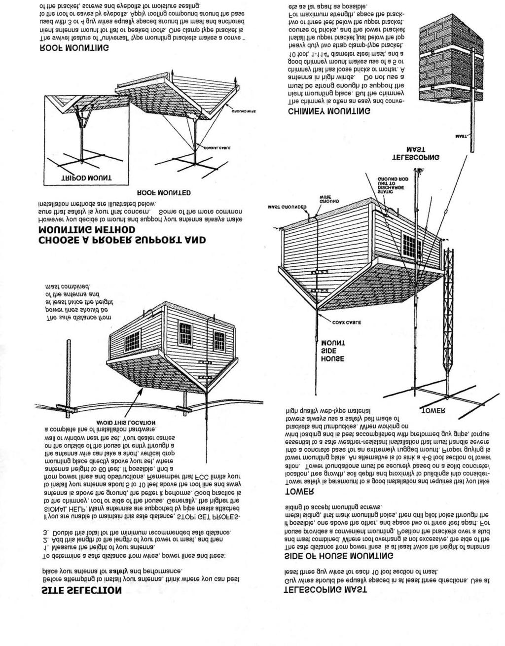
13 ( ) The smaller u-bolt should be on top and center between the two ¼-20 bolts in the mast. If the lower bolt contacts the bracket then rotate it around the mast until it clears. ( ) Tighten the (4) bolts that hold the antenna to the bracket. ( ) Place the (2) Larger U-bolt assemblies into the holes in the antenna mounting plate as shown in Figure I. Leave nuts loose until installation of the antenna. TASK IX Capacity Hat Assembly ( ) Refer to Figure J for assembly of the five Capacity Hats. ( ) Rotate the AV680 Coil Assembly (Ll) so the top end of the 17 meter stub is away from the AV680 Coil Strap as shown in Figure J. To rotate the coil assembly, loosen the lower coil hose clamp (HC 1). Tighten hose clamp when finished. ( ) Place (8) 6-32 x 3/8" screws (S1) and (8) 6-32 lock nuts (Ni) in each Counterpoise Ring assembly on the AV-680 Coil Assembly (LI). Leave the nuts loose so that the spokes can be slid between the rings. ( ) There are spokes of lengths 15", 25",36" and 48". Place the spokes in the ring assemblies as shown in Figure J. The shorter spokes will be on the bottom end of the coil and the longer spokes will be on the upper end of the coil. The 40" spokes are spares. Tighten all hardware on the ring assemblies. Slide the 1/8 inch rod caps onto each of the rods. Use caution when around the spokes, they will poke you easily. ( ) NOTE: For tuning 20, 30, 40, and 80 meters, the lengths of the spokes are adjusted as shown in Figure J. It is suggested that the spokes be installed at their initial lengths. If any of the bands are resonant too low in frequency, one of the corresponding spokes can be pruned. Only one spoke will require pruning but you may also prune the one on the opposite side to m aintain a balanced look to the spokes. Please refer to the Tuning section in figure J for more information. Installation The AV-680 antenna should be mounted at least 8 feet above ground. The main reason for this minimum height is safety. The AV-680 will work well at a minimum height of five feet but precautions from dangerous voltages must be taken. Always have help for the installation process. Do not attempt to install the antenna alone. Review the requirements for Antenna Location and safety precautions regarding Power Lines earlier in this manual. 13
14 The AV-680 may be roof mounted on a tripod or similar support. Keep the AV-680 base a minimum of 5 feet above the roof surface. This minimum dimension is the same for any roof material type. Attach a suitable ground wire to the support mast as mentioned in the Grounding section of this manual. Tuning The AV-680 should be checked with an VSWR meter before permanent installation to verify proper assembly and Matching Unit performance. Place the AV-680 at least 8 feet above ground and in as clear an area as possible. Connect the coax to the antenna base and test the VSWR using either an MFJ-259B VSWR Analyzer or equivalent or a transceiver and VSWR meter. The 2:1 VSWR Bandwidth should be referenced to determine performance. VSWR measurements made at the antenna base are the most accurate and may show a slightly narrower VSWR bandwidth than the specifications chart lists. Be sure to use very low power (less than 5 watts) when measuring VSWR at the antenna base. The AV-680 has few variables in its design. Therefore, VSWR should be very close to specifications. Each band can be adjusted individually. The element and stub lengths given in the drawings for the assembly of the antenna should tune the antenna close to the bottom of each band. Adjusting the stub lengths and trimming the capacity hats for each band will be needed to set the antenna your preferred section of the band. Tuning 20, 30 and 40 meters Individual adjustment of 20, 30, and 40 meters is accomplished by pruning one spoke in the corresponding capacity hat. Only one spoke needs to be adjusted and it does not matter which spoke is selected. Refer to Chart B to calculate the amount of spoke to prune and Figure J for spoke location. It is strongly suggested the AV-680 be assembled and tested with the spokes at the initial lengths to determine if any pruning is actually required. The initial length will tune the antenna to a frequency below each band. Trimming the spokes will cause the resonant frequency to go up. Trim a small amount each time and recheck. If you go too far and the resonant frequency is too high, make a longer spoke from one of the 40" spare spokes and try again. Tuning 80 meters 80 meters has an additional tapped loading coil that will allow for retuning the antenna after the spokes have been adjusted. For initial tuning, move the tap to the uppermost part of the coil so that all the turns are shorted out. Trim the spokes for the top of the band. Use the tapped loading coil to lower the operating frequency by moving the tap down. Set the antenna to the frequency you will be using the most. Use a Phillips screwdriver to secure the tap to the coil. Tuning 6, 10, 12, 15 and 17 meters Stub lengths can be adjusted for tuning the 6, 10, 12 & 17 meter bands. 15 meters usually will not require adjustment but can be adjusted by moving the loading coil on the main mast in and out of the main radiator. The total stub lengths are found in figure F. These values will tune the antenna to the lower part of the band. 14
15 Please note the length of coax will vary the VSWR on certain bands. Lengths less than 50 feet have stronger harmonic resonances than longer lengths. If a particular band will not properly resonate, try adding 3-5 feet or more of coax. Record the resonant frequencies with and without the added coax. There will be a change in resonant frequencies on one or more bands. RF loss at HF is not a major problem with RG8X or larger coax. There will be a minimal performance difference between a 50 ft. length and a 75 ft. length of coax. To lessen the possibility of RFI/TVI, roll up 6-8 turns of coax 8" inches diameter approximately one quarter wave (or multiple) from the base of the antenna. Use the quarter wave length of the frequency that causes the greatest amount of interference. Maintenance The AV-680 should be inspected mechanically at least once a year. Normal wear and tear varies significantly with climate. Anti-Oxidation paste such as NoAIOX or others can be applied to the radiator tubing sections. Use small amounts. Do not place the paste on the coax connector or inside of the Matching Unit. Inspect the inside of the Matching Unit on a regular basis. Remove dirt, bugs, or questionable material. Look for any degradation of parts. High voltage static discharges (lightning) may cause a failure to the small coil in the Matching Unit. This coil is a protection device. Make sure it is in good shape. Do not screw and unscrew the nylon insert nuts several times. If portable operation is desired, use stainless steel hardware without the nylon locking feature. Technical Assistance Technical assistance is available during normal business hours on weekdays. Hy-Gain is located in the Central Time Zone. Our hours are 8:00 AM till 4:00 PM CST Monday through Friday. Hy-Gain Telephone (662) Industrial Park Road FAX (662) Starkville, MS "hy-gain@hy-gain. com" Web Page " 15
16 Service history has shown that most problems are operating or installation errors, rather than equipment failures. Most problems can be resolved over the telephone. Please contact our staff before shipping parts or equipment to us. The packing material used to ship this antenna is designed to prevent shipping damage. Please reuse the original shipping carton if possible. Hy-Gain will not be responsible for shipping damage on returned items with improper packing. BAND Trimming Affect 80 Meters 10 KHz per inch 40 Meters 17 KHz per inch 30 Meters 50 KHz per inch 20 Meters 100 KHz per inch 17 Meters 60 KHz per ½ inch 15 Meters 100 KHz per inch 12 Meters 150 KHz per ½ inch 10 Meters 100 KHz per ½ inch 6 Meters 300 KHz per ½ inch CHART B Spoke Tuning 16
17 C2 1-1/2 X /8 X 69 EXPOSED LENGTH 1-1/48 X 69 EXPOSED LENGTH BD BC BB BF BE INSERT 3 INCHES Connect jumper to tube AV-680 L1 S8,N5 4 places IN Mount ring before tubing 1-1/2 X 12 BA 17 FIGURE A AV-680 Center Radiator Assembly
18 S3 SB1 N1 S1 A 6 Meter Stub Base Bracket SB1 BB RB Antenna Base RB N1 SB2 RB S1 N1 B 10&12 Meter Stub Base Bracket N1 RB Antenna Base SB2 S3 SB1 ALUMINUM RB N1 S1 C 17 Meter Stub Base Bracket and 6 Meter Stub Insulator SB1 S3 SB1 BB P3 BLACK PLASTIC N1 S1 Antenna Base N1 P3 RB RB FIGURE B Assembly of Stub Base Brackets 18
19 90 degree offset on this bracket C 17 Meter Stub Base Bracket and 6 Meter Stub Insulator 56 B 10&12 Meter Stub Base Bracket A 6 Meter Stub Base Bracket BA FIGURE C Installation of Stub Base Brackets 19
20 S1 D N1 90 Degree Stub Insulator N1 Antenna Base S3 P2 S1 E N1 RB Three Stub Insulator Antenna Base P3 N1 S3 S3 P3 RB N1 S1 F Single Stub Insulator Antenna Base P3 BB RB FIGURE D Installation of Stub Insulators N1 20


21 Align as shown. Keep corresponding holes in line. D E E F F All measurements measured to the TOP of each insulator. D 90 Degree Stub Insulators E Three Stub Insulators F Single Stub Insulators FIGURE E Installation of Stub Insulators 21
22 6 Meter stub 55-1/2 inches 10 Meter stub 102-1/2 inches 12 Meter stub 116 inches 17 Meter stub 161 inches CP E3 E1 5/16 x 6 3/8 x 44 3/8 x 55 E2 3/8 x 60 E1 E1 E1 E1 CP CP CP CP FIGURE F Stub Components This chart for reference when assembling the element stubs. Do not preassemble the elements. Assemble them on the antenna. The hose clamps will not pass through the insulators. Use the coupler at the top of each stub to make the element the total length given. This will tune the antenna to the bottom of the band. E3 CP E2 CP E2 CP E3 CP The coupler CP should be inserted about 3 inches into one tube and clamped. The other tube should be slid all the way till it contacts the other tube and clamped. The coupler at the end of the tube is used for final length adjustment. This will lower or raise the resonance frequency of the antenna.
23 Install the four base sections of the elements stubs A to the Aluminum mounting brackets. These are the 3/8 x 55 aluminum tubes with the threaded inserts in one end. Use the screw and the #10 lock washer to secure the tube to the bracket. Install one in each bracket shown. Thread the upper part of the tube through the insulator directly above it. 10 Meter Stub 17 Meter Stub 10 6 Meter Stub 12 Meter Stub FIGURE C Stub Base Brackets
24 6 meter 10 meter 12 meter 12 meter 55-1/ / FIGURE G Stub Installation 17 meter stub should be opposite of shorting bar on loading coil. 24
25 S6 (8 places) N1 (2 places) S5 (2 places) R1 (stainless ring with tabs) WL 72 stainless whip (7 places) install whips after matching box N3 One slot on the radial ring will be left empty. This empty slot will make room for the matching box assembly. Attach jumper from box to radial ring. Attach to ring with clamping screws. FIGURE H Conterpoise Assembly 25
26 Install the Antenna side first and tighten. You will not be able to access the nuts after the mast is installed. NB2 UB1 Top u-bolt will sit between these two bolts. Rotate bracket until bottom bolt does not interfere with mount. SB1 NB2 SW2 UB2 SB2 SW1 NB1 Parts NB2 4 X /16 x 18 nut SW2 4 X /16 split washer UB2 2 X /6 U-bolt SB2 2 X Steel saddle bracket FIGURE I Mounting Plate Assembly NB1 4 X /8 x 16 nut SW1 4 X /8 split washer UB1 2 X /8 u-bolt SB1 2 X AL saddle bar 26 MB 1 X Mast Bracket
27 80 meter spokes 48 x 8 Trim 80 meter spokes with tap at top of coil. Set to 4 MHZ or your highest operating point on 80. Use the tap on the coil to tune the antenna to your frequency of choice. 40 meter spokes 36 x 4 30 meter spokes 25 x 4 20 meter spokes 15 x 4 Adjust 15 meters by sliding this section in and out of the main mast. Move it up to lower the operating frequency. FIGURE J Spoke Assembly 27
28 S6 (8 places including 2 already mounted) Un-tighten the pre-installed screws and insert the rest of the screws and nuts loosely. Insert the spokes and tighten all eight screws. 1/8 AL spoke 48 (8 places) R2 (Aluminum ring without tabs) Pre-mounted N1 80 Meter Capacity Hat Ring S6 8 places. Loosely fit the screws and nuts into the ring. Insert the rods into the ring and tighten the screws. The rings are shown further apart than they are on the loading section for illustration only. You do not need to unbolt them from the tube. Install the tube caps on the tips of the rods. The caps can be removed for tuning if needed. 1/8 AL spoke cap N1 20,30,40 Meter Capacity Hat Rings 28
29 Notes 29
30 30
31 31
32 LIMITED WARRANTY hy-gain Warrants to the original owner of this product, if manufactured by hy-gain and purchased from an authorized dealer or directly from hy-gain to be free from defects in material and workmanship for a period of 12 months for rotator products and 24 months for antenna products from date of purchase provided the following terms of this warranty are satisfied. The purchaser must retain the dated proof-of-purchase (bill of sale, canceled check, credit card or money order receipt, etc.) describing the product to establish the validity of the warranty claim and submit the original or machine reproduction of such proof-of-purchase to hy-gain at the time of warranty service. hy-gain shall have the discretion to deny warranty without dated proof-of-purchase. Any evidence of alteration, erasure, or forgery shall be cause to void any and all warranty terms immediately. hy-gain agrees to repair or replace at hy-gain s option without charge to the original owner any defective product under warranty, provided the product is returned postage prepaid to hygain. Under no circumstances is hy-gain liable for consequential damages to person or property by the use of any hy-gain products. Out-of-warranty Service: hy-gain will repair any out-of-warranty product provided the unit is shipped prepaid. All repaired units will be shipped COD to the owner. Repair charges will be added to the COD fee unless other arrangements are made. This warranty is given in lieu of any other warranty expressed or implied. hy-gain reserves the right to make changes or improvements in design or manufacture without incurring any obligation to install such changes upon any of the products previously manufactured. All hy-gain products to be serviced in-warranty or out-of-warranty should be addressed to hygain, 308 Industrial Park Road, Starkville, Mississippi 39759, USA and must be accompanied by a letter describing the problem in detail along with a copy of your dated proof-of-purchase. This warranty gives you specific rights, and you may also have other rights which vary from state to state. 308 Industrial Park Rd. Starkville, MS REV A
INSTRUCTION MANUAL. Model 18AVQII Five Band Vertical Antenna 10, 15, 20, 40, 80 Meter. General Description. Theory of Operation
 Model 18AVQII Five Band Vertical Antenna 10, 15, 20, 40, 80 Meter 308 Industrial Park Road Starkville, MS 39759 (662) 323-9538 Fax: (662) 323-5803 INSTRUCTION MANUAL General Description The Hy-Gain 18AVQII
INSTRUCTION MANUAL. Model 18AVQII Five Band Vertical Antenna 10, 15, 20, 40, 80 Meter
 Model 18AVQII Five Band Vertical Antenna 10, 15, 20, 40, 80 Meter 308 Industrial Park Road Starkville, MS 39759 (662) 323-9538 Fax: (662) 323-5803 INSTRUCTION MANUAL General Description The Hy-Gain 18AVQII
INSTRUCTION MANUAL V-42R. Dual Band Collinear Gain Vertical for MHz and GENERAL DESCRIPTION
 308 Industrial Park Road, Starkville, MS 39759 USA Ph: (662) 323-9538 FAX: (662) 323-6551 V-42R Dual Band Collinear Gain Vertical for 144-148 MHz and 436-450 INSTRUCTION MANUAL GENERAL DESCRIPTION The
INSTRUCTION MANUAL. Specifications Electrical. Front-To-Back Ratio VSWR at Resonance Less than 1.5:1 Nominal Impedance. Mechanical
 300 Industrial Park Road, Starkville, MS 39759 Ph: (662) 323-8538 FAX: (662) 323-6551 TH-3JRS Tri-band HF 3 Elements Beam Covers 10, 15 and 20 Meters INSTRUCTION MANUAL WARNING Installation of this product
LJ element beam for 10 or 12 meters INSTRUCTION MANUAL. CAUTION: Read All Instructions Before Operating Equipment
 LJ-113 3 element beam for 10 or 1 meters INSTRUCTION MANUAL CAUTION: Read All Instructions Before Operating Equipment 308 Industrial Park Road Starkville, MS 39759 USA Tel: 66-33-9538 Fax: 66-33-6551 VERSION
MFJ-1799 INSTRUCTION MANUAL. 2,6,10,12,15,17,20,30,40,80 METER Vertical Antenna. CAUTION: Read All Instructions Before Operating Equipment
 MFJ-799,6,0,,5,7,0,30,40,80 METER Vertical Antenna INSTRUCTION MANUAL CAUTION: Read All Instructions Before Operating Equipment 300 Industrial Park Road Starkville, MS 39759 USA Tel: 66-33-5869 Fax: 66-33-655
MFJ-2389 Compact 8 Band Vertical
 MFJ-2389 Compact 8 Band Vertical The MFJ-2389 is an 8 band compact vertical that is designed to operate on 80, 40, 20, 15, 10, 6, 2M, and 70CM bands. The antenna will handle 200W PEP or 50W CW HF or 150W
INSTRUCTION MANUAL. Specifications Mechanical. 1 5/8 to 2 1/16 O.D. (41mm to 52mm)
") 308 Industrial Park Road Starkville, MS 39759 USA Ph: (662) 323-9538 FAX: (662) 323- General Description Model VB-25FM 2-Meter 5 Elements Beam INSTRUCTION MANUAL This antenna is a 5-element, 2-meter beam
308 Industrial Park Road Starkville, MS 39759 USA Ph: (662) 323-9538 FAX: (662) 323- General Description Model VB-25FM 2-Meter 5 Elements Beam INSTRUCTION MANUAL This antenna is a 5-element, 2-meter beam
Model VB-23FM 2-Meter 3-Element Beam
 308 Industrial Park Road Starkville, MS 39759 USA Ph: (662) 323-9538 FAX: (662) Model VB-23FM 2-Meter 3-Element Beam [ INSTRUCTION MANUAL Figure 1 Overall View and Boom Detail GENERAL DESCRIPTION This
MFJ-2100 INSTRUCTION MANUAL. CAUTION: Read All Instructions Before Operating Equipment
 MFJ-2100 INSTRUCTION MANUAL CAUTION: Read All Instructions Before Operating Equipment 300 Industrial Park Road Starkville, MS 39759 USA Tel: 662-323-5869 Fax: 662-323-6551 COPYRIGHT C 2015 MFJ Enterprises
The MFJ-1754 can be mounted on any 1" to 1 1/2" mast (conductive or non conductive.)
") INTRODUCTION: The MFJ-1754 is designed for use on the 2 meter and the 70 centimeter bands. On the 2 meter band the MFJ-1754 behaves as a vertical 1/4 wave antenna, however on 70 centimeter band the MFJ-1754
INTRODUCTION: The MFJ-1754 is designed for use on the 2 meter and the 70 centimeter bands. On the 2 meter band the MFJ-1754 behaves as a vertical 1/4 wave antenna, however on 70 centimeter band the MFJ-1754
MFJ-1750/1752 2M BASE ANTENNA with 5/8 GROUND PLANE Instruction Manual
 MFJ-1750/1752 2M BASE ANTENNA with 5/8 GROUND PLANE Thank you for purchasing the MFJ-1750/1752. The 1750 is a 5/8 wave antenna designed for operation on 144-148 MHz. The 1752 is designed to operate on
2014 MFJ ENTERPRISES, INC.
 Model MFJ-1907 INSTRUCTION MANUAL CAUTION: Read All Instructions Before Operating Equipment MFJ ENTERPRISES, INC. 300 Industrial Park Road Starkville, MS 39759 USA Tel: 662-323-5869 Fax: 662-323-6551 VERSION
INSTRUCTION MANUAL VB-66DX. 6-Meter 6-Element Beam. Preparation For Assembly. General Description
 VB-66DX 308 Industrial Park Road Starkville, MS 39759 USA Ph: (662) 323-9538 FAX: (662) 323-6551 6-Meter 6-Element Beam INSTRUCTION MANUAL General Description The Hy-Gain Model 66DX is a full sized 6-
MFJ-1835K34 40,30 METER ADD ON KIT FOR THE MFJ-1835 COBWEB ANTENNA INSTRUCTION MANUAL. CAUTION: Read All Instructions Before Operating Equipment
 MFJ-1835K34 40,30 METER ADD ON KIT FOR THE MFJ-1835 COBWEB ANTENNA INSTRUCTION MANUAL CAUTION: Read All Instructions Before Operating Equipment 300 Industrial Park Road Starkville, MS 39759 USA Tel: 662-323-5869
MFJ Instruction Manual Table of Contents
 Table of Contents MFJ-1768 Introduction...2 Choosing a Location for the Antenna...2 Tools and Time Requirements...3 MFJ-1768 Parts List...3 Safety Precautions...3 Assembly and Installation...4 Tuning...7
DB-2345 INSTRUCTION MANUAL. 308 Industrial Park Road Starkville, MS USA ph:(662) Fax: (662) Made in USA
 Fax: (662) Made in USA") 308 Industrial Park Road Starkville, MS 39759 USA ph:(662) 323-9538 Fax: (662) 323-5803 DB-2345 INSTRUCTION MANUAL Made in USA Hy-Gain DB2345 Dual-Band Beam INTRODUCTION The Hy-Gain DB2345 is a compact
308 Industrial Park Road Starkville, MS 39759 USA ph:(662) 323-9538 Fax: (662) 323-5803 DB-2345 INSTRUCTION MANUAL Made in USA Hy-Gain DB2345 Dual-Band Beam INTRODUCTION The Hy-Gain DB2345 is a compact
MFJ ENTERPRISES, INC.
 Model MFJ-2910 INSTRUCTION MANUAL CAUTION: Read All Instructions Before Operating Equipment MFJ ENTERPRISES, INC. 300 Industrial Park Road Starkville, MS 39759 USA Tel: 662-323-5869 Fax: 662-323-6551 VERSION
MFJ Instruction Manual
 MFJ-1763 Thank you for purchasing the MFJ-1763 portable beam antenna. This antenna is designed for operation throughout the 2-meter band. The MFJ-1763 is shipped partially assembled, you should have received
2006 MFJ ENTERPRISES, INC.
 Model MFJ-1796 INSTRUCTION MANUAL CAUTION: Read All Instructions Before Operating Equipment MFJ ENTERPRISES, INC. 300 Industrial Park Road Starkville, MS 39759 USA Tel: 662-323-5869 Fax: 662-323-6551 VERSION
INSTRUCTION MANUAL. Model BN-4000B. High Power Balun for Beams with Type SO-239. Construction. General Description. Mounting on Boom or Mast
 308 Industrial Park Starkville, MS 39759 USA Ph: (662) 323-9538 FAX: (662) 323 6551 Model BN-4000B High Power Balun for Beams with Type SO-239 INSTRUCTION MANUAL General Description The BN-4000 is a current-type
ASSEMBLY AND INSTALLATION INSTRUCTIONS R , 12, 15, 17, 20, 30, 40 Meters (5/99) COMMUNICATIONS ANTENNAS
 COMMUNICATIONS ANTENNAS") ASSEMBLY AND INSTALLATION INSTRUCTIONS R7000 10, 12, 15, 17, 20, 30, 40 Meters COMMUNICATIONS ANTENNAS 951465 (5/99) WARNING THIS ANTENNA IS AN ELECTRICAL CONDUCTOR. CONTACT WITH POWER LINES CAN RESULT
ASSEMBLY AND INSTALLATION INSTRUCTIONS R7000 10, 12, 15, 17, 20, 30, 40 Meters COMMUNICATIONS ANTENNAS 951465 (5/99) WARNING THIS ANTENNA IS AN ELECTRICAL CONDUCTOR. CONTACT WITH POWER LINES CAN RESULT
MFJ ENTERPRISES, INC.
 Model MFJ-2911 INSTRUCTION MANUAL CAUTION: Read All Instructions Before Operating Equipment MFJ ENTERPRISES, INC. 300 Industrial Park Road Starkville, MS 39759 USA Tel: 662-323-5869 Fax: 662-323-6551 VERSION
Directive Systems & Engineering 2702 Rodgers Terrace Haymarket, VA
 Directive Systems & Engineering 2702 Rodgers Terrace Haymarket, VA 20169 1628 www.directivesystems.com 703 754 3876 K1JX DESIGNED 6 ELEMENT 50 MHZ YAGI, DSEJX6 50 INTRODUCTION The Directive Systems DSEJX6-50
2006 MFJ ENTERPRISES, INC.
 WARC Bands Rotatable Mini-Dipole Model MFJ-1775W INSTRUCTION MANUAL CAUTION: Read All Instructions Before Operating Equipment MFJ ENTERPRISES, INC. 300 Industrial Park Road Starkville, MS 39759 USA Tel:
Installation Instructions Hustler 6-BTV Trap Vertical
 Installation Instructions Hustler 6-BTV Trap Vertical ASSEMBLY 1. Check the package contents against the parts list on page 2. 2. WARNING. Installation of this product near power lines is dangerous. For
MFJ-1886TR. Receive Loop Antenna INSTRUCTION MANUAL. CAUTION: Read All Instructions Before Operating Equipment
 MFJ-1886TR Receive Loop Antenna INSTRUCTION MANUAL CAUTION: Read All Instructions Before Operating Equipment 300 Industrial Park Road Starkville, MS 39759 USA Tel: 662-323-5869 Fax: 662-323-6551 COPYRIGHT
MQ-24SR Miniature Four band Hybrid Quad Antenna
 MQ-24SR Miniature Four band Hybrid Quad Antenna Most antennas are large heavy structures requiring heavy duty structures, rotors and lots of extra muscle during installation and lots of extra dollars before
INSTRUCTION MANUAL. DP-19PD 2-30 MHz Portable Dipole. Figure 1
 303 Industrial Park Road, Starkville, MS 39759 USA Ph: (662) 323-9533 FAX: (662) 323-6551 DP-19PD 2-30 MHz Portable Dipole INSTRUCTION MANUAL Figure 1 GENERAL DESCRIPTION The Model 19-PD is an ultra-light
Installation Instructions Hustler 6-BTV Trap Vertical
 Installation Instructions Hustler 6-BTV Trap Vertical ASSEMBLY 1. Check the package contents against the parts list on page 2. 2. WARNING. Installation of this product near power lines is dangerous. For
MFJ Foot Self-Supporting Vertical Antenna
 MFJ-2990 43-Foot Self-Supporting Vertical Antenna INTRODUCTION The MFJ-2990 is a 43-foot self-supporting vertical antenna that covers 160-6 meters with the use of an wide range antenna tuner. Because the
NOTE: This Drawing Is Not To Scale!
 NOTE: This Drawing Is Not To Scale! MFJ-1798 Vertical Antenna INTRODUCTION and THEORY OF DESIGN The MFJ-1798 is an 80 through 2 meter ground independent vertical antenna. This antenna has several unique
CP6A. 6 Band Trap Vertical 75-6m
 CP6A 6 Band Trap Vertical 75-6m Instruction Sheet The CP6A is a multi-band trap-vertical antenna for HF bands, covering the 75*, 40, 20, 15, 10m & 6m amateur bands. Made from heavy duty aluminum, the CP6A
MFJ ENTERPRISES, INC.
 Models: MFJ-1770C (10m) MFJ-1770B (15m) MFJ-1771B (17m) MFJ-1772B (20m) MFJ-1773B (30m) MFJ-1774B (40m) MFJ-1776B ( 6m) INSTRUCTION MANUAL CAUTION: Read All Instructions Before Operating Equipment MFJ
K1FO 12 ELEMENT 144/147 MHz YAGI
 K1FO 12 ELEMENT 144/147 MHz YAGI WARNING: INSTALLATION OF THIS PRODUCT NEAR POWER LINES IS DANGEROUS. FOR YOUR SAFETY FOLLOW THE INSTALLATION DIRECTIONS. Ariane Arrays, Inc. Copyright 2006 201 Hopedale
MFJ ENTERPRISES, INC.
 Model MFJ-2010 INSTRUCTION MANUAL CAUTION: Read All Instructions Before Operating Equipment MFJ ENTERPRISES, INC. 300 Industrial Park Road Starkville, MS 39759 USA Tel: 662-323-5869 Fax: 662-323-6551 VERSION
MFJ-1792/1793 Vertical Antenna
 MFJ-1792/1793 Vertical Antenna Table of Contents: Introduction... 1 Description... 1 Bandwidth, SWR, and Power Handling... 2 Choosing a Location for the Antenna... 3 Grounding... 3 Maintenance... 4 Tools
CP6 6 Band Trap Vertical 80-6m
 CP6 6 Band Trap Vertical 80-6m Instruction Sheet The CP6 is a multi-band trap-vertical antenna for HF bands, covering the 80*, 40, 20, 15, 10m & 6m amateur bands. Made from heavy duty aluminum, the CP6
TZ-RD-1740 Rotary Dipole Instruction Manual
 TZ-RD-1740 17/40m Rotary Dipole Instruction Manual The TZ-RD-1740 is a loaded dipole antenna for the 40m band and a full size rotary dipole for the 17m band. The antenna uses an aluminium radiating section
This file was downloaded from the website of G7SYW.
 This file was downloaded from the website of G7SYW http://www.g7syw.co.uk ASSEMBLY AND INSTALLATION INSTRUCTIONS Five-Band High-Performance Mini-Vertical Antenna 951495 (8/01) WARNING THIS ANTENNA IS AN
MFJ ENTERPRISES, INC.
 Model MFJ-2912 INSTRUCTION MANUAL CAUTION: Read All Instructions Before Operating Equipment MFJ ENTERPRISES, INC. 300 Industrial Park Road Starkville, MS 39759 USA Tel: 662-323-5869 Fax: 662-323-6551 VERSION
MFJ ENTERPRISES, INC.
 Model MFJ-2013 INSTRUCTION MANUAL CAUTION: Read All Instructions Before Operating Equipment MFJ ENTERPRISES, INC. 300 Industrial Park Road Starkville, MS 39759 USA Tel: 662-323-5869 Fax: 662-323-6551 VERSION
MFJ-2982 Feather-Lite 80-6 Meter Vertical Antenna
 MFJ-2982 Feather-Lite 80-6 Meter Vertical Introduction: The MFJ-2982 is a lightweight 31-foot fiberglass antenna designed to mount on any convenient post, mast, or a suitable wide-stance tripod such as
Introduction LOADING COIL COUNTERPOISE ATTACHMENT ANTENNA ATTACHMENT. Figure 1: MFJ-1625 Window/Balcony Mount Antenna
 Introduction MFJ-1625 The MFJ-1625 is a 200 Watt antenna tuner that was designed to provide portable or permanent HF communications on 80 through 10 meters and VHF on 6 meters. The universal mount design
TW4040. The Adventurer Monobander INSTRUCTION MANUAL. TransWorld Antennas
 TW4040 The Adventurer Monobander TransWorld Antennas INSTRUCTION MANUAL Contents 1 Limited Warranty 3 2 Important Safety Information 4 3 Specifications 3.1 Mechanical 4 3.2 Electrical 4 3.3 VSWR Performance
M2 Antenna Systems, Inc. Model No: KT31WARC
 M2 Antenna Systems, Inc. Model No: KT31WARC SPECIFICATIONS: Model... KT31WARC Frequency Range... 10.1-10.15 MHz **Selectable Frequency Range... 14.0-14.35 MHz **Selectable... (175 KHz / 2:1 VSWR Nominal)
2005 MFJ ENTERPRISES, INC.
 Model MFJ-9231 INSTRUCTION MANUAL CAUTION: Read All Instructions Before Operating Equipment MFJ ENTERPRISES, INC. 300 Industrial Park Road Starkville, MS 39759 USA Tel: 662-323-5869 Fax: 662-323-6551 VERSION
Cushcraft. Amateur Radio Antennas DB-46M8EL. Dual band 6 and 4 Meter, 8 Element Beam Antenna INSTRUCTION MANUAL
 Cushcraft Amateur Radio Antennas DB-46M8EL Dual band 6 and 4 Meter, 8 Element Beam Antenna INSTRUCTION MANUAL CAUTION: Read All Instructions Before Operating Equipment VERSION 1B Cushcraft Amateur Radio
INSTRUCTION MANUAL ORDER NO. V3R MODEL V3R. Collinear Gain Vertical for MHz
 ORDER NO. V3R MODEL V3R Collinear Gain Vertical for 216-225 MHz INSTRUCTION MANUAL General Description The new Hy-Gain V3R VHF antenna is a collinear 5/8-wave omnidirectional vertical antenna for the 216-225
MFJ-203 Bandswitched Dip Meter
 MFJ-203 Bandswitched Dip Meter Thank you for purchasing the MFJ-203 Bandswitched Dip Meter. The MFJ-203 Bandswitched Dip Meter is a solid state bandswitched adaptation of the traditional grid dip meter.
JK-65 Five Element 6M Yagi
 JK-65 Five Element 6M Yagi PO Box 266, Croton Falls, NY 10519-0266 845.228.8700 (TEL) 845.279.5526 (FAX) info@jkantennas.com Page 1 of 8 JK Antennas Limited Warranty and Liability JK Antennas ( Manufacturer
MA5B 20 / 17 / 15 / 12 / 10 Meter Beam Antenna
 ASSEMBLY AND INSTALLATION INSTRUCTIONS NE 20 / 17 / 15 / 12 / 10 Meter Beam Antenna 951485_GF_AB WARNING THIS ANTENNA IS AN ELECTRICAL CONDUCTOR. CONTACT WITH POWER LINES CAN RESULT IN DEATH, OR SERIOUS
Cushcraft. Amateur Radio Antennas LFA-6M5EL. 6 Meter 5 Element Loop Feed Antenna INSTRUCTION MANUAL
 Cushcraft Amateur Radio Antennas LFA-6M5EL 6 Meter 5 Element Loop Feed Antenna INSTRUCTION MANUAL CAUTION: Read All Instructions Before Operating Equipment VERSION 1A Cushcraft Amateur Radio Antennas 308
DB Duo-Monoband Beam 7 - Element, 12 and 17 Meter INSTRUCTION MANUAL. General Description
 308 Industrial Park Road Starkville, MS 39759 USA Ph: (662) 323-9538 FAX: (662) 323-6551 DB- 1217 Duo-Monoband Beam 7 - Element, 12 and 17 Meter INSTRUCTION MANUAL General Description The Hy-Gain DB-1217
INSTRUCTION MANUAL. Model VB-215DX MECHANICAL DESIGN GENERAL DESCRIPTION ELECTRICAL DESIGN. 2 Meter 15 Element Yagi for SSB/CW
 Model VB-215DX 2 Meter 15 Element Yagi for SSB/CW INSTRUCTION MANUAL GENERAL DESCRIPTION The Hy-Gain Model 215DX is a high performance yagi antenna for SSB/CW DXing in the Amateur 2 meter band. It features
Installation Instructions Hustler Collinear Two Meter Fixed Station Antenna Master Gainer Model G6-144B
 Installation Instructions Hustler Collinear Two Meter Fixed Station Antenna Master Gainer Model Warning INSTALLATION OF THIS PRODUCT NEAR POWER LINES IS DANGEROUS. FOR YOUR SAFETY, FOLLOW THE INSTALLATION
HFp. User s Guide. Vertical. entenna. 7 MHz 30 MHz Amateur Radio Antenna Plus 6-Meters
 User s Guide HFp Vertical 7 MHz 30 MHz Amateur Radio Antenna Plus 6-Meters The Ventenna Co. LLC P.O. Box 2998, Citrus Heights, CA, 956 www.ventenna.com entenna Table of Contents The HFp Antenna -------------------------------------------------------------------
ALWAYS ATTACH THE SAFETY ROPE TO A STABLE SUPPORT BEFORE ATTEMPTING TO ATTACH THE UNIVERSAL MOUNT TO A WINDOW FRAME OR RAIL.
 MFJ-1623 Introduction The MFJ-1623 was designed to provide portable or permanent HF communications on 30 through 10 meters and VHF on 6 meters. The universal mount design allows the user to install the
VC-300D VECTRONICS R. Digital Bar Graph Antenna Tuner. Owner's Manual. CAUTION: Read All Instructions Before Operating Equipment!
 VC-300D Digital Bar Graph Antenna Tuner CAUTION: Read All Instructions Before Operating Equipment! VECTRONICS R... the finest amateur radio products made 300 Industrial Park Road Starkville, MS 39759 (662)
JK M Hi-Q Coil Loaded Rotatable Dipole Version
 JK-401 40M Hi-Q Coil Loaded Rotatable Dipole 2018 Version 72 Grays Bridge Road, Unit D, Brookfield, CT 06804 845.228.8700 (TEL) 845.279.5526 (FAX) info@jkantennas.com LAST UPDATED: 02-01-2018 JK Antennas
Tarheel Antennas, Inc.
 Tarheel Antennas, Inc. Instruction Manual for the Model 300A Continuous Coverage HF Antenna PROUDLY MADE IN THE UNITED STATES OF AMERICA 18511 CR 304 St. Joseph, MO 64505 816-671-9409 / 816-364-2619 Fax
PACKING LIST MACO V-5000
 PACKING LIST MACO V-5000 PART QTY O.D. SIZE LENGTH DESCRIPTION CHECKLIST T47P 4 5/8.050 36 Aluminum Tubing _ T43P 1 7/8.050 48 Aluminum Tubing _ T18P 1 3/4.050 48 Aluminum Tubing _ T15P 1 5/8.050 48 Aluminum
MODEL DB-1015A 10- and 15-Meter Duo-Band Antenna Order No. 330
 MODEL DB-1015A 10- and 15-Meter Duo-Band Antenna Order No. 330 HY-GAIN ELECTRONICS CORPORATION 8601 Northeast Highway 6 Lincoln, Nebraska 68505 Telephone 464-9151 Area Code 402 TABLE OF CONTENTS page SECTION
PAC-12 Kit Contents. Tools Needed Soldering iron Phillips screwdriver Wire stripper Wrenches, 7/16 and 1/2 Terminal crimp tool Pliers Solder
 PAC-2 Kit Contents Part Quantity Screws: 8/32 x 3/8 Screws: 8-32 x 5/6 Screw: 8-32 x /4 #8 internal tooth washers #8 solder lug ring terminals Bolt: Aluminum, /4-20 x.5 /4 internal tooth washer Nut: Aluminum
ALWAYS ATTACH THE SAFETY ROPE TO A STABLE SUPPORT BEFORE ATTEMPTING TO ATTACH THE UNIVERSAL MOUNT TO A WINDOW FRAME OR RAIL.
 MFJ-1622 Introduction The MFJ-1622 Antenna was designed to provide portable or permanent HF communications on 40 through 10 meters and VHF on 6 and 2 meters. The universal mount design allows the user
Cisco Aironet 13.5-dBi Yagi Mast Mount Antenna (AIR-ANT1949)
") Cisco Aironet 13.5-dBi Yagi Mast Mount Antenna (AIR-ANT1949) Overview This document describes the 13.5-dBi Yagi mast mount antenna and provides instructions for mounting it. The antenna operates in the
Cisco Aironet 13.5-dBi Yagi Mast Mount Antenna (AIR-ANT1949) Overview This document describes the 13.5-dBi Yagi mast mount antenna and provides instructions for mounting it. The antenna operates in the
MFJ-66 Dip Meter Adapter
 MFJ-66 Dip Meter Adapter Thank you for purchasing the MFJ-66 Dip Meter Adapter. The MFJ-66 Dip Meter Adapter works with your MFJ-209/249/259 SWR Analyzer. The MFJ-66 Dip Meter Adapter is a kit consisting
MFJ Enterprises, Inc. 300 Industrial Park Rd Starkville, MS USA
 MFJ Enterprises, Inc. 300 Industrial Park Rd Starkville, MS 39759 USA MFJ-870 SWR & Power Meter Instruction Manual This SWR & Power meter is a highly accurate RF meter for measuring Forward Power, Reflected
RF Sense SDR Receiver TR Switch Model MFJ-1708B-SDR. RF Sense SDR Receiver TR Switch Model MFJ-1708B-SDR-S CTRL CTRL AUX AUX +12V +12V - + DELAY DELAY
 The MFJ-1708B-SDR and the MFJ-1708B-SDRS are RF sensed TR switches with a receive splitter designed to be used with a transceiver and a separate receiver such as the popular SDR receivers. The splitter
Directive Systems & Engineering 2702 Rodgers Terrace Haymarket, VA
 Directive Systems & Engineering 2702 Rodgers Terrace Haymarket, VA 20169-1628 www.directivesystems.com 703-754-3876 25 Element 7.4 wl. K1FO Designed Yagi, Model DSEFO432-25 ELECTRICAL SPECIFICATIONS Frequency
OMEGA. Communications Interface Cabinet. Antenna Installation Manual
 Ω OMEGA Communications Interface Cabinet Antenna Installation Manual 0049-0706-004 The products and programs described in this User s Guide are licensed products of Telenetics Corporation. This User s
2006 MFJ ENTERPRISES, INC.
 Model MFJ-207 INSTRUCTION MANUAL CAUTION: Read All Instructions Before Operating Equipment MFJ ENTERPRISES, INC. 300 Industrial Park Road Starkville, MS 39759 USA Tel: 662-323-5869 Fax: 662-323-6551 VERSION
MFJ-1846 Six-Band Hex-Beam Antenna
 MFJ-1846 Six-Band Hex-Beam Antenna Parts Inventory: As you unpack, please identify and check each part against the Master Parts List on the next page. This important step will familiarize you with the
M2 Antenna Systems, Inc. Model No: 2M4
 M2 Antenna Systems, Inc. Model No: 2M4 SPECIFICATIONS: Model... 2M4 Frequency Range... 144 To 148 MHz *Gain... 9.6 dbi Front to back... 20 db Typical Beamwidth... E=54 H=74 Feed type... T Match Feed Impedance....
M2 Antenna Systems, Inc. Model No: 2M7
 M2 Antenna Systems, Inc. Model No: 2M7 SPECIFICATIONS: Model... 2M7 Frequency Range... 144 To 148 MHz *Gain... 12.3 dbi Front to back... 20 db Typical Beamwidth... E=43 H=50 Feed type... T Match Feed Impedance....
C O R P O R A T I O N
 ASSEMBLY AND INSTALLATION INSTRUCTIONS A4S 20 / 5 / 0 MeterBeam C O R P O R A T I O N 95279 (8/98) WARNING THIS ANNNA IS AN ELECTRICAL CONDUCTOR. CONTACT WITH POWER LINES CAN RESULT IN DEATH, OR SERIOUS
EH-20 20m antenna. By VE3RGW
 EH-20 20m antenna By VE3RGW Equivalent circuit of EH-20 antenna system. Upper cylinder Lower cylinder Phasing coil Common mode radiator Tune coil RF choke or 14MHz trap 50ohm coaxial cable 0-150pF (case
MFJ ENTERPRISES, INC.
 Radio Interface Model MFJ-5124K/Y INSTRUCTION MANUAL CAUTION: Read All Instructions Before Operating Equipment! MFJ ENTERPRISES, INC. 300 Industrial Park Road Starkville, MS 39759 USA Tel: 662-323-5869
TELEX COMMUNICATIONS, INC ALDRICH LIVE SO. MINNEAPOLIS. MN U S A. /~g-~~~~r iu IORDER NO. 337s
 IkEfEX N TELEX COMMUNICATIONS, INC. 300 ALDRICH LIVE SO. MINNEAPOLIS. MN 55420 U S A /~g-~~~~r iu IORDER NO. 337s MAN A I MODEL V4S Collinear Gain Vertical for 420450 MHz PN801910 General Description The
MFJ SIGNAL ENHANCER II
 MFJ SIGNAL ENHANCER II Model MFJ-752D INSTRUCTION MANUAL CAUTION: Read All Instruction Before Operating Equipment MFJ ENTERPRISES, INC. P.O. BOX 494, MISSISSIPPI STATE, MS 39762, USA 925-0037D-752D-REV
2006 MFJ ENTERPRISES, INC.
 Model MFJ-4416B INSTRUCTION MANUAL CAUTION: Read All Instructions Before Operating Equipment MFJ ENTERPRISES, INC. 300 Industrial Park Road Starkville, MS 39759 USA Tel: 662-323-5869 Fax: 662-323-6551
Tarheel Antennas, Inc.
 Tarheel Antennas, Inc. Instruction Manual for the Model 100A-HP Continuous Coverage HF Antenna PROUDLY MADE IN THE UNITED STATES OF AMERICA 18511 CR 304 St. Joseph, MO 64505 816-671-9409 / 816-364-2619
2013 MFJ ENTERPRISES, INC.
 Model MFJ-868B MFJ Giant True Peak-Reading SWR/Wattmeter 1.8-60MHz MODEL MFJ-868B INSTRUCTION MANUAL CAUTION: Read All Instructions Before Operating Equipment MFJ ENTERPRISES, INC. 300 Industrial Park
M2 Antenna Systems, Inc. Model No: 20M6-125
 M2 Antenna Systems, Inc. Model No: 20M6-125 SPECIFICATIONS: Model... 20M6-125 Frequency Range... 14.0 14.350 MHz *Gain, (FS) / Over gnd... 11.19dBi / 16.6dBi @70 Front to back... 25 db Typical Beamwidth...
REP Design LLC. 193 Winding Ridge Rd, Southington, CT INSTALLATION INSTRUCTIONS:
 REP Design LLC 193 Winding Ridge Rd, Southington, CT 06489 1-860.426.1894 n7emw@cox.net www.repdesign.us INSTALLATION INSTRUCTIONS: SHD-SO239 Super Heavy Duty SO-239Antenna Mounting System Thank you for
Tilting Flat Panel Wall Mount Installation Guide
 Tilting Flat Panel Wall Mount Installation Guide Model: A580TM Easy installation Built-in level for easy positioning Safety bolts lock the TV on the mount Easy to adjust tilt angles: +5 to -15 degrees
60 Meter Mono-Band Conversion Kit for the DXE-MBVE-5A Multi-Band Vertical Antenna
 60 Meter Mono-Band Conversion Kit for the DXE-MBVE-5A Multi-Band Vertical Antenna DXE-MBVE-5A60MCK DXE-MBVE-5A60MCK-INS Revision 0a DX Engineering 2017 1200 Southeast Ave. - Tallmadge, OH 44278 USA Phone:
Yagi and Omni Antennas Installation Manual
 Yagi and Omni Antennas Installation Manual 25500445 Rev. A0 0218 Printed in U.S.A. Copyright 2018 Federal Signal Corporation Limited Warranty This product is subject to and covered by a limited warranty,
Cisco Aironet 2.4-GHz/5-GHz 8-dBi Directional Antenna (AIR-ANT2588P3M-N)
") Cisco Aironet.4-GHz/5-GHz 8-dBi Directional Antenna (AIR-ANT588P3M-N) This document outlines the specifications for the Cisco Aironet AIR-ANT588P3M-N.4/5-GHz 8-dBi 3-Port Directional Antenna with N-connectors
Cisco Aironet.4-GHz/5-GHz 8-dBi Directional Antenna (AIR-ANT588P3M-N) This document outlines the specifications for the Cisco Aironet AIR-ANT588P3M-N.4/5-GHz 8-dBi 3-Port Directional Antenna with N-connectors
M2 Antenna Systems, Inc. Model No: YAGI ANTENNA
 M Antenna Systems, Inc. Model No: 4.5-7 YAGI ANTENNA SPECIFICATIONS: Model... 4.5-7 Frequency Range... 4.0 To 4.5 MHz *Gain... 0 To 7 dbi Front to back... 0 db over the rear 80 Beamwidth... E=44 H=50 typical
2012 MFJ ENTERPRISES, INC.
 Model MFJ-9213 INSTRUCTION MANUAL CAUTION: Read All Instructions Before Operating Equipment MFJ ENTERPRISES, INC. 300 Industrial Park Road Starkville, MS 39759 USA Tel: 662-323-5869 Fax: 662-323-6551 VERSION
Cisco Aironet Omnidirectional Mast Mount Antenna (AIR-ANT2506)
") Cisco Aironet Omnidirectional Mast Mount Antenna (AIR-ANT2506) This document outlines the specifications, describes the omnidirectional mast mount antenna, and provides instructions for mounting it. Designed
Cisco Aironet Omnidirectional Mast Mount Antenna (AIR-ANT2506) This document outlines the specifications, describes the omnidirectional mast mount antenna, and provides instructions for mounting it. Designed
M2 Antenna Systems, Inc. Model No: 2M HO LOOP
 M2 Antenna Systems, Inc. Model No: 2M HO LOOP SPECIFICATIONS: Model... 2M HO LOOP Frequency Range... 144 To 144.5 MHz Gain, Typical @ 10 ft.... 4 dbd @ 10 deg. Gain, 2 STK @ 82 & 132... 8 dbd @ 9 deg.
Full Height Ladder Safety Gate
 Full Height Ladder Safety Gate Installation Instructions/Operation and Maintenance Manual Models Powder Coat Yellow (PCY) 304 Stainless Steel (SS) Hot Dipped Galvanized (GAL) Table of Contents Product
M2 Antenna Systems, Inc. Model No: 20M5LD
 M2 Antenna Systems, Inc. Model No: 20M5LD SPECIFICATIONS: Model... 20M5LD Frequency Range... 14.0 14.350 MHz *Gain (Full Band)... 10.2 dbi Typical Front to back... 23 db Typical Beamwidth... E=50 / H=66
The W3FF Portable Dipole
 The W3FF Portable Dipole This is the antenna I designed for my 'walking portable' station. It is a dipole constructed out of the plastic plumbing pipe CPVC. There are telescoping whips at the ends of each
AV-12AVQ Triband HF Vertical 10, 15, 20-Meter INSTRUCTION MANUAL
 308 Industrial Park Starkville, MS 39759 USA Ph: (662) 323-9538 FAX: (662) 323-6551 AV-12AVQ Triband HF Vertical 10, 15, 20-Meter INSTRUCTION MANUAL General Description This vertical antenna is designed
HFp. User s Guide. Vertical. entenna. 7 MHz 30 MHz Amateur Radio Antenna
 User s Guide HFp Vertical 7 MHz 30 MHz Amateur Radio Antenna The Ventenna Co. LLC P.O. Box 2998, Citrus Heights, CA, 95611 www.ventenna.com entenna Table of Contents The HFp Antenna -------------------------------------------------------------------
HFp. User s Guide. Vertical. entenna. 7 MHz 54 MHz Amateur Radio Antenna. The Ventenna Co. LLC P.O. Box 227 Huston, ID
 User s Guide HFp Vertical 7 MHz 54 MHz Amateur Radio Antenna The Ventenna Co. LLC P.O. Box 227 Huston, ID 83630 www.ventenna.com entenna Table of Contents The HFp Antenna -------------------------------------------------------------------
M2 Antenna Systems, Inc. Model No: 2M5WL
 M2 Antenna Systems, Inc. Model No: 2M5WL SPECIFICATIONS: Model... 2M5WL Frequency Range... 144 To 148 MHz *Gain... 16.84 dbi Front to back... 22 db Typical Beamwidth... E=26 H=29 Feed type... T Match Feed