DESIGN OF SINGLE PHASE H-BRIDGE MULTILEVEL INVERTER USING MICROCONTROLLER ATMEL 89C51
|
|
|
- Janis Bates
- 6 years ago
- Views:
Transcription
1 DESIGN OF SINGLE PHASE H-BRIDGE MULTILEVEL INVERTER USING MICROCONTROLLER ATMEL 89C51 A Project report submitted in partial fulfillment of the requirements for the Award of Degree of BACHELOR OF TECHNOLOGY IN ELECTRICAL AND ELECTRONICS ENGINEERING By CH. ASHLESHA (08241A0203) A.MOUNIKA B.APARNA N.SHARADA (08241A0224) (09245A0201) (09245A0205) Under the Esteemed Guidance of Mr. P.PRAVEEN KUMAR Assistant Professor Department of Electrical and Electronics Engineering GOKARAJU RANGARAJU INSTITUTE OF ENGINEERING & TECHNOLOGY, BACHUPALLY, HYDERABAD


2 GOKARAJU RANGARAJU INSTITUTE OF ENGINEERING & TECHNOLOGY BACHUPALLY, HYDERABAD CERTIFICATE This is to certify that the project report entitled DESIGN OF SINGLE PHASE H-BRIDGE MULTILEVEL INVERTER USING MICRO CONTROLLER ATMEL 89C51 that is being submitted by CH.ASHLESHA, ROLL.NO.08241A0203 A.MOUNIKA, B.APARNA, ROLL.NO.08241A0224, ROLL.NO.09245A0201, N.SHARADA, ROLL.NO.09245A0205, in partial fulfillment for the award of the Degree of Bachelor of technology in Electrical and Electronics Engineering to the Jawaharlal Nehru Technological University is a record of bonafide work carried out by them under my guidance and supervision. The results embodied in this project report have not been submitted to any another University or Institute for the award of any Degree or Diploma. External Guide HOD, EEE GRIET, Hyderabad. Internal Guide MR.P.PRAVEEN KUMAR Assist. Professor GRIET, HYDERABAD
3 ACKNOWLEDGEMENT This is to place on record our appreciation and deep gratitude to the persons without whose support this project would never seen the light of the day. We express our propound sense of gratitude to Mr. P.S. RAJU, Director, GRIET. For his guidance, encouragement, and for all facilities to complete this project. We also express my sincere thanks to Mr. P.M. SARMA, Head of the Department, Electrical and Electronics Engineering G.R.I.E.T for extending his help. We have immense pleasure in expressing thanks and deep sense of gratitude to my guide Mr. P.PRAVEEN KUMAR, Assist. Professor of Electrical and Electronic Engineering, G.R.I.E.T for his valuable suggestion and guidance throughout this project. Finally at the outset we would like to thank indirectly helped us accomplish our project successfully. all those who have directly or CH.ASHLESHA A.MOUNIKA B.APARNA N.SHARADA
4 ABSTRACT The power electronics device which converts DC power to AC power at required output voltage and frequency level is known as inverter. The voltage source inverters produce an output voltage or a current with levels either 0 or +ve or-ve V dc. They are known as two-level inverters. Multilevel inverter is to synthesize a near sinusoidal voltage from several levels of dc voltages. Multilevel inverter has advantage like minimum harmonic distortion. Multi-level inverters are emerging as the new breed of power converter options for high power applications. They typically synthesize the stair case voltage waveform (from several dc sources) which has reduced harmonic content. In this project work hardware model of Three-level single phase cascade H- Bridge inverter has been developed using MOSFETS. Gating signals for these MOSFETS have been generated by designing comparators. In order to maintain the different voltage levels at appropriate intervals, the conduction time intervals of MOSFETS have been maintained by controlling the pulse width of gating pulses ( by varying the reference signals magnitude of the comparator ). The results of hardware are compared with simulation results. Simulation models (designed in SIMULINK) have been developed up to five levels and THD in all the cases have been identified.
5 CONTENTS Chapter 1 INTRODUCTION 1.1 Outline of the thesis Chapter 2 MULTI-LEVEL INVERTERS TOPOLOGIES 2.1 Introduction 2.2 Types of Multi-level Inverters 2.3 Applications 2.4 Conclusions Chapter 3 SIMULATION OF MULTI -LEVEL INVERTERS 3.1 Introduction 3.2 Single phase H-bridge Inverters 3.3 Comparison with conventional systems Chapter 4 HARDWARE COMPONENTS 4.1 Introduction 4.2 Description of components Power MOSFETS NOT gate Comparator
6 Chapter 5 HARDWARE IMPLEMENTATION 5.1 Single H-Bridge 5.2 Cascade H-Bridge Positive cycle Negative cycle Complete waveform Chapter 6 CONCLUSIONS Future Scope of the Project REFERENCES APPENDIX
7 CHAPTER 1 INTRODUCTION In high power systems, the multilevel inverters can appropriately replace the existing system that uses traditional multi-pulse converters without the need of the transformers. All the three multi-level inverter topologies can be used in reactive power compensation without having the voltage unbalance problem. With the help of a transformer having one primary winding and several secondary windings, the cascade H- bridge configuration can be used in back-to-back intertie application. Also the structure of separate dc sources is well suited for various renewable energy sources such as fuel cell, photovoltaic, biomass etc. This structure is therefore well suited for an ac power supply in vehicle system utilities. The key features of a multi-level structure are as follows Harmonic content decreases as the number of levels increases thus Reducing the filtering requirements. Here switching losses can be avoided. (because of the absence of PWM techniques) Without an increase in the rating of an individual device, the output Voltage and power can be increased. The switching disservices do not encounter any voltage sharing problems. For this reason, multi-level inverters can easily be applied for high power applications such as large motor drivers and utility supplies. They have higher efficiency because the devices can be switched at Low frequency. Because of the key feature, they have become indispensable in high power and high voltage applications. 1.1 Outline of the thesis: Here a complete survey of the multi-level inverters is described. In chapter 2, the various topologies available are presented. Simulation of the cascade type inverter is done up to 5 level and the results of are shown in chapter 3. A detailed description of the components used in hardware implementation is done in chapter 4. In chapter 5, hardware implementation of single phase H-Bridge, cascade H- bridge inverter is described.
8 CHAPTER 2 MULTI-LEVEL INVERTERS TOPOLOGIES 2.1 Introduction The voltage source inverters produce a voltage or a current with levels either 0 or ±V dc they are known as two level inverters. To obtain a quality output voltage or a current waveform with a minimum amount of ripple content, they require high switching frequency along with various pulse width modulation (PWM) strategies. In high power and high voltage applications, these two level inverters, however, have some limitations in operating at high frequency mainly due to switching devices should be used in such a manner as to avoid problems associated with their series- parallel combinations that are necessary to obtain capability of handling high voltages and currents. It may be easier to produce a high power, high voltage inverter with the multilevel structure because of the way in which device voltage stresses are controlled in the structure. Increasing the number of voltage levels in the inverters without requiring higher ratings on the individual devices can increase the power rating. The unique structure of Multi-level voltages sources inverters allow them to reach high voltages with low harmonics without the use of transformer or series connected synchronized switching devices. As the number of voltage levels increases, the harmonic content of output voltage waveform decreases significantly. 2.2 Types of Multi-level Inverters The general structure of multi-level converter is to synthesize a near sinusoidal voltage from several levels of dc voltages, typically from capacitor voltage sources. As number of levels increases, the synthesized output waveform has more steps, which provides a staircase wave that approaches a desired waveform. Also, as steps are added to waveform, the harmonic distortion of the output wave decreases, approaching zero as the number of voltage levels increases. The Multi-level inverters can be classified into three types. Diode clamped Multi-level inverter Flying capacitor Multi-level inverter Cascade Multi-level inverter Diode- clamped Multi level inverter A diode clamped (m-level) inverter (DCMLI) typically consists of (m-1) capacitor on the dc bus and produces m levels on the phase voltages. Figure shows full bridge fivelevel diode clamped converter. The numbering order of the switches is Sa1, Sa2, Sa3, Sa4,
9 S a1, S a2, S a3, S a4. The dc bus voltage consists of four capacitors C1, C2, C3, and C4. For a dc voltage Vdc, the voltage across each capacitor is V dc/4, and each devices voltage stress is limited to one capacitor voltage level V dc/4 through clamping diodes. An m-level inverter leg requires (m-1) capacitors, 2(m-1) switching devices and (m-1) X(m-1) clamping diodes (a) Principle of operation To produce a stair case output, let us consider only one leg of five level inverter, as shown in Figure 2.1. A single phase bridge with one leg is shown in figure 2.1 The steps to synthesize the five level voltages are as follows a) Voltage level Van= V dc; turn on all upper switches S1, S2, S3 and S4. b) Voltage level Van= V dc/2, turn on the switches S2, S3, S4 and S1. c) Voltage level Van= 0, turn on the switches S3, S4, S1 and S2. d) Voltage level Van= - V dc/2 turn on the switches S4, S1, S2, S3. e) Voltage level Van= - V dc; turn on all lower switches S1, S2,S3 and S4.
10 2.2.1(b)Advantages: Fig 2.1 Single phase Diode clamped inverter a) When the number of levels is high enough, the harmonic content is Low enough to avoid the filters. b) Inverter efficiency is high because all devices are switching at the Fundamental frequency. c) The control method is simple (c)Disadvantages: a) Excessive clamping diodes are required when the number of levels is high. b) It is difficult to control the real power flow of the individual Converter in multi-level converter system.
11 2.2.2 Flying capacitor multilevel inverter: 2.2.2(a) Single phase flying capacitor inverter: The figure 2.2 shows a single phase full bridge 5-level inverter based on flying capacitors. Each phase like has an identical structure. Assuming that each capacitor has the same voltage rating, the series connection of the capacitors indicates the voltage level between calming points. All phase legs share the DC link capacitors C1 to C (b) Principle of operation: To produce a staircase output voltage, the switching instants of MOSFETS will be shown below. 1) Voltage level Van = Vdc/2, turn on all upper switches S1 - S4. 2) Voltage level Van = Vdc/4, there are three combinations. a) Turn on switches S1, S2, S3 and S1. (Van = Vdc/2 of upper C4 s - Vdc/4 of C1 s). b) Turn on switches S2, S3, S4 and S4. (Van = 3Vdc/4 of upper C3 s - Vdc/2 of C4 s). c) Turn on switches S1, S3, S4 and S3. (Van= Vdc/2 of upper C4 s 3Vdc/4 or C3 s + Vdc/2 of upper C2 ). 3) Voltage level Van= 0, turn on upper switches S3, S4, and lower switch S1, S2. 4) Voltage level Van= -Vdc/4, turn on upper switch S1 and lower switches S1, S2 and S3. 5) Voltage level Van= -Vdc/2, turn on all lower switches S1, S2, S3 and S4.
12 Fig 2.2 single phase flying capacitor inverter 2.2.2(c) Advantages: a) Large amount of storage capacitors can provide capabilities during Power outages. b) These inverters provide switch combination redundancy for Balancing different voltage levels. c) With the number of voltages levels increased, the harmonic content is low enough to avoid the filters. d) Both real and reactive power flow can be controlled.
13 2.2.2(d) Disadvantages: a) An excessive number of storage capacitors are required when the Number of levels is high. High-level inverters are more difficult to Package with the bulky power capacitors and expensive too. b) The inverter control can be very complicated and switching Frequency and switching losses are high for real power Transmission Cascaded Multi-level inverter: A relatively new converter structure called Cascaded Multi-level inverter, can avoid extra clamping diodes or voltage balancing capacitors. The converter topology used here is based on the series connection of single phase inverters with separate DC sources (a) The different topologies by with H-bridge are designed are: Cascade H-bridge Hybrid H-bridge Cascade H-bridge: Figure 2.3 shows the basic block of cascade H-bridge Multi-level inverter and its associated switching instants. As shown its consists of four power devices and a DC source. The switching states for four power devices are constant i.e., When S1 is on, S2 cannot be on and vice versa. Similarly with S3 and S4.
14 Fig 2.3 Block of a h-bridge Multi-level inverter Figure 2.4 shows the power circuit for one phase of multi level inverter. The resulting voltage ranges from +3Vdc to -3Vdc and the staircase are nearly sinusoidal, even without filtering Hybrid H-bridge: A hybrid H-bridge inverter consists of a series of H-bridge inverter units. The general function of this Multi-level inverter is to synthesize a desired voltage form several DC sources (SDCSs). Each SDCS is connected to an H-bridge inverter. The AC terminal voltages of different level inverters are connected in series. Unlike diode clamp or flying capacitors inverters the hybrid H-bridge inverter does not require any voltageclamping diodes or voltage-balancing capacitors.
15 Fig 2.4 Circuit diagram of 4-level cascade multi-level inverter Single phase Hybrid H-bride inverter: (a) Principle of operation: Figure 2.6 shows the synthesized phase voltage waveform of five-level hybrid H-bridge inverter with four SDCSs. The phase output voltage is synthesized by the sum of the four inverter outputs, Van = Va1+Va2+Va3+Va4. Each inverter circuit can generate three different outputs, +Vdc, 0, -Vdc, by connecting the dc source to the ac output side by different combinations of four GTOs, S1,S2, S3, S4. Turning on S1 and S4 yields Va4 = +Vdc. Turning on S2 and S3 yields Va4 = -Vdc. Bypassing the source yields Va4 = 0. Similarly ac output voltage at each level can be obtained in the same manner. The circuit connections of hybrid H-bridge and cascade H-bridge are same but the basic difference between them is that we can have only voltage source of same magnitude in cascade H-bridge whereas in hybrid h-bridge we can have voltage source of different magnitude in the hybrid H-bridge. Figure 2.5 shows a single phase leg of
16 the hybrid Multi-Level inverter. Figure 2.6 shows output waveform has the levels : ±4Vdc, ±3Vdc, ±2Vdc, ±1Vdc and 0. Fig 2.5 Hybrid H-Bridge inverter
 Advantages 1. Requires the least number of components among all multi-level Converter to achieve the same number voltage levels. 2.")
17 Five level H-bridge Inverter output waveform (b) Advantages 1. Requires the least number of components among all multi-level Converter to achieve the same number voltage levels. 2. Modularized circuit layout and packaging is possible because each Level has the structure, and there are no extra clamping diodes or Voltage balancing capacitors. 3. Soft switching can be used in this structure to avoid bulky and lossy resistor, capacitor, diode, snubbers (c) Disadvantages The limitation of h-bridge is the provision of the isolated power supply for each individual H-bridge cell. For applications, where, isolated power supply cannot be provided, the requirement of capacitors and complexity of its control increases as the number of voltage levels increases, which restricts its applications.
18 2.3 Applications: 1. Reactive power compensator When a Multi-level inverter draws pure reactive power, the phase voltage and current are 90 degrees apart, and the capacitor charge and discharge can be balanced. Such a converter, when serving for reactive power compensation is called Static Var Generator. The multi-level structure allows all the converter to be directly connected to a high voltage distribution or transmission system without the need of a step down transformer. All the three Multi level inverters can be used in reactive power compensation without having voltage unbalanced problem. 2. Back to Back intertie Inter connection of two Multi-level inverter with a DC link in between is called as a Back to back intertie. In this type of circuit the left hand side converter servers as rectifier, while the right hand side serves as the inverter. The purpose of the back to back intertie is to connect to synchronous systems of different frequencies. It can be treated as a) frequency connector b) phase shifter c) a power flow controller. 3. Utility compatible adjustable speed drives An ideal utility compatible adjustable speed drives requires unity power factor, negligible harmonics and high efficiency. By extended the back to back intertie, the multilevel inverter can be used for a utility compatible adjustable speed drive with the input as constant frequency AC source and the output has the variable frequency AC source. The major differences when using as a utility compatible adjustable speed drives and for back to back intertie, are the control design and size of capacitor. 2.4 CONCLUSION In this chapter design of multi-level inverter discussed in detail, relevant waveforms are presented and analyzed. From this analysis it can be concluded that multilevel inverters offer a low total harmonic distortion and high efficiency. Multi-level inverters are suitable for high voltages and high current application and also have higher efficiency because the devices can be switched at a lower frequency.
19 Introduction: CHAPTER 3 SIMULATION OF MULTI-LEVEL INVERTERS The multi-level inverter system is a very promising device in AC power drives when both reduced content and high power are required. Up to now several multilevel topologies have been introduced. The main topologies are diode clamped inverter, flying capacitor inverter, hybrid H-bridge inverter in order to generate a high voltage waveform using low voltage devices. In this chapter, we are considering the simulation of H- bridge inverters. Compared with diode clamped inverter and flying capacitor inverter, H- bridge inverters requires the least number of components to achieve the same number of voltage levels and H-bridge inverters does not require any extra clamping diodes or voltage balancing capacitors. Optimized circuit layout and packaging are possible in H- bridge multi-level inverter because each level has the same structure. The general structure of the H-bridge multi-level inverter is to synthesize a near sinusoidal voltage form several levels of DC voltages. As the number of levels are increased, the synthesize output waveform has more steps which produce a staircase wave that approaches the desired waveform. Also as the steps are added to the waveform the harmonic distortion of the output wave decreases. This can be observed from the figure following which are generated by simulating a single phase H-Bridge Multi level inverter and three phase H-Bridge Multilevel inverter using MATLAB SIMULINK.
20 3.2 Single Phase H-Bridge inverters Fig 3.1 Single Phase Full-Bridge inverter


21 Fig 3.2 Single Phase Full-Bridge Inverter output waveform Fig 3.3 Single Phase Full-Bridge Inverter Harmonic waveform
22 Fig 3.4 Single Phase three Level H-Bridge Inverter

23 Fig 3.5 Single Phase Three Level H-Bridge Inverter output wave form Fig3.6 Single Phase Three Level H-Bridge Inverter Harmonic
24 Fig 3.7 Single Phase four-level H-Bridge Inverter

25 Fig 3.8 Single Phase four level H-Bridge inverter Harmonic waveform Fig 3.9 Single Phase four level H-Bridge Inverter Harmonic waveform
26 Fig 3.10 Single Phase five level H-Bridge Inverter

27 Fig 3.11 Single phase five level H-bridge Inverter Harmonic waveform Fig 3.12 Single phase five level H-Bridge Inverter Harmonic Waveform
28 3.3 Comparison with conventional systems The 3 rd, 5 th, 7 th and 9 th harmonic ( normalized components ) of a H-Bridge Multilevel inverter for different number of levels are tabulated in table rd harmonic Content 5 th harmonic content 7 th harmonic content 9 th harmonic content Total Harmonic Distortion Single phase Full Bridge Single phase Three level Single phase Four level 4.318e e e e Single phase Five level From the above table we can observe that the harmonic content as well as the Total Harmonic Distortion (THD) factors gets reduced as the number of levels increased in a Single phase H-Bridge Multi-level inverter. This leads to a better and sinusoidal voltage waveform. We can also observe the great reduction of harmonic content in three-level H- Bridge inverter
29 CHAPTER 4 HARDWARE COMPONENTS 4.1 Introduction: Hardware implementation aims at cascading two single level inverters to obtain a three level inverter. The key components in the hardware implementation are: 1. Power MOSFETs 2. NOT Gate 3. IR 2110 Power MOSFETs are used as switching devices, NOT Gate is in a single level inverter to give signal to negative half inverse to that of the positive half and the IR 2110 is to give gating pulses of modulated pulse width and also for phase shifting. A brief description of the above components is given in the following section. 4.2 Description of the Components Power MOSFET Metal oxide semiconductor field effect transistor (MOSFET) is a power of transistor. The switching speed of the modern transistors is much higher than that of thyristors and are extensively employed in dc-dc and dc-ac converters. However, their voltage ratings and current ratings are lower than those of thyristors and are used in low to medium-power applications. A power MOSFET is a voltage-controlled device and requires only a small input current. The switching speed is very high and the switching times are of the order of nanoseconds. As the MOSFETs conduct in the duration for which the gate pulse is present and it doesn t conduct when the gate pulse is removed, there is no need for an external commutation circuitry. Power MOSFETs find increasing applications in low-power high frequency converters. The input impendence is very high, 10^9 to 10^11 ohms. They require very low low gate energy and low switching and low conduction losses. However MOSFETs have the problem of electrostatic discharge and also its difficult to protect them under short circuited fault conditions. The two types of MOSFETs are 1. Depletion MOSFETs, and 2. Enhancement MOSFETs.

30 A depletion type MOSFET remains on at zero gate voltage where as an enhancement type of MOSFET remains off at zero gate voltage, the enhancement type MOSFETs are generally used as switching devices in power electronics. In this project we have used n-channel enhancement MOSFETs. Choice of MOSFETs over other power transistors: The other types of power transistors are BJTs (Bipolar Junction Transistors), SITs (static induction transistors), IGBTs (insulated gate bipolar transistors) and COULUMBS. MOSFETs do not have the problem of second breakdown phenomena as do BJT. A BJT is a current-controlled device and its current gain is highly dependent on the junction temperature. The high on-state drops in SITs limit its applications for general power conversions. The switching speed of IGBTs is inferior to that of MOSFETs. IGBTs are costlier than the MOSFETs. COULUMBS is a new technology for high voltage power MOSFETs, expect for switching losses (same as the conventional MOSFETs) COULUMBS is advanced and improved version of power MOSFET. Our hardware implementation is limited to three level inverters which doesn t need COULUMBS technology which is much costlier than MOSFETs. PIN DIAGRAM OF A MOSFET A practical MOSFET consists of three pins namely G-gate, D-drain, and S-source. Gate signal is a given between G and S. Supply is a given between D and S. it s called the common source connection.
31 MOSFET symbol NOT Gate The NOT Gate performs a basic logic function called inversion or complementation. The purpose of the gate is to change one logic level to opposite logic level. it has one input and one output, when high level is applied as an input low level will appear at output and vice versa. NOT GATE SYMBOL NOT GATE TRUTH TABLE S. No A X= -A The NOT gate has been used in the project to provide inversed gate signal to the negative half of single level inverter in its hardware implementation.
32 NOT GATE PIN DIAGRAM NOT GATE OUTPUT WAVEFORM IR2110 The IR2110 IC s is floating channel designed for bootstrap operation. It is a high voltage, high speed power. MOSFET and IGBT drive with independent high and low side referenced output channels.
33 CHAPTER 5 HARDWARE IMPLEMENTATION In this unit I discuss in detail about the hardware implementation of single h-bridge and cascaded h-bridge. The cascaded h-bridge model is used for obtaining the three level because of the advantages over the other two designs as discussed before. we also present the pictures of the waveforms obtained. The basic idea of getting the stepped waveform is to connect the desired number of sources(in series) across the load at a particular instant through fast switching devices i.e, to get a voltage level of 5Vs, we connect five voltage sources in series across the load. The next instant we need a lesser voltage level (say 4Vs), one of the sources is eliminated from the circuitry using the switching devices. So we have only four sources connected in series across the load. Hence we make use of these fast switching devices to connect or disconnect a particular source across the load. The basic idea of controlling the output voltage magnitude of inverter by using microcontroller technique is, changing the width of pulses by varying a magnitude of reference wave. Here we first present the h-bridge (single level), cascaded h-bridge(3 levels) and go on to the microcontroller. In the process we made use of IR2110 and NOT gate whose operations are discussed in previous chapters. MULTILEVEL INVERTER IMPLEMENTATION 5.1 Single H-bridge For obtaining single level, MOSFETs are connected as shoe in the figure. Here MOSFETs are shown as switches and are numbered for easy understanding. The applied source is a low voltage DC supply (say 15V) and the load may be a resistive one (10000 ohms).
34 Single H- Bridge The expected voltage across the load and the gating signals for the MOSFETs are as shown. MOSFETs conduct for the duration its gate pulse is present and is commutated as soon as the pulse is removed. So we do not need any extra commutating circuitry. The duration for which the gating signal b has to be given for a particular MOSFET is shown in shaded portion
35 During the first half cycle i.e., during which the MOSFETs 1&2 are fired voltage, across the output is positive and the equivalent circuit is as shown.(the MOSFET s which are not conducting during interval are not shown). During the other half cycle i.e., during which MOSFETs 3&4 conducts, voltage across the load is negative (opposite to that assumed) and the equivalent circuit is as shown

36 Now to practically obtain such a gating signals we make use of NOT gate IC whose operation is discussed before. MOSFET s 1&2 are fired from function generator and MOSFETs 3&4 are fired from the NOT gate whose input is taken from the same function generator which IC s used to fire the MOSFETs 1&2. When a 10V voltage source and a resistive load of ohms is applied to the h-bridge the following waveform is observed in CRO, which is connected across the load. The entire block diagram is as shown. In the block diagram the waveform obtained is shown at the load terminal.
37 5.2 Cascaded H-bridge By cascading two single h-bridges, we can get a three level inverter with levels 2Vs, Vs and 0. The circuit diagram of the cascaded configuration is as shown. The MOSFETs in the upper bridge are numbered 1,2,3 & 4 where as that of the lower bridge 1, 2, 3 & 4. In obtaining 3-levels, we individually obtain the positive and negative cycles and by cascading the two cycles we can get the 3-level stepped waveform.
38 5.2.1 Positive cycle For obtaining positive half cycle, we need to get +Vs, +2Vs and 0s. The expected wave form is as shown. To obtain a voltage level of Vs at the load, only one the sources has to be connected to the load. For that we trigger MOSFETs 1,2 in one bridge and MOSFETs 2 and 4 in the other. this ensures only the source in the upper bridge to be connected across the load and equivalent circuit as shown.
39 For 2Vs,both the sources are to be connected in series across the load. this condition can be obtained by firing MOSFETs 1,2,1 and 2.the circuit condition is as shown. Therefore the MOSFETs which are to be triggered during a particular instant in order to obtain the required waveform are shown shaded portion in the figure.
40 Such gating signals can be obtained by making use of IR2110.firing pulses of amplitude 8Vand frequency 100hz obtained from the function generator are used to trigger MOSFETs 1,2and 2.the other MOSFETs 1 and 4 can be fired with pulses from IR2110.sinusoidal signal (of amplitude 10V)whose frequency is same as that of the function generator used before(i.e.,100hz)is being to the IR2110.IR2110 is being fed by a dc source whose amplitude is less than that of the sinusoidal signal. the output of IR2110 is given to the gate of MOSFET 1 and ground of IR2110 being given to gate of 4.the block diagram showing the connection as shown below. the output obtained is viewed in the CRO and is as shown at the load terminals in the block diagram.
41 Negative cycle Negative cycle can be obtained similar to that of the positive half cycle. Here we need to get the voltage levels of Vs,-2Vs and 0.the expected waveform is as shown.
42

43 Similarly for obtaining a voltage level of -2Vs, MOSFETs 3, 4, 3 and4 are to fired and the circuitry during this interval is as shown. The MOSFETs which are to be conducting during a particular instant is shown by shaded region below.
44 Complete waveform The instants at which the MOSFETs are to be fired for obtaining the complete Waveform is as shown in the figure below
45


46 HARDWARE DESIGN: OUTPUT WAVE FORM:
47 CHAPTER 9 CONCLUSIONS We hereby conclude that Multi-level inverters is a very promising technology in the power industry. In this project, the advantages and applications of Multi-Level Inverters are mentioned and a detailed description of different multi-level inverter topologies is presented. Single Phase H-Bridge Inverter & Three Phase H-Bridge Inverters functioning is realized virtually using MATLAB SIMULINK. A detailed Multi-Level Inverter is presented from which we concluded that the harmonic content is greatly reduced in Multi-Level Inverter. A single phase Cascade H-Bridge Inverter is designed and implemented practically. The components used in the practical implementation of H-Bridge Inverter are described in detail. Future scope of the project This project can be extended further by increasing the number of levels in multilevel inverter. IC s can be used to generate gating pulses directly rather than designing them by using comparators and NOT gates. By using IC s, complexity in designing gate pulses can be reduced.
48 Reference [1] Power Electronics Circuits, Devices & Applications, Muhammad H. Rashid, Third Edition, Prentice Hall India. [2] Linear Integrated Circuits, D.roy Choudary, Shail B.Jain, Second Edition, New Age International Publishers. [3] Multi-level Converter-A New Breed of Power Converters, Jih-Sheng Lai and Fang Zheng Peng, IEEE Trans. Ind, Applicant Vol.32 [4] Opamps & Linear Integrated Circuits, Ramakanth Gayakward, PHI Publications. [5] Power Electronic for Technology, Ashfaq Ahmed, PEARSON Education.

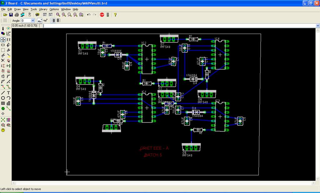
49 APPENDIX A SOFTWARE USED EAGLE EAGLE is an EDA program by Cad soft for creating printed circuit boards. The name is an acronym formed Easy Applicable Graphical Layout Editor. Cad soft Eagle and the company in September 2009, Premier Farnell sells, s supplier of electronic components.[1] The software consists of several components: Layout Editor, Schematic Editor, Auto router and an extensible components database. It is for the platforms Microsoft windows, Linux and Mac OS X available. It exists for non-commercial use, a free version on a schematic sheet, half Euro card num 80 mm and two signal layers is limited to 100.The schematic editor can be used by a special component library for programming a Micro SPS be used.
50
51 APPENDIX B
52 APPENDIX C
COMPARATIVE STUDY OF DIFFERENT TOPOLOGIES OF FIVE LEVEL INVERTER FOR HARMONICS REDUCTION
 COMPARATIVE STUDY OF DIFFERENT TOPOLOGIES OF FIVE LEVEL INVERTER FOR HARMONICS REDUCTION Mahtab Alam 1, Mr. Jitendra Kumar Garg 2 1 Student, M.Tech, 2 Associate Prof., Department of Electrical & Electronics
CHAPTER 4 MULTI-LEVEL INVERTER BASED DVR SYSTEM
 64 CHAPTER 4 MULTI-LEVEL INVERTER BASED DVR SYSTEM 4.1 INTRODUCTION Power electronic devices contribute an important part of harmonics in all kind of applications, such as power rectifiers, thyristor converters
Simulation of Three Phase Cascaded H Bridge Inverter for Power Conditioning Using Solar Photovoltaic System
 Simulation of Three Phase Cascaded H Bridge Inverter for Power Conditioning Using Solar Photovoltaic System 1 G.Balasundaram, 2 Dr.S.Arumugam, 3 C.Dinakaran 1 Research Scholar - Department of EEE, St.
Harmonic Reduction in Induction Motor: Multilevel Inverter
 International Journal of Multidisciplinary and Current Research Research Article ISSN: 2321-3124 Available at: http://ijmcr.com Harmonic Reduction in Induction Motor: Multilevel Inverter D. Suganyadevi,
MATLAB Implementation of a Various Topologies of Multilevel Inverter with Improved THD
 2016 IJSRSET Volume 2 Issue 3 Print ISSN : 2395-1990 Online ISSN : 2394-4099 Themed Section: Engineering and Technology MATLAB Implementation of a Various Topologies of Multilevel Inverter with Improved
Bhanutej Jawabu Naveez Assistant Professor, Vignana Bharathi Institute of Technology, Aushapur, Ghatkesar, Hyderabad.
 Performance Analysis of Three Phase Five-Level Inverters Using Multi-Carrier PWM Technique Bhanutej Jawabu Naveez Assistant Professor, Vignana Bharathi Institute of Technology, Aushapur, Ghatkesar, Hyderabad.
Speed control of Induction Motor drive using five level Multilevel inverter
 Speed control of Induction Motor drive using five level Multilevel inverter Siddayya hiremath 1, Dr. Basavaraj Amarapur 2 [1,2] Dept of Electrical & Electronics Engg,Poojya Doddappa Appa college of Engg,
Simulation and Experimental Results of 7-Level Inverter System
 Research Journal of Applied Sciences, Engineering and Technology 3(): 88-95, 0 ISSN: 040-7467 Maxwell Scientific Organization, 0 Received: November 3, 00 Accepted: January 0, 0 Published: February 0, 0
A Comparative Study of Different Topologies of Multilevel Inverters
 A Comparative Study of Different Topologies of Multilevel Inverters Jainy Bhatnagar 1, Vikramaditya Dave 2 1 Department of Electrical Engineering, CTAE (India) 2 Department of Electrical Engineering, CTAE
A Modified Cascaded H-Bridge Multilevel Inverter topology with Reduced Number of Power Electronic Switching Components
 International Journal of Electrical Engineering. ISSN 0974-2158 Volume 6, Number 2 (2013), pp. 137-149 International Research Publication House http://www.irphouse.com A Modified Cascaded H-Bridge Multilevel
Australian Journal of Basic and Applied Sciences. Simulation and Analysis of Closed loop Control of Multilevel Inverter fed AC Drives
 AENSI Journals Australian Journal of Basic and Applied Sciences ISSN:1991-8178 Journal home page: www.ajbasweb.com Simulation and Analysis of Closed loop Control of Multilevel Inverter fed AC Drives 1
A NOVEL APPROACH TO ENHANCE THE POWER QUALITY USING CMLI BASED CUSTOM POWER DEVICES
 A NOVEL APPROACH TO ENHANCE THE POWER QUALITY USING CMLI BASED CUSTOM POWER DEVICES 1 M. KAVITHA, 2 A. SREEKANTH REDDY & 3 D. MOHAN REDDY Department of Computational Engineering, RGUKT, RK Valley, Kadapa
PF and THD Measurement for Power Electronic Converter
 PF and THD Measurement for Power Electronic Converter Mr.V.M.Deshmukh, Ms.V.L.Jadhav Department name: E&TC, E&TC, And Position: Assistant Professor, Lecturer Email: deshvm123@yahoo.co.in, vandanajadhav19jan@gmail.com
Simulation of Cascade H-Bridge Multilevel Inverter With Equal DC Voltage Source
 Simulation of Cascade H-Bridge Multilevel Inverter With Equal DC Voltage Source Ramakant Shukla 1, Rahul Agrawal 2 PG Student [Power electronics], Dept. of EEE, VITS, Indore, Madhya pradesh, India 1 Assistant
Simulation & Implementation Of Three Phase Induction Motor On Single Phase By Using PWM Techniques
 Simulation & Implementation Of Three Phase Induction Motor On Single Phase By Using PWM Techniques Ashwini Kadam 1,A.N.Shaikh 2 1 Student, Department of Electronics Engineering, BAMUniversity,akadam572@gmail.com,9960158714
Low Order Harmonic Reduction of Three Phase Multilevel Inverter
 Journal of Scientific & Industrial Research Vol. 73, March 014, pp. 168-17 Low Order Harmonic Reduction of Three Phase Multilevel Inverter A. Maheswari 1 and I. Gnanambal 1 Department of EEE, K.S.R College
CAPACITOR VOLTAGE BALANCING IN SINGLE PHASE SEVEN-LEVEL PWM INVERTER
 Journal of Research in Engineering and Applied Sciences CAPACITOR VOLTAGE BALANCING IN SINGLE PHASE SEVEN-LEVEL PWM INVERTER Midhun G, 2Aleena T Mathew Assistant Professor, Department of EEE, PG Student
Analysis Of Seven Level Asymmetric Cascaded H-Bridge Inverter
 Analysis Of Seven Level Asymmetric Cascaded H-Bridge Inverter 1 M. Manga lakshmi, 2 G.D.Sairam vihari, 3 T.Venkata parasuram 1 Assistant Professor, 2,3 B.Tech student Department of EEE, Pragati Engineering
International Journal of Advance Engineering and Research Development
 Scientific Journal of Impact Factor(SJIF): 3.134 e-issn(o): 2348-4470 p-issn(p): 2348-6406 International Journal of Advance Engineering and Research Development Volume 2,Issue 4, April -2015 Reduction
Cascaded Connection of Single-Phase & Three-Phase Multilevel Bridge Type Inverter
 Cascaded Connection of Single-Phase & Three-Phase Multilevel Bridge Type Inverter Mukesh Kumar Sharma 1 Ram Swaroop 2 Mukesh Kumar Kuldeep 3 1 PG Scholar 2 Assistant Professor 3 PG Scholar SIET, SIKAR
Speed Control of Induction Motor using Multilevel Inverter
 Speed Control of Induction Motor using Multilevel Inverter 1 Arya Shibu, 2 Haritha S, 3 Renu Rajan 1, 2, 3 Amrita School of Engineering, EEE Department, Amritapuri, Kollam, India Abstract: Multilevel converters
DOWNLOAD PDF POWER ELECTRONICS DEVICES DRIVERS AND APPLICATIONS
 Chapter 1 : Power Electronics Devices, Drivers, Applications, and Passive theinnatdunvilla.com - Google D Download Power Electronics: Devices, Drivers and Applications By B.W. Williams - Provides a wide
Multilevel Inverter for Single Phase System with Reduced Number of Switches
 IOSR Journal of Electrical and Electronics Engineering (IOSR-JEEE) e-issn: 2278-1676 Volume 4, Issue 3 (Jan. - Feb. 2013), PP 49-57 Multilevel Inverter for Single Phase System with Reduced Number of Switches
A NOVEL SWITCHING PATTERN OF CASCADED MULTILEVEL INVERTERS FED BLDC DRIVE USING DIFFERENT MODULATION SCHEMES
 International Journal of Electrical and Electronics Engineering Research (IJEEER) ISSN(P): 2250-155X; ISSN(E): 2278-943X Vol. 3, Issue 5, Dec 2013, 243-252 TJPRC Pvt. Ltd. A NOVEL SWITCHING PATTERN OF
Development of Multilevel Inverters for Control Applications
 International Research Journal of Engineering and Technology (IRJET) e-issn: 2395-56 Volume: 3 Issue: 1 Jan-216 www.irjet.net p-issn: 2395-72 Development of Multilevel Inverters for Control Applications
Modified Multilevel Inverter Topology for Driving a Single Phase Induction Motor
 Modified Multilevel Inverter Topology for Driving a Single Phase Induction Motor Divya Subramanian 1, Rebiya Rasheed 2 M.Tech Student, Federal Institute of Science And Technology, Ernakulam, Kerala, India
A Hybrid Cascaded Multilevel Inverter for Interfacing with Renewable Energy Resources
 A Hybrid Cascaded Multilevel Inverter for Interfacing with Renewable Energy Resources P.Umapathi Reddy 1, S.Sivanaga Raju 2 Professor, Dept. of EEE, Sree Vidyanikethan Engineering College, Tirupati, A.P.
A COMPARITIVE STUDY OF THREE LEVEL INVERTER USING VARIOUS TOPOLOGIES
 A COMPARITIVE STUDY OF THREE LEVEL INVERTER USING VARIOUS TOPOLOGIES Swathy C S 1, Jincy Mariam James 2 and Sherin Rachel chacko 3 1 Assistant Professor, Dept. of EEE, Sree Buddha College of Engineering
CHAPTER 3 SINGLE SOURCE MULTILEVEL INVERTER
 42 CHAPTER 3 SINGLE SOURCE MULTILEVEL INVERTER 3.1 INTRODUCTION The concept of multilevel inverter control has opened a new avenue that induction motors can be controlled to achieve dynamic performance
Enhanced Performance of Multilevel Inverter Fed Induction Motor Drive
 Enhanced Performance of Multilevel Inverter Fed Induction Motor Drive Venkata Anil Babu Polisetty 1, B.R.Narendra 2 PG Student [PE], Dept. of EEE, DVR. & Dr.H.S.MIC College of Technology, AP, India 1 Associate
A Novel Cascaded Multilevel Inverter Using A Single DC Source
 A Novel Cascaded Multilevel Inverter Using A Single DC Source Nimmy Charles 1, Femy P.H 2 P.G. Student, Department of EEE, KMEA Engineering College, Cochin, Kerala, India 1 Associate Professor, Department
Multilevel Inverters : Comparison of Various Topologies and its Simulation
 2017 IJSRST Volume 3 Issue 2 Print ISSN: 2395-6011 Online ISSN: 2395-602X National Conference on Advances in Engineering and Applied Science (NCAEAS) 16 th February 2017 In association with International
Analysis of Asymmetrical Cascaded 7 Level and 9 Level Multilevel Inverter Design for Asynchronous Motor
 Analysis of Asymmetrical Cascaded 7 Level and 9 Level Multilevel Inverter Design for Asynchronous Motor Nayna Bhargava Dept. of Electrical Engineering SATI, Vidisha Madhya Pradesh, India Sanjeev Gupta
A New Transistor Clamped 5-Level H-Bridge Multilevel Inverter with voltage Boosting Capacity
 A New Transistor Clamped 5-Level H-Bridge Multilevel Inverter with voltage Boosting Capacity Prakash Singh, Dept. of Electrical & Electronics Engineering Oriental Institute of Science & Technology Bhopal,
Implementation of New Three Phase Modular Multilevel Inverter for Renewable Energy Applications
 IOSR Journal of Electrical and Electronics Engineering (IOSR-JEEE) e-issn: 2278-1676,p-ISSN: 2320-3331, Volume 12, Issue 3 Ver. II (May June 2017), PP 130-136 www.iosrjournals.org Implementation of New
CHAPTER 4 MODIFIED H- BRIDGE MULTILEVEL INVERTER USING MPD-SPWM TECHNIQUE
 58 CHAPTER 4 MODIFIED H- BRIDGE MULTILEVEL INVERTER USING MPD-SPWM TECHNIQUE 4.1 INTRODUCTION Conventional voltage source inverter requires high switching frequency PWM technique to obtain a quality output
Study of Unsymmetrical Cascade H-bridge Multilevel Inverter Design for Induction Motor
 Study of Unsymmetrical Cascade H-bridge Multilevel Inverter Design for Induction Motor Pinky Arathe 1, Prof. Sunil Kumar Bhatt 2 1Research scholar, Central India Institute of Technology, Indore, (M. P.),
(12) Patent Application Publication (10) Pub. No.: US 2005/ A1
 Patent Application Publication (10) Pub. No.: US 2005/ A1") (19) United States (12) Patent Application Publication (10) Pub. No.: Su US 2005O127853A1 (43) Pub. Date: Jun. 16, 2005 (54) (76) (21) (22) (51) MULTI-LEVEL DC BUS INVERTER FOR PROVIDING SNUSODAL AND PWM
(19) United States (12) Patent Application Publication (10) Pub. No.: Su US 2005O127853A1 (43) Pub. Date: Jun. 16, 2005 (54) (76) (21) (22) (51) MULTI-LEVEL DC BUS INVERTER FOR PROVIDING SNUSODAL AND PWM
Modified Transistor Clamped H-bridge-based Cascaded Multilevel inverter with high reliability.
 Modified Transistor Clamped H-bridge-based Cascaded Multilevel inverter with high reliability. Soujanya Kulkarni (PG Scholar) 1, Sanjeev Kumar R A (Asst.Professor) 2 Department of Electrical and Electronics
Introduction to HVDC VSC HVDC
 Introduction to HVDC VSC HVDC Dr Radnya A Mukhedkar Group Leader, Senior Principal Engineer System Design GRID August 2010 The Voltage Sourced Converter Single Phase Alternating Voltage Output Steady DC
DESIGN 3-PHASE 5-LEVELS DIODE CLAMPED MULTILEVEL INVERTER USING MATLAB SIMULINK
 DESIGN 3-PHASE 5-LEVELS DIODE CLAMPED MULTILEVEL INVERTER USING MATLAB SIMULINK Ryanuargo 1 Setiyono 2 1,2 Jurusan Teknik Elektro, Fakultas Tekonologi Industri, Universitas Gunadarma 1 argozein@gmail.com
Electrical Distribution System with High power quality Based on Power Electronic Transformer
 Electrical Distribution System with High power quality Based on Power Electronic Transformer Dr. Raaed Faleh Hassan Assistant Professor, Dept. of medical Instrumentation Eng. Techniques college of Electrical
DESIGN OF MULTILEVEL INVERTER WITH REDUCED SWITCH TOPOLOGY
 DESIGN OF MULTILEVEL INVERTER WITH REDUCED SWITCH TOPOLOGY T.Arun Prasath 1, P.kiranmai 2, V.Priya dharshini 3 1,2,3 Department of Electrical and Electronics Engineering,Kalsalingam Academy of Research
Simulation and Analysis of a Multilevel Converter Topology for Solar PV Based Grid Connected Inverter
 Smart Grid and Renewable Energy, 2011, 2, 56-62 doi:10.4236/sgre.2011.21007 Published Online February 2011 (http://www.scirp.org/journal/sgre) Simulation and Analysis of a Multilevel Converter Topology
Minimization Of Total Harmonic Distortion Using Pulse Width Modulation Technique
 IOSR Journal of Electrical and Electronics Engineering (IOSR-JEEE) e-issn: 2278-1676,p-ISSN: 2320-3331, Volume 10, Issue 3 Ver. IV (May Jun. 2015), PP 01-12 www.iosrjournals.org Minimization Of Total Harmonic
PSPWM Control Strategy and SRF Method of Cascaded H-Bridge MLI based DSTATCOM for Enhancement of Power Quality
 PSPWM Control Strategy and SRF Method of Cascaded H-Bridge MLI based DSTATCOM for Enhancement of Power Quality P.Padmavathi, M.L.Dwarakanath, N.Sharief, K.Jyothi Abstract This paper presents an investigation
CHAPTER 5 CONTROL SYSTEM DESIGN FOR UPFC
 90 CHAPTER 5 CONTROL SYSTEM DESIGN FOR UPFC 5.1 INTRODUCTION This chapter deals with the performance comparison between a closed loop and open loop UPFC system on the aspects of power quality. The UPFC
A Novel Multilevel Inverter Employing Additive and Subtractive Topology
 Circuits and Systems, 2016, 7, 2425-2436 Published Online July 2016 in SciRes. http://www.scirp.org/journal/cs http://dx.doi.org/10.4236/cs.2016.79209 A Novel Multilevel Inverter Employing Additive and
Performance Evaluation of Multi Carrier Based PWM Techniques for Single Phase Five Level H-Bridge Type FCMLI
 IOSR Journal of Engineering (IOSRJEN) ISSN: 2250-3021 Volume 2, Issue 7(July 2012), PP 82-90 Performance Evaluation of Multi Carrier Based PWM Techniques for Single Phase Five Level H-Bridge Type FCMLI
SIMULATION OF THREE PHASE MULTI- LEVEL INVERTER WITH LESS NUMBER OF POWER SWITCHES USING PWM METHODS
 SIMULATION OF THREE PHASE MULTI- LEVEL INVERTER WITH LESS NUMBER OF POWER SWITCHES USING PWM METHODS P.Sai Sampath Kumar 1, K.Rajasekhar 2, M.Jambulaiah 3 1 (Assistant professor in EEE Department, RGM
Analysis And Comparison Of Flying Capacitor And Modular Multilevel Converters Using SPWM
 Analysis And Comparison Of Flying Capacitor And Modular Multilevel Converters Using SPWM Akhila A M.Tech Student, Dept. Electrical and Electronics Engineering, Mar Baselios College of Engineering and Technology,
Multi Level Inverter Based Active Power Filter for Harmonic Reduction
 Multi Level Inverter Based Active Power Filter for Harmonic Reduction K Siva Gopi Raju Department of Electrical and Electronics Engineering, Andhra University, Visakhapatnam, Andhra Pradesh 530003, India.
INTERNATIONAL JOURNAL OF PURE AND APPLIED RESEARCH IN ENGINEERING AND TECHNOLOGY
 INTERNATIONAL JOURNAL OF PURE AND APPLIED RESEARCH IN ENGINEERING AND TECHNOLOGY A PATH FOR HORIZING YOUR INNOVATIVE WORK INDUCTION MOTOR DRIVE WITH SINGLE DC LINK TO MINIMIZE ZERO SEQUENCE CURRENT IN
Use of Advanced Unipolar SPWM Technique for Higher Efficiency High Power Applications
 2 nd International Conference on Multidisciplinary Research & Practice P a g e 161 Use of Advanced Unipolar SPWM Technique for Higher Efficiency High Power Applications Naman Jadhav, Dhruv Shah Institute
Comparative Analysis of Single Phase Cascaded H-Bridge Multilevel Inverter
 Comparative Analysis of Single Phase Cascaded H-Bridge Multilevel Inverter Jainil K. Shah 1, Manish S. Patel 2 P.G.Student, Electrical Engineering Department, U.V.P.C.E, Mehsana, Ganpat University, Gujarat,
A SOLUTION TO BALANCE THE VOLTAGE OF DC-LINK CAPACITOR USING BOOST CONVERTER IN DIODE CLAMPED MULTILEVEL INVERTER
 ISSN No: 2454-9614 A SOLUTION TO BALANCE THE VOLTAGE OF DC-LINK CAPACITOR USING BOOST CONVERTER IN DIODE CLAMPED MULTILEVEL INVERTER M. Ranjitha,S. Ravivarman *Corresponding Author: M. Ranjitha K.S.Rangasamy
Comparative Study of Pulse Width Modulated and Phase Controlled Rectifiers
 Comparative Study of Pulse Width Modulated and Phase Controlled Rectifiers Dhruv Shah Naman Jadhav Keyur Mehta Setu Pankhaniya Abstract Fixed DC voltage is one of the very basic requirements of the electronics
IEEE Transactions On Circuits And Systems Ii: Express Briefs, 2007, v. 54 n. 12, p
 Title A new switched-capacitor boost-multilevel inverter using partial charging Author(s) Chan, MSW; Chau, KT Citation IEEE Transactions On Circuits And Systems Ii: Express Briefs, 2007, v. 54 n. 12, p.
Lecture Note. DC-AC PWM Inverters. Prepared by Dr. Oday A Ahmed Website: https://odayahmeduot.wordpress.com
 Lecture Note 10 DC-AC PWM Inverters Prepared by Dr. Oday A Ahmed Website: https://odayahmeduot.wordpress.com Email: 30205@uotechnology.edu.iq Scan QR DC-AC PWM Inverters Inverters are AC converters used
Comparison between Conventional and Modified Cascaded H-Bridge Multilevel Inverter-Fed Drive
 Comparison between Conventional and Modified Cascaded H-Bridge Multilevel Inverter-Fed Drive Gleena Varghese 1, Tissa Tom 2, Jithin K Sajeev 3 PG Student, Dept. of Electrical and Electronics Engg., St.Joseph
A 5-Level Single Phase Flying Capacitor Multilevel Inverter
 A 5-Level Single Phase Flying Capacitor Multilevel Inverter Abstract-This paper presents a single phase 5 level Flying Capacitor Multilevel Inverter. In order to obtain multilevel output voltage waveforms,
SWITCHING FREQUENCY HARMONIC SELECTION FOR SINGLE PHASE MULTILEVEL CASCADED H-BRIDGE INVERTERS
 International Journal of Electrical and Electronics Engineering Research (IJEEER) ISSN 2250-155X Vol. 3, Issue 2, Jun 2013, 249-260 TJPRC Pvt. Ltd. SWITCHING FREQUENCY HARMONIC SELECTION FOR SINGLE PHASE
Modelling of Five-Level Inverter for Renewable Power Source
 RESEARCH ARTICLE OPEN ACCESS Modelling of Five-Level Inverter for Renewable Power Source G Vivekananda*, Saraswathi Nagla**, Dr. A Srinivasula Reddy *Assistant Professor, Electrical and Computer Department,
A Single-Phase Cascaded Multilevel Inverter Based on a New Basic Unit with Reduced Number of Power Switches
 Page number 1 A Single-Phase Cascaded Multilevel Inverter Based on a New Basic Unit with Reduced Number of Power Switches Abstract The demand for high-voltage high-power inverters is increasing, and it
Keywords: Multilevel inverter, Cascaded H- Bridge multilevel inverter, Multicarrier pulse width modulation, Total harmonic distortion.
 Analysis Of Total Harmonic Distortion Using Multicarrier Pulse Width Modulation M.S.Sivagamasundari *, Dr.P.Melba Mary ** *(Assistant Professor, Department of EEE,V V College of Engineering,Tisaiyanvilai)
SIMULATION, DESIGN AND CONTROL OF A MODIFIED H-BRIDGE SINGLE PHASE SEVEN LEVEL INVERTER 1 Atulkumar Verma, 2 Prof. Mrs.
 SIMULATION, DESIGN AND CONTROL OF A MODIFIED H-BRIDGE SINGLE PHASE SEVEN LEVEL INVERTER Atulkumar Verma, Prof. Mrs. Preeti Khatri Assistant Professor pursuing M.E. Electrical Power Systems in PVG s College
A New Multilevel Inverter Topology with Reduced Number of Power Switches
 A New Multilevel Inverter Topology with Reduced Number of Power Switches L. M. A.Beigi 1, N. A. Azli 2, F. Khosravi 3, E. Najafi 4, and A. Kaykhosravi 5 Faculty of Electrical Engineering, Universiti Teknologi
Study of five level inverter for harmonic elimination
 Study of five level for harmonic elimination Farha Qureshi1, Surbhi Shrivastava 2 1 Student, Electrical Engineering Department, W.C.E.M, Maharashtra, India 2 Professor, Electrical Engineering Department,
Keywords Cascaded Multilevel Inverter, Insulated Gate Bipolar Transistor, Pulse Width Modulation, Total Harmonic Distortion.
 A Simplified Topology for Seven Level Modified Multilevel Inverter with Reduced Switch Count Technique G.Arunkumar*, A.Prakash**, R.Subramanian*** *Department of Electrical and Electronics Engineering,
Design and Analysis of a Novel Multilevel Inverter Topology Suitable for Renewable Energy Sources Interfacing to AC Grid for High Power Applications
 International Journal of Scientific and Research Publications, Volume 3, Issue 5, May 2013 1 Design and Analysis of a Novel Multilevel Inverter Topology Suitable for Renewable Energy Sources Interfacing
Nine-Level Cascaded H-Bridge Multilevel Inverter Divya Subramanian, Rebiya Rasheed
 Nine-Level Cascaded H-Bridge Multilevel Inverter Divya Subramanian, Rebiya Rasheed Abstract The multilevel inverter utilization have been increased since the last decade. These new type of inverters are
Mosfet Based Inverter with Three Phase Preventer & Selector for Industrial Application
 International Journal of Innovation and Scientific Research ISSN 2351-8014 Vol. 10 No. 1 Oct. 2014, pp. 232-237 2014 Innovative Space of Scientific Research Journals http://www.ijisr.issr-journals.org/
New Multi Level Inverter with LSPWM Technique G. Sai Baba 1 G. Durga Prasad 2. P. Ram Prasad 3
 New Multi Level Inverter with LSPWM Technique G. Sai Baba 1 G. Durga Prasad 2. P. Ram Prasad 3 1,2,3 Department of Electrical & Electronics Engineering, Swarnandhra College of Engg & Technology, West Godavari
Multilevel Inverter Based Statcom For Power System Load Balancing System
 IOSR Journal of Electronics and Communication Engineering (IOSR-JECE) e-issn: 2278-2834,p- ISSN: 2278-8735 PP 36-43 www.iosrjournals.org Multilevel Inverter Based Statcom For Power System Load Balancing
Level Shifted Pulse Width Modulation in Three Phase Multilevel Inverter for Power Quality Improvement
 Level Shifted Pulse Width Modulation in Three Phase Multilevel Inverter for Power Quality Improvement S. B. Sakunde 1, V. D. Bavdhane 2 1 PG Student, Department of Electrical Engineering, Zeal education
Series Parallel Switched Multilevel DC Link Inverter Fed Induction Motor
 Advance in Electronic and Electric Engineering. ISSN 2231-1297, Volume 4, Number 4 (2014), pp. 327-332 Research India Publications http://www.ripublication.com/aeee.htm Series Parallel Switched Multilevel
CARRIER BASED PWM TECHNIQUE FOR HARMONIC REDUCTION IN CASCADED MULTILEVEL INVERTERS
 CARRIER BASED PWM TECHNIQUE FOR HARMONIC REDUCTION IN CASCADED MULTILEVEL INVERTERS 1 S.LEELA, 2 S.S.DASH 1 Assistant Professor, Dept.of Electrical & Electronics Engg., Sastra University, Tamilnadu, India
DESIGN AND IMPLEMENTATION OF SINGLE PHASE INVERTER
 DESIGN AND IMPLEMENTATION OF SINGLE PHASE INVERTER PROF. A. N. WADEKAR, abhijitwadekar69@gmai.com J B BANDGAR, bandgarjayshri3@gmail.com S V JADHAV swapnalij1996@gmail.com U.S MANE, ulkamane@gmail.com
The Selective Harmonic Elimination Technique for Harmonic Reduction of Multilevel Inverter Using PSO Algorithm
 The Selective Harmonic Elimination Technique for Harmonic Reduction of Multilevel Inverter Using PSO Algorithm Maruthupandiyan. R 1, Brindha. R 2 1,2. Student, M.E Power Electronics and Drives, Sri Shakthi
IGBT based Multiport Bidirectional DC-DC Converter with Renewable Energy Source
 IGBT based Multiport Bidirectional DC-DC Converter with Renewable Energy Source S.Gautham Final Year, UG student, Department of Electrical and Electronics Engineering, P. B. College of Engineering, Chennai
Literature Survey: Multilevel Voltage Source Inverter With Optimized Convention Of Bidirectional Switches
 Literature Survey: Multilevel Voltage Source Inverter With Optimized Convention Of Bidirectional Switches P.Bhagya [1], M.Thangadurai [2], V.Mohamed Ibrahim [3] PG Scholar [1],, Assistant Professor [2],
II. WORKING PRINCIPLE The block diagram depicting the working principle of the proposed topology is as given below in Fig.2.
 PIC Based Seven-Level Cascaded H-Bridge Multilevel Inverter R.M.Sekar, Baladhandapani.R Abstract- This paper presents a multilevel inverter topology in which a low switching frequency is made use taking
A Five-Level Single-Phase Grid-Connected Converter for Renewable Distributed Systems
 A Five-Level Single-Phase Grid-Connected Converter for Renewable Distributed Systems V. Balakrishna Reddy Professor, Department of EEE, Vijay Rural Engg College, Nizamabad, Telangana State, India Abstract
CHAPTER 3 CASCADED H-BRIDGE MULTILEVEL INVERTER
 39 CHAPTER 3 CASCADED H-BRIDGE MULTILEVEL INVERTER The cascaded H-bridge inverter has drawn tremendous interest due to the greater demand of medium-voltage high-power inverters. It is composed of multiple
An Efficient Cascade H-Bridge Multilevel Inverter for Power Applications
 IOSR Journal of Engineering (IOSRJEN) e-issn: 2250-3021, p-issn: 2278-8719 Vol. 3, Issue 2 (Feb. 2013), V2 PP 14-19 An Efficient Cascade H-Bridge Multilevel Inverter for Power Applications Geethu Varghese
Simulation of Single Phase Multilevel Inverters with Simple Control Strategy Using MATLAB
 Simulation of Single Phase Multi Inverters with Simple Control Strategy Using MATLAB Rajesh Kr Ahuja 1, Lalit Aggarwal 2, Pankaj Kumar 3 Department of Electrical Engineering, YMCA University of Science
ISSN: International Journal of Science, Engineering and Technology Research (IJSETR) Volume 1, Issue 5, November 2012
 Volume 1, Issue 5, November 2012") Modified Approach for Harmonic Reduction in Multilevel Inverter Nandita Venugopal, Saipriya Ramesh, N.Shanmugavadivu Department of Electrical and Electronics Engineering Sri Venkateswara College of Engineering,
Modified Approach for Harmonic Reduction in Multilevel Inverter Nandita Venugopal, Saipriya Ramesh, N.Shanmugavadivu Department of Electrical and Electronics Engineering Sri Venkateswara College of Engineering,
Phase Shift Modulation of a Single Dc Source Cascaded H-Bridge Multilevel Inverter for Capacitor Voltage Regulation with Equal Power Distribution
 Phase Shift Modulation of a Single Dc Source Cascaded H-Bridge Multilevel Inverter for Capacitor Voltage Regulation with Equal Power Distribution K.Srilatha 1, Prof. V.Bugga Rao 2 M.Tech Student, Department
Symmetrical Multilevel Inverter with Reduced Number of switches With Level Doubling Network
 International Journal of Engineering Research and Development e-issn: 2278-067X, p-issn: 2278-800X, www.ijerd.com Volume 12, Issue 10 (October 2016), PP.70-74 Symmetrical Multilevel Inverter with Reduced
Analysis and loss estimation of different multilevel DC-DC converter modules and different proposed multilevel DC-DC converter systems
 The University of Toledo The University of Toledo Digital Repository Theses and Dissertations 2014 Analysis and loss estimation of different multilevel DC-DC converter modules and different proposed multilevel
Simulation of Five-Level Inverter with Sinusoidal PWM Carrier Technique Using MATLAB/Simulink
 International Journal of Electrical Engineering. ISSN 0974-2158 Volume 7, Number 3 (2014), pp. 367-376 International Research Publication House http://www.irphouse.com Simulation of Five-Level Inverter
Unipolar and Bipolar PWM Inverter
 IJIRST International Journal for Innovative Research in Science & Technology Volume 1 Issue 7 December 2014 ISSN (online): 2349-6010 Unipolar and Bipolar PWM Inverter Anuja Namboodiri UG Student Power
International Journal of Advance Engineering and Research Development
 Scientific Journal of Impact Factor(SJIF): 3.134 International Journal of Advance Engineering and Research Development Volume 2,Issue 5, May -2015 e-issn(o): 2348-4470 p-issn(p): 2348-6406 Simulation and
Speed Control Of DC Motor Using Cascaded H-Bridge Multilevel Inverter
 ISSN: 2278 0211 (Online) Speed Control Of DC Motor Using Cascaded H-Bridge Multilevel Inverter R.K Arvind Shriram Assistant Professor,Department of Electrical and Electronics, Meenakshi Sundararajan Engineering
Analysis of Solar PV Inverter based on PIC Microcontroller and Sinusoidal Pulse Width Modulation
 IJSRD - International Journal for Scientific Research & Development Vol. 4, Issue 08, 2016 ISSN (online): 2321-0613 Analysis of Solar PV Inverter based on PIC Microcontroller and Sinusoidal Pulse Width
A Modified Apod Pulse Width Modulation Technique of Multilevel Cascaded Inverter Design
 A Modified Apod Pulse Width Modulation Technique of Multilevel Cascaded Inverter Design K.Sangeetha M.E student, Master of Engineering, Power Electronics and Drives, Dept. of Electrical and Electronics
Switching of Three Phase Cascade Multilevel Inverter Fed Induction Motor Drive
 pp 36 40 Krishi Sanskriti Publications http://www.krishisanskriti.org/areee.html Switching of Three Phase Cascade Multilevel Inverter Fed Induction Motor Drive Ms. Preeti 1, Prof. Ravi Gupta 2 1 Electrical
Size Selection Of Energy Storing Elements For A Cascade Multilevel Inverter STATCOM
 Size Selection Of Energy Storing Elements For A Cascade Multilevel Inverter STATCOM Dr. Jagdish Kumar, PEC University of Technology, Chandigarh Abstract the proper selection of values of energy storing
POWER- SWITCHING CONVERTERS Medium and High Power
 POWER- SWITCHING CONVERTERS Medium and High Power By Dorin O. Neacsu Taylor &. Francis Taylor & Francis Group Boca Raton London New York CRC is an imprint of the Taylor & Francis Group, an informa business
Hybrid Five-Level Inverter using Switched Capacitor Unit
 IJIRST International Journal for Innovative Research in Science & Technology Volume 3 Issue 04 September 2016 ISSN (online): 2349-6010 Hybrid Five-Level Inverter using Switched Capacitor Unit Minu M Sageer