Cradlepoint Antenna Ordering and Installation Guide January 9, 2017
|
|
|
- Delilah King
- 6 years ago
- Views:
Transcription
1 Cradlepoint Antenna Ordering and Installation Guide January 9, 2017
2 Preface Right of Revision Cradlepoint reserves the right to revise this publication and to make changes in the content thereof without obligation to notify any person or organization of any revisions or changes. Revision Tracking Revision Date Description Author 1.0 October 13, 2014 New version with GPS antenna options Jeremy Cramer 1.1 February 2015 Added IBR350 David Rush 1.2 April 22, 2015 Added CBA850 Pat Burroughs 1.3 July 10, 2015 Added new Omni and Patch Antennas Pat Burroughs 1.4 October 21, 2015 Added AER3100 and AER1600 Pat Burroughs 1.5 December 8, 2015 Added new Pat Burroughs 1.6 January 21, 2016 Updated ; added Pat Burroughs 1.7 February 29, 2016 Added new Pat Burroughs 1.8 November 15, 2016 Added IBR600B; added Pat Burroughs 1.9 January 9, 2017 Added IBR900 Pat Burroughs Intellectual Property Cradlepoint and the Cradlepoint logo are registered trademarks of Cradlepoint, Inc. in the United States and other countries. All other company or product names mentioned herein are trademarks or registered trademarks of their respective companies. Copyright 2017 by Cradlepoint, Inc. All rights reserved. This publication may not be reproduced, in whole or in part, without prior expressed written consent by Cradlepoint, Inc. i
3 Table of Contents Introduction... 2 Antenna Reference Guide... 3 Antenna Main and Auxiliary Ports... 4 Discontinued Models... 6 Additional Requirements & Recommendations... 6 Warranty Information in-1 GPS-GLONASS & Two Cellular (3G/4G/LTE) Screw-mount Antenna with 3M Cables in-1 GPS-GLONASS, Two Cellular (3G/4G/LTE) & Two WiFi 2.4/5 GHz Screw-mount Antenna with 3M Cables Low profile 5-in-1 MIMO LTE, MIMO WiFi (2.4/5Ghz), & GPS screw mount antenna with 5M cables GPS-GLONASS Screw-mount Antenna with 3M Cable GPS-GLONASS Mag-mount Antenna with 3M Cable Mag-mount Antenna with 12.5-foot Cable Mini Mag-mount Antenna with 12.5-foot Cable Multi-band Omni-directional Antenna Indoor/Outdoor Panel Antenna in-1 Adhesive-Mount Antenna MHz 2700 MHz Wide Band Directional Antenna (Yagi/Log-Periodic) i
4 Introduction Cradlepoint has tested and certified that the antennas included in this guide provide the best performance with Cradlepoint products. The modem antennas work with the AER, ARC, and COR models that include an integrated modem. Some antennas may not be optimized for all frequency bands for a particular model (see individual antenna specifications). In some cases, a single antenna connected to the main (primary) antenna port will provide sufficient gain. To see true 4G speeds on LTE, or better performance, use two external antennas. For example, two antennas may provide 15 Mbps throughput and one antenna may only provide 8 Mbps throughput. Use the following chart to help select the best antenna(s) for your Cradlepoint equipment. Clicking on a hyperlinked model name will take you to the reference pages for that model. 2
5 Antenna Reference Guide Antenna Image MSRP Type Universal 3G/4G/LTE (black) Part # $14.99 Modem: SMA connector Mount, Connector, & Cabling Direct attach Universal 3G/4G/LTE (black) 5 Part # $13.99 Modem: SMA connector Direct attach Universal 3G/4G/LTE (white) Part # $14.99 Modem: SMA connector Direct attach Dual-band 2.4/5.0 GHz WiFi Part # $14.99 WiFi: RSMA connector Direct attach 3-in-1 GPS & Cellular Screw-mount Part # in-1 GPS-GLONASS, Two Cellular (3G/4G/LTE) & Two WiFi 2.4/5 GHz Screw-mount Antenna with 3M Cables Part # Low profile 5-in-1 MIMO LTE, MIMO WiFi (2.4/5Ghz), & GPS screw mount antenna with 5M cables Part # GPS-GLONASS Screw-mount Antenna Part # $ Modem (x2): Screw mount SMA connector Includes connectors GPS: SMA Includes 3 meter cables connector $ Modem (x2): Screw mount SMA connector Includes connectors GPS: SMA Includes 3 meter cables connector WiFi (x2): RSMA connector $ Modem (x2): Screw mount SMA connector Includes connectors GPS: FME Includes 5 meter cables connector WiFi (x2): RSMA connector $99.99 GPS: SMA connector Screw mount Includes connectors Includes 3 meter cables GPS-GLONASS Mag-mount Antenna with 3M Cable Part # $34.99 GPS: SMA connector Magnet mount Includes connectors Includes 3 meter cables 3

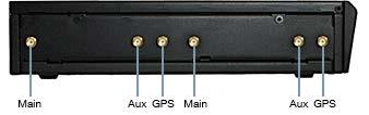
6 Antenna Image MSRP Type 12 Mag-mount Part # $44.99 Modem: SMA connector Mount, Connector, & Cabling Magnet mount Includes connectors Includes 12.5 ft cable 4 Mini Mag-mount Antenna with 12.5-foot Cable Part # Multi-band Omni-directional Antenna Part # $29.99 Modem: SMA connector Modem: SMA connector Magnet mount Includes connectors Includes 12.5 ft cable Pole/mast mount (pole not included) * - Requires separate connectors/cabling (see page 6) Indoor/Outdoor Panel Antenna Part # $ Modem: SMA connector Desktop/wall mount 3-in-1 Adhesive-Mount Antenna Part # $ GPS: SMA connector Adhesive mount Includes connectors 700 MHz 2700 MHz Wide Band Directional Antenna (Yagi/Log- Periodic) Part # $99.99 Modem: SMA connector* Pole/mast mount (pole not included) * - Requires separate connectors/cabling (see page 6) Antenna Main and Auxiliary Ports In most cases, a single antenna connected to the main antenna port will provide sufficient gain. To get full 4G speeds on LTE, or for enhanced performance on any modem, you may use two external antennas. Take extra care while attaching the cable to the modem. Be careful not to over-torque the SMA connector on the modem. Finger tight is sufficient (the maximum torque is 7kgf-cm). If you are using a single antenna, you may want to turn off the auxiliary antenna port. Log into the administration pages and go to Internet Connection Manager. Select the desired modem and click Edit. Select the Modem Settings tab. Deselect Enable Aux Antenna and click Submit. 4


7 AER3100 Models AER2100 Models AER1600 Models COR IBR1100/IBR1150 Models COR IBR900/IBR950 Models COR IBR600B/IBR650B Models (all) COR IBR600/IBR650 Models (all) ARC CBA850 5
 Directional Yagi (part # 170588-000) These antennas require a low-loss")
.")
. For orders of 500+ units, Cradlepoint may be able to source cable at competitive prices.")
8 COR IBR350 Models ARC Models CBA750B and MBR1400 Discontinued Models COR IBR600 Models PWD versions (WiFi side) ARC Models all other versions Additional Requirements & Recommendations The following antennas require additional adapters and/or cabling: Multi-band Omni-directional (part # ) Directional Yagi (part # ) These antennas require a low-loss coax cable with the N Male to SMA Male connectors OR an N Male to SMA Male adapter to attach to Cradlepoint equipment. Cradlepoint recommends using JEFA Tech LL400-Flex cable with N Male, SMA Male connectors (not sold by Cradlepoint). Cradlepoint has tested and certified 20- and 50-foot cables from JEFA Tech (jefatech.com/category/cradlepoint). Loss is approximately 6 db per 100 feet of cable (3 db per 50 feet, 1 db per 20 feet). For orders of 500+ units, Cradlepoint may be able to source cable at competitive prices. If you don t require a longer cable, you can purchase an N Male to SMA Male adapter. JEFA Tech offers this one: jefatech.com/category/cradlepoint. The pole/mast mount antennas come with approximately eight inches of cable. 6

9 Cradlepoint recommends using cable clamps or other cable-holding mechanisms to secure low-loss cable against a wall or pole. Use at least two clamps on the cable near the Cradlepoint router. This construction helps reduce stress on the cable/modem connector and increases product reliability. JEFA Tech provides this ½ cable clamp: jefatech.com/category/cradlepoint. Cradlepoint recommends adding lightning protection (ensure you have correct connections). See jefatech.com/category/cradlepoint. 7
10 Warranty Information 30-Day Money-Back Guarantee All Cradlepoint products are protected by Cradlepoint s 30-day money-back guarantee. If for any reason the performance of any product is not acceptable, simply return the product directly to the reseller with a dated proof of purchase. 90-Day Warranty Cradlepoint antennas are warranted for ninety (90) days against defects in workmanship and/or materials. Warranty cases may be resolved by returning the product directly to the reseller with a dated proof of purchase. Antennas may also be returned directly to Cradlepoint at the consumer s expense, with a dated proof of purchase and a Returned Material Authorization (RMA) number supplied by Cradlepoint. Cradlepoint shall, at its option, either repair or replace the product. Cradlepoint will pay for delivery of the repaired or replaced product back to the original consumer if located within the continental U.S. This warranty does not apply to any antennas determined by Cradlepoint to have been subjected to misuse, abuse, neglect, or mishandling that altered or damaged its physical or electronic properties. 8
 ST adapter Screw mount Features 2 x Cellular 2G/3G/4G Antennas (MIMO) o LTE/HSPA/GSM/GPRS/CDMA/UMTS o")
 bolt-mount antenna with 3M Cables")
11 3-in-1 GPS-GLONASS & Two Cellular (3G/4G/LTE) Screw-mount Antenna with 3M Cables Part # Cable, adapter, and mounts (pole not included) Includes 3m low loss CFD200 cable on cellular and RG-174 cable on GPS/Glonass, 3000mm ± 60mm long SMA(M) ST adapter Screw mount Features 2 x Cellular 2G/3G/4G Antennas (MIMO) o LTE/HSPA/GSM/GPRS/CDMA/UMTS o 698~960MHz/1710~2170MHz/2300~2700MHz/ MHz 1 x GPS/GLONASS /1602MHz Active Antenna IP67 Waterproof High Efficiency/Peak Gain Outdoor Antenna RoHS Compliant How It Works The 3-in-1 GPS-GLONASS and two cellular (3G/4G/LTE) bolt-mount antenna with 3M Cables is an omnidirectional heavy-duty, fully IP67 waterproof external M2M antenna for use in telematics, transportation and remote monitoring applications. It includes two LTE MIMO antennas and one GPS/GLONASS antenna, in the highest efficiency and peak gain possible. This antenna particularly finds its application in mobile video, vehicle communications, location and fleet management, safety & security, remote industrial equipment monitoring. The antenna consists of two LTE MIMO elements MHz, MHz, 2300~2700MHz, MHz. The antennas are designed to work equally well on LTE to deliver maximum dataspeed rates, or on legacy 2G and 3G frequencies where LTE is not available. The GNSS antenna is a wide-band GPS/ GLONASS element tuned to have optimum gain at MHz GPS and 1602MHz Glonass frequencies. 9


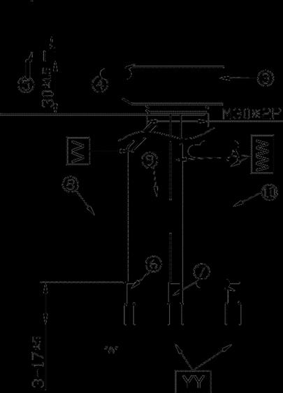
12 Mechanically, the unit has three high efficiency and gain antennas packed in an extremely robust IP67 direct mount antenna package with excellent isolation (20dB+). The strengthened domed housing is designed to deflect tree branches and wires that tend to catch and break shark fin or rigid whip antennas. The antenna has its own internal ground-plane and can radiate on any mounting environment such as metal or plastic without affecting performance. The internal components are individually screwed down onto a robust plate, preventing damage from regular vehicle vibrations. A completely waterproof mounting seal prevents water from leaking under the housing. Installing the 3-in-1 GPS-GLONASS & Two Cellular (3G/4G/LTE) Screw-mount Antenna with 3M Cables: 10


13 11
14 Designation Name Material Finish QTY 1 Housing PC 540 Black 1 2 Closed Cell Foam 3 M30 Nut Steel AISI Washer Steel AISI Waterproof Gasket 6 Heat Shrink Tube 7 Heat Shrink Tube 8 GPS-Glonass Label 9 2G/3G/4G MIMO1 10 2G/3G/4G MIMO2 11 3M Double Adhesive 12 M30x 2 Thread 32L CR 4305 Black 1 Silicone Rubber Ni Plated 1 Ni Plated 1 Black 1 PE (RG174) Black 1 PE (CFD200) Black 2 Coated Paper Orange 1 Coated Paper Gray 1 Coated Paper White 1 3M 9448 HK White Liner 1 Zinc Alloy Ni Plated 1 UU Cable Length 3000mm ± 60mm VV Cable Type RG174 Black 1 WW Cable Type CFD200 Black 2 XX YY Connector Type Connector Type SMA(M) ST Gold 1 SMA(M) ST Gold 2 12
15 Antenna Specifications LTE GSM 850 GSM 900 2G/3G/4G MIMO DCS PCS WCD A I ISM LTE Frequency 698~7 1710~1 1850~ ~ ~ ~ ~ ~ MHz MIMO 1 NOTE: The antennas attached to cables labeled MIMO1 have significantly better gain and less orientation dependence than their MIMO2 counterparts. Therefore, the MIMO1 cable should go to MAIN cellular. VSWR (max.) Efficiency % Peak Gain dbi MIMO 2 NOTE: The antennas attached to cables labeled MIMO1 have significantly better gain and less orientation dependence than their MIMO2 counterparts. Therefore, the MIMO1 cable should go to MAIN cellular. VSWR (max.) Efficiency % Peak Gain dbi Polarizatio n Impedanc e Vertic al 50Ω Ω GPS/GLONASS Centre Frequency MHz / 1602 MHz Bandwidth 10 MHz Radiation Efficiency 50% (without cable) Passive Zenith 4.0 dbi typ.(with ψ =140mm ground) VSWR 2 Impedance 50Ω DC Power Input Range 1.8V ~ 5V 13
16 DC input 1.8V 3.3V 4.0V 5.5V MHz VSWR LNA Gain Noise Figure Power Consumption Band Attenuation 1535MHz: -20dB 1520MHz: -20dB 1520MHz: -20dB 1520MHz: -20dB 1642MHz: -20dB 1642MHz: -20dB 1642MHz: -20dB 1642MHz: -20dB Cable 3m RG174 standard Connector SMA(M) standard Mechanical Antenna Dimensions Casing Waterproof 2G/3G/4G MIMO 1 2G/3G/4G MIMO 2 GPS/GLONASS Height 85.7mm x Diameter 145.6mm Wonderloy PC-540 PC/ABS Alloy IP67 3M Low Loss CFD-200 SMA(M) 3M Low Loss CFD-200 SMA(M) 3M RG-174 SMA(M) Environmental Operation Temperature -40 C to 85 C Storage Temperature -40 C to 90 C Humidity Non-condensing 65 C 95% RH NOTE: All measurements were conducted with 3m low loss CFD200 cable on cellular and RG-174 cable on GPS/Glonass. 14

17 5-in-1 GPS-GLONASS, Two Cellular (3G/4G/LTE) & Two WiFi 2.4/5 GHz Screw-mount Antenna with 3M Cables Part # Cable, adapter, and mounts Low-loss cable, allowing for lengths of up to 10 meters (32 and 9.70 ), critical for buses, trains, and other commercial transport applications 3m RG-174 standard, fully customizable SMA (M) standard, fully customizable adapter Screw mount Features 2 x Cellular (2G/3G/4G) Antennas (MIMO) 698~960MHz, 1710~2170MHz,2300~2700MHz, MHz) o 1 MIMO main antenna o 1 MIMO diversity antenna 1 x GPS/GLONASS /1602MHz Active Antenna 2 x 2.4GHZ/ 5GHz Antennas (MIMO) o 1 MIMO main antenna o 1*MIMO diversity antenna IP67 Waterproof Front End SAW Filter High Efficiency/Peak Gain Outdoor Antenna RoHS Compliant How It Works 15
18 The 5-in-1 GPS-GLONASS, two cellular (3G/4G/LTE) and two WiFi 2.4/5 GHz screw-mount antenna with 3M cables is an omni-directional heavy-duty, fully IP67 waterproof external M2M antenna for use in telematics, transportation and remote monitoring applications. This unique antenna delivers powerful MIMO antenna technology for cellular/lte and WiFi n and emerging ac, plus GPS/GLONASS for next generation multiple wireless technology systems, such as telematics. The GPS/GLONASS antenna has a Front End SAW Filter. Examples are new fleet management and real time video applications that demand high speed video uplink and downlink. High efficiency and high gain MIMO antennas are necessary to achieve the required signal to noise ratio and throughput required to solve these challenges. Five (5) high performance antennas are integrated into an extremely robust IP67 direct/permanent mount antenna package with excellent isolation (20dB+). The antenna has its own ground-plane and can radiate on any mounting environment like metal or plastic without affecting performance. The cables are low loss allowing for lengths of up to 10 meters (32 and 9.70 ), critical for buses, trains and other commercial transport applications. Installing the 5-in-1 GPS-GLONASS, Two Cellular (3G/4G/LTE) & Two WiFi 2.4/5 GHz WiFi Screw-mount Antenna with 3M Cables: 16
19 17
20 Designation Name Material Finish QTY 1 Housing PC 540 Black 1 2 Closed Cell Foam CR 4305 Black 1 18
21 Designation Name Material Finish QTY 3 M30 Nut Steel AISI 1215 Ni Plated 1 4 Washer Steel AISI 1215 Ni Plated 1 5 Waterproof Gasket Silicon Rubber Black 1 6 Heat Shrink Tube PE (RG174) Black 1 7 Heat Shrink Tube PE (CFD200) Black 4 8 Rubber Stopper Silicon Rubber Black 1 9 GPS-Glonass Label Coated Paper Orange /5 GHz MIMO1 Label 2.4/5 GHz MIMO2 Label 2G/3G/4G MIMO1 Label 2G/3G/4G MIMO2 Label Coated Paper Green 1 Coated Paper Light green 1 Coated Paper Gray 1 Coated Paper White 1 UU Cable Length 3000mm ± 30mm VV Cable Type RG174 Black 1 WW Cable Type CFD200 Black 4 XX Connector Type SMA(M) ST Gold 1 YY Connector Type RP-SMA(M) ST Gold 2 ZZ Connector Type SMA(M) ST Gold 2 19
22 Antenna Specifications 2G/3G/4G MIMO Frequency (MHz) VSWR Polarization 698~ ~ ~ Max Vertical 20
23 Impedance Frequency (GHz) VSWR Polarization Impedance 50Ω 2.4GHz/ 5GHz MIMO 2.4~ ~ Max Linear 50Ω Centre Frequency Bandwidth Radiation Efficiency Passive Zenith VSWR 2 Impedance DC Power Input Range MHz / 1602MHz 10MHz 50 (without cable) 4.0 typ (with ψ=140mm ground) 50Ω 3 ~ 5V GPS/GLONASS DC Input 3.5V 4.0V 5.5V MHz VSWR LNA Gain Noise Figure Power Consumption Band Attenuation Cable MHz: - 20dB 1642MHz: - 20dB 3m RG-174 standard, fully customizable 1520MHz: - 20dB 1642MHz: - 20dB 1520MHz: - 20dB 1642MHz: - 20dB 21
24 Connector SMA (M) standard, fully customizable 22

25 Low profile 5-in-1 MIMO LTE, MIMO WiFi (2.4/5Ghz), & GPS screw mount antenna with 5M cables Part # Features Rugged low profile design 2x Wideband LTE/cellular elements 2x 2.4 & 4.9-6GHz Wifi/WIMAX Elements Integrated GPS antenna How It Works The Panorama LGMM low profile MIMO antenna range has been designed to support the new generation of vehicular LTE routers. The antenna enclosure contains five isolated high performance antenna elements; two ultra-wideband elements covering MHz support MiMo/diversity at cellular/lte frequencies and two dual band elements covering & 4.9-6GHz support MIMO/diversity operation for WiFi and WiMAX. The LGMM also contains a high performance GPS antenna with an integrated 26dB gain LNA and high quality filtering to combat noise. The antenna does not require a metallic ground plane, and maintains a high level of performance even when mounted on a non-metallic surface. 23
26 Technical Drawing 24
27 Antenna Specifications Electrical Data Frequency Range (MHz) Elements 1 & / Elements 3 & / GHz Operational Bands Elements 1 & 2 LTE / Cellular Elements 3 & 4 WiFi / WiMAX Elements 1 & dbi Peak Gain: Isotropic Elements 1 & dbi Elements 3 & 4 2 dbi VSWR Elements 1 & 2 < 2.5:1 Elements 3 & 4 < 2:1 Isolation (in free space) Elements 1 & 2 > 15 db Elements 3 & 4 > 20 db Polarization Vertical Impedance 50Ω Max Input Power (W) 50 GPS Data Frequency Range (MHz) 1575 VSWR <2.0:1 ± 4 MHz Gain: LNA 26 db Polarization Right hand circular Operating Voltage 3 7 DC (fed via coax) Current Typical 14 ma Mechanical Data Dimensions Height 2.4 (62mm) Diameter 6.7 (176mm) Operating Temp -22 F / 176 F (-30 C / 80 C) Material ASA & diecast aluminum Color White Mounting Data Mounting type Panel mount Max panel thickness.236 (6mm) Mounting hole.75 (19mm) Cable Data Type RG174 GPS Cable Diameter.11 (2.8mm) Length 1 (0.3m) Termination FME (female) Type CS29 (double shielded RG58) Cell / LTE Cables x2 Diameter.2 (5mm) Length 1 (0.3m) Termination SMA (male) Type RG174 WiFi / WiMAX Cables x2 Diameter.11 (2.8mm) Length 1 (0.3m) Termination SMA (female) 25

28 GPS-GLONASS Screw-mount Antenna with 3M Cable Part # Cable, adapter, and mounts RG-174, 3000±30mm long (fully customizable) cable SMA Male (fully customizable) adapter Thread mount for pole or mast Features Height 28.5mm Diameter 47.8mm Heavy duty screw mount IP67 & IP69K Waterproof Rating GPS/GLONASS - 3M RG174 SMA(M) Customizable ROHS Compliant How It Works The GPS-GLONASS is a high-performance, boltmount GPS-GLONASS antenna designed for external use on vehicles and outdoor assets. Designed for heavy duty work with one piece C&C machined nickel plated steel base and threads, there are also convenient side slots for running cables laterally. Durable UV resistant PC housing is resistant to vandalism and direct attack. At only 29mm high it complies with the latest EU directives for height restrictions, while also enabling covert operation with a diameter of only 49mm. The antenna is completely waterproof with an IP67 rating, plus an additional IP69K rating for waterproof resistance against high-pressure water jets used in cleaning. An advanced front end SAW circuit noise filtering design is used to reduce potential interference common in such applications from other nearby high power radio transmitters. 26
29 Installing the GPS-GLONASS Screw-mount Antenna: 27

30 Package Contents 28
31 Antenna Specifications Frequency(MHz) Impedance(Ohm) GPS Patch Zenith GLONASS Patch Zenith VSWR Axial ratio Polarization ELECTRICAL GPS/GLONASS 1574~1606MHz 50Ω -1.4dB Passive Zenith -1.3dBi Zenith 2.0 max 3.0dB max RHCP Out Band Rejection fo = MHz fo ± 30 MHz 5dB Min. fo ± 50 MHz 20dB Min. fo ± 100 MHz 25dB Min. Input Voltage(V) Typ. 2.5~5.5V Total Zenith 27dB typical at 3.0V Current consumption(ma) 10mA typical at 3.0V Noise figure 1.3dB typical MECHANICAL Dimensions Φ49mm, Height 28.5mm Cable type Cable length Casing Connector Recommended Mounting Torque RG ±30mm UV Resistant PC SMA Male 24.5N m Maximum Mounting Torque 29.4N m ENVIRONMENTAL Temperature Range -40 C to 85 C Waterproof IP67 and IP69K Thermal Shock 100 cycles -40 C to +85 C Shock (drop test) Humidity 1m drop on concrete 6 axes Non-condensing 65 C 95% RH 29
, fully")
 IP67 Rated Custom cables and connectors available RoHS")
.")


32 GPS-GLONASS Mag-mount Antenna with 3M Cable Part # Cable, adapter, and mounts 3M RG ±50mm long, fully customizable cable SMA(M), fully customizable adapte Magnetic mount Features 1575MHz 1610MHz 40mm*38mm*10mm V 3m RG174 SMA(M) IP67 Rated Custom cables and connectors available RoHS Compliant How It Works The GPS-GLONASS Mag-mount Antenna with 3M Cable has a miniature, super low profile (only 10mm in height). It is designed for applications which require high positioning accuracy by combining signals from GPS and GLONASS systems. A high gain wide-band patch antenna on an integral ground delivers reliable performance. Fully IP67 waterproof rating allows use in outdoors environments. Front end SAW filter configuration eliminates potential LNA burn-out 30
33 from nearby out of band radiated power bursts from other antennas that may be co-located nearby. Installing the GPS-GLONASS Mag-mount Antenna with 3M Cable: Designation Name Material Finish QTY 1 AA.162 Antenna Housing Top ABS Black 1 2 AA.162 Antenna Housing Bottom ABS Black 1 3 AA.162 Sticker Gloss Silver PET Silver 1 4 Heat Shrink Tube PE Black 1 31
34 5 GPS-Glonass Label Coated Paper Orange 1 WW Connector Type SMA(M) ST Gold 1 XX Cable Length 3000±50mm 1 YY Cable Type RG174 Black 1 Antenna Specifications Electrical Centre Frequency Antenna Gain VSWR Impedanc e Outer Band Attenuation Pout at 1dB Gain Compression Point 1574~1610MHz 26 ± MHz 27 ± 1602MHz 2.0 max. 50Ω 1592±140MHz 15dB Min -6dBm Min. -2dBm Typ. 1.8V (min.) 3.0V (typ.) 5.5V (max.) DC input LNA Gain 22dB 28dB 31dB Noise Figure 2.6dB 2.6dB 2.9dB Power Consumption 5mA 10mA 23mA Mechanical Antenna Dimensions Housing Material Cable Connector 37.8 x 40.4 x 10mm UV Resistant ABS 3M RG174 (fully customizable) SMA(M) (fully customizable) Environmental Operation Temperature Storage -40 C to 85 C -40 C to 105 C 40% to 95% 32
35 Temperature Relative Humidity 33
36 12 Mag-mount Antenna with 12.5-foot Cable Part # dbi gain max For use with all AER, ARC, and COR products with integrated modems. NOTE: LTE band 7 (2600 MHz) is not covered, which affects some international versions (LP2 and LP3 models). Cable, adapter, and mounts (pole not included) 12.5 cable SMA Male adapter Optional magnetic wall mount; cable clamps must be vertical Features Connects directly to Cradlepoint modem with included cable and connector Multi-band versatility Easy to install 12" Magnet Mount Antenna Removable transfer from one vehicle to another Omni-directional Weatherproof Made of stainless steel Requires metal mount plane (minimum 3.5 in. diameter) 12.5 feet of cable How It Works Cradlepoint s dual-band, omni-directional Magnet-Mount Antenna will collect the cell tower signal and send it through the cable to the integrated or embedded Cradlepoint modem and router. When the modem transmits, the signal is transferred directly to the antenna and broadcast back to the cell tower. Installing the Magnet-Mount Antenna Attach the Magnet-Mount Antenna to any metal area on top of the roof of the vehicle. The best location is one clear of obstacles and as high on the vehicle as possible. Although small, the rare earth magnet is quite strong and won t fall off at high speeds. Make sure the area under the magnet is clean so as not to damage the vehicle s paint and to ensure a strong connection. Bring the cable into the vehicle through a door frame the cable is protected by the door s rubber molding. Do not run the cable through a window because when the window is rolled up and the door is opened the antenna cable will be pulled this is likely to destroy your antenna and/or scratch your paint. Connect the magnet-mount antenna cable to the Cradlepoint router antenna port. 34
37 Antenna Specifications Part Number: Frequency Range: MHz, MHz, MHz, MHz, MHz, MHz Impedance: 50 ohms Antenna Gain: MHz, 1.9 dbi / MHz, 5.12 dbi / MHz, 3.1 dbi / MHz, 4.0 dbi / MHz, 6.12 dbi / MHz, 2.3 dbi Radiation: Omni-directional Polarization: Vertical Ground Plane: Metal Ground Plane required (minimum 3.5 inch diameter) Connector: SMA Male Material: Whip Stainless Steel Coaxial Cable: RG feet / 3.8 meters Height: inches / 31 cm Mount: Rare earth magnet 35
38 4 Mini Mag-mount Antenna with 12.5-foot Cable Part # dbi gain max For use with all AER, ARC, and COR products with integrated modems. NOTE: LTE band 7 (2600 MHz) not covered, which affects some international versions (LP2 and LP3 models). Cable, adapter, and mounts (pole not included) 12.5 cable: SMA Male adapter Cable clamps must be vertical. Features Connect directly to Cradlepoint with included cable and connector Multi-band versatility Easy to install 4" Magnet Mount Antenna Removable: transfer from one vehicle to another Omni-directional Weatherproof Requires Metal Mount Plane (minimum 3.5 diameter) 12.5 feet of cable How It Works Cradlepoint s Dual-Band Omni-Directional Antenna will collect the cell tower signal and send it through the cable to the integrated or embedded Cradlepoint modem and router. When the modem transmits, the signal is transferred directly to the antenna and broadcast back to the cell tower. Installing the Magnet-Mount Antenna Attach the Magnet-Mount Antenna to any metal area on top of the roof of the vehicle. The best location is one clear of obstacles and as high on the vehicle as possible. Although small, the rare earth magnet is quite strong and won t fall off at high speeds. Make sure the area under the magnet is clean so as not to damage the vehicle s paint and to ensure a strong connection. Bring the cable into the vehicle through a door frame; the cable is protected by the door s rubber molding. Do not run the cable through a window because when the window is rolled up and the door is opened, it will pull the antenna cable. This is likely to destroy your antenna and/or scratch your paint. Connect the magnet-mount antenna cable to the Cradlepoint router antenna port. 36
39 Antenna Specifications Part Number: Frequency Range: MHz, MHz, MHz, MHz, MHz, MHz Impedance: 50 ohms Antenna Gain: MHz, 1.7 dbi / MHz, 2.12 dbi / MHz, 1.5 dbi / MHz, 3.12 dbi / MHz, 3.12 dbi / MHz, 1.4 dbi Radiation: Omni-directional Polarization: Vertical Ground Plane: Metal Ground Plane required (minimum 3.5 inch diameter) Connector: SMA Male Material: Whip Plastic-coated steel wire Coaxial Cable: RG feet / 3.8 meters Height: 4.2 inches / 10.6 cm Mount: Rare earth magnet 37


40 Multi-band Omni-directional Antenna Part # ohm For use with all AER, ARC, and COR products with integrated modems. Features High-gain Weather resistant Built-in ground plane Slim and unobtrusive Mounting bracket included Installs easily For fixed installations How It Works Cradlepoint s Multi-band Omni-directional Antenna will collect the cell tower signal and send it through the cable to the integrated or embedded Cradlepoint modem and router. When the modem transmits, the signal is transferred directly to the antenna and broadcast back to the cell tower. Thank You for Purchasing a Cradlepoint Antenna Please read all instructions before installing your antenna and check the parts supplied against those listed in this guide. Cradlepoint s weatherproof, fiberglass-encased antenna is omni-directional and ideal for many exterior building locations, such as homes, offices, stores, and warehouses. The innovative design results in high efficiency and low signal loss, which means more signal supplied to your router s modem. This multi-band, high-performance, omni-directional antenna supports multiple frequencies (specifications below). Package Contents Multi-Band Omni-Directional Antenna Wall Mount Bracket U-Bolt Assembly N Type Female Connector Determine Your Mounting Location The antenna should be mounted high on the building with no obstructions. There is a compromise between installing the antenna as high as possible and keeping the cable run short to reduce signal loss. (The longer the cable, the greater the signal loss will be.) For cable runs of less than 20 feet (recommended), Cradlepoint recommends JEFA Tech LL400 cable with N Male, SMA Male connectors (not sold by Cradlepoint). Cradlepoint has tested 20- and 50-foot cables from JEFA Tech and suggests using this configuration. Using less expensive (often higher loss) cables or using extra adapters with other cables may result in significantly reduced performance. 38
41 Make sure your mounting location is as far away as possible from other antennas and upright objects such as flagpoles. Be careful not to kink or crush the antenna cable or bend it tightly during installation. This can lead to poor performance and signal loss. It is important to mount the antenna vertically; mounting horizontally or at an angle will significantly degrade performance. When two antennas are used, there must be at least 1 (12 inches) separation between the edges of the two antennas. This spacing will provide enough spatial diversity in an outdoor environment for MIMO/diversity operation. Technical Support Visit knowledgebase.cradlepoint.com Disclaimer: The information provided by Cradlepoint is believed to be complete and accurate. However, no responsibility is assumed by Cradlepoint, Inc. for any business or personal losses arising from its use, or for any infringements of patents or other rights of third parties that may result from its use. Antenna Specifications Part Number: Frequency Range: MHz / MHz / MHz Impedance: 50 ohms Antenna Gain: 3.5 dbi MHz / 4.5 dbi MHz / 3.1 dbi Radiation: Omni Polarization: Vertical Ground Plane: Built-in Connector: N Type Female Internal Material: Copper Height: 12.6 inches / 32 cm 39
42 Indoor/Outdoor Panel Antenna Part # For use with all AER, ARC, and COR products with integrated modems Features Best solution for 4G 2x2 Worldwide LTE MIMO applications Covers fallback 2G/3G frequencies too (HSPA/UMTS/WCDMA/GSM/GPRS) MHz, MHz, MHz High Efficiency Indoor and Outdoor Antenna Waterproof IP67 Wall Mount or Desktop Mount Dimension: 164mm*164mm*36.5mm 2* Low Loss 1M CFD-200 Cables - SMA(M) Disclaimer: The information provided by Cradlepoint is believed to be complete and accurate. However, no responsibility is assumed by Cradlepoint, Inc. for any business or personal losses arising from its use, or for any infringements of patents or other rights of third parties that may result from its use. How It Works The Gemini LTE 4G MIMO 2X2 is a robust external antenna that is fully IP67 waterproof for use with all 2G/3G/4G MIMO cellular routers and Access points worldwide. It includes two embedded high efficiency LTE MIMO antennas. The antenna elements operate at all common and 4G LTE bands worldwide: MHz, MHz, MHz, which also include the 2G and 3G bands, meaning the antenna can also be used as fallback on 2G or 3G applications. High isolation and low ECC between the two embedded MIMO antennas prevents self-interference. Low loss cables are used to keep efficiency high over long cable lengths up to 5 meters. This unique antenna offers two methods for easy installation, both indoors and outdoors. A bracket on the back of the antenna enables easy wall installation, keeping your work area clean and spacious. The antenna can also be placed on a flat surface using the stand holder for easy and quick installation. Typical Applications HD Real-time Streaming Video over LTE Intelligent Transport Systems Internet of Things (IoT market) Digital Signage HD Broadcast Systems Wireless 4G LTE MIMO M2M devices with legacy 3G Functionality Cable length and connector types are customizable. Package Contents 40
43 Line Drawing 41
44 Desktop Stand Installation 42
45 Wall Mount Installation 43
46 Antenna Specifications Part Number: Frequency Range: MHz / MHz / MHz / MHz / MHz / MHz / MHz Nominal Impedance: 50 ohms Antenna Gain: 4.76 dbi MHz / 3.42 dbi MHz / 3.07 dbi MHz / 5.04 dbi MHz / 5.12 dbi MHz / 5.08 dbi MHz / 2.41 dbi MHz Horizontal Beamwidth: 70 degrees Vertical Beamwidth: 50 degrees Polarization: Vertical Maximum Power: 100 watts Connector: SMA Male Standard Dimension: 164 x 164 x 36.5 mm Weight: 400 g Radome Material: UV Protection ABS 44
 2x LTE: 2 meter Low loss NFC-200 SMA(M)ST Dimensions: 205.8mm x 58mm x 12.")
47 3-in-1 Adhesive-Mount Antenna Part # For use with all AER, ARC, and COR products with integrated modems. Features IP67 Antenna 1x GPS-GLONASS: 2 meter RG-174 SMA(M) 2x LTE: 2 meter Low loss NFC-200 SMA(M)ST Dimensions: 205.8mm x 58mm x 12.4mm RoHS Compliant Disclaimer The information provided by Cradlepoint is believed to be complete and accurate. However, no responsibility is assumed by Cradlepoint, Inc. for any business or personal losses arising from its use, or for any infringements of patents or other rights of third parties that may result from its use. How It Works Cradlepoint s 3-in-1 adhesive mount antenna will collect the cell tower signal and send it through the cable to the integrated or embedded Cradlepoint modem and router. When the modem transmits, the signal is transferred directly to the antenna and broadcasted back to the cell tower. Thank You for Purchasing a Cradlepoint Antenna Please read all instructions before installing your antenna, and check the parts supplied against those listed in this guide. Cradlepoint s weather resistant, encased antenna is wide band log periodic directional and ideal for many exterior building locations, such as homes, offices, stores and warehouses. 45


48 Line Drawing 46
49 Antenna Specifications Part Number: Frequency Range: MHz / MHz / MHz / MHz / MHz / MHz / MHz / MHz Nominal Impedance: 50 ohms Antenna Gain (4G/3G MIMO1): 3.61 dbi MHz / 2.38 dbi MHz / 0.02 dbi MHz / 3.31 dbi MHz / 3.41 dbi MHz / 1.21 dbi MHz / 4.22 dbi MHz / 1.80 dbi MHz Antenna Gain (4G/3G MIMO2): 3.44 dbi MHz / 2.17 dbi MHz / 1.59 dbi MHz / 3.37 dbi MHz / 3.41 dbi MHz / 3.21 dbi MHz / 5.87 dbi MHz / 4.81 dbi MHz Connector: SMA Male Dimension: 205.8mm x 58mm x 12.4mm Weight: 250g Temperature Range: 40 to 185 F ( 40 to 85 C) 47

50 700 MHz 2700 MHz Wide Band Directional Antenna (Yagi/Log-Periodic) Part # For use with all AER, ARC, and COR products with integrated modems. Cable, adapter, and mounts sold separately N Male/SMA Male adapter Includes mount for pole or mast Cable clamps sold separately Features High-gain Directional Pipe mounting hardware included Installs easily Weather resistant Wide bandwidth 50 Ohms VSWR: 1.5 Max About 8 of cable Disclaimer: The information provided by Cradlepoint is believed to be complete and accurate. However, no responsibility is assumed by Cradlepoint, Inc. for any business or personal losses arising from its use, or for any infringements of patents or other rights of third parties that may result from its use. How It Works Cradlepoint s Wide Band Directional Antenna (Log-Periodic) will collect the cell tower signal and send it through the cable to the integrated or embedded Cradlepoint modem and router. When the modem transmits, the signal is transferred directly to the antenna and broadcasted back to the cell tower. Thank You for Purchasing a Cradlepoint Antenna Please read all instructions before installing your antenna, and check the parts supplied against those listed in this guide. Cradlepoint s weather resistant, encased antenna is wide band log periodic directional and ideal for many exterior building locations, such as homes, offices, stores and warehouses. 48
.")
51 The innovative design results in high efficiency and low signal loss, which means more signal to your router s modem. This multi-band, high-performance, directional antenna supports multiple frequencies (Specifications below). Package Contents (A)Wide Band Log Periodic Directional Antenna & L Bracket (B)2 U-Bolts (C)2 Pipe Brackets (D)4 1/4 Washers (E)4 1/4 Split-Lock Washers (F)4 1/4-20 nuts Antenna Mounting Instructions 1 Install U-Bolt (B) on pole. 2 Slide Pipe Clamp (C) over U-Bolt (B) Flat side away from pipe. 3 Slide antenna bracket (A) onto U-Bolt (B) in desired location. NOTE: Antenna may be installed on a variety of pipe angles; ensure antenna is pointing at cell tower and is vertical with the drip hole at the bottom. 4 Install Flat washer (D), split lock washer (E) and nut (F), tighten as appropriate. 49
52 NOTE: A second U-Bolt assembly has been included to strengthen antenna mounting in windy areas. Repeat steps 1 through 4 to install. Antenna Installation The antenna should be mounted as shown in the illustration above. The included mounting bracket is adjustable and will accommodate pipe diameters from 1.25 to 2 (pipe not included). Mount the antenna so that there is at least 3 feet of clearance in all directions around it. Position the antenna so that it has the most unobstructed line of sight to the cellular service provider s strongest signal. There is a compromise between installing the antenna as high as possible and keeping the cable run short to reduce signal loss. (The longer your cable, the greater the signal loss will be.) For cable runs of less than 20 feet (recommended), Cradlepoint recommends JEFA Tech LL400 cable with N Male, SMA Male connectors (not sold by Cradlepoint). Cradlepoint has tested 20 and 50 foot cables from JEFA Tech and suggests using this configuration. FINGER TIGHT ONLY. Using less expensive (often higher loss) cables or using extra adapters with other cables may result in significantly reduced performance. When two antennas are used, there must be at least 1 (12 inches) separation between the edges of the two antennas. This spacing will provide enough spatial diversity in outdoor environments for MIMO/diversity operation. Both antennas should focus the main beam in the same direction of strong cellular signal. 50

53 WARNING: Lightning protection is recommended for all installations (not sold by Cradlepoint). JEFA Tech offers one: jefatech.com/category/cradlepoint. Wilson Electronics offers one compatible with this device: Wilson Part# Take extreme care to ensure that neither you nor the antenna come near any electric power lines. Adjusting the Antenna for Maximum Performance To adjust the antenna for best performance, connect it to your router, log into the router ( and access the modem signal strength page. Turn the Antenna in 10- degree increments while checking the signal level (dbi). At each point you may need to wait a few seconds as the display updates. Signal readings appear as a negative number (for example, 86). The larger the number, the more powerful the signal ( 75 is stronger than 84). Once you have obtained the strongest signal, fully tighten the mounting hardware. Disconnect the cable, route the extension cable to the router location, and reconnect. Weatherproof all connections. 700 MHz 2700 MHz Wide Band Directional Antenna (Yagi/Log-Periodic) Antenna Specifications Part Number: Frequency Range: MHz / MHz / MHz / MHz / MHz / MHz Nominal Impedance: 50 ohms 51
54 Antenna Gain: 8.0 dbi MHz / 8.0 dbi MHz / 7.0 dbi MHz / 9.0 dbi MHz / 10.5 dbi MHz / 10.0 dbi MHz Horizontal Beamwidth: 70 to 90 degrees Vertical Beamwidth: 85 to 110 degrees F/B ratio: >20 db Polarization: Vertical Maximum Power: 100 watts Connector: N-Female (requires cable to connect to Cradlepoint router) Dimension: 11.4 x 8.3 x 2.6 Weight: 3.3 lbs Temperature Range: 40 to 158 F ( 40 to 70 C) Rated Wind Velocity: 134 MPH Lightning protection: DC grounded 52
Cradlepoint Antenna Ordering and Installation Guide January 29, 2018
 Cradlepoint Antenna Ordering and Installation Guide January 29, 2018 Preface Right of Revision Cradlepoint reserves the right to revise this publication and to make changes in the content thereof without
Cradlepoint Antenna Ordering and Installation Guide April 22, 2015
 Cradlepoint Antenna Ordering and Installation Guide April 22, 2015 Preface Right of Revision Cradlepoint reserves the right to revise this publication and to make changes in the content thereof without
Pantheon Antenna 3in1 MA.710 Screw-Mount (Permanent Mount) 2 x 2G/3G/4G LTE MIMO Cellular Antenna 1 x GPS/GLONASS Antenna
 2 x 2G/3G/4G LTE MIMO Cellular Antenna 1 x GPS/GLONASS Antenna") Pantheon MA710.A.ABI.001 Specification Part No. Product Name Feature MA710.A.ABI.001 Pantheon Pantheon Antenna 3in1 MA.710 Screw-Mount (Permanent Mount) 2 x 2G/3G/4G LTE MIMO Cellular Antenna 1 x GPS/GLONASS
Pantheon MA710.A.ABI.001 Specification Part No. Product Name Feature MA710.A.ABI.001 Pantheon Pantheon Antenna 3in1 MA.710 Screw-Mount (Permanent Mount) 2 x 2G/3G/4G LTE MIMO Cellular Antenna 1 x GPS/GLONASS
Specification. Hercules MA520.A.BC.008
 MA520.A.BC.008 on ground-plane Hercules MA520.A.BC.008 Specification Part No. Product Name MA520.A.BC.008 Hercules 2in1 Cellular and Wi-Fi Heavy Duty Screw Mount Antenna - Cellular 2G/3G HSPA/GSM/GPRS/CDMA/EVDO/UMTS/WCDMA
MA600.A B C MA600 Spartan Screw-mount 3in1 Combination Antenna GPS Cellular GSM/CDMA/HSPA/UMTS 2.4GHz / 5GHz
 MA.6 on ground-plane MA.6 Specification Part No. MA6.A31111.B3111.C3111 Product Name MA6 Spartan Screw-mount 3in1 Combination Antenna GPS Cellular GSM/CDMA/HSPA/UMTS 2.4GHz / GHz Feature High performance
Specification. Spartan MA650.A.AB.002
 MA650.A.AB.002 on ground-plane Spartan MA650.A.AB.002 Specification Part No. Product Name Feature MA650.A.AB.002 Spartan 2in1 MA.650 with 10M cable length Low Profile Screw Mount (Permanent Mount) GPS/GLONASS
Specification. Spartan MA605.A.ABC in1 MA.605 Low Profile Screw-Mount (Permanent Mount) GPS/GLONASS/Cellular/2.4GHz ~ 5GHz Combination Antenna
 GPS/GLONASS/Cellular/2.4GHz ~ 5GHz Combination Antenna") MA65.A.ABC.1 on ground-plane Spartan MA65.A.ABC.1 Specification Part No. Product Name Feature MA65.A.ABC.1 Spartan 3in1 MA.65 Low Profile Screw-Mount (Permanent Mount) GPS/GLONASS/Cellular/2.4GHz ~ 5GHz
MA65.A.ABC.1 on ground-plane Spartan MA65.A.ABC.1 Specification Part No. Product Name Feature MA65.A.ABC.1 Spartan 3in1 MA.65 Low Profile Screw-Mount (Permanent Mount) GPS/GLONASS/Cellular/2.4GHz ~ 5GHz
SPECIFICATION. Product Name : MA104 GPS/Cellular Combination Hercules Screw-mount [Permanent mount]
![SPECIFICATION. Product Name : MA104 GPS/Cellular Combination Hercules Screw-mount [Permanent mount]](/thumbs/81/83682830.jpg "SPECIFICATION. Product Name : MA104 GPS/Cellular Combination Hercules Screw-mount [Permanent mount]") SPECIFICATION Part No. : MA104.C.AB.015 Product Name : MA104 GPS/Cellular Combination Hercules Screw-mount [Permanent mount] Feature : Low profile - Height 29 mm and Diameter 49mm Heavy duty screw mount
SPECIFICATION Part No. : MA104.C.AB.015 Product Name : MA104 GPS/Cellular Combination Hercules Screw-mount [Permanent mount] Feature : Low profile - Height 29 mm and Diameter 49mm Heavy duty screw mount
SPECIFICATION. MIMO Dual Band 2.4/5.0GHz. ISM Bands/ZigBee/WLAN/Bluetooth. IEEE n/IEEE ac. High Isolation between Antenna Elements
 SPECIFICATION Part No. : MA510.C.CG.005 Product Name : Heavy Duty Screw Mount Antenna MIMO Dual Band 2.4/5.0GHz Features : 2.4GHz/5.0GHz suitable for ISM Bands/ZigBee/WLAN/Bluetooth IEEE.802.11n/IEEE.802.11ac
SPECIFICATION. Product Name : Heavy Duty Screw Mount Antenna MIMO Dual Band 2.4/5.0GHz
 SPECIFICATION Part No. : MA510.C.CG.005 Product Name : Heavy Duty Screw Mount Antenna MIMO Dual Band 2.4/5.0GHz Features : 2.4GHz/5.0GHz suitable for ISM Bands/ZigBee/WLAN/Bluetooth IEEE.802.11n/IEEE.802.11ac
SPECIFICATION. MIMO Single Band 2.4GHz. ISM Bands/ZigBee/WLAN/Bluetooth. High Isolation between Antenna Elements. UV and vandal resistant PE housing
 SPECIFICATION Part No. : MA515.C.CG.001 Product Name : Heavy Duty Screw Mount Antenna MIMO Single Band 2.4GHz Features : 2.4GHz suitable for ISM Bands/ZigBee/WLAN/Bluetooth IEEE.802.11n High Isolation
SPECIFICATION. Part No. : A.03.B Product Name : 40dB GPS Hercules Heavy Duty Screw Mount Antenna For long cable lengths above 5M
 SPECIFICATION Part No. : A.03.B.1001111 Product Name : 40dB GPS Hercules Heavy Duty Screw Mount Antenna For long cable lengths above 5M Description : Three Stage 40dB Height 29mm Diameter 52mm Applications
SPECIFICATION : MA700.A.ABC.001
 SPECIFICATION Part No. : MA7.A.ABC.1 Product Name : Pantheon Antenna 3in1 MA.7 Screw-Mount (Permanent Mount) GPS/GLONASS/GALILEO / LTE Cellular / 2.4GHz / GHz Combination Antenna Features : Highest Efficiency/Peak
SPECIFICATION. G21 GSM Hercules Gen.II Penta Band Cellular Antenna
 SPECIFICATION G21 GSM Hercules Gen.II Penta Band Cellular Antenna Part No. : G21.B.301111 Product Name : G21 GSM Hercules Gen.II Penta Band Cellular Antenna Screw-mount (Permanent mount) GSM/GPRS/CDMA/EVDO/UMTS/HSPA/WCDMA
SPECIFICATION. SPE /D/AS Page 1 of 24 MA.520.C.B C Part No. : MA520.A.BC.008
 SPECIFICATION Part No. : MA520.A.BC.008 Product Name : Hercules 2in 1 Cellular and Wi-Fi Heavy Duty Screw Mount Antenna - Cellular 2G/3G HSPA/GSM/GPRS/CDMA/EVDO/UMTS/WCDMA 850/900/1800/1900/2100 MHz -
SPECIFICATION. G21.W White Hercules Gen II Penta Band Cellular Antenna
 SPECIFICATION G21.W White Hercules Gen II Penta Band Cellular Antenna Part No. : G21.B.W.301111 Product Name : G21.W Hercules Gen.II Penta Band Cellular Antenna Screw-mount (Permanent mount)- White Version
SPECIFICATION. Product Name : MA130 GPS/GLONASS/GALILEO and ISM Band 868MHz 2 in 1 Combination Hercules Screw Mount (Permanent Thread Mount)
") SPECIFICATION Part No. : MA130.A.LP.002 Product Name : MA130 GPS/GLONASS/GALILEO and ISM Band 868MHz 2 in 1 Combination Hercules Screw Mount (Permanent Thread Mount) Features : Stable and High efficiency
SPECIFICATION Part No. : MA130.A.LP.002 Product Name : MA130 GPS/GLONASS/GALILEO and ISM Band 868MHz 2 in 1 Combination Hercules Screw Mount (Permanent Thread Mount) Features : Stable and High efficiency
SPECIFICATION. G21 GSM Hercules Gen.II Penta Band Cellular Antenna
 SPECIFICATION G21 GSM Hercules Gen.II Penta Band Cellular Antenna Part No. : G21.B.301111 Product Name : G21 GSM Hercules Gen.II Penta Band Cellular Antenna Screw-mount (Permanent mount) GSM/GPRS/CDMA/EVDO/UMTS/HSPA/WCDMA
SPECIFICATION. G21 GSM Hercules Gen.II Penta Band Cellular Antenna. Screw-mount (Permanent mount)
") SPECIFICATION G21 GSM Hercules Gen.II Penta Band Cellular Antenna Part No. : G21.B.301111 Product Name : Hercules Gen.II Penta Band Cellular Antenna Screw-mount (Permanent mount) Features : GSM/GPRS/CDMA/EVDO/UMTS/HSPA/WCDMA
SPECIFICATION G21 GSM Hercules Gen.II Penta Band Cellular Antenna Part No. : G21.B.301111 Product Name : Hercules Gen.II Penta Band Cellular Antenna Screw-mount (Permanent mount) Features : GSM/GPRS/CDMA/EVDO/UMTS/HSPA/WCDMA
SPECIFICATION. 3in1 Combination Antenna. GPS/GLONASS/GALILEO 1575~1602MHz. Cellular GSM/CDMA/HSPA/UMTS. Dual band Wi-Fi 2.4GHz / 5.
 SPECIFICATION Part No. : MA600.A.ABC.007 Product Name : MA600 Spartan Screw mount 3in1 Combination Antenna GPS/GLONASS/GALILEO 1575~1602MHz Cellular GSM/CDMA/HSPA/UMTS Dual band Wi-Fi 2.4GHz / 5.8GHz Feature
SPECIFICATION. Heavy Duty Screw Mount Antenna. Features : Wi-Fi/ISM Bands/ZigBee/WLAN/ Bluetooth. UV and Vandal Resistant ABS Housing
 SPECIFICATION Part No. : WS.02.B.205111 Product Name : 4dBi 2.4GHz Omni-Directional Heavy Duty Screw Mount Antenna Features : Wi-Fi/ISM Bands/ZigBee/WLAN/ Bluetooth UV and Vandal Resistant ABS Housing
Antenna. Wilson. Wide-Band Panel Antenna Window, Ceiling, Wall & Outdoor Mounts. Appearance of device and accessories may vary.
 Antenna Window, Ceiling, Wall & Outdoor Mounts WINDOW PART# 304452-50 Ohms PART# 304472-75 Ohms CEILING PART# 304451-50 Ohms PART# 304471-75 Ohms WALL PART# 301135-50 Ohms UPGRADE-PART# 301147-50 Ohms
Heavy Duty Screw Mount Antenna - Dual-Band GHz
 Hercules WS.01.B.305151 Description: Heavy Duty Screw Mount Antenna - Dual-Band 2.4 5.2GHz Features: 2.4GHz 5.2GHz suitable for ISM Bands/ZigBee/WLAN/Bluetooth IEEE.802.11/IEEE.802.15 UV and Vandal Resistant
Specification. Optimus MA220.LB.001. MA220 2in1 - GPS-GLONASS - LTE External Adhesive Antenna for Glass and Plastic Mount. Feature
 Optimus MA220.LB.001 Specification Part No. MA220.LB.001 Product Name Optimus MA220 2in1 - GPS-GLONASS - LTE External Adhesive Antenna for Glass and Plastic Mount Feature GPS-GLONASS - High gain LNA up
SPECIFICATION. Olympian Direct Mount Ultra Wide-Band 2G/3G/4G LTE/Cellular/CDMA and Wi-Fi Antenna. 698 to 960MHz, 2.4GHz and 1710 to 2700MHz
 SPECIFICATION Part Number: G30.B.108111 Product Name: Olympian Direct Mount Ultra Wide-Band 2G/3G/4G LTE/Cellular/CDMA and Wi-Fi Antenna For 2G/3G/4G Applications LTE/GSM/CDMA/DCS/PCS/WCDMA/UMTS/HSDPA/GPRS/EDGE/IMT
Ultra-Low Profile Miniature Magnet Mounted GPS-GLONASS Antenna
 Topside View Underside View Ulysses AA.16.301111 Specification Part No. AA.16.301111 Product Name Ulysses Ultra-Low Profile Miniature Magnet Mounted GPS-GLONASS Antenna Feature 1575MHz 1610MHz 40mm*38mm*10mm
SPECIFICATION. Product Name : Optimus MA220 2in1 GPS-GLONASS-GALILEO/ LTE External Adhesive Antenna for Glass and Plastic Mount
 SPECIFICATION Part No. : MA220.LB.001 Product Name : Optimus MA220 2in1 GPS-GLONASS-GALILEO/ LTE External Adhesive Antenna for Glass and Plastic Mount Features : GPS-GLONASS-GALILEO - High gain LNA up
SPECIFICATION. 3in1 Combination Antenna GPS/GLONASS/GALILEO 1575~1602MHz Cellular GSM/CDMA/HSPA/UMTS 2.4GHz / 5GHz
 SPECIFICATION Part No. : MA6.A.ABC.6 Product Name : MA6 Spartan Screw-mount 3in1 Combination Antenna GPS/GLONASS/GALILEO 17~162MHz Cellular GSM/CDMA/HSPA/UMTS 2.4GHz / GHz Feature : High performance outdoor
SPECIFICATION. Part No. : MA850.A.LBICG.002. Product Name : MA850 5in1 Permanent Mount Antenna LTE MIMO*2, Wi-Fi MIMO*2 & GPS/GLONASS/BeiDou
 SPECIFICATION Part No. : MA850.A.LBICG.002 Product Name : MA850 5in1 Permanent Mount Antenna LTE MIMO*2, Wi-Fi MIMO*2 & GPS/GLONASS/BeiDou Features : 2* LTE MIMO 698~960MHz/1710~2170MHz/2490~2690MHz 2*
Specification. Part No. : A.90.A
 Specification Part No. : A.90.A.101111 Product Name : Bolt High Gain Low Profile GNSS L1 GPS/GLONASS Permanent Mount Antenna with High Out of Band Rejection Features : 30dB GPS Gain, 25dB GLONASS Gain
SPECIFICATION. Part No. : MA1060.A.LBCT.001
 SPECIFICATION Part No. : MA1060.A.LBCT.001 Product Name : Raptor I MA1060 Sharkfin 4in1 Next Generation Permanent Mount External Antenna with LTE, GNSS, Wi-Fi and AM/FM Features : High Efficiency Omnidirectional
SPECIFICATION. Part No. : MA673.A.CGH.004. Product Name : Spartan Antenna 3in1 MA673. Features : ac compatible
 SPECIFICATION Part No. : MA673.A.CGH.004 Product Name : Spartan Antenna 3in1 MA673 Low Profile Screw-Mount (Permanent Mount) 3 * 2.4/5.8GHz MIMO 802.11ac antenna Features : 802.11ac compatible IP67 Waterproof
SPECIFICATION. Part No. : MA303.A.LB.002. Product Name : MA303 SAUCER Magnetic Mount GPS/GLONASS and Cellular 2G/3G 2in1 Combination Antenna
 SPECIFICATION Part No. : MA303.A.LB.002 Product Name : MA303 SAUCER Magnetic Mount GPS/GLONASS and Cellular 2G/3G 2in1 Combination Antenna Features : IP65 Water Resistant - GPS/GLONASS - High gain LNA
Guide. Installation. Wilson Electronics, Inc. Direct Connection High Power iden Amplifi er 800 MHz Band. Contents:
 Amplifier Installation Guide Direct Connection High Power iden Amplifi er 800 MHz Band Contents: Guarantee and Warranty 1 Before Getting Started / How it Works 3 Installing a Wilson Outside Antenna - In-Vehicle
Antenna and Cable Options Summary
 Antenna and Cable Options Summary Virtual Access offers a variety of antennas as every 3G/4G wireless deployment is different. When selecting an antenna for your device, you should consider factors such
Specification. Stream MA208.A.AB.007. GPS and LTE/GSM/UMTS (2G/3G/4G 700Mhz to 960MHz/1710MHz to 2200MHz) Combination Antenna.
 Combination Antenna.") Topside View Underside View Stream MA208.A.AB.007 Specification Part No. MA208.A.AB.007 Product Name Stream GPS and LTE/GSM/UMTS (2G/3G/4G 700Mhz to 960MHz/1710MHz to 2200MHz) Combination Antenna Feature
Topside View Underside View Stream MA208.A.AB.007 Specification Part No. MA208.A.AB.007 Product Name Stream GPS and LTE/GSM/UMTS (2G/3G/4G 700Mhz to 960MHz/1710MHz to 2200MHz) Combination Antenna Feature
SPECIFICATION. Part No. : MA230.LBC.002
 SPECIFICATION Part No. : MA230.LBC.002 Product Name : MA.230 STREAM 3 in 1 High Performance Adhesive Mount Combination Antenna GNSS - GPS/Glonass Cellular - LTE/HSPA/GSM/CDMA/UMTS Wi-Fi - 2.4/5 GHz Description
MaxWave 4x4 MIMO Train Antenna
 Electrical Features High Efficiency Superior Isolation Patented Pattern Diversity System Features 4x4 Cellular MIMO 4x4 WiFi/WiMAX MIMO GPS/GLONASS Mechnical Features Fully Certified Rugged Design Standard
SPECIFICATION. Part No. : MA.208.A.A B305111
 SPECIFICATION Part No. : MA.208.A.A301111.B305111 Product Name : GPS and LTE/GSM/UMTS (2G/3G/4G 700Mhz to 960MHz/1710MHz to 2200MHz) Combination Antenna Description Adhesive Mount IP67 Antenna GPS: 3M
SPECIFICATION. GPS/GALILEO and LTE/GSM/UMTS
 SPECIFICATION Part No. : MA208.A.AB.001 Product Name : GPS/GALILEO and LTE/GSM/UMTS (4G/3G/2G 700Mhz to 960MHz/1710MHz to 2200MHz) Combination Antenna Description : Adhesive Mount IP67 Antenna GPS: 3M
SPECIFICATION. : Sentinel Adhesive Mount 2*LTE MIMO Antenna
 SPECIFICATION Part No. : MA251.A.BI.001 Product Name : Sentinel Adhesive Mount 2*LTE MIMO Antenna Feature : Ideal for IoT / M2M / Automotive Applications Smallest High Performance MIMO 2 x LTE MIMO 1&2
SPECIFICATION. Product Name : MA412 Storm 2in1 Screwmount Antenna LTE MIMO 2in1
 SPECIFICATION Part No. : MA412.A.BI.003 Product Name : MA412 Storm 2in1 Screwmount Antenna LTE MIMO 2in1 Features : 2* LTE MIMO 698 to 960MHz/1710 to 2170MHz/ 2490 to 2690MHz Antenna Screw-Mount [Permanent
Specification. Titan AA GPS Antenna AA.105. Feature
 Titan AA.05.30 Specification Part No. AA.05.30 Product Name Titan GPS Antenna AA.05 Feature Magnetic Mount Covert stylish design Wide band input voltage Gain can be adjusted for your application (0dB~3dB)
700 MHz MiMO Yagi Antenna
 Seriously Smart Radios for Linking Critical Communications Infrastructure 700 MHz MiMO Yagi Antenna The 700 MHz MiMO Yagi Antenna with Dual Polarization is a high gain, premium quality antenna with excellent
Guide. Installation. Wilson Electronics, Inc. In-Building Wireless Amplifi er. Contents:
 Amplifier Installation Guide In-Building Wireless Amplifi er Contents: Guarantee and Warranty 1 Antenna Options and Accessories 2 Before Getting Started / How It Works 3 Installation Overview 4 Installing
HyperLink Wireless High Density 2.4/5 GHz Four Element Dual Polarized Flat Panel Antenna Model: HG HDP-4NF
 HyperLink Wireless High Density 2.4/5 GHz Four Element Dual Polarized Flat Panel Antenna Model: HG2458-13HDP-4NF Features Four independent antennas, two vertical and two horizontal Narrow beamwidth for
SPECIFICATION. Ultra-Wideband Adhesive Type External Antenna
 SPECIFICATION Ultra-Wideband Adhesive Type External Antenna Part No. : GSA.8827.A.101111 Phoenix Product Name : 4G/3G/2G Ultra-wideband I Bar Antenna for First-Tier Automotive Application Feature : LTE
HP ProCurve 6.9/7.7dBi Dual Band Directional Antenna (J8999A) Guide
 Guide") HP ProCurve 6.9/7.7dBi Dual Band Directional Antenna (J8999A) Guide SAFETY The HP ProCurve J8999A and all associated equipment should be installed in accordance with applicable local and national electrical
HP ProCurve 6.9/7.7dBi Dual Band Directional Antenna (J8999A) Guide SAFETY The HP ProCurve J8999A and all associated equipment should be installed in accordance with applicable local and national electrical
Specification. Maximus FXUB C. Patent Pending. Flexible Ultra Wide-Band Antenna MHz. Feature. Patent Pending
 Front Back Maximus FXUB66.01.0150C Specification Patent Pending Part No. FXUB66.01.0150C Product Name Maximus Flexible Ultra Wide-Band Antenna 700-6000MHz Feature Patent Pending Ground Plane Independent
PRODUCT CATALOG. RF Test. VIAVI Solutions. Antennas
 PRODUCT CATALOG RF Test VIAVI Solutions Antennas Table of Contents Selection Table...2 Omni Antenna G700050353, G700050354, G700050355, G700050356, G700050357...3 Dual Band Omni Antenna G700050359... 5
IN-BUILDING ANTENNAS
 Ceiling Mount Antenna, 4G LTE MIMO, PIM160 VenU PIM160-ICM Ultra Flat Dual-Polarization LTE MIMO Ceiling Mount Antenna The PIM160-ICM is a dual-polarization LTE MIMO antenna with ultra-low PIM (@ 2x43
Appearance of device and accessories may vary.
 Mobile 4G Smart Technology Signal Booster Contents: How it Works.... 1 Before Getting Started.... 2 Quick Installation Overview.... 2 Installing the Outside Antenna.... 2 Installing the Low-Profile Antenna....
LOW PROFILE ANTENNA MHz NEMO A10AA1441A. Electrical NEMO SI. Mechanical Data
 1575 MHz LOW PROFILE ANTENNA Low Profile GPS Antenna Used for various applications, including marine, outdoor, indoor, general purposes. NEMO A10AA1441A Electrical NEMO SI Termination TNC BULKHEAD FEMALE
Guide. Installation. Wilson Electronics, Inc. In-Building Wireless Amplifi er. Contents:
 Amplifier Installation Guide In-Building Wireless Amplifi er Contents: Guarantee and Warranty 1 Antenna Options and Accessories 2 Before Getting Started / How It Works 2 Installation Overview 3 Installation
HyperLink Wireless Low PIM DAS 2x2 MIMO Ceiling Antenna Model: HG72706DPCUPR-NF
 HyperLink Wireless Low PIM DAS 2x2 MIMO Ceiling Antenna Model: HG72706DPCUPR-NF Applications DAS (Distributed Antenna Systems) 700 MHz and cellular applications AWS (Advanced wireless services) and PCS
ANT dbi Fixed Mount 3G/4G/LTE Yagi Directional Antenna
 Applications 3G / 4G / LTE Modems & Routers 2.4 GHz WiFi / WLAN Access Points 900 MHz Point-to-Point Radios Signal Boosters / Amplifiers Wireless Backhaul Product Features 11 dbi Peak Gain Compatible with
HyperLink Wireless 2.4/ 5 GHz Dual Band / Dual Polarized Omni Antenna Model: HG DPU
 HyperLink Wireless 2.4/ 5 GHz Dual Band / Dual Polarized Omni Antenna Model: HG2458-11DPU Applications 2.4/5 GHz IEEE 802.11a/b/g applications Supports 1x2, 2x2 and 4x4 MIMO AP/Routers WiMax, WISP and
HyperLink Wireless Low PIM DAS Ceiling Antenna Model: HG75805CUPR-NF
 HyperLink Wireless Low PIM DAS Ceiling Antenna Model: HG75805CUPR-NF Applications DAS (Distributed Antenna Systems) 700 MHz and cellular applications AWS (Advanced wireless services) and PCS (Personal
SPECIFICATION. Product Name : MA231 3 in1stream 3M: GPS-GLONASS-GALILEO RG174 RP-SMA(M), 2G/3G/4G CFD-200 RP-SMA(M), Wi-Fi CFD-200 RP-SMA(M)
, 2G/3G/4G CFD-200 RP-SMA(M), Wi-Fi CFD-200 RP-SMA(M)") SPECIFICATION Part No. : MA231.LBC.003 Product Name : MA231 3 in1stream 3M: GPS-GLONASS-GALILEO RG174 RP-SMA(M), 2G/3G/4G CFD-200 RP-SMA(M), Wi-Fi CFD-200 RP-SMA(M) Feature : IP67 Antenna GPS-GLONASS-GALILEO:
SPECIFICATION Part No. : MA231.LBC.003 Product Name : MA231 3 in1stream 3M: GPS-GLONASS-GALILEO RG174 RP-SMA(M), 2G/3G/4G CFD-200 RP-SMA(M), Wi-Fi CFD-200 RP-SMA(M) Feature : IP67 Antenna GPS-GLONASS-GALILEO:
Cisco Aironet 2.4-GHz/5-GHz 8-dBi Directional Antenna (AIR-ANT2588P3M-N)
") Cisco Aironet.4-GHz/5-GHz 8-dBi Directional Antenna (AIR-ANT588P3M-N) This document outlines the specifications for the Cisco Aironet AIR-ANT588P3M-N.4/5-GHz 8-dBi 3-Port Directional Antenna with N-connectors
Cisco Aironet.4-GHz/5-GHz 8-dBi Directional Antenna (AIR-ANT588P3M-N) This document outlines the specifications for the Cisco Aironet AIR-ANT588P3M-N.4/5-GHz 8-dBi 3-Port Directional Antenna with N-connectors
Cisco Aironet Omnidirectional Mast Mount Antenna (AIR-ANT2506)
") Cisco Aironet Omnidirectional Mast Mount Antenna (AIR-ANT2506) This document outlines the specifications, describes the omnidirectional mast mount antenna, and provides instructions for mounting it. Designed
Cisco Aironet Omnidirectional Mast Mount Antenna (AIR-ANT2506) This document outlines the specifications, describes the omnidirectional mast mount antenna, and provides instructions for mounting it. Designed
The quality you expect at the price you want to pay. Available at: 1 (888) (866)
 (866)") The quality you expect at the price you want to pay Available at: www.wirelessource.ca 1 (888) 430-0660 1 (866) 244-4844 October 2014 VHF Mobile Antennas... P1-5 UHF Mobile Antennas... P6-9 CB Mobile Antennas...
The quality you expect at the price you want to pay Available at: www.wirelessource.ca 1 (888) 430-0660 1 (866) 244-4844 October 2014 VHF Mobile Antennas... P1-5 UHF Mobile Antennas... P6-9 CB Mobile Antennas...
SPECIFICATION. Part No. : TG
 SPECIFICATION Part No. : TG.45.8113 Product Name : Apex III Ultra-Wideband 4G LTE Dipole Terminal Antenna 90 Hinged R/A SMA(M) with 450MHz band added. Feature : Highest efficiency for worldwide LTE and
Cisco Aironet 13.5-dBi Yagi Mast Mount Antenna (AIR-ANT1949)
") Cisco Aironet 13.5-dBi Yagi Mast Mount Antenna (AIR-ANT1949) Overview This document describes the 13.5-dBi Yagi mast mount antenna and provides instructions for mounting it. The antenna operates in the
Cisco Aironet 13.5-dBi Yagi Mast Mount Antenna (AIR-ANT1949) Overview This document describes the 13.5-dBi Yagi mast mount antenna and provides instructions for mounting it. The antenna operates in the
Directional MiMo Wall Mount
 Directional MiMo Wall Mount Directional Wall/Post Mount Antenna The Directional MiMo Wall Mount antenna is a high directional gain 2x2 MiMo signal boosting antenna for 2G/3G/4G LTE networks using Cradlepoint
LTE: 6 dbi GPS: 21 dbi Wi-Fi: 7.5 dbi. IoT. 2x2 MIMO GPS included IP 68
 A P P L I C A T I O N A R E A S ANTENNAS 3-IN-1 TRANSPORTATION & IOT/M2M ANTENNA 2X2 LTE (MIMO), GPS/GLONASS 690-960; 1710-2700 & 3200-3800 MHz LTE: 6 dbi GPS: 21 dbi Wi-Fi: 7.5 dbi IoT 2x Omnidirectional
RoamAbout Outdoor Antenna Site Preparation Guide
 9033153 RoamAbout 802.11 Outdoor Antenna Site Preparation Guide Notice Notice Cabletron Systems reserves the right to make changes in specifications and other information contained in this document without
ANTDOM XX CT WPM GPS ANTENNA Functional Specification
 ANTDOM XX CT WPM GPS ANTENNA Functional Specification Inventek Systems, LLC 239 Littleton Road, Suite 4D Westford, Massachusetts 01886 978 392 2202 Inventek Systems, LLC ANTDOM Functional Specification
Appearance of device and accessories may vary.
 Tri-Band 4G-V Adjustable Gain 700 (Band 13) / 800 / 1900 MHz In-Building Wireless Smart Technology Signal Booster (Band 13 is 700 MHz Verizon LTE) Tri-Band 4G-A Adjustable Gain 700 (Band 12/17) / 800 /
Wilson. iden 800 MHz. Adjustable Gain In-Building Wireless Smart Technology Signal Booster. Appearance of device and accessories may vary.
 iden 800 MHz Adjustable Gain In-Building Wireless Smart Technology Contents: Options & Accessories....................... 1 Quick Install Overview............................... 2 Installation Diagram.................................
Model VB-23FM 2-Meter 3-Element Beam
 308 Industrial Park Road Starkville, MS 39759 USA Ph: (662) 323-9538 FAX: (662) Model VB-23FM 2-Meter 3-Element Beam [ INSTRUCTION MANUAL Figure 1 Overall View and Boom Detail GENERAL DESCRIPTION This
Ultra-Wideband Direct Mount antenna Covers all common 2G/3G/4G Cellular - ISM- Wi-Fi Bands
 Underside of TL.10.1HH11 with NMO (M) connector Shockwave TL.10.1HH11 Specification Part No. TL.10.1HH11 Product Name Shockwave Ultra-Wideband Direct Mount antenna Covers all common 2G/3G/4G Cellular -
A Tallysman Accutenna TW2710 / TW2712 Magnet Mount Multi-Constellation Antenna
 A Tallysman Accutenna TW2710 / TW2712 Magnet Mount Multi-Constellation Antenna The TW2710 / TW2712 employs Tallysman s unique Accutenna technology covering the BeiDou B1, Galileo E1, GPS L1, GLONASS L1
Cisco Outdoor Omnidirectional Antenna for 2G/3G/4G Cellular (ANT-4G-OMNI-OUT-N)
") CHAPTER 4 Cisco Outdoor Omnidirectional Antenna for 2G/3G/4G Cellular (ANT-4G-OMNI-OUT-N) The Cisco Outdoor Omnidirectional Antenna for 2G/3G/4G Cellular antenna is designed to cover domestic LTE700/Cellular/PCS/AWS/MDS,
CHAPTER 4 Cisco Outdoor Omnidirectional Antenna for 2G/3G/4G Cellular (ANT-4G-OMNI-OUT-N) The Cisco Outdoor Omnidirectional Antenna for 2G/3G/4G Cellular antenna is designed to cover domestic LTE700/Cellular/PCS/AWS/MDS,
5 - IN - 1 MIMO/GPS/WIFI ANTENNA
 Making wireless happen ANTENNAS MIMO-3 MIMO-3 5 - IN - 1 MIMO/GPS/WIFI ANTENNA 45-47 MHz, 698-96 MHz & 171-27 MHz 4 x Omni-Directional Increase x Mb/s M2M GPS/ GLONASS -4 C to +7 C IP 65 UL 94 HB 5 in
K1FO 12 ELEMENT 144/147 MHz YAGI
 K1FO 12 ELEMENT 144/147 MHz YAGI WARNING: INSTALLATION OF THIS PRODUCT NEAR POWER LINES IS DANGEROUS. FOR YOUR SAFETY FOLLOW THE INSTALLATION DIRECTIONS. Ariane Arrays, Inc. Copyright 2006 201 Hopedale
AirLink Antenna: 6-in-1 SharkFin
 AirLink Antenna Datasheet Sierra Wireless AirLink Antenna: 6-in-1 SharkFin EMBEDDED MODULES HL SERIES AirLink Antenna: 6-in-1 SharkFin Tested and certified to operate with AirLink routers and gateways,
MIMO MIMO LTE/GPS ANTENNA
 Making wireless happen ANTENNAS MIMO -1-02 MIMO -1-02 MIMO LTE/GPS ANTENNA 698-960 MHz & 1710-2700 MHz. 2 x Omni-Directional Increase x Mb/s M2M GPS/ GLONASS -40 C to +70 C IP 65 UL 94 V-1 MIMO futureproof
AirLink Antenna: 4-in-1 SharkFin
 AirLink Antenna Datasheet Sierra Wireless AirLink Antenna: 4-in-1 SharkFin EMBEDDED MODULES HL SERIES AirLink Antenna: 4-in-1 SharkFin Tested and certified to operate with AirLink routers and gateways,
INSTRUCTION MANUAL. Specifications Mechanical. 1 5/8 to 2 1/16 O.D. (41mm to 52mm)
") 308 Industrial Park Road Starkville, MS 39759 USA Ph: (662) 323-9538 FAX: (662) 323- General Description Model VB-25FM 2-Meter 5 Elements Beam INSTRUCTION MANUAL This antenna is a 5-element, 2-meter beam
308 Industrial Park Road Starkville, MS 39759 USA Ph: (662) 323-9538 FAX: (662) 323- General Description Model VB-25FM 2-Meter 5 Elements Beam INSTRUCTION MANUAL This antenna is a 5-element, 2-meter beam
Specification AP.25F A. Product Name. 25mm Two Stage GPS Active Patch Antenna Module with front-end Saw Filter. Feature
 AP.25F.07.0078A Specification Part No. AP.25F.07.0078A Product Name 25mm Two Stage GPS Active Patch Antenna Module with front-end Saw Filter Feature Industry leading GPS antenna performance 25mm*25mm*8mm
Application Y Y N 2 N N Y N 2 N 2 Y Y N 2 N N N 2 Y N 2 Y 1 Y 1 Y 1 Y 1 N Y 1 Y 1 Y 1 Y Y N N N Y N 2 N N 2 N 2 Y N N N 2 N 2 Y N N Y N N N N Y
 >ETM Antenna Range< Application Applicable Product ETM Item No. Antenna Type 3G 4G RF 900MHz Wifi 2.4GHz Wifi 5GHz ETM Serial Modem FME Digi Cellular SMA Digi RF or Wifi RPSMA ETM70000N00 Antenna, 3G Cellular
Product Catalogue. WiMAX & Wireless Antennas. permission of All Max Electronics Ltd. Specifications subject to change without prior notice.
 Ver. 2.4 Ver. 2.4 REVISED MARCH 2014 All Max Electronics Ltd. Product Catalogue WiMAX & Wireless Antennas Revision: 2.4 This document is the exclusive property of All Max Electronics Ltd. and should not
Cellular Signal Booster Multi-User Tri-Band
 weboost Drive AM100-Pro Cellular Signal Booster Multi-User Tri-Band ! THE Drive AM100-Pro SIGNAL BOOSTER MAY REMAIN ON, IN VEHICLES WHOSE 12V DC POWER SOURCES DO NOT AUTOMATICALLY SHUTDOWN WHEN THE VEHICLE
A WILSON ELECTRONICS BRAND DRIVE 4G-X OTR. Cellular Booster For Trucks. User Manual. NEED HELP? support.weboost.com
 A WILSON ELECTRONICS BRAND DRIVE 4G-X OTR Cellular Booster For Trucks User Manual NEED HELP? support.weboost.com 866.294.1660 Index Package Contents 1 STEP 1: Select Mounting Location 2 STEP 2: Assemble
BENEFITS 3G/4G LTE & Wi-Fi communications in a single solution Applicable for both metal and non-metallic* surface
 LOW PROFILE SURFACE MOUNT 698-960/1710-2700 MHZ DISK-PUCK ANTENNA The Laird Patent Pending LPS69273NT antenna is a multiband low profile omnidirectional diskpuck antenna operating over the 698-960 MHz
MHz & MHz. 2 x Omni-Directional. -40 C to +70 C IP 65
 per l Italia www.direl.it - vendite@direl.it www.poynting.tech Via Ferrini, 8-20811 - Cesano Maderno (MB) Tel. +39 0362 553 265 - Fax +39 0362 551 895 www.direl.it - info@direl.it ANTENNAS MIMO -1-02 P/N:
25mm One Stage GPS Active Patch Antenna Module with front-end Saw Filter
 AP.25M.07.0080A Specification Part No. AP.25M.07.0080A Product Name 25mm One Stage GPS Active Patch Antenna Module with front-end Saw Filter Feature Industry leading GPS antenna performance 25mm*25mm*6mm
Specification FXUB C PATENT PENDING. Part No. FXUB C. Product Name. LTE Wide Band Flex Antenna 698MHz MHz.
 FXUB63.07.0150C Specification PATENT PENDING Part No. FXUB63.07.0150C Product Name LTE Wide Band Flex Antenna 698MHz -3000 MHz Features Patent Pending Ground Plane Independent 698-3000 MHz >45% Efficiency
12mm Two Stage 25dB GPS Active Patch Antenna Module with front-end Saw Filter
 AP.12F.7.45A Specification Part No. AP.12F.7.45A Product Name 12mm Two Stage 25dB GPS Active Patch Antenna Module with front-end Saw Filter Feature 13.4*13.4*5.7mm (Ground Plane) 45mm Ø1.13 cable IPEX
SPECIFICATION. Patent Pending. 2.4/5.8GHz Embedded Flexible Antenna 3 ports for ac applications
 SPECIFICATION Patent Pending Part No. : FP523.A.07.A.001 Product Name : Venti WiFi MIMO*3 2.4/5.8GHz Embedded Flexible Antenna 3 ports for 802.11ac applications Feature : 80*20*0.15mm Efficiency - Typical
ProCurve 7 dbi Dual Band Directional antenna
 GROUNDING System grounding and lightning protection are essential, especially for exterior-mounted antennas exposed to the elements. Never install an antenna where it may fall and contact electrical lines
INSTRUCTION MANUAL V-42R. Dual Band Collinear Gain Vertical for MHz and GENERAL DESCRIPTION
 308 Industrial Park Road, Starkville, MS 39759 USA Ph: (662) 323-9538 FAX: (662) 323-6551 V-42R Dual Band Collinear Gain Vertical for 144-148 MHz and 436-450 INSTRUCTION MANUAL GENERAL DESCRIPTION The
Mast Mount Omnidirectional (MMO) Antennas
 Antennas") Mast Mount Omnidirectional Antennas Mast Mount Omnidirectional (MMO) Antennas The MMO series base antenna provides outstanding coverage in a rugged U.V. stable, plastic radome with an aluminum base that
Mast Mount Omnidirectional Antennas Mast Mount Omnidirectional (MMO) Antennas The MMO series base antenna provides outstanding coverage in a rugged U.V. stable, plastic radome with an aluminum base that
RFMAX. RBMM-xxxxx. Series: Brick. IP67 Multiband Antenna with Magnetic Mount. Features: Available Configurations: Applications:
 Features: Compact size, just 8 x 3.5x 1.8 inches (LxWxH) Optimized for all major 3G/4G/LTE carrier bands: AT&T, Verizon, Sprint, etc. Tested with all major cellular modem/ gateway/routers: Cradlepoint,
INSTRUCTION MANUAL. Specifications Electrical. Front-To-Back Ratio VSWR at Resonance Less than 1.5:1 Nominal Impedance. Mechanical
 300 Industrial Park Road, Starkville, MS 39759 Ph: (662) 323-8538 FAX: (662) 323-6551 TH-3JRS Tri-band HF 3 Elements Beam Covers 10, 15 and 20 Meters INSTRUCTION MANUAL WARNING Installation of this product
SMARTER ANTENNA SOLUTIONS READY FOR ESN TRANSITION ESN TRANSITION VEHICLE ANTENNAS T. +44 (0)
") SMARTER ANTENNA SOLUTIONS READY FOR ESN TRANSITION T. +44 (0)151 334 9160 www.sure-antennas.com E. sales@sure-antennas.com www.sure-antennas.com Sure Antennas is a trading brand of SFL Mobile Radio Limited,
SMARTER ANTENNA SOLUTIONS READY FOR ESN TRANSITION T. +44 (0)151 334 9160 www.sure-antennas.com E. sales@sure-antennas.com www.sure-antennas.com Sure Antennas is a trading brand of SFL Mobile Radio Limited,
EU Series Consumer Mobile Signal Booster Single Band (GSM/DCS/WCDMA/LTE800/LTE1800/LTE2600) Dual Band (ED/EW/DW/L800/L2600)
 Dual Band (ED/EW/DW/L800/L2600)") EU Series Consumer Mobile Signal Booster Single Band (GSM/DCS/WCDMA/LTE800/LTE1800/LTE2600) Dual Band (ED/EW/DW/L800/L2600) 1 Table of content Preface... 3 Safety Warnings... 3 Overview... 4 Package contents...
EU Series Consumer Mobile Signal Booster Single Band (GSM/DCS/WCDMA/LTE800/LTE1800/LTE2600) Dual Band (ED/EW/DW/L800/L2600) 1 Table of content Preface... 3 Safety Warnings... 3 Overview... 4 Package contents...
TRANSPORTATION COMMUNICATION SOLUTIONS
 TM INNOVATIVE COMMUNICATION SOLUTIONS TRANSPORTATION COMMUNICATION SOLUTIONS A Division Of A DIVISION OF NORSAT INTERNATIONAL INC. THE SINCLAIR STANDARD Sinclair Technologies is Norsat International s
HyperLink Wireless Low PIM MHz Omni-Directional Ceiling Antenna Model: HG35805CUPR-NF
 HyperLink Wireless Low PIM 380-6000 MHz Omni-Directional Ceiling Antenna Model: HG35805CUPR-NF Applications Public Safety DAS (Distributed Antenna Systems) 700 MHz and cellular applications TETRA compliant