Standard Plugs And Jacks
|
|
|
- Annabel Alexander
- 6 years ago
- Views:
Transcription
1 PUB47101 Bell System Voice And Data Communications TECHNCAL REFERENCE Standard Plugs And Jacks September 1979 RECTOR - BUSNESS PREMSES ENGNEERNG - DATA AND SPECAL Telephone and Telegraph Company Printed in U.S.A.
2 NOTCE This document is published by American Telephone and Telegraph Company for use by designers, manufacturers, and consultants of communications systems and equipment. The descriptions contained in thi~ document are to be considered functionally equivalent to similar descriptions contained within Part 68, Chapter of Title 47 of the Code of Federal Regulations or in the current issue of Documentation on file with the FCC entitled "Descriptions of Standard Registration Program Connection Configurations Supplementing Configurations described in subpart F of part 68 of the FCC Rules and Regulations". The limits of responsibility and liability of the Bell System with respect to the use of customer-provided systems and equipment are set forth in the appropriate tariff regulations. f further information is required, please write: Director - Business Premises Engineering Data and Special Systems American Telephone &Telegraph Co. 295 North Maple Avenue Basking Ridge, NJ 07920
3 BELL SYSTEM VOCE AND DATA COMMUNCATONS TECHNCAL REFERENCE STANDARD PLUGS AND JACKS TABLE OF CONTENTS 1. GENERAL 1.1 ntroduction 1.2 Hardware Specifications - Jacks & Plugs 1.3 Electrical Characteristics at Standard Jack nterfaces 1.4 Administrative/Technical Requirements and Conditions on the Use of Terminal Equipment PAGE TELEPHONE COMPANY JACKS 2.1 General 2.2 Application 2.3 Physical 2.4 dentification and Ordering - Jacks & Adapters DESGN CONSDERATONS General Miniature 6-Position Jacks and 6-Position Adapters RJllC and RJllW RJ12C and RJ12W RJ13C and RJ13W RJ14C and RJ14W RJ16X* RJ17C* RJ18C RJ19C RJ25C* RJAlX and RJA3X RJA2X Weatherproof Jack RJ15C Position Miniature Ribbon Jack RJ2lX RJ22X RJ23X RJ24X RJ26X RJ27X RJ71C* 22 *Subject to effective Tariffs and/or rulemaking
4 - 2 - PAGE 3.5 Miniature 8-Position Jack RJ31X RJ32X RJ33X RJ34X RJ35X RJ36X* RJ37X RJ38X* Miniature 8-Position Keyed Jack RJ41S and RJ45S RJ41M and RJ45M 30 Attachment A Attachment B FGURE LST OF FGURES 1. Miniature 6-Positon Jack 2. Weatherproof Jack Position Miniature Ribbon Jack 4. Miniature 8-Position Series Jack 5. Miniature 8-Position Keyed Jack 6. RJ11C and RJ11W Jacks 7. RJ12C and RJ12W Jacks 8. RJ13C and RJ13W Jacks 9. RJ14C and RJ14W Jacks 10. RJ16X Jack 11. RJ17C Jack 12 RJ18C Jack 13 RJ19C Jack 14 RJ25C Jack 15 RJA1X Adapter 16 RJA3X Adapter 17 RJA2X Adapter 18 RJ15C Jack 19 RJ21X Jack 20 RJ22X Jack 21 RJ23X Jack 22 RJ24X Jack 23 RJ26X Jack 24 USOC RJM3X 25 USOC RJM4X 26 RJ27X Jack 27 RJ71C Jack *Subject to Effective Tariffs and/or Ru1emaking
5 - 3 - TABLE 28. RJ31X Jack 29. RJ32X Jack 30. RJ33X Jack 3l. RJ34X Jack 32. RJ35X Jack 33. RJ36X Jack 34. RJ37X Jack 35. RJ38X Jack 36. RJ41S Jack 37. RJ41S Jack (hardware) 38. RJ45S Jack 39. RJ41M Jack/RJ45M (Mounting Arrangement) A. Jacks - Summary Sheet B. Pin Assignments for RJ21X Jack C. Pin Assignments for RJ22X and RJ23X Jacks D. Pin Assignments for RJ24X Jack E. Pin Assignments for RJ26X Jack F. Pin Assignments for RJ27X Jack G. Pin Assignments for RJ71C Jack
6 1. GENERAL PRELMNARY ntroduction This Technical Reference describes the standard jack arrangements to be provided by Bell Operating companies for the connection of telephone company-provided and customer-provided registered equipment to the public switched network. The FCC Registration Program contained in Part 68, Chapter, of Title 47 of the Code of Federal Regulations permits the direct electrical connection of registered equipment, which complies with the standards incorporated into the FCC Rules, to the public switched network through standard plugs and Telephone Company - provided jacks, or equivalent, as described in or authorized by, Part 68. Supplemental Part 68 Jacks are also included in this reference and are provided under (c). The FCC Rules and Regulations allow these configurations to be described in nationwide tariffs as an alternative to specifying them directly in Part 68. Their use is intended for application with registered terminal equipment and systems in compliance with FCC, Part 68 requirements and is subject to effective tariff filings approved by the FCC.
7 - 2 - Part 68 of the FCC Rules also permits grandfathered terminal equipment and systems to be connected through standard jacks or other appropriate means of connection as defined under the FCC Registration Program. Under the Program, terminal equipment is grandfathered if it was directly connected to the telecommunications network without a telephone company-provided Protective Connecting Arrangement (PCA) or Data Access Arrangement (DAA) in accordance with Telephone Company tariffs as of October 17, 1977, the grandfather eligibility date for terminal equipment. Terminal equipment is also considered grandfathered if identical to the type described above, and is connected for the first time without a telephone company provided PCA/DAA, prior to July 1, The FCC provided this transition period of time to allow manufacturers to register their equipment, deplete existing inventories, and facilitate efficient use of equipment. Systems are grandfathered if they were directly connected to the telecommunications network without a telephone company-provided PCA/DAA in accordance with Telephone Company tariffs as of June 1, A System is also considered grandfathered, if identical to the type described above and is connected for the first time, without a telephone company-provided PCA/DAA, prior to January 1, 1980*. Like the terminal equipment transition period, the FCC also provided a transition period for systems to allow manufacturers to register their equipment and to deplete existing inventories. * January 1, 1980, Register Only date for Systems is currently under review of the FCC and may change as a result of their findings.
8 Hardware Specifications - Jacks &Plugs This document does not contain detailed hardware specifications. Such information regarding Bell System jacks, plugs, and cords adopted by the FCC as standard is contained in Technical Description Bell System Miniature Plugs and Jacks", dated August nformation on FCC standard miniature ribbon plugs and jacks is contained in FCC Rules and Regulations, Part 68, Subpart F. (See Attachment A regarding ordering information covering these documents.) 1.3 Electrical Characteristics at Standard Jack nterfaces The electrical characteristics at the interface between the Bell System Network and/or Bell System PBX/key systems and registered equipment is included in the following documents. (The Series References should be referred to for compatibility information pertaining to those classes of products for which they apply. f a Series Technical Reference is unavailable for the class of products concerned, generic information is contained in the Series of Technical References).
9 - 4 - Title Technical Reference Functional Product Class Criteria -- Automatic Answering Devices PUB Functional Product Class Criteri a -- PBX PUB Functional Product Class Criteria -- Alarm Dialing Systems Functional Product Class Criteria -- Ancillary Repertory Dialers PUB PUB Electrical Characteristics of Bell System Network Facilities at the nterface with Voiceband Ancillary and Data Equipment PUB Electrical Characteristics of Bell System PBX and Key Equipment at the nterface with Voiceband Ancillary and Data Equipment. PUB 47002
10 - 5 - These documents provide descriptive compatibility information with the public switched network (47001) and various Bell System PBX key systems (47002) as required under Part 68, and (Attachment A provides ordering information for these documents.) 1.4 Administrative/Technical Requirements and Conditions on the Use of Terminal Equipment Part 68, Chapter of Title 47, of the Code of Federal Regulations provides detailed information and procedures necessary for the proper connection of equipment to the Telecommunications Network. t is recommended that Licensed Professional Engineers, Designers, Manufacturers, nstallation Supervisors, and Consultants of Communication Systems and Equipment refer to that document regarding all rules relative to the FCC Registration Program (See Attachment A for information on this document.)
11 TELEPHONE COMPANY JACKS 2.1 General Telephone Company-provided jacks allow a ready means of connecting and disconnecting registered/grandfathered equipment to and from the network. These jacks are arranged to allow a mating plug connected thereto to be withdrawn without interfering with the operation of other customer premises equipment, if any, which remains connected to the telephone network. 2.2 Application The Telephone Company-provided jacks described in this Technical Reference generally provide a bridged or series connection to the tip and ring conductors of a telephone line. n some configurations, key system A &Al lead connections and Mode ndicative (M &MC) leads are also provided. The telephone line may be a central office line, a PBX station line, Centrex or key telephone system station line, or a PBX/Key System central office trunk/line. The jacks can be associated with either single line or multiline telephone service and shall be located on the customer's premises.
12 - 7 - Two general types of jacks are described herein; one type is intended primarily for Voice equipment, and the other type is intended for Data equipment. However, registered data equipment which is arranged to transmit at a fixed level of no greater than -9 db with respect to 1 milliwatt (permissive data) may use Voice or Data jacks. FCC Part 68 Rules and Regulations do not permit the installation of data jacks behind through transmission systems such as PBX and key systems. Data connections behind such systems must be made with voice jacks using the -9dBm type of equipment. (Data jacks are covered by USOCs RJ26X, RJ27X, RJ41S and RJ45S. 2.3 Physical There are five types of Telephone Company-provided jacks used for the connection of registered equipment to the telecommunications network: 1) the miniature 6-position jack (miniature) (Fig. 1), 2) the weatherproof jack (Fig. 2), 3) the 50-position miniature ribbon jack (miniature ribbon) (Fig. 3),
13 - 8-4) the miniature 8-position series jack (series) (Fig. 4), 5) the miniature 8-position keyed jack (keyed) (Fig. 5). The miniature 6-position, the miniature ribbon, and weatherproof jacks provide bridged connections to the tip and ring conductors of a telephone line. The miniature jack is used when registered equipment is connected to one, two, or three lines while the miniature ribbon jack is used for connecting several telephone lines. The miniature 8-position series jack provides series connections to the tip and ring conductors. The miniature 8-position keyed jack for data equipment provides bridged connections to the tip and ring conductor of a telephone line and mode indication leads for use with an exclusion key telephone set if required. The weatherproof jack is used to provide a bridged connection to the tip and ring conductors in environments exposed to moisture, i.e., docks and marinas. Each type, except for the weatherproof and 8-position keyed jacks, may be arranged to provide bridged connections of A and Al conductors. 2.4 dentification and Ordering - Jacks &Adapters Before connecting a registered device to telecommunications facilities the customer must inform the Telephone Company of their intent to do so, and supply the following information:
14 - 9 - a. Provide the FCC Registration and Ringer Equivalence numbers appearing on the manufacturer's label. b. Order the desired number of jacks by appropriate USOC designation (see below). c. Specify the CO line(s), PBX trunk(s), and/or station(s) line(s) and designate the telephone number to be associated with each jack. d. Specify the position sequence in which each line should appear when miniature ribbon jacks are required. Lines should be wired consecutively in a standard manner without skipping positions. Each jack arrangement described in this Technical Reference is identified by a specific Universal Service Order Code (USOC). Correlations between the various USOCs and their corresponding unique jack arrangements are given in Table A. n instances where a Telephone Company-provided jack is already installed on premises, customers must inform the Telephone Company of their intention to connect a registered or grandfathered device prior to making the actual connection. f the in-place jack is a
15 or l2-position non-standard jack and the registered device is equipped with a standard miniature plug, an adapter may be used to enable connection of the registered equipment. Adapters may be obtained from the Telephone Company by ordering (a) USOC RJA1X to adapt the miniature plug to the 4-position jack, or (b) USOC RJA3X to adapt a miniature plug to a l2-position jack. The customer can obtain comparable adapters from other than Telephone Company sources. Where a miniature bridged jack is already installed and a customer wishes to connect two miniature bridged plugs to it, an RJA2X adapter, which consists of one miniature bridged plug and two miniature bridged jacks can be used. The adapter may be obtained from the Telephone Company by ordering USOC RJA2X. THe customer can also obtain the adapter from other than Telephone Company sources. The local Telephone Company business office or marketing representative will provide information regarding availability and rates for any of these Telephone Company-provided jacks.
16 DESGN CONSDERATONS 3.1 General Two general types of jacks are desc~ibed herein; one type is intended primarily for Voice terminal equipment and the other type is intended for Data terminal equipment. However, registered data equipment which is arranged to transmit at a fixed level of no greater than -9 db with respect to 1 milliwatt may use Voice or Data jacks. When a registered ancillary device is intended to be used with a PBX or key telephone system, the registered equipment grantee should preferably provide a table to the user/vendor indicating compatibility of the registered device with appropriate types of PBXs and key telephone systems and specify the different USOCs that should be ordered to connect them to the respective Telephone Company facilities encountered. For example, a registered ancillary device may be designed to connect to the network via the tip, ring, A and Al leads of a Key Telephone System. n a single line application the jack generally used would be either a RJ12 or RJ13. However, the design of the registered ancillary device may have an option that requires central office ringing to function properly. n such cases, the RJ12 should be requested to insure that central office ringing is provided. Thus, a table would define such facts.
17 Miniature 6-Position Jacks and 6-Position Adapters The miniature 6-position jack provides a bridged connection to the tip and ring conductors of a telephone line. With the jack oriented as shown in Figure 1, contact numbering positions appear in increasing order, right to left. n most arrangements, the ring conductor appears in position 3; the tip conductor, in position 4. However, since this technical reference includes jacks also offered under nationwide tariff options, all lead assignments should be identified by specific jack configuration. The USOCs for different configurations and applications of this jack are: RJ11C, RJ11W, RJ12C, RJ12W, RJ13C, RJ13W, RJ14C, RJ14W, RJ16X, RJ17C, RJ18C, RJ19C, and RJ25C. Adapters RJA1X, RJA2X and RJA3X adapt so as to provide a miniature 6-position jack RJ11C and RJ11W Jacks RJ11C and RJ11W are normally associated with single line ancillary devices, telephone sets, or -9dBm (permissive) data equipment and provide bridged connections to the tip and ring of a telephone line (Fig. 6). RJ11C is surface or flush mounted for use with desk sets, while RJ11W is used for wall mounted sets.
18 RJ14C and RJ14W Jacks RJ14C and RJ14W provide for bridged connections to the tip and ring conductors of two separate telephone lines (Fig. 9). The RJ14C is surface or flush mounted for use with desk sets; while the RJ14W is for wall mounted sets RJ16X (Subject to effective tariffs and/or rulemaking) Jack RJ16X provides a single line bridged tip and ring and is associated with -9dBm (Permissive) data arrangements that require mode indication for use with exclusion key telephone sets (Fig. 10). The exclusion key telephone set requires a series jack, RJ36X (described under 8 position jacks) as its normal means of connection. Attachment B describes the operation of an exclusion key telephone set that can be provided by Bell Operating Companies RJ17C (Subject to effective tariffs and/or rulemaking) Jack RJ17C provides a single line bridged connection of tip and ring to special telephone sets or ancillary equipment (e.g., ECG machines) in hospital critical care areas (Fig. 11). Only registered equipment conforming to Article 517 of the 1978 National Electrical Code is permitted to connect to this jack arrangment. This jack differs from the RJC in that tip and ring appear on pins 1 &6 rather than 3 &4.
19 RJ18C (Subject to effective tariffs and/or rulemaking) Jack RJ18C provides a bridged connection of single line tip and ring with make-busy leads MB/MB (Fig. 12). When the registered equipment provides a contact closure between the MB and MB leads, a make busy indication is transmitted to the network equipment busying out the line from further incoming calls. t is recommended that the busy indication (contact closure) be provided while the line is in the idle state in order to reduce the possibility of interfering with a call that is in the ringing or talking state. The RJ18C is surface or flush mounted for use with desk sets RJ19C (Subject to effective tariffs and/or rulemaking) Jack RJ19C is normally associated with one line of a key telephone system. t provides a bridged connection of single line tip and ring behind a key system line circuit, with A and Al lead control, and a direct connection for MB/MB make busy leads (Figure 13). When the registered equipment provides a contact closure between the MB and MB leads, a make busy indication is transmitted to the network equipment busying out the line from further incoming calls. t is recommended that the busy indication (contact
20 closure) be provided while the line is in the idle state in order to reduce the possibility of interfering with a call that is in the ringing or talking state. for use with desk sets. The RJ19C is surface or flush mounted RJ25C (Subject to effective tariffs and/or rulemaking) Jack RJ25C provides for bridged connection to the tip and ring conductors of three separate telephone lines. (Figure 14). The telephone company will wire the lines to the jack in the sequence designated by the customer. The RJ25C is surface or flush mounted for use with desk sets and ancillary devices RJAX and RJA3X RJAX and RJA3X are adapters used to adapt 4-position and 12-position jacks, respectively, to a 6-position miniature bridged jack (Figure 15 and 16). They provide bridged connections to the tip and ring of the telephone line. f A and Al leads are already terminated in the 4- or 12-pin jack, they will appear in positions 2 and 5 in the adapter. f A and Al leads are not involved, positions 2 and 5 are reserved for Telephone Company use. The customer may obtain these adapters from the Telephone Company, or provide their own equivalent adapters.
21 RJA2X RJA2X is an adapter that converts a single miniature jack to two miniature jacks (Figure 17). t provides a bridged connection to the tip and ring conductors of the telephone line. f A and Al leads are already terminated in an existing miniature bridged jack, they will appear in positions 2 and 5 in both miniature bridged jacks in the adapters. f A and Al leads are not provided, positions 2 and 5 are reserved for Telephone Company use. 3.3 Weatherproof Jack The weatherproof jack provides a single line bridged connection of tip and ring. These jacks are intended for use in areas normally exposed to moisture, ie. docks and/or marinas. See Figure RJ15C Jack RJ15C is a weatherproof jack arranged to provide single line bridged connection of tip and ring (Figure 18). Jack RJ15C can be arranged for surface or flush mounting depending upon customer needs.
22 Position Miniature Ribbon Jack The 50-position miniature ribbon jack provides bridged connections to the tip and ring and A and Al conductors of several telephone lines. When used as data jacks, the 50 position miniature ribbon jack provides 8-six lead interfaces including bridged connections to the tip and ring conductors of up to 8 telephone lines, pads to attenuate the -4dBm output power of fixed loss loop data equipment and programming resistors for Programmed data equipment. With the jack oriented as shown in Figure 3, the pins are numbered in increasing order starting from the lower right hand corner and ending in the upper left hand corner. Pin assignments differ for each arrangement as explained in the following paragraphs. A series tip and ring arrangement is provided via the 50-position miniature jack (see RJ71C). This arrangement utilizes a bridging plug to restore continuity of this circuit if the registered terminal equipment is removed. At this time automatic restoral is not available, however, a new 50-position miniature jack is under development and will eliminate the need for the bridging plug when it is available.
23 The jack is typically used when the registered equipment is bridged to several telephone lines. t is used to implement the RJ21X, RJ22X, RJ23X, RJ24X, RJ26X, RJ27X, and RJ71C arrangements as described in the following subsections. The customer must specify the sequence that each line is to appear within the jack. The Telephone Company will wire the lines consecutively without skipping positions RJ21X Jack RJ21X provides bridged connections to tip and ring conductors of up to twenty five telephone lines (fig. 19). Pin assignments for leads are given in Table B. RJ21X is typically used with Traffic Data Recording Equipment and Multiple Line Communication Systems. The customer must specify the connection sequence for each line appearing in the jack RJ22X Jack RJ22X can be associated with a Telephone Company-provided key telephone system when connection is required to several lines. t provides bridged connections of up to twelve telephone lines and their associated A and Al leads (Fig. 20). The tip and ring
24 conductors in the jack are wired ahead of the line circuit in the key telephone system. The pin assignments for the leads are given in Table C. This arrangement is used when the registered equipment must respond to central office or PBX ringing RJ23X Jack RJ23X is normally associated with a Telephone Company-provided key telephone system when connection is required to several lines. t is wired to provide bridged connections of up to twelve key system line circuits and associated A and Al leads (Fig. 21). t differs from and is preferred over the RJ22X, in that tip and ring conductors in the jack are wired behind the key system line circuits. Pin assignments, however, are the same as for RJ22X, and are given in Table C. This arrangement is typically used when the registered equipment does not require central office or PBX ringing to function properly RJ24X Jack RJ24X is normally associated with a Telephone Company-provided key telephone system. t is typically used with registered ancillary devices such as conferencing devices, music on hold, etc. Pin assignments for leads are given in Table D. t is wired to provide the same tip, ring, A, and Al appearances as a standard five line key telephone set (Fig. 22).
25 RJ26X RJ26X is a multiple line universal data jack for up to 8 lines in a 50 position miniature ribbon connector and accommodates either fixed loss loop (FLL) or programmed (P) types of data equipment. Pin assignments for leads is given in table E. This jack is shown schematically in Figure 23. A switch, accessible to the customer, is provided on each line to select FLL or P type of operation. FLL equipment transmits at - 4 ~ 1dB with respect to one milliwatt and a pad is included in the data jack so that pad loss plus loop loss is nominally 8dB. Programmed type data equipment adjusts its output power in accordance with a programming resistor in the data jack. By these means, signals from either FLL or P types of registered data equipment will arrive at the local telephone company central office at a nominal -12dB with respect to one milliwatt for optimum data transmission. The Bell Operating Companies will implement the jack with RJ26X which is the common equipment containing the 50 position miniature ribbon jack itself plus up to 8 plug-in line circuit cards (USOC RJ26S), on a per-line basis, plus either a wall mounting, (USOC RJM3X), or a rack mounting, (RJM4X), for this equipment. Figures 24 and 25 show the equipment arrangements for RJ26X.
26 RJ27X RJ27X is a multiple line programmable data jack for up to 8 lines in a 50 position miniature ribbon connector and accommodates programmed data equipment only. The pin assignment for leads is given in Table F. This jack is shown schematically in Figure 26. A multi-line data jack with only programmable capability is under development, but is not yet available. n the meantime, to meet customer requirements for RJ27X, Bell Operating Companies will make use of the multiple line universal data jack which works with programmable data equipment as described above. The USOCs RJ26X, RJ26S and RJM3X or RJM4X as discussed above will be provided. As soon as the programmable-only version is available, it will be employed to implement RJ27X RJ71C (Subject to effective tariffs and/or rulemaking) Jack RJ71C provides a multiple series arrangment of tip and ring (Fig. 27). t is typically used with registered series devices such as toll restrictors, etc. Jack RJ71C can accommodate up to 12 circuits per jack (i.e. one tip and ring "in" and one tip and ring "ou t", 4 leads per circuit). This arrangement does not currently provide automatic restoral upon disconnection of registered equipment. Thus, a manual bridging plug is provided in order to
27 PR EL MNARY maintain circuit continuity upon withdrawal of a registered plug. Pin assignments for leads are given in Table G. Please note, Automatic Restoral hardware is under development using identical pin configuration as described in table G. The customer must specify the sequence that each line is to appear within the jack. The Telephone Company will wire the lines consecutively without skipping positions. 3.5 Miniature 8-Position Series Jack The miniature 8-position series jack provides series connections to the tip and ring conductors of a telephone line. With the jack oriented as shown in Figure 4, and the positions numbered in increasing order from left to right, the Network (R lead) ring conductor will appear in position 4; while the (R1 lead) ring conductor from the registered terminal equipment will appear in position 1. The Network (T lead) will appear in position 5 while the (T1 lead) tip conductor from the registered terminal equipment will appear in position 8. n those arrangements where connections are made to the A and A1 leads of a Telephone Company-provided key telephone system, the A lead appears in position 3; the A1 lead, in position 6. When a telephone set equipped with an exclusion key is associated with a registered data set, positions 3 and 6 are used as "mode indication" leads. The lead in position 3 is designated
28 M and the lead in position 6 is designated MC. When the miniature series plug is inserted into the jack, shorting bars are removed and network continuity is established through the registered terminal equipment. n early vintages of the series jack, insertion of either a 6- or 8-position plug would remove the shorting bars from contacts 1 &4 and 5 &8. n the current series jack, insertion of a 6-position plug provides a bridged connection i.e. the shorting bars are not removed from contacts 1 &4 and 5 &8. nsertion of an 8-position plug removes the shorting bars and, therefore, provides a series connection. The USOCs are RJ31X, RJ32X, RJ33X, RJ34X, RJ35X, RJ36X, RJ37X, and RJ38X and are described below RJ31X Jack RJ31X provides a series connection to the tip and ring conductors of a telephone line (Fig. 28). t is wired ahead of all station equipment electrically; and is typically used with registered alarm reporting devices. When there is an alarm condition, the registered device functions to cut off all station equipment wired behind it, via this jack. Conductors 2, 3, 6 and 7 are reserved for Telco use.
29 RJ32X Jack RJ32X provides a series connection to the tip and ring conductors of a telephone line (Fig. 29). t differs from RJ31X in that it is wired ahead of a particular telephone set rather than ahead of all the station equipment. t is typically used with registered automatic dialers. Conductors 2, 3, 6 and 7 are reserved for Telco use RJ33X Jack RJ33X is normally associated with a key telephone system. t provides a series connection to the tip and ring conductors of the telephone line and the key system line circuit A and Al leads (Fig. 30). The tip and ring conductors are wired ahead of the key system line circuit. This arrangement is typically used when the registered equipment requires central office or PBX ringing. Conductors 2 and 7 are reserved for Telco use RJ34X Jack RJ34X is normally associated with a key telephone system. t is wired to provide a series connection to the key system line circuit tip and ring conductors and its A and Al leads (Fig. 31).
30 t differs from RJ33X in that all conductors are wired behind the key system line circuit. This arrangement is typically used when the registered equipment is not critical as to type of ringing signal or does not require central office or PBX ringing. Conductors 2 and 7 are reserved for Telco use RJ35X Jack RJ35X is normally associated with a key telephone set. t is wired to provide a series connection to the tip and ring conductors of the telephone line and a bridged connection to the A and Al leads (Fig. 32). t differs from RJ33X and RJ34X in that the tip and ring leads are connected to the common wiring behind the pick-up keys of the station set but ahead of the switchhook. The jack is wired to the key telephone set so that the registered equipment functions on the line selected on the key set RJ36X (Subject to effective tariffs and/or rulemaking) Jack RJ36X provides a connection for a registered telephone set equipped with an exclusion key when the telephone line is also to be used with a registered data set or registered protective circuitry (Fig. 33). t is wired to provide a series connection to the tip and ring conductors of the telephone line and mode indication leads M and MC. With this jack, the exclusion key can
31 be used to transfer the telephone line between the data set and the telephone set. As a customer option, the exclusion key may be wired so that either the telephone set or the data set controls the line. n the former case, the exclusion key must be operated to transfer the telephone line to the data set. n the latter case, the telephone line is normally associated with the data set. Operation of the exclusion key is required to transfer the line to the telephone set. n either case, a closure on the M and MC leads indicates the voice mode. (See Attachment B for further details.) RJ37X Jack RJ37X is used for providing two line service with exclusion. The jack is wired to provide a bridged connection to the tip and ring conductors of two telephone lines with exclusion on line 1 (Fig. 34) RJ38X (Subject to effective tariffs and/or rulemaking) Jack RJ38X provides a series connection to the tip and ring conductors of a telephone line identical to those described for RJ31X (Figure 35). However, the jack also provides a continuity circuit between pins 2 and 7 which is used as an indication that the plug of the registered equipment is engaged with the jack. The
32 jack is wired ahead of all station equipment electrically; and is typically used with registered alarm dialers. Conductors 3 and 6 are reserved for Telephone Company use. 3.6 Miniature 8-position keyed jack The miniature 8-position keyed jack is intended for single line data applications. The miniature 8-position plug of data equipment has a convex key to prevent the inadvertent insertion of a data plug into a jack intended for voice equipment. This jack provides bridged connections to the tip and ring conductors of a telephone line. Except for the key, this jack is physically the same as the miniature 8-position jack described previously. The positions are numbered as shown in Figure 5. Registered fixed loss loop (FLL) data equipment accesses the network via positions 1 and 2. Registered programmed (P) data equipment (or permissive -9dBm equipment) accesses the network via the network (R lead) ring conductor in position 4 and the network (T lead) tip conductor in position 5. The programming resistor for programmed data equipment appears across positions 7 and 8. The Mode ndication (M) and Mode ndication Common (MC) leads appear across positions 3 and 6. These leads are for use with an exclusion key telephone set as described in Attachment B.
33 RJ12C and RJ12W Jacks RJ12C and RJ12W are normally associated with one line of a key telephone system. They provide a bridged connection to the tip and ring of the telephone line and to key system A and A1 leads (Fig 7). The tip and ring conductors in the jack are connected ahead of the key telephone system line circuit. The RJ12C is surface or flush mounted for use with desk sets; while the RJ12W is for wall mounted sets. Typically, these arrangements are used when registered ancillary equipment must respond to central office or PBX ringing RJ13C and RJ13W Jacks RJ13C and RJ13W are normally associated with one line of a key telephone system. They provide a bridged connection electrically behind the key system line circuit to the tip and ring conductors and to the A and A1 leads (Fig. 8). The RJ13C is surface or flush mounted for use with desk sets, while RJ13W is for wall mounted sets. These arrangements are generally used when the registered ancillary equipment does not require central office or PBX ringing to function properly.
34 RJ41S and RJ45S RJ41S is a single line universal data jack normally associated with fixed loss loop (FLL) or programmed (P) data equipment. This jack is shown schematically with pin assignments in Figure 36. A switch, accessible to the customer, is provided to select FLL or P type of operation. (FLL equipment transmits at -4 + db with respect to one milliwatt and a pad is included in the data jack so that pad loss plus loop loss is nominally 8dB. Programmed data equipment adjusts its output power in accordance with a programming resistor in the data jack. By these means, signals from either FLL or P types of registered data equipment will arrive at the local telephone company central office at a nominal -12dB with respect to one milliwatt for optimum data transmission). Figure 37 shows physical appearance of the RJ41S. A sliding cover is provided to keep dirt and dust from entering the jack when it is not in use. The FLL - P switch to select the desired method of operation is shown. Two matte surfaces are provided on the housing of the jack for the telephone company installer to write in the loop loss (designated LP L) and the telephone line number, (designated T LN). RJ45S is a single line data jack normally associated with programmed (P) data equipment. This jack is shown schematically with pin assignments in Figure 38. This jack is the same as the
35 universal data jack RJ41S described above, except that the pad for fixed loss loop (FLL) equipment and the switch to select FLL or P type of operation are omitted. ts appearance is the same as RJ41S shown in Figure 37 except that RJ45S does not have the FLL - P switch. Both jacks provide bridged connections to the tip and ring of a telephone line and provide mode indication leads for use with exclusion key telephone sets when required. The exclusion key telephone set requires a series jack RJ36X (described under 8 position jacks) as its normal means of connection. Attachment B describes the operation of a Multi-Function telephone set, USOC RTC, with an exclusion key, that can be provided by Bell Operating Companies and lists options to be specified by the customer RJ41M and RJ45M A multiple mounting arrangement for mounting a number of RJ41S or RJ45S Single Line Universal or Programmed data jacks as shown in Figure 39 is available. The Telephone Companies will implement USOCs and RJ41M and RJ45M with RJM2X (which is the USOC for a mounting arrangement) and the appropriate number of RJ41S or RJ45S single line data jacks as required by the customer. The mounting arrangement will accommodate up to 16 single line data jacks. This arrangement in effect, provides the features of a patch panel. The user has complete flexibility in patching the cord and plug from any modem to any line. The arrangement can be mounted on a wall or on 19 or 23 inch relay racks.
36 ATTACHMENT A Various references pertaining to the FCC Registration Program are listed below: *(a) Bell System Communications Technical Reference - PUB Electrical Characteristics of Bell System Network Facilities at the nterface With Voiceband Ancillary and Data Equipment *(b) Bell System Communications Technical Reference - PUB Electrical Characteristics of Bell System PBX and Key Equipment at the nterface With Voiceband Ancillary and Data Equipment *(c) Bell System Voice and Data Communications Technical Reference - PUB Standard Plugs and Jacks *(d) Bell System Communications Technical Reference - PUB Functional Product Class Criteria - Automatic Answering Devices. *(e) Bell System Communications Technical Reference - PUB Functional Product Class Criteria - PBX. *(f) Bell System Communications Technical References - PUB Functional Product class Criteria - Alarm Dialing Systems. *(g) Bell System Communications Technical Reference - PUB Functional Product Class Criteria - Ancillary Repertory Dialer. **(h) Part 68 of Chapter of Title 47 of the Code of Federal Regulations *(i) Technical Description - Bell System Miniature Plugs and Jacks, August, 1976
37 - 2 - *(j) Description of Standard Registration Program connection configurations supplementing configurations described in subpart F of Part 68 of the FCC Rules and Regulations. *These references can be purchased by writing: American Telephone and Telegraph Company nformation Distribution Center Technical References Room C190 P.O. Box 3513 New Brunswick, NJ **This publication can be obtained by writing to: Superintendent of Documents Government Printing Office Washington, DC 20402
38 Attachment B Telephone Set Associated with Registered Data Equipment The FCC Registration Program contemplates that a data station arrangement will be registered as an entity with all its components. Thus, if a station arrangement is to include an item such as an associated telephone set, it would be included as part of the station package and registered in that configuration and the complete assembly equipped with the proper cord to interface with the telephone company provided jack. However, if requested, the telephone company will provide an exclusion key type telephone set connected through a series jack (USOC RJ36X) ahead of the jack for the data equipment. This set is called a multi-function telephone set, USOC RTC, and is described below. t provides an indication to the data equipment when the telephone set is in the voice mode or as an alternate arrangement, it provides an indication that the telephone set is off-hook only. Multi-Function Telephone Set - USOC RTC Upon customer request, the telephone company can provide the same multi-function exclusion key telephone set that was offered under USOC CBY with Automatic Data Access Arrangements CBS and CBT. For registere data equipment applications, this set is offered as USOC RTC. Both Rotary and TOUCH-TONE dial arrangements are available. The telephone
39 PRELM NARY set will be connected by means of a series jack (RJ36X) ahead of the data jack as shown in block diagrams in Figures 1 and 2 of this attachment. The telephone set can provide a mode indication to the data equipment through the M (Mode ndicator) and MC (Mode ndicator Common) pins of the data jack. This indication is accomplished by means of contacts on the exclusion key and switchhook which together provide a closure when the telephone set is conditioned for talking and the line is therefore unavailable for the data equipment. (As an alternate arrangement, the telephone set can be wired for switchhook indication only.1 With this wiring option, the exclusion key contact mentioned is bypassed and a closure across M and MC means only that the telephone set is off-hook.) The multi-function telephone set is capable of monitoring (on a high impedance basis) call progress tones as well as recorded voice answerback messages from the far end without the need for the switching from data to the voice mode. This feature, called Aural Monitoring, is accomplished by means of a high impedance bridging transformer while the telephone set is off-hook and in the data mode. There are two contro1 arrangements known as data equi pment controls line ll and telephone set controls line", which are customer options and are discussed in the following two paragraphs.
40 - 3 - When the multi-function telephone set is optioned for data equipment control of the line, calls are answered or originated with the telephone set by lifting the handset off-hook and operating the exclusion key. Calls may be answered or originated by the data equipment via the jack for the data equipment without removing the handset from its cradle. Lifting the handset off-hook (and not operating the exclusion key) will bridge the telephone receiver across the telephone line to provide the aural monitor feature. The bridging feature allows the telephone handset to be used for private listening of line signals while minimizing coupling to the line from the handset which might otherwise interfere with data transmission. Calls may be disconnected when the telephone set is in the talk mode by placing the handset in the cradle, but calls held up by the data equipment can be terminated only by the data equipment. When the exclusion key is operated on the telephone set, data transmission is interrupted. A diagram showing interconnection of the multi-function telephone set, data jack, and line is shown in Figure 1 of this Attachment for the data equipment control of the line option. The make contact on the exclusion key and a make contact on the switchhook are connected in series and then to the mode indication leads of the data jack. As discussed earlier, a closure on the mode inrlication leads indicates that the telephone set is conditioned for talking and that the line is unavailable for the data equipment. (When the switchhook indication only option is chosen, the exclusion key contact mentioned is bypassed and a closure across M and MC means only that the telephone set is off-hook).
41 - 4 - When the telephone set is optioned for telephone set control of the line, calls are answered or originated with the telephone by lifting the handset off-hook. Operating the exclusion key transfers the line to the data equipment via the jack for the data equipment and activates the aural monitor feature. For automatic answer operation, control of the line may be transferred to the data equipment by lifting the handset off-hook and lifting the exclusion key. Calls may then be answered, originated, and terminated by the data equipment through the data jack. To terminate a call with the exclusion key up, either the telephone handset is replaced on the cradle (automatically resetting the exclusion key and breaking the connection) or the data equipment disconnects and releases the line. With the exclusion key down, the telephone set is hung up in the usual manner. The break contact of the exclusion key and a make switchhook contact are connected in series and then to the mode indicator contacts of the data jack, and, as mentioned, a closure indicates that the line is unavailable for data transmission. This is termed the "Voice Mode ndication" option below. (With the "switchhook indication only" option, the exclusion key contact mentioned is bypassed and a closure across M and MC means only that the telephone set is off-hook.) The interconnection of the multi-function telephone set, the data jack, and the telephone line, are shown in Figure 2 of this Attachment for the telephone set control of the line option.
42 - 5 - The customer must specify whether the data set or the telephone is to control the line, whether the aural monitoring feature is desired and when the switchhook indication only option is desired. The USOC RTC has been assigned to the multi-function telephone set and customer options for this USOC are listed below: Al A2 - Telephone set controls line - Data set controls line B3 - Aural monitoring not provided B4 - Aural monitoring provided C5 - TOUCH-TONE Dial C6 - Rotary Dial 07 - Switchhook ndication Only 08 - Voice Mode ndication Bridged Telephone Set When the customers request a telephone set ahead of data equipment, an exclusion key telephone set as described in the preceding paragraphs is strongly recommended. This is because room noise and switchhook operation can cause data errors if an ordinary bridged telephone set is used. Also, calls can be dropped if the transfer between talk and data modes is not carefully coordinated. f a customer is aware of the possible problems and feels that by careful training of operators, a
43 - 6 - bridge telephone set will be used properly, the telephone companies will not deny such a request. However, to minimize the problem of persons picking up the phone while data is being transmitted, the bridged telephone will be located within sight of the data equipment and not more than about 6 feet from the data equipment.
44 MULT-FUNCTON TELEPHONE SET (RTC) RJ 36X (SERES JACK) 2 3 TO (~ ~ NETWO RK ~ ~-( 7 8 rf--< CORD /"'<. NETWORK ~ 1 lex., v- /' "-----./ - EX + SH ~ ' ~ BRDGNG TRANSFORMER ") THS CONTACT WLL BE SHORTED OUT WHEN "SWTCHHOOK NDCATON ONLY" OPTON S CHOSEN / / SH EX RTC OPTONED FOR DATA SET CONTROL OF THE LNE» ~ ~»() ~ m Z ~ CO R T L c-::- L- --.:M..:..:..:.- MC TO JACK FOR DATA EQUPMENT RJ41S, RJ45S OR RJ16X FGURE 1
45 MULT-FUNCTON TELEPHONE SET (RTC) RJ 36X (SERES JACK) 2 3 TO (~ ~ NETWO RK "":"' t,--{ 7 8 rt---< CORD /"<. NETWORK 1 lex - "-,.,- /' "- '----./ SHu '," J i ~ BRDGNG TRANSFORMER ") EX* 7 THS CONTACT WLL BE SHORTED OUT WHEN "SWTCHHOOK NDCATON ONLY" OPTON S CHOSEN SH RTC EX OPTONED FOR TELEPHONE SET / CONTROL OF THE LNE» --t --t» () ~ m Ẕ-t OJ R T M MC TO JACK FOR DATA EQUPMENT RJ41S, RJ45S OR RJ16X FGURE 2


46

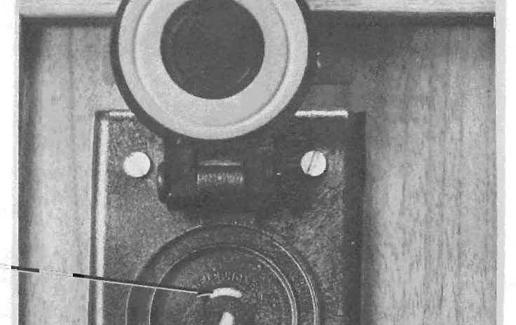


47 RNG --=~-- L WEATHERPROOF JACK FGURE 2
 en a: M w a: w")
 0 Q,.")
48 P fum A Y ~ u <t:.., z 0 0) en a: M w a: w ::> a: ~ ::::> <t: Co:' 2 LL. -~ Z 0 ~ C) 0 Q,. 6 Lt'l
 en w")


49 ~ (.) <t """) en w a: w en 2 qo o w t- c::: en ::::> ~ 2 u.. OJ w c::: ::::> t <t 2 2


50
51 TO C ) TO OTHER NETWOR K...L.l t EQU PM ENT MNATURE 6 POSTON JACK MNATURE 6 POSTON PLUG r ; ; 1 1 A ;. '-_ ! LLLLt 1 : ' TO REGSTERED TERMNAL EQUPMENT SMPLFED SCHEMATC - JACKS RJ11C AND RJ11W FGURE 6 TO NETWORK T LNE T CRCUT R A R A1 r'\ " TO OTHER EQUPMENT MNATURE 6 POSTON JACK MNATURE 6 POSTON PLUG i--:-""-r- -_ ~ 1.A, ! ~ Lt3t4tsll! ' ~ ART A1 / TO REGSTERED TERMNAL EQUPMENT SMPLFED SCHEMATC - JACKS RJ12C AND RJ12W FGURE 7
52 TO NETWORK T R LNE CRCUT T 'l A A1 n TO OTHER EQUPMENT 6 MNATURE ~- --~--... : i n : J A, A POSTON JACK MNATURE 6 POSTON PLUG r-r-r-r-f1-r-! 1- ~, ART A1 " TO REGSTERED TERMNAL EQUPMENT SMPLFED SCHEMATC - JACKS RJ13C AND RJ13W FGURE 8
53 TO NETWORK T1 R1 T2 R2 T1 R1 T2 R2 TO OTHER EQUPMENT MNATURE r ~- ~--... : 6 POSTON,i JACK 5 6: A ' , J-. MNATURE 6 POSTON PLUG l-_~-j--+~~-j----j "T2 R1 T1 R2 / TO REGSTERED TERMNAL EQUPMENT SMPLFED SCHEMATC - JACKS RJ14C AND RJ14W FGURE 9
54 TO SERES JACK SUCH AS RJ36 (NOTE) M MC R1 T1 PRELMNARY * SUBJ ECT TO EFFECTVE TARFF and/or FCC RULEMAKNG ---.,--_. --- ~ ,,----, 1 1 1, MNATURE POS TON : A \ A JACK :1 1 1 MNATURE 6 POSTON PLUG r , M AND MC :. t ttl : L-L1-3-1-~--~ ~t---J R1 TO REGSTERED TERMNAL EOUPMENT NOTE: M = MODE NDCATON MC = MODE NDCATON COMMON LEADS ARE TYPCALLY WRED TO AN RJ36X SERES JACK WHCH CAN BE USED TO CONNECT AN EXCLUSON KEY TELEPHONE SET AHEAD OF THE DATA EQUPMENT. SMPLFED SCHEMATC - JACK RJ16X Figure 10 TO NETWORK T R * SUBJECT TO EFFECTVE TARFF and/or FCC RULEMAKNG j--- --~---~---;--~ j MNATURE: ~::: : 6 POSTON JACK! A A A A : ~ ~ r j '1tl111' 1 1 MNATURE : : 6 POSTON PLUG: : \ T R TO REGSTERED TERMNAL EOUPMENT (NOTE) NOTE: EQUPMENT MUST COMPLY WTH ARTCLE 517 OF THE NATONAL ELECTRC CODE. SMPLFED SCHEMATC - JACK RJ17C Figure 11
55 TO NETWORK T R T R TO OTHER EQUPMENT TO MAKE BUSY CRCUT [ MB1 MB j ~ ~- 21 3! i 6 ~ J * SUBJECT TO EFFECTVE TARFF and/or FCC RULEMAKNG MNATURE 6 POSTON JACK MNATURE 6 POSTON PLUG MB R T MB1 \ TO REGSTERED TERMNAL EQUPMENT SMPLFED SCHEMATC - JACKS RJ18C Figure 12 TO NETWORK T [ T - R LNE A R CRCUT - A1 TO TELCO PROVDED EQUPMENT TO MAKE BUSY CRCUT MB 1 MB * SUBJECT TO EFFECTVE TARFF and/or FCC RULEMAKNG j--' _ ~--, --j MNATURE POSTON j 1\ JACK MNATURE 6 POSTON PLUG \ MB ART A 1 MB 1/ TO REGSTERED TERMNAL EQUPMENT SMPLFED SCHEMATCS - JACKS RJ19C Figure 13
56 *SUBJECT TO EFFECTVE TARFF and / or FCC RULEMAKNG TO NETWORK \ T1 R1 T2 R2 T3 R3, TO OTHER EQUPMENT j ~ i MNATURE 6 POS TON K JAC / / /\ / MNATURE 6 POSTON PLUG i i l---l---f--~--f---f---l--l T2 R1 T1 R2 R3j TO REGSTERED TERMNAL EQUPMENT SMPLFED SCHEMATC - RJ25C Figure 14
57 EXSTNG 4 PN JACK 4 PRONG TO MNATURE 6 POSTON JACK r------, , L.J MNATURE 6 POSTON PLUG '''------r / TO REGSTERED TERMNAL EQUPMENT SMPLFED SCHEMATC - FGURE 15 ADAPTER RJA1X EXSTNG 12PNJACK 12 PN PLUG TO MNATURE 6 POSTON JACK A~~~::--J21~1151~1----/7-1 'r--t:--,--,-, MNATURE 6 -,--f,11 -',' POSTON PLUG L J \ TO REGSTERED TERMNAL EQUPMENT SMPLFED SCHEMATC - ADAPTER RJA3X FGURE 16
58 , TO MNATURE 6 POSTON JACK '! ~ TO ~,",,",,", '...,, "' "',, r ,!'t ! L..J r , :' i L..J TO REGSTERED TERMNAL EQUPMENT TO REGSTERED TERMNAL EQUPMENT SMPLFED SCHEMATC - FGURE 17 ADAPTER RJA2X
59 3 POSTON WEATHERPROOF JACK 3 POSTON WEATHERPROOF PLUG TO REGSTERED TERMNAL EQUPMENT SMPLFED SCHEMATC - JACK RJ15C FGURE 18
60 f'relmnary TO NETWORK ( TO NETWORK ( T '"" TJTO OTHER EQUPMENT R R T J r-. T TO OTHER EQUPMENT R r R SMPLFED SCHEMATC - JACK RJ21X FGURE 19
61 TO ( NETWORK PRELMNARY T T LNE R CRCUT A R A1 TO OTHER EQUPMENT ~ 50 POSTON 50 MNATURE. RBBON JACK LNE i! 12 POSTON T R A A ~1 Q SMPLFED SCHEMATC - JACK RJ22X FGURE 20 NETWORK TO T. C T L- LNE R R CRCUT A A B- A1 A LNE POSTON MNATURE 3 50 RBBON ~ JACK - ~ 12 TO OTHER EQUPMENT POSTON T B. A A ,1 6 ;, SMPLFED SCHEMATC - JACK RJ23X FGURE 21
62 TO NETWORK T T R LNE CRCUT A A l R ~ A1 A1 TO OTHER EQUPMENT h5p LNE 50 POSTON -1- MNATURE 2 RBBON 3 JACK 4 5 '-- 27 POSTON T 26 R A,- 27 A1 T ~ SMPLFED SCHEMATC - JACK RJ24X FGURE 22
63 POSTON T R T R LNE JE.ill illb.l.jr.l -.ill- PR ~ MNATURE RBBON JACK 50 PROGRAMMNG RESSTOR UPTO 27 8 LNES TO 2 NETWORK 26 ~ 28 SMPLFED SCHEMATC - JACK RJ26X FGURE 23

 EQUPPED")
 REAR")

")
 N RJM4X")

64 RJ26S LNE CRCUT PLUG-N FRONT VEW RJ26X (COMMON EQUPMENT) EQUPPED WTH EGHT RJ26Ss (LNE CRCUTS) REAR VEW JACK FOR DATA EQ. PLUG FOR TELCO LNES FOUR RJ26Xs (COMMON EQUPMENT) EACH EQUPPED WTH EGHT RJ26Ss (LNE CRCUTS) N RJM4X (RACK MOUNTNG) FGURE 24 MULTPLE LNE DATA JACK

 N RJM3X (WALL MOUNTNG) FRONT VEW FGURE 25 MUlT1PlE")
65 PLUG FOR TELEPHONE LNE FACLTES JACK FOR DATA EQUPMENT SWTCH P,ER LNE FOR PROGRAMMED OR FXEO LOSS LOOP OPErTON REAR VEW RJ26X (COMMON EQUPMENT) EQUliPPED WTH EGHT RJ26S's (LNE CRCUTS) N RJM3X (WALL MOUNTNG) FRONT VEW FGURE 25 MUlT1PlE LNE DATA JACK
66 T POSTON LNE ill Jf.L PR PC R MNATURE RBBON JACK PROGRAMMNG RESSTOR 3 UPTO 8 LNES 27 TO 2 NETWORK 26 SMPLFED SCHEMATC - JACK RJ27X FGURE 26
67 TO NETWORK R 50 POSTON MNATURE RBBON JACK R TO OT~~ T T EQUPMENT ** ~ * 25 LNE POSTON CRCUT N OUT _#- T R T R t t C :::> PAl R C ~ PAR R 27 2 R T T "N" SDE ~ "OUT" SDE SMPLFED SCHEMATC - JACK RJ71C Figure 27 * SUBJECT TO EFFECTVE TARFF AND/OR FCC RULEMAKNG. ** A MANUAL BRDGNG PLUG S ALSO PROVDED BUT NOT SHOWN HERE. THE BRDGNG PLUG S NSERTED BY THE CUSTOMER WHEN THE REGSTERED SERES EQUPMENT S REMOVED. PLEASE NOTE THAT AN AUTOMATC RESTORAL ARRANGEMENT S UNDER DEVELOPMENT AND WLL ELMNATE THE NEED FOR THE BRDGNG PLUG. t THS CABLE S NOT TERMNATED N THE CONVENTONAL MANNER, (.E. PAR ON 26/1, ETC.) PAR ONE "N" S 26 & 27 AND PAR ONE "OUT" S 1 & 2.
68 R1 TO [T NETWORK R ----f , T1 TO TELCO WRNG MNATURE 8 POSTON SERES JACK SHORTNG BAR r r-+- SH 0 RT REMOV ED ON PLUG NSERTON MNATURE 8 POSTON PLUG SMPLFED SCHEMATC - JACK RJ31X FGURE 28
69 R1 T1 TO OTHER EQUPMENT MNATURE 8 POSTON SERES JACK SHORTNG BAR r ,-+-- SHO RT REMOVED ON PLUG NSERTON MNATURE 8 POSTON PLUG, t t t t t ttl ".. " ' :. - - " R1 R T T1 / TO REGSTERED TERMNAL EQUPMENT SMPLFED SCHEMATC - JACK RJ32X FGURE 29 TO ( NETWORK T R1 LNE C RCUT R ~... A1 1 A JTO OTHER EQUPMENT URE.'",!. '. '. /," { MNAT 8 POSTON SERES JACK SHORTNG BAR '{ SHORT REMOVED hi (" "\...(" - -n..r\...tv PLUG NSERTON / " ON MNATURE 8 POSTON ~ ~ : t t t t t t 1 t: PLUG l, R1 ART A1 T1, _/ TO REGSTERED TERMNAL EQUPMENT SMPLFED SCHEMATC - JACK RJ33X FGURE 30
70 PRELHNARY R1 TO NETWORK ("':"~~--4 LNE C RCU T ~R ""'" T1 TO OTHER EQUPMENT A A1 SH 0 RT NG SA R r :t. SHORT REMOVED 1 ON PLUG NSERTON :t-y-ft-r-fl-n._ ~ ART A1 T1 / MNATURE 8 POSTON SERES JACK MNATURE 8 POSTON PLUG TO REGSTERED TERMNAL EQUPMENT SMPLFED SCHEMATC - JACK RJ34X FGURE 31
71 R1 TO STATON SET TERMNALS T R A1 A TO STATON SET KEY PCK UP SHORT NG 1 2 BAR MNATURE 8 POSTON SERES JACK SHORT REMOVED ON PLUG NSE RT ON ~!r ~ r r r r! ri l ~ ' R1 ART A1 T1,,~ "'/ TO REGSTERED TERMNAL EQUPMENT MNATURE 8 POSTON PLUG M = MODE NDCATON MC= MODE NDCATON COMMON SMPLFED SCHEMATC - JACK RJ35X FGURE 32 M MC N E~ORK (...LT.L , MNATURE 8 POSTON SERES JACK )u TO T :...:...- OTHER JACKS RJ 16X, ETC. SHORTNG BAR r r--+-- SHO RT REMOVED ON PLUG NSERTON MNATURE r-r -~ ~--1-i 8 POSTON!! PLUG : : ' J R1 M R T MC T1 " / TO REGSTERED TERMNAL EQUPMENT * SUBJECT TO EFFECTVE and/or FCC RULEMAKNG SMPLFED SCHEMATC - JACK RJ36X FGURE 33
72 T2 TO NETWORK R2 T1 R2 EXR TO EXCLUDED SET R1 T2 EXT SH 0 RT NG ~ r--t---:l BAR SHORT REMOVED ON PLUG NSERTON !1! ill 1r ii J '\ EXR T2 R1 T1 R2 EXT /' TO REGSTERED TERMNAL EQUPMENT 8 MNATURE 8 POSTON JACK MNATURE 8 POSTON PLUG SMPLFED SCHEMATC - FGURE 34 JACK RJ37X
73 * SUBJECT TO EFFECTVE TARFF and/or FCC RULEMAKNG R1 TO NETWORK T R STRAP * T1 TO TELCO WRNG 2 MNATURE 8 POSTON SERES JACK MNATURE 8 POSTON PLUG SHORTNG BAR r t""'f-- SHO RT REMOV ED ON PLUG NSERTON r -, L.-J -f -f -f.-. -f -, r L_~' ~_.-J ' R1 R T T1..._ '/ TO REGSTERED TERMNAL EQUPMENT SMPLFED SCHEMATC - JACK RJ38X FGURE 35 * PROVDED BY THE TELEPHONE COMPANY.
74 NETWO~~ 0 ~ r , ~ 0 1 R (FLL)...c.:.':J 0 2 T (FLL) 3 M ~ 4 R (P) f ~ 5 T (P) PROGRAMMNG 6 MC PR RESSTOR ~ 0 8 PC MNATURE 8 - POSTON KEYED JACK L - J SMPLFED SCHEMATC JACK RJ41S FGURE 36

")


75 RJ41S (UNVERSAL DATA JACK) SHOWN WTH SPRNG LOADED DUST COVER CLOSED. RJ45S (PROGRAMMABLE DATA JACK) APPEARS THE SAME EXCEPT THAT SWTCH FOR PROGRAMMED OR FXED LOSS LOOP OPERATON S OMTED. RJ4lS SHOWN WTH PLUG NSERTED, KEYWAY FOR KEYED DATA PLUG CAN BE SEEN ON SDE OF JACK OPENNG FGURE 37 SNGLE LNE DATA JACKS
76 NETWO~~ ~ _---. r t L , o 1 o 2 1 o 3 M R (P) 5 T (P) t PROG~A_MMNG o 6 MC RESSTOR --"i 0 7 PR <; elo 8 PC MNATURE 8 - POSTON KEYED JACK f J 6Wl.FED SCHEMATC JACK RJ45S FGURE 38

 PLUS")

.")


77 RJ41M OR RJ45M S MPLEMENTED TH RJM2X (MULTPLE MOUNTNG) PLUS APPROPRATE NUMBER OF RJ41Ss OR RJ45Ss (SNGLE LNE DATA JACKS). RJM2X HOLDS 16 DATA JACKS AS SHOWN ABOVE. ////rrrrr rr RJM2X (MULTPLE MOUNTNG) WTH COVER CLOSED. MOUNTS ON WALL OR 19" OR (WTH ADAPTER PLATE) ON 23" RELAY RACK. FGURE 39 MULT PLE MOUNT'NG OF SNGLE LNE DATA JACK~
Product Guide Verizon Delaware LLC. Section 31 Delaware LLC Original Sheet 1. Connection With Certain Facilities of Others
 Delaware LLC Original Sheet 1 A. GENERAL Part 68 of the Federal Communications Commission's Rules and Regulations applies to customer premises equipment, with specified exceptions. Accordingly, regulations
MODEL CM-30. Technical Practice November 2002 Issue 4. Service Observing System 1. GENERAL 2. DESIGN FEATURES CONTENTS: Model CM-30
 Model CM-30 Technical Practice November 2002 Issue 4 MODEL CM-30 Service Observing System 1. GENERAL 1.01 The DEES CM-30 is a complete 30 line service observing system with integrated talk assist capability.
AT&T INDIANA GUIDEBOOK. PART 2 - General Terms and Conditions 1st Revised Sheet 1 SECTION 9 - Connections
 PART 2 - General Terms and Conditions 1st Revised Sheet 1 EXCHANGE SERVICES 1. General Provisions A. General Terminal equipment and communications systems provided by the customer may be connected at the
TLS-3A. Telephone Line Simulator. User Manual , Rev. B Covers Model TLS-3A-01
 User Manual TLS-3A Telephone Line Simulator 40-400-00010, Rev. B Covers Model TLS-3A-01 Teltone Corporation 22121-20th Avenue SE Bothell, Washington 98021-4408 USA Phone: 1-800-426-3926 or 425-487-1515
Part IV: Glossary of Terms
 Issue 9 November 2004 Spectrum Management and Telecommunications Policy Compliance Specification for Terminal Equipment, Terminal Systems, Network Protection Devices, Connection Arrangements and Hearing
INCOMING SELECTOR CIRCUITS FROM PANEL LOCAL, OFFICE TANDEM AND PANEL SENDER TANDEM OFFICES MANUAL TEST USING TEST SET ES OR ES
 BELL SYSTEM PRACTICES Plant Series INCOMING SELECTOR CIRCUITS FROM PANEL LOCAL, OFFICE TANDEM AND PANEL SENDER TANDEM OFFICES MANUAL TEST USING TEST SET ES-20150-01 OR ES-239844,,, I' I Issue 3, November,
Loop Current Holding Circuit
 XE1030 September 2004 SIP DAA Provides 3750 Volt Isolation Barrier Description Xecom s XE1030 is a complete DAA in a compact Singlein-Line package. It provides an ideal telephone interface for modem, audio
PagePac 20. ZoneMate 39 Service Manual For. Voice Paging System IS SM Issue 4, Nov. 1987
 ZoneMate 39 Service Manual For PagePac 20 Voice Paging System 999-500-205IS SM-722050-039 Issue 4, Nov. 1987 HARRIS CORPORATION Dracon Division 809 Calle Plano, Camarillo, California 93010, U.S.A. Telephone
Product Guide Verizon Delaware LLC. Section 11 Delaware LLC Original Sheet 1. Channels
 Delaware LLC Original Sheet 1 A. GENERAL A channel is defined as a transmission path between two points over which a single category of communications service is provided, usually furnished between different
23A TRANSMISSION MEASURING SET (J94023A) (DESCRIPTION)
 (DESCRIPTION)") BELL SYSTEM PRACTICES Central Office.Mainte>ance Description of Testing Equipment and Tools Toll Test Room Operation Description and Operating Principles of Systems and Equipment SECTION A702.625 Issue
BELL SYSTEM PRACTICES Central Office.Mainte>ance Description of Testing Equipment and Tools Toll Test Room Operation Description and Operating Principles of Systems and Equipment SECTION A702.625 Issue
PagePac 20 Voice Paging System ZoneMate 9 Service Manual
 999-500-204IS SM-722050-029 Issue 2 November 1987 PagePac 20 Voice Paging System ZoneMate 9 Service Manual ZoneMate 9 Service Manual For PagePac 20 Voice Paging System 999-500-204IS SM-722050-029 Issue
Supplement No Telephone PA P.U.C. - No. 14
 Supplement No. 39 - First Revised Sheet 1 Cancels Original Sheet 1 I. FOREIGN EXCHANGE SERVICE Foreign exchange service is not offered as a normal or customary form of telephone service. However, when
Part VI: Requirements for ISDN Terminal Equipment
 Issue 9 November 2004 Spectrum Management and Telecommunications Policy Compliance Specification for Terminal Equipment, Terminal Systems, Network Protection Devices, Connection Arrangements and Hearing
GSM-900 Contact ID Cellular Backup System Installation Manual
 GSM-900 Contact ID Cellular Backup System Installation Manual Rev. 1.01-08/11/08 Table of Contents Introduction... 3 1.0 Parts Needed to Complete this Installation... 3 2.0 Activation and Installation...
Figure FXS Front Panel. Figure FXS Front Panel
 Telecommunications Group Section 365-780-202 Equipment Issue 2 Fifth Printing, October 2006 12-Channel (3657-80) and 6-Channel (3657-81) 2-Wire Foreign Exchange Subscriber, Private Line Automatic Ringdown
Part I: Requirements for Terminal Equipment (TE) and Related Access Arrangements Intended for Direct Connection to Analog Wireline Facilities
 and Related Access Arrangements Intended for Direct Connection to Analog Wireline Facilities") Issue 9, Amendment 5 March 2016 Spectrum Management and Telecommunications Compliance Specification for Terminal Equipment, Terminal Systems, Network Protection Devices, Connection Arrangements and Hearing
Issue 9, Amendment 5 March 2016 Spectrum Management and Telecommunications Compliance Specification for Terminal Equipment, Terminal Systems, Network Protection Devices, Connection Arrangements and Hearing
Part VI: Requirements for Integrated Services Digital Network Terminal Equipment
 Issue 9, Amendment 1 September 2012 Spectrum Management and Telecommunications Compliance Specification for Terminal Equipment, Terminal Systems, Network Protection Devices, Connection Arrangements and
1.4 OPERATING INSTRUCTIONS
 1.4 OPERATING INSTRUCTIONS I -. 1.4.1 1.4.2 1.4.3 1.4.4 1.45 1.4.6 1.4.7 1.4.8 1.4.9 Station Nomenclature Station Lamp Signals DSS Console Lamp Signals System Tones Outside Calls - Outgoing 1.4.5.1 Seizing
5 yr. Station Level Paging Adapter. Model 300PBX-SC LINKS TELEPHONE TO SELECTONE OR PUBLIC ADDRESS SYSTEM. dedicated extension
 FEDERAL SIGNAL CORPORATION Station Level Paging Adapter Model 300PBX-SC LINKS TELEPHONE TO SELECTONE OR PUBLIC ADDRESS SYSTEM Paging by calling a dedicated extension Powered by a phone line connection
AT&T 12/88. PagePac 6 Plus Voice Paging System User and Installation Manual
 AT&T 12/88 PagePac 6 Plus Voice Paging System User and Installation Manual PagePac 6 Plus is recommended for the following telephone systems. PagePac 6 Plus COMPATIBILITY CHART AT&T TELEPHONE SYSTEM CONNECTION
RADIO SIGNAL SUPPRESSION FOR TELEPHONE SETS IDENTIFICATION, INSTALLATION, AND MAINTENANCE
 AT & T PRACTICE Standard AT & T 500-150-100 Issue 11, July 1984 RADIO SIGNAL SUPPRESSION FOR TELEPHONE SETS IDENTIFICATION, INSTALLATION, AND MAINTENANCE 1. GENERAL 1.01 This practice contains information
MEGAPLEX-2100 MODULE VC-16A. 16-Channel PCM/ADPCM Voice Module Installation and Operation Manual. Notice
 MEGAPLEX-2100 MODULE VC-1A 1-Channel PCM/ADPCM Voice Module Installation and Operation Manual Notice This manual contains information that is proprietary to RAD Data Communications No part of this publication
INTERNATIONAL TELECOMMUNICATION UNION DATA COMMUNICATION NETWORK: INTERFACES
 INTERNATIONAL TELECOMMUNICATION UNION CCITT X.21 THE INTERNATIONAL (09/92) TELEGRAPH AND TELEPHONE CONSULTATIVE COMMITTEE DATA COMMUNICATION NETWORK: INTERFACES INTERFACE BETWEEN DATA TERMINAL EQUIPMENT
Telephone / Background Music Interface Model VA-TBM. Installation and Use Manual
 Telephone / Background Music Interface Model VA-TBM Installation and Use Manual Notice Every effort was made to ensure that the information in this manual was complete and accurate at the time of printing.
XMU+ Environmental, Safety and Specifications
 XMU+ Environmental, Safety and Specifications Physical Unit Dimensions: Rack Width: Rack Space: Shipping Dimensions: Unit Maximum Weight: Shipping Maximum Weight: Power and Thermal Power Consumption: Heat
REGISTRATION INTERFACE BRIDGED MULTIPLE TIP AND RING ARRANGEMENTS
 BELL SYSEM PCCES & Co Provisional SECON -00-10 ssue, pril 1 1. GENEL 1.01 his section provides information on the standard wiring arrangements to be provided under the Federal Communications Commission
Wire Transmission Only with Sealing Current (4W TO W/SC) Channel Unit
 Channel Unit") Telecommunications Group Section 365 305 202 Equipment Issue 2 Second Printing, September 2000 3653 05 4-Wire Transmission Only with Sealing Current (4W TO W/SC) Channel Unit CONTENTS Complies with UL
Telecommunications Group Section 365 305 202 Equipment Issue 2 Second Printing, September 2000 3653 05 4-Wire Transmission Only with Sealing Current (4W TO W/SC) Channel Unit CONTENTS Complies with UL
PUERTO RICO TELEPHONE COMPANY, INC. Second Revision - Page K-1-1 Canceling First Revision - Page K-1-1. ADDITIONAL SERVICES TARIFF SCHEDULE (Cont.
 Second Revision - Page K-1-1 Canceling First Revision - Page K-1-1 25.1 Applicability TO THE PUBLIC TELEPHONE NETWORK This tariff applies to the Basic Interconnection Services provided by the Company,
GENERAL SUBSCRIBER SERVICES TARIFF Pembroke Telephone Company, Inc. Third Revised Contents Sheet 1 Cancels Second Revised Contents Sheet 1
 GENERAL SUBSCRIBER SERVICES TARIFF Pembroke Telephone Company, Inc. Section N Third Revised Contents Sheet 1 Cancels Second Revised Contents Sheet 1 N. CONNECTION WITH CERTAIN FACILITIES AND/OR EQUIPMENT
CAT-300DXL Repeater Controller Computer Automation Technology, Inc
 CAT-300DXL Repeater Controller Computer Automation Technology, Inc 4631 N.W. 31st Avenue, Suite 142 Fort Lauderdale, Florida 33309 Phone: (954) 978-6171 Fax: (561) 488-2894 Internet: http://www.catauto.com
Wire Line Amplifier
 Charles Industries, Ltd. Section 040 100 208 Equipment Issue 8 Third Printing, March 1999 401 00 4-Wire Line Amplifier CONTENTS PAGE Part 1. GENERAL.............................................................................
Summary of transmission parameters
 Meridian 1 Summary of transmission parameters Document Number: 553-2201-182 Document Release: Standard 11.00 Date: April 2000 Year Publish FCC TM Copyright 1984 2000 Nortel Networks All Rights Reserved
TCI Library-
 Section L of TELEPHONE EQUIPMENT & SUPPLIES CATALOG ISSUED SEPTEMBER, 1966 RECORDERS & ANNOUNCERS Recorder,-Announcers Type INT, Single-Channel, Fixed Message Length, Compact Transistorized Recorder-Announcers;
DATA SET 109B TYPE DESCRIPTION
 BELL SYSTEM Plant Series PRACTCES SECTON 312-802-100 ssue 1, December 1967 AT&TCo Swdard DATA SET 109B TYPE DESCRPTON 1. GENERAL 1.01 This section describes Data Set 109B type (109B1 and 109B2) physically
change (PABX) systems. There must, however, be isolation between and the higher voltage, transientprone
 systems. There must, however, be isolation between and the higher voltage, transientprone") Ring Detection with the HCPL-00 Optocoupler Application Note 0 Introduction The field of telecommunications has reached the point where the efficient control of voice channels is essential. People in business
Ring Detection with the HCPL-00 Optocoupler Application Note 0 Introduction The field of telecommunications has reached the point where the efficient control of voice channels is essential. People in business
MULTI-TONE GENERATOR V
 PagePac by Issue 1 V-5335500 INTRODUCTION The Multi-Tone Generator (MTG) is a compact, versatile multi-tone generator as well as a Night Bell for a Telephone System. Six different information tones plus
2 GHz Licence-exempt Personal Communications Service Devices (LE-PCS)
") RSS-213 Issue 2 December 2005 Spectrum Management and Telecommunications Radio Standards Specification 2 GHz Licence-exempt Personal Communications Service Devices (LE-PCS) Aussi disponible en français
RSS-213 Issue 2 December 2005 Spectrum Management and Telecommunications Radio Standards Specification 2 GHz Licence-exempt Personal Communications Service Devices (LE-PCS) Aussi disponible en français
DATA SETS 1 08D- AND 1 08E-TYPES SINGLE PRIVATE LINE STATION ARRANGEMENT USING DATA AUXILIARY SET 820D TEST PROCEDURES
 BELL SYSTEM PRACTCES AT&TCo Stondard. GENERAL 2. TEST EQUPMENT CARRER MONTORNG TEST A. Far-End Carrier B. Near-End Carrier CARRER SHFT TEST LOOP-BACK TEST DATA SETS 1 08D- AND 1 08E-TYPES SNGLE PRVATE
TELEPHONE USER GUIDE.-
 . ei nti4 w.. bun-auuw I I TELEPHONE USER GUIDE.- , Speaker Volume - Ring Tone & Intercom Voice Level 1 Dial Pad. Speaker Volume Dial Tone, \I^:^......A DPM Leve, Message Waiting/ - Flash Key _ Do Not
Application Note 1024
 HCPL-00 Ring Detection with the HCPL-00 Optocoupler Application Note 0 Introduction The field of telecommunications has reached the point where the efficient control of voice channels is essential. People
150-BAUD PRIVATE LINE CHANNELS
 BELL SYSTEM Plant Series PRACTCES SECTON 32-0-0 ssue, JUY 970 AT&TCo Standard 50-BAUD PRVATE LNE CHANNELS NTERFACE SPECFCATONS. DESCRPTON GENERAL.0 The purpose of this specification is to define the interface
S.C.C.-Va.-No Verizon Virginia LLC. in the State of Virginia as provided herein
 Original Title Regulations, Rates and Charges applying to the provision of Access Services within a Local Access and Transport Area (LATA) for connection to intrastate communications facilities for customers
Line Signalling Fundamentals
 Line Signalling Fundamentals Introduction This document refers to the types of signalling provided by and large by the PRX in its various forms across the range of delivered systems. Some of the concepts
Technical Equipment Specification
 STATE OF CALIFORNIA Office of the State Chief Information Officer Public Safety Communications Division Technical Equipment Specification Equipment Type: Transmitter/Receiver Mobile Relay/Base/Control
Product Guide Verizon Delaware LLC. Section 36B 1st Revised Sheet 1 Delaware LLC Cancels Original Sheet 1. Private Line
 1st Revised Sheet 1 Delaware LLC Cancels Original Sheet 1 1. General s are communications channels which connect customer premises, serving wire centers or combinations thereof. Channels may be provided
TELEPHONE SETS 881A102, , 881C102, 881A103, , 881C103, 881A104, , AND 881C104
 BELL SYSTEM PRACTCES AT & TCo Standard SECTON 53-2-18 ssue 3, January 1978 TELEPHONE SETS 881A12, 881812, 881C12, 881A13, 881813, 881C13, 881A14, 881814, AND 881C14 1. GENERAL 1.1 This section provides
Superseded by a more recent version INTERNATIONAL TELECOMMUNICATION UNION
 INTERNATIONAL TELECOMMUNICATION UNION ITU-T V.24 TELECOMMUNICATION STANDARDIZATION SECTOR OF ITU (10/96) SERIES V: DATA COMMUNICATION OVER THE TELEPHONE NETWORK Interfaces and voiceband modems List of
GDC 086R Issue 4, 10/17/97. Installation and Operation. Metroplex Flexi-Voice Plus Model MP General DataComm
 GDC 086R603-001-04 Issue 4, 10/17/97 Installation and Operation Metroplex 6000 Flexi-Voice Plus Model MP 6360 General DataComm Manual Revision History Shown below is a chronological listing of revisions
TECHNICAL. Time and Temperature Announcer DVA-TNT. Time and Temp Announcer
 TECHNICAL Practice TELECOM SOLUTIONS FOR THE 21ST CENTURY DVA-TNT Time and Temp Announcer August 31, 2001 Features Phone...715.386.8861 Time and Temperature Announcer The DVA-TNT Time and Temperature Announcer
Exercise 2-1. Battery Feed Power Supply
 Exercise 2-1 Battery Feed Power Supply When you have completed this exercise, you will be able to demonstrate how the central office supplies power to analog telephone sets. A telephone set requires electrical
Radio Systems Policy for Radio Paging with Special Reference to the 900 MHz Band
 May 1989 Spectrum Management Radio Systems Policy Radio Systems Policy for Radio Paging with Special Reference to the Aussi disponible en français PR-011 Table of Contents 1. Intent... 1 2. Background...
Zone Paging System. Model PCM2000. Features. Technical Specifications
 Zone Paging System Model PCM2000 Features One-zone to 99-zones of simultaneous highpower and low-power paging Up to 32 paging zone groups Universal telephone interface designed for direct connection to
RADIO SIGNAL SUPPRESSION FOR TELEPHONE SETS
 BELLSYSTEM PRACTICES SECTION500-150-11X) AT&TCo Standard Issue 7, January 1974 RADIO SIGNAL SUPPRESSION FOR TELEPHONE SETS 1. GENERAL Transistors in amplifiers of some networks and handsets 1.01 This section
Ambient Level Controller
 Ambient Level Controller Installation and Use Manual Issue 1, October 1999 1999 Bogen Communications, Inc. All rights reserved. 54-2028-01 9910 Model: LUALC PEC Code: 5335-621 COM Code: 408184273 Select
INTERNATIONAL TELECOMMUNICATION UNION DATA COMMUNICATION OVER THE TELEPHONE NETWORK
 INTERNATIONAL TELECOMMUNICATION UNION ITU-T V.24 TELECOMMUNICATION (03/93) STANDARDIZATION SECTOR OF ITU DATA COMMUNICATION OVER THE TELEPHONE NETWORK LIST OF DEFINITIONS FOR INTERCHANGE CIRCUITS BETWEEN
PART 15 - Dedicated Telecommunications Services Original Sheet 1 SECTION 2 - Channel Services
 PART 15 - Dedicated Telecommunications Services Original Sheet 1 1. VOICE GRADE SERVICES A. GENERAL Additional terms and conditions applicable to Special Access Services may be found in Part 2, Section
Qt 600. Sound Masking - Paging - Music Installation Guide. Purchase date: Install date: MAC Address
 Qt 600 Sound Masking - Paging - Music Installation Guide Contents TOPIC System Overview Installing The Control Module Installing Qt PRO Emitters Connecting to Software Installing Audio Inputs Installing
VC-4/4A, VC-8/8A, VC-16 4/8/16-Channel PCM and ADPCM Voice Modules
 4, 8 or 16 analog voice channels using 64 kbps toll-quality PCM encoding; 24/32 kbps ADPCM encoding option for 4- and 8-channel modules E&M, FXS or FXO interface options Caller ID A-law or μ-law companding
INTERCONNECTING DEVICES COMMON EQUIPMENT 75A CONTROL UNIT
 BSP 463-300-112-i01_1973-11.01.jpg Scanned by Frank Harrell (CowboyFrank) Castle Rock. Colorado Feb 23.2016 21:15:56 BELL SYSTEM PRACTCES AT&TCo Standard SECTON 463-300-112 ssue 1, November 1973 NTERCONNECTNG
Exercise 1-4. Pulse Dialing
 Exercise 1-4 Pulse Dialing When you have completed this exercise, you will be able to demonstrate pulse dialing, an older signaling technique to transmit telephone numbers to central offices using a series
CYG2111. Cybergate TM DAA INTEGRATED CIRCUITS DIVISION. Description. Features. Applications. Approvals. Ordering Information. Typical Application
 Cybergate TM DAA Features Low Distortion Transformer Signal Coupling Complete Ringing Detector Circuit Low Power Hook Switch Electronic Inductor/Gyrator Circuit Surge Protection V.32 bis/v.34 Compatible
SETUP and OPERATING MANUAL ADVANCED MULTI-CHANNEL VEHICLE INTERCOM SYSTEM (AMCVIS)
") SETUP and OPERATING MANUAL Sept 23, 2010 Rev D ADVANCED MULTI-CHANNEL VEHICLE INTERCOM SYSTEM (AMCVIS) with DIGITAL CREW CONTROL and RADIO BRIDGING The AMCVIS was designed, manufactured and is supported
SETUP and OPERATING MANUAL Sept 23, 2010 Rev D ADVANCED MULTI-CHANNEL VEHICLE INTERCOM SYSTEM (AMCVIS) with DIGITAL CREW CONTROL and RADIO BRIDGING The AMCVIS was designed, manufactured and is supported
W FXS LS/GS Channel Unit 600 Ohms
 Telecommunications Group Equipment Issue 1 Second Printing, September 2000 3657 03 FXS LS/GS Channel Unit 600 Ohms CONTENTS PAGE Part 1. GENERAL.............................................................................
PagePac Plus AmpliCenter V A/V A Installation and Use
 Issue 1 Important Safety Instructions PagePac Plus AmpliCenter V-5328100A/V-5328300A Installation and Use 1. Read these instructions. 2. Keep these instructions. 3. Heed all warnings. 4. Follow all instructions.
VC-4/4A, VC-8/8A, VC-16
 Data Sheet Megaplex-4, Megaplex-2100/2104 VC-4/4A, VC-8/8A, VC-16 E&M, FXS or FXO options Caller ID A-law or µ-law companding Optional inband signaling with A-law encoded channels PCM (64 kbps) and ADPCM
AT&T SERVICE MANUAL. PagePac VS (AT&T VERSION) INSTALLATION
 INSTALLATION") AT&T SERVICE MANUAL PagePac VS (AT&T VERSION) INSTALLATION AT&T SERVICE MANUAL PagePac* VS INSTALLATION SM 722994 004 Issue 1, *Registered Trademark of Harris Corporation Dracon Division Copyright HARRIS
AT&T SERVICE MANUAL PagePac VS (AT&T VERSION) INSTALLATION AT&T SERVICE MANUAL PagePac* VS INSTALLATION SM 722994 004 Issue 1, *Registered Trademark of Harris Corporation Dracon Division Copyright HARRIS
ACCESS SERVICE TARIFF S.C.C.-Va.-No Verizon Virginia LLC Section 7 1st Revised Page 1 Cancels Original Page 1 SPECIAL ACCESS SERVICE
 1st Revised Page 1 Cancels Original Page 1 7.1 General Special Access Service provides a transmission path to connect customerdesignated locations*, either directly or through a Telephone Company hub where
CYG20xx. Cybergate TM DAA INTEGRATED CIRCUITS DIVISION. Description. Features. Approvals. Ordering Information. Applications.
 Cybergate TM DAA Features Low Distortion Transformer Signal Coupling (0.0% max) Complete Ring Detector Circuit Low Power Hook Switch Electronic Inductor/Gyrator Circuit Surge Protection Transient Protection
SIN 57 Issue 2.4 May 2018
 SIN 57 Issue 2.4 May 2018 Suppliers' Information Note For The BT Network BT KiloStream X.21 Interface Service Description Each SIN is the copyright of British Telecommunications plc. Reproduction of the
TOA NEW 900 SERIES MIXER PREAMPLIFIER M-900A
 Operation Instruction Manual TOA NEW 900 SERIES MIXER PREAMPLIFIER M-900A Features General Description 1 6-channel mixer preamplifier 2 Wide frequency response; 20 20,000Hz, ±1dB 3 Low distortion and noise
) #(2/./53 $!4! 42!.3-)33)/.!4! $!4! 3)'.!,,).' 2!4% ()'(%2 4(!. KBITS 53).' K(Z '2/50 "!.$ #)2#5)43
 #(2/./53 $!4! 42!.3-)33)/.!4! $!4! 3)'.!,,).' 2!4% ()'(%2 4(!. KBITS 53).' K(Z '2/50 !.$ #)2#5)43") INTERNATIONAL TELECOMMUNICATION UNION )454 6 TELECOMMUNICATION STANDARDIZATION SECTOR OF ITU $!4! #/--5.)#!4)/. /6%2 4(% 4%,%(/.%.%47/2+ 39.#(2/./53 $!4! 42!.3-)33)/.!4! $!4! 3)'.!,,).' 2!4% ()'(%2 4(!.
INTERNATIONAL TELECOMMUNICATION UNION )454 6 TELECOMMUNICATION STANDARDIZATION SECTOR OF ITU $!4! #/--5.)#!4)/. /6%2 4(% 4%,%(/.%.%47/2+ 39.#(2/./53 $!4! 42!.3-)33)/.!4! $!4! 3)'.!,,).' 2!4% ()'(%2 4(!.
Smoking and any food or drinks are not permitted in the Applications Lab!
 Pre-Lab Activities: None 220 Lab A Electrical Properties of Transmission Systems and the Local Loop Purpose of the experiment: Experiment with a telephone and view its properties under various different
Wilcom MODEL T136BSBZW CIRCUIT TEST SET. Operating Instructions
 Wilcom MODEL T136BSBZW CIRCUIT TEST SET Operating Instructions T136BSB Current Test Set Operating Instructions 811-230-007 February 2007 Copyright (c) 2007 Wilcom All Rights reserved Wilcom reserves the
VC-6 6-Channel PCM Voice Module MEGAPLEX-2100 MODULE
 Installation and Operation Manual VC-6 6-Channel PCM Voice Module MEGAPLEX-2100 MODULE MEGAPLEX-2100 MODULE VC-6 6-Channel PCM Voice Module Installation and Operation Manual Notice This manual contains
1825 Duet Plus Installation Guide
 1825 Duet Plus Installation Guide Algo Communication Products Ltd. www.algosolutions.com 90-00046B - 1 - Table of Contents Release 2 Updates - Feb. 2012... 3 Quick Install for Dry Contact Ringing... 4
ACCESS CONTROL CENTER RADIO ACCESS SYSTEM INTERCONNECTION
 ACCESS CONTROL CENTER RADIO ACCESS SYSTEM INTERCONNECTION Model ACC2500 Desktop System Controller Existing PBX or PSTN Extension or Trunk Port No. 12612-002 Interface Assembly Customer-provided Cat 5e/6
CYG2020/CYG2021 RING HOOKSWITCH LOOPI OH RING RING RING R_LIM
 CYG0XX Cybergate TM Features Low distortion transformer signal coupling (0.0% max) Complete ring detector circuit Low power hookswitch Electronic inductor/gyrator circuit Surge protection Transient protection
Product Guide Verizon Pennsylvania Inc. Section 14A Verizon Pennsylvania Inc. Original Sheet 1 TELPAK CHANNELS AND SERVICES
 Original Sheet 1 A. GENERAL 1. This Guide Section applies only to those channels and services which the customer has specified be furnished as Telpak channels and services. Effective October 24, 1985,
CENTURYLINK OPERATING COMPANIES TARIFF F.C.C. NO. 10 INTERSTATE INTRALATA MESSAGE TELECOMMUNICATIONS SERVICE
 Cancels Embarq Local Operating Companies Tariff F.C.C. No. 2 Original Title Page 1 (x) Interstate IntraLATA Message Telecommunications Service Regulations and Schedules of Charges Applying to interstate
UPLINK MODEL 2540 CDMA WIRELESS ALARM COMMUNICATOR DEALER INSTALLATION, OPERATIONS AND PROGRAMMING GUIDE PRODUCT ID # UP254001
 To download a copy of this manual go to Account Access (Dealer Login) at www.uplink.com. UPLINK MODEL 2540 CDMA WIRELESS ALARM COMMUNICATOR PRODUCT ID # 202132UP254001 DEALER INSTALLATI, OPERATIS AND PROGRAMMING
AM48 XT & AM48e XT Family of Products
 AM48 XT & AM48e XT Family of Products AM-44 XT The AM-4 Series of Hand-Held Transmission Test Sets There are four models in the AM-4 series family. They are AM-44 XT and AM-48 XT which comply with Bell
QWEST Communications International Inc. Technical Publication
 QWEST Communications International Inc. Technical Publication Intelligent Network Channel Terminating Equipment Protocol Copyright 1992, 2001 77325 QWEST Communications International Inc. Issue C All Rights
Installation Guide & User Manual
 Installation Guide & User Manual TeleTalker Telephone Enhanced Amplified Telephone System, Model TEL 004 MAN 032B TeleTalker Telephone Enhanced Amplified Telephone System, Model TEL 004 Installation Guide
PagePac Plus AmpliCenter V A - (D300A) V A - (D100A) V (D40) Installation and Use
 V A - (D100A) V (D40) Installation and Use") Issue 3 IMPORTANT SAFETY INFORMATION: PagePac Plus AmpliCenter V-5328300A - (D300A) V-5328100A - (D100A) V-5328040 - (D40) Installation and Use 1. Read these instructions. 2. Keep these instructions. 3.
Issue 3 IMPORTANT SAFETY INFORMATION: PagePac Plus AmpliCenter V-5328300A - (D300A) V-5328100A - (D100A) V-5328040 - (D40) Installation and Use 1. Read these instructions. 2. Keep these instructions. 3.
Specification PTC 281: Telecom Requirements for Customer-connected
 Specification PTC 281: 2008 Telecom Requirements for Customer-connected ADSL2+ Line Filters Access Standards Telecom New Zealand Limited Wellington New Zealand July 2008 CONTENTS Page Table of Diagrams
.2 Section Waste Management and Disposal..4 Section Electrical General Requirements.
 Issued 2006/08/01 Section 16724 Public Address System Page 1 of 8 PART 1 GENERAL 1.1 RELATED SECTIONS.1 Section 01330 Submittal Procedures..2 Section 01355 Waste Management and Disposal..3 Section 01780
Data Channel Interface W/SC Generator
 Telecommunications Group Section 730 546 203 Equipment Issue 3 Second Printing, October 1999 7305 46 Data Channel Interface W/SC Generator CONTENTS PAGE Part 1. GENERAL.............................................................................
EasyAssist. Direct to Radio Call Button. Operating Manual
 EasyAssist Direct to Radio Call Button Operating Manual Table of Contents NOTES: Contents Introduction...4 RF Safety and FCC Information...5 Industry Canada Information...6 Safety and Information...7 EasyAssist
KMA 24 and KMA 24H Bendix/King Audio Control Systems
 KMA 24 and KMA 24H Bendix/King Audio Systems Compact TSO d consoles make audio control push button simple Push button simplicity puts complete, flexible audio control right at your fingertips with Bendix/King
TECHNICAL. ZPI-4 Four Zone Paging Interface. Four Zone Paging Interface
 TECHNICAL Practice TELECOM SOLUTIS FOR THE ST CENTURY ZPI- Four Zone Interface August 6, 00 Features Four Zone Interface The ZPI- features balanced audio circuitry throughout for low noise and compatibility
CX-A6 Amplifier Installation & User Guide V9.0
 CX-A6 Amplifier Installation & User Guide V9.0 Cloud Electronics Limited 140 Staniforth Road, Sheffield, S9 3HF England Tel + 44 (0) 114 244 7051 Fax + 44 (0) 114 242 5462 E-mail info@cloud.co.uk Web site
AT&T INDIANA GUIDEBOOK. PART 17 - ISDN Services SECTION 2 - ISDN Prime Services. 1st Revised Sheet 1 Cancels Original Sheet 1 1. ISDN PRIME SERVICE
 PART 17 ISDN Services SECTION 2 ISDN Prime Services 1st Revised Sheet 1 Cancels Original Sheet 1 1. ISDN PRIME SERVICE A. Description ISDN (Integrated Services Digital Network) Prime is a digital business
E-800 power amplifier. user manual
 E-800 power amplifier user manual Musikhaus Thomann e.k. Treppendorf 30 96138 Burgebrach Germany Telephone: +49 (0) 9546 9223-0 E-mail: info@thomann.de Internet: www.thomann.de 03.06.2013 Table of contents
Bell System Voice Communications
 PUB 48005 Bell System Voice Communications TECHNICAL REFERENCE Functional Product Class Criteria Telephones January 1980 DIRECTOR-BUSINESS PREMISES ENGINEERING DATA AND SPECIAL SYSTEMS @American Telephone
4A SPEAKERPHONE SYSTEM
 BELL SYSTEM PRACTCES AT&TCo Standard SECTON 512-7-lOD ssue 2 September 1974 4A SPEAKERPHONE SYSTEM \ 1. DENTFCA TiON 1.1 The 4A speakerphone system is a hands-free voice switched system for use as a telephone
Part V: Requirements and Test Methods for Magnetic Output from Handset Telephones for Hearing Aid Coupling
 Issue 9 November 2004 Spectrum Management and Telecommunications Policy Compliance Specification for Terminal Equipment, Terminal Systems, Network Protection Devices, Connection Arrangements and Hearing
Stealth Labs GSM 1650 Cellular Backup System Installation Manual
 Stealth Labs GSM 1650 Cellular Backup System Installation Manual Rev. 1.04 11/29/07 Table of Contents Introduction... 3 1.0 Parts Needed to Complete this Installation... 3 2.0 Activation and Installation...
POT Line to Remote Phone
 OPX PO Line to Remote Phone FXO In this application the customer uses the specified ADRAN equipment to extend a plain old analog telephone line to a remote location (Off Premise Extension). he customer
EUROPEAN pr ETS TELECOMMUNICATION February 1996 STANDARD
 FINAL DRAFT EUROPEAN pr ETS 300 118 TELECOMMUNICATION February 1996 STANDARD Second Edition Source: ETSI TC-TE Reference: RE/TE-05049 ICS: 33.020 Key words: PSTN, modems Public Switched Telephone Network
Includes Instructions on Installation, Programming, and Troubleshooting for use with G-TEL Payphones with Model Series-5 Elcotel Smart Chassis
 Includes Instructions on Installation, Programming, and Troubleshooting for use with G-TEL Payphones with Model Series-5 Elcotel Smart Chassis Version 2.0 TABLE OF CONTENTS INTRODUCTION... 2 IMPORTANT