Double Penetration (DP) Filter nonlinearcircuits
|
|
|
- Cory Harper
- 6 years ago
- Views:
Transcription
1 Double Penetration (DP) Filter nonlinearcircuits Build guide & BOM Vers.1 18/1/2014 Large schematic is here - Module description - Muffs thread - This PCB is very dense with a lot of 1206 SMD components. It is not suitable for beginners. If you are new to soldering SMD, have a look at some vids on You-tube to see how it is done. Once you learn the techniques you will find it quicker and easier than thru-hole..except for the chip It was designed to work on +/-12V but has been tested and works okay on +/-15V. Most likely some resistor values will need to be changed to get optimum performance; these are noted in the BOM. You can just build it with the values shown and it will work fine, but this is DIY and you should experiment!!! Building Solder on all of the SMD components 1 st I usually solder on all of the SMD components on the top (component side) of the PCB first and then turn it over to solder on the ones on the solder side. Then solder on the TL074. Once this is done just solder on the rest of the components in the usual order; resistors, caps, trannies, etc. Unlike my other PCBs, this one is marked with component numbers rather than values (except for a few parts), this is because these filters can be built in different ways. There have been many ladder variations over the years. Also, some resistor values could possibly be tweaked to get better performance. These are noted in the BOM, if you think an alternative value is better, please share the info with others in the Muffs thread or let me know and I will update this guide. I solder SMD with a pair of fine tweezers and a regular Hakko soldering iron. 1. solder one pad, just a little bit 2. push the component into position with the tweezers, or finger for the brave (Ken!) 3. reheat the solder and slide the component onto the pad 4. wait for it to cool 5. solder the other pad
2 6. wait for it to cool 7. add a bit of solder to the 1 st pad to make it look nice 8. done For the chip, it is similar; 1. solder a corner pad 2. put the chip in position 3. reheat the solder and slide the chip onto the pad 4. make sure all the pins are lined up on their respective pads 5. do not try to twist the chip once the 1 st pin is soldered as you can easily lift the pad or bend the pin, reheat the solder a little if you need to adjust its position. 6. once the chip is nicely lined up, put a bit of solder on the diagonally opposite corner pin 7. wait for it to cool 8. solder up the other pins. There are a few techniques to do this, check it on You-tube, I just solder one pin at a time and wait for it to cool. 9. use solder-wick to remove any shorts between pins 10. done B O M 2 decoupl ing caps 100n marked 100n on PCB 1206 C1 100n 1206 C2 100n (33n) () = tb303 version C3 100n (33n) C4 100n (33n) C5 100n (18n) C10 C11 C12 C13 C14 C15 C16 C17 C18 C19 100n 100n 100n 100n C6 C20 C7 C21 C8 C9 D1 D4 signal diodes 1N4148 or 1N914, matched
3 for V on, if you like R10 2K2 Q1, 2 offset opt 1-4 dual photocoupler TLP521-2 from Futurlec R11 100K 1206 R12 10k 1206 R13 10k 1206 Pots k 50k - 100k ok R14 10k 1206 R15 470k Q1, Q2, Q3, Q5, Q6, Q7, BC547 NPN Q4, Q8 BC557 PNP RESISTORS: R1 100R 1206 R2 1K 1206 R3 1K vary to get Trans ladder CV range correct as no tune trimpot R4 150K adjust to centre CV for Trans ladder R5 100K 1206 R6 100K 1206 R7 1K 1206 R8 1K 1206 R9 6K2 MAYBE adjust (10k?) Trans ladder R16 470k R17 100k 1206 marked c on the PCB R18 100k 1206 adjust to change amplitude of sum out R19 1k 1206 (marked as 1k on pcb) R20 100k 1206 R21 100k 1206 adjust to change amplitude of diff output R22 100k 1206 adjust to change amplitude of diff output R23 100k 1206 marked c on the PCB R24 1k 1206 marked as 1k on pcb R25 1k 1206 (marked as 1k on pcb) R26 1k 1206
4 R27 1k 1206 R28 10k 1206 R29 2k R39 10k 1206 R40 10k 1206 R41 10k 1206 R30 47k 1206 R31 47k 1206 R42 R43 470k 470k R32 1k 1206 R33 10k 1206 R34 1k vary to get CV range correct as no tune trimpot R44 1k 1206 R45 100k 1206 R46 10K 1206 R47 100K 1206 R35 100k 1206 R36 100k R (2) or link R37 150k adjust to centre CV for diode ladder switch DPDT on - on U1234 TL074 SOIC R38 100k indicates SMD, otherwise it is a thru-hole component. C2-C5, C12-C15 all 4.5mm pin spacing All electros are 2mm pin spacing Usually these filters have matched transistors or diodes in the ladders, not practical here, at least match Q1 with Q2 and Q5 with Q6, also match D1-D4. or don t bother Pots should be 9mm upright, these ones from Tayda are fine - or they have a cheaper plastic shaft version.
5 Dual photocoupler there are many of these available. Maybe some work better than others; I only tried the TLP521-2 from Futurlec. The main point is the pinout matches the PCB: If you want to try other types, feel free to check the specs with me or on Muffs first. Some photocouplers have unusual parameters, though most are about the same. Here are some to try; the TLP series are near end of life, but still many around. The BAD list will not work, usually the pinout is different or it has an AC input (you want DC). If you have the luxury of choice, look for ones with the lowest voltage drop on the LEDs. The list below is not exhaustive, just ones I found on RS Components, manufacturer websites and the google machine. At this stage I have only tried the TLP GOOD ILD615 BAD TLP620 ACPL-827 HCPL TLP521-2 KB827 K827PH LTV827 LTV826 ISP827 TLP504A ILD74 ISD1, ISD5, ISD74 CNY74-2H MCT6 KB824
6 TLP321-2 TLP621-2 TLP624-2 ISD20x LTV-824 ISP824 TLP628-2 TLP629-2 MCT9001 LDA203 SDT800 TIL918

7 Panel is 12HP

8 red Difference out orange Sum out yellow diode ladder out light blue (2) Diode ladder inputs blue Transistor ladder input dark blue Transistor ladder CV1 purple Transistor ladder CV2 brown Diode ladder CV1 pink Diode ladder CV2 green transistor ladder out There are two ground pins marked gnd, one is next to the difference out and the other is next to the Transistor ladder CV inputs

9 The Transistor ladder input is sitting alone in the middle of the PCB. If using IDC connectors for the wiring it would be easiest to solder this one in before installing C4, otherwise it is a pretty tight fit. it really depends on the size of your C4. Wiring for the Q swap switch. Make sure the red wires are connected to the holes as shown.
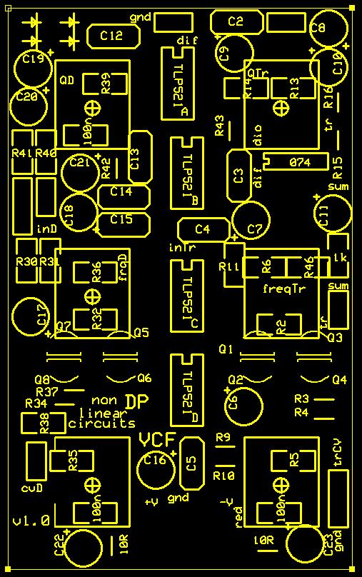
10 PCB silkscreen

11 Back of PCB
12 Using this module Firstly, the transistor ladder will not work by itself. The diode ladder can be used as a stand-alone filter if desired. The audio signal to the diode ladder is fed to the transistor ladder as infra-red light by the photo-couplers. So in general use, just use the diode ladder inputs, for most pot settings you will be able to get filtered signals from all four outputs. The freq cut-off and Q of each filter can be modulated independently. So why have an input for the transistor ladder? If you insert an audio signal here it will have an FM effect on the audio signal coming in from the diode ladder, so consider it another modulation input. If the signal on the transistor input is of a similar frequency to the one on the diode filter input, you can get some pretty good filtered harmonics happening. The Q swap switch swaps the Q feedback paths of the 2 filters. The effect is quite brutal though can be tamed with careful tweaking of the Q pots. At some settings you will get chaos (unverified, the maths is beyond me) but the module will take on a life of it s on. Sometimes you will hear the original audio signal, other times it will glitch away or no sound at all can be heard. This behaviour can of course be semi-controlled by CV.
nonlinearcircuits QUO/LPF build notes version 2 11 April 2014
 nonlinearcircuits QUO/LPF build notes version 2 11 April 2014 This circuit is based on the 4 pole LPF in Electronotes 41, tho has been subject to a number of tweaks and prods to bring it to where it is
build info nonlinearcircuits
 It s 555 resonator build info nonlinearcircuits BOM BC547 10 npn marked n on PCB see notes BC557 10 pnp- marked p on PCB see notes 555 IC 5 TL072 2 TL074 1 power connector 0.156 1 Molex 3 pin 100k pots
nonlinearcircuits NULL-A 2 Build & BOM
 nonlinearcircuits NULL-A 2 Build & BOM Null-A 2 is an all-in-one analogue synth packed into 42HP. It features: 2 VCOs 1 state variable VCF 1 ladder VCF 1 VC Delay 3 VCAs 2 LFOs Mixer Headphone amp Sequencer
LunarBlast v1.0. Optical Tremolo. Description:
 LunarBlast v1.0 Optical Tremolo Description: Based on the venerable DIY Tremulus Lune classic circuit, www.madbean.com forum member CultureJam created this awesome sounding tremolo dubbed the Shoot the
Penrose Quantizer Assembly Guide
 Penrose Quantizer Assembly Guide Schematic and BOM The schematic can be found here: www.sonic-potions.com/public/penrosequantizerschematic.pdf The BOM is available at google docs: Link to BOM Prepare the
Eurorack DIY Kit Instructions. All Thonk kits are sold under our standard Terms and Conditions -
 MA VCA OVERVIEW For the most recent version of this document please visit http://thonk.co.uk/documents/ma/ For all technical support please visit http://bit.ly/1tl78e0 on Muffwiggler. All Thonk kits are
V6.2 SoftRock Lite Builder s Notes. November 17, 2006
 V6.2 SoftRock Lite Builder s Notes November 17, 2006 Be sure to use a grounded tip soldering iron in building the v6.2 SoftRock circuit board. The soldering iron needs to have a small tip, (0.05-0.1 inch
N3ZI Kits General Coverage Receiver, Assembly & Operations Manual (For Jun 2011 PCB ) Version 3.33, Jan 2012
 Version 3.33, Jan 2012") N3ZI Kits General Coverage Receiver, Assembly & Operations Manual (For Jun 2011 PCB ) Version 3.33, Jan 2012 Thank you for purchasing my general coverage receiver kit. You can use the photo above as a
N3ZI Kits General Coverage Receiver, Assembly & Operations Manual (For Jun 2011 PCB ) Version 3.33, Jan 2012 Thank you for purchasing my general coverage receiver kit. You can use the photo above as a
Warm Tube Clock. Before we start, please make sure that you have all required parts that come for the IN-16 Nixie shield :
 Warm Tube Clock Assembly Instructions for the IN-16 Nixie shield Introduction Congratulations on your purchase of OSH Nixie Tube Clock. In this document you will see all steps you need to follow in order
Assembly Manual for VFO Board 2 August 2018
 Assembly Manual for VFO Board 2 August 2018 Parts list (Preliminary) Arduino 1 Arduino Pre-programmed 1 Faceplate Assorted Header Pins Full Board Rev A 10 104 capacitors 1 Rotary encode with switch 1 5-volt
Wiring Manual NEScaf April 2010 (August 2006)
") Wiring Manual NEScaf April 2010 (August 2006) Switched Capacitor Audio Filter The NEScaf is a switched capacitor audio filter (acronym SCAF) built around a building-block type filter chip. The NEScaf will
Wiring Manual NEScaf April 2010 (August 2006) Switched Capacitor Audio Filter The NEScaf is a switched capacitor audio filter (acronym SCAF) built around a building-block type filter chip. The NEScaf will
Electric Druid Flangelicious Flanger Project
 Electric Druid Flangelicious Flanger Project (Using either 4KNOBFLANGE or MULTIFLANGE chips) Overview! 2 Build Instructions! 2 Populate the PCB! 2 1N4148 Diodes! 2 Resistors! 2 Cup of tea and soldering
SoftRock v6.0 Builder s Notes. May 22, 2006
 SoftRock v6.0 Builder s Notes May 22, 2006 Be sure to use a grounded tip soldering iron in building the v6.0 SoftRock circuit board. The soldering iron needs to have a small tip, (0.05-0.1 inch diameter),
BMC055. Sallen-Key Voltage Controlled Filter Last updated
 BMC055. Sallen-Key Voltage Controlled Filter Last updated 0-6-208 If you have any questions, or need help trouble shooting, please e-mail Michael@Bartonmusicalcircuits.com I What The Knobs And Jacks Do
NEW WAVE CV GENERATOR Build Document last updated september 2017 for PCB version 1.0
 NEW WAVE CV GENERATOR Build Document last updated september 2017 for PCB version 1.0 The New Wave is a Control Voltage Generator. It has two LFO's (low frequency oscillators) and four different output
Value Location Qty Potentiometers C1M Distortion 1 A10k Volume 1. Footswitch 3PDT SW1 1. Jacks 1/4 Mono 2 DC Power 1
 Distortion BUILD INSTRUCTIONS Thank you for your purchase of our Distortion+ kit! We have completely redesigned our entire line of kits to be the most user friendly, while still maintaining their same
SoftRock v5.0 Builder s Notes. December 12, Building a QSD Kit
 SoftRock v5.0 Builder s Notes December 12, 2005 Building a QSD Kit Be sure to use a grounded tip soldering iron in building the QSD board. The soldering iron needs to have a small tip, (0.05-0.1 inch diameter),
The Sudden Storm & Rexwood 1000W Kits. from QRPme. Builder s Guide. Version 6.2. for. Sudden Storm ][ ver.6 Rexwood 1000W ver.6. Updated 12/18/2017
![The Sudden Storm & Rexwood 1000W Kits. from QRPme. Builder s Guide. Version 6.2. for. Sudden Storm ][ ver.6 Rexwood 1000W ver.6. Updated 12/18/2017](/thumbs/89/98806822.jpg "The Sudden Storm & Rexwood 1000W Kits. from QRPme. Builder s Guide. Version 6.2. for. Sudden Storm ][ ver.6 Rexwood 1000W ver.6. Updated 12/18/2017") The Sudden Storm & Rexwood 1000W Kits from QRPme Builder s Guide Version 6.2 for Sudden Storm ][ ver.6 Rexwood 1000W ver.6 Updated 12/18/2017 Open the can and the adventure begins 1 Organize the parts
The Sudden Storm & Rexwood 1000W Kits from QRPme Builder s Guide Version 6.2 for Sudden Storm ][ ver.6 Rexwood 1000W ver.6 Updated 12/18/2017 Open the can and the adventure begins 1 Organize the parts
SERGE Wave Multipliers (VCM)
") SERGE Wave Multipliers (VCM) The legendary Serge Wave Multipliers (VCM) are a module - or rather 3 modules - designed to dynamically add new harmonically-related overtones to an input waveform. Accroding
SERGE Wave Multipliers (VCM) The legendary Serge Wave Multipliers (VCM) are a module - or rather 3 modules - designed to dynamically add new harmonically-related overtones to an input waveform. Accroding
LED Field Strength Indicator Kit
 LED Field Strength Indicator Kit Description The Field Strength Indicator kit from Qrpkits.com provides a visual way to monitor RF fields through the brightness of an LED. It will respond to RF fields
SoftRock v6.0 Builder s Notes. April 6, 2006
 SoftRock v6.0 Builder s Notes April 6, 006 Be sure to use a grounded tip soldering iron in building the v6.0 SoftRock circuit board. The soldering iron needs to have a small tip, (0.05-0. inch diameter),
J HAIBLE DUAL WASP VCF (Euro)
") J HAIBLE DUAL WASP VCF (Euro) Jürgen Haible s WASP Filter adaption of the famous CMOS VCF introduced some unique features, in particular a distortion stage. The R*S version takes this a step further by
J HAIBLE DUAL WASP VCF (Euro) Jürgen Haible s WASP Filter adaption of the famous CMOS VCF introduced some unique features, in particular a distortion stage. The R*S version takes this a step further by
Assembly Instructions for B7971 Smart Socket
 Assembly Instructions for B7971 Smart Socket Identification and installation of the resistors, Fig1 Segment 1,R1, 22k Segment 4, R4, 22k Segment 2, R2, 27k Segment 3, R3, 27k Segment 5, R5, 27k Segment
Build Your Own Clone Li l Analog Chorus Kit Instructions
 Build Your Own Clone Li l Analog Chorus Kit Instructions Warranty: BYOC, Inc. guarantees that your kit will be complete and that all parts and components will arrive as described, functioning and free
Simple LFO Features. 2. Application. 3. Description. Simple and easy to build LFO module for Analog Synthesizers.
 Simple LFO. Simple and easy to build LFO module for Analog Synthesizers.. Features Square and Triangle waveforms (90 phase shifted) Dual range frequencies Frequency ranges from under Hz up to several khz
Jour de FET Mounting instructions.
 Jour de FET Mounting instructions. Summary Important notice. What's in the kit? What you'll need. Soldering on the pcb. Wiring the pedal. Test the board. Debugging chapter. Hacks!!! 3 4 4 3 5 6 Copyright
Standard JFET input buffer and Standard NPN Output buffer
 Board Standard JFET input buffer and Standard NPN Output buffer By PCB Guitar mania Mania Project link The buffers are normally added into a circuit to prevent loading and loss of definition of the guitar
Pacific Antenna - Easy TR Switch
 Pacific Antenna - Easy TR Switch Kit Description The Easy TR Switch is an RF sensing switch that can be used to switch an antenna between a receiver and transmitter. It also has a second switched pair
Lighthouse Beginner s soldering kit
 Lighthouse Beginner s soldering kit Kit contains: 1 x 220 ohm resistor (Red, Red, Black) 1 x 82k ohm resistor (Grey, Red, Orange) 2 x 220k ohm resistors (Red, Red, Yellow) 2 x Diodes 1 x Power switch 1
Pacific Antenna Field Strength Indicator Kit
 Pacific Antenna Field Strength Indicator Kit Description The Field Strength Indicator kit from Pacific Antenna provides a visual way to monitor the presence and relative strength RF fields through the
QRPGuys Michigan Mighty Might Plus 40M Transmitter
 QRPGuys Michigan Mighty Might Plus 40M Transmitter First, familiarize yourself with the parts and check for all the components. If a part is missing, please contact us and we will send one. You must use
Value Location Qty Transistors 2N5485 Q1, Q2, 4 Q3, Q4 2N5087 Q5 1. Trim Pots 250k VTRIM 1. Potentiometers C500k Speed 1. Toggle Switch On/On Vibe 1
 P-90 BUILD INSTRUCTIONS Thank you for your purchase of our P-90 kit! We have completely redesigned our entire line of kits to be the most user friendly, while still maintaining their same great sound!
Build Your Own Clone Classic Phaser Kit Instructions
 Build Your Own Clone Classic Phaser Kit Instructions Warranty: BYOC, Inc. guarantees that your kit will be complete and that all parts and components will arrive as described, functioning and free of defect.
Assembly instructions for the CS-1 ChemShield
 Page 1 Of 6 Assembly instructions for the CS-1 ChemShield What is S.M.D SMD=Surface mount devices, like all the components does not have leads, but gets soldered onto flat solder pads. The CS-1 assembly
Blue jacks are inputs Red jacks are outputs Red wire +12V, Black wire 0V, Green wire -12V
 : Blue jacks are inputs Red jacks are outputs Red wire +12V, Black wire 0V, Green wire -12V This is a set of five 555 based one shot circuits. Each has CV and pot controlled pulse width and the pulse for
Electric Druid 4 second Digital Delay Project
 Electric Druid 4 second Digital Delay Project Overview! 2 Build Instructions! 2 Populate the PCB! 2 Resistors! 2 Cup of tea and soldering check! 3 Power protection diode! 4 Ground link wire! 4 IC sockets!
Multi-Window Comparator documentation. Written November 15, 2012 Last edited November 15, 2012
 Multi-Window Comparator documentation. Written November 15, 2012 Last edited November 15, 2012 I. What is a Multi-Window Comparator? A. A "regular" window comparator is this. B. A Multi-Window Comparator
Pacific Antenna Easy TR Switch
 Pacific Antenna Easy TR Switch Kit Description The Easy TR Switch is an RF sensing circuit with a double pole double throw relay that can be used to automatically switch an antenna between a separate receiver
Axis Fuzz Kit Building Manual
 Axis Fuzz Kit Building Manual Effect Pedal Kits: Axis Fuzz The Axis Fuzz Kit is based in the Roger Mayer Axis Fuzz, the effect pedal responsible for Jimi Hendrix sound in Axis Bold As Love. What else is
DIODE / TRANSISTOR TESTER KIT
 DIODE / TRANSISTOR TESTER KIT MODEL DT-100K Assembly and Instruction Manual Elenco Electronics, Inc. Copyright 1988 Elenco Electronics, Inc. Revised 2002 REV-K 753110 DT-100 PARTS LIST If you are a student,
Read This Page First
 Read This Page First If you are reading this you know the manuals are always available at QRPKITS.com. This is version 8.0 of the manual dated 4/27/2016. There is no need to print out the whole assembly
LDB-1 Kit Instructions Page 1 of 8
 LDB-1 Kit Instructions Page 1 of 8 Important Information Congratulations and thank you for your purchase of the LDB-1 Little Drummer Boy Analog Drum Machine Kit! Before you start, please read the enclosed
BMC018. Analog Drum. Last updated
 BMC018. Analog Drum. Last updated 11-26-2013 I Features II Schematics A.Master Schematic. B.Input/Decay C.VCO D.VCA E.Power Connections. III Construction A.Parts List B.The Board I. Features This module
Build Your Own Clone Li l Echo Kit Instructions
 Build Your Own Clone Li l Echo Kit Instructions Warranty: BYOC, Inc. guarantees that your kit will be complete and that all parts and components will arrive as described, functioning and free of defect.
Basic Electronics Course Part 2
 Basic Electronics Course Part 2 Simple Projects using basic components Including Transistors & Pots Following are instructions to complete several electronic exercises Image 7. Components used in Part
Pacific Antenna Low Pass Filter Kit
 Pacific Antenna Low Pass Filter Kit Description Many basic transmitter and/or transceiver designs have minimal filtering on their output and frequently have significant harmonic content in their signals.
Pacific Antenna Easy SWR Indicator Kit
 Pacific Antenna Easy SWR Indicator Kit Description Monitoring the match of an antenna to your transmitter or adjusting an antenna tuner for best match requires an indicator of the reflected power as an
Build Guide CascadiA. GeFet Preamp
 Build Guide CascadiA GeFet Preamp Disclaimery stuff: This project is meant to be assembled by fellow DIYers from the Madbean forum and should only be used for the forces of good. Any other uses prohibited
Rangemaster Treble Booster Kit Building Manual
 Rangemaster Treble Booster Kit Building Manual Effect Pedal Kits: Rangemaster Treble Booster The Dallas Rangemaster is the most famous treble booster effect pedal, and it was the first pedal of its kind.
ANALOG RING MODULATOR GUITAR PEDAL. Daniel Klingler PHYS 498 POM Prof. Steve Errede 05/12/2011
 ANALOG RING MODULATOR GUITAR PEDAL Daniel Klingler PHYS 498 POM Prof. Steve Errede 05/12/2011 Introduction The ring modulator is considered among the most interesting guitar pedals. It takes a guitar input,
Xkitz.com XLO-5CP Control Panel for Five Channel Color Light Organ
 Xkitz.com XLO-5CP Control Panel for Five Channel Color Light Organ Rev 1.15 An Optional accessory for the Xkitz XLO-5 or XLO-5DC 5 Channel Color Light Organs Introduction This kit contains all the electronics
4ms SCM Breakout. Kit Builder's Guide for PCB v2.1 4mspedals.com
 4ms SCM Breakout Kit Builder's Guide for PCB v2.1 4mspedals.com Shuffling Clock Multiplier Breakout This guide is for building a Shuffling Clock Multiplier Breakout module (SCMBO) version 2.1 from the
Bill of Materials: General Purpose Alarm, Pulsed PART NO
 General Purpose Alarm, Pulsed PART NO. 2190207 I hate alarms that sound continuously - unless they are smoke alarms. Smoke alarms should be annoying, but others should not. I wanted an alarm for a function
Pingable Envelope Generator
 Pingable Envelope Generator Kit Builder's Guide for PCB v1.0.3 4mspedals.com PEG This guide is for building a Pingable Envelope Generator (PEG), which is an intermediate-level kit. You should be confident
Hendricks QRP Kits The Twofer Rev
 Hendricks QRP Kits The Twofer Rev 1 11-15-06 1. Description The Twofer is a classic QRP transmitter that s easy to assemble and operate. It uses a JFET VXO (variable crystal oscillator), driver stage and
FM RADIO KIT ESSENTIAL INFORMATION. Version 2.0 GET IN TUNE WITH THIS
 ESSENTIAL INFORMATION BUILD INSTRUCTIONS CHECKING YOUR PCB & FAULT-FINDING MECHANICAL DETAILS HOW THE KIT WORKS GET IN TUNE WITH THIS FM RADIO KIT Version 2.0 Build Instructions Before you start, take
LA502 Assembly guide Main PCB Resistors - (2)
") LA502 Assembly guide Safety warning The kits are main powered and use potentially lethal voltages. Under no circumstance should someone undertake the realisation of a kit unless he has full knowledge about
LA502 Assembly guide Safety warning The kits are main powered and use potentially lethal voltages. Under no circumstance should someone undertake the realisation of a kit unless he has full knowledge about
AMSynths. AM8040 Voltage Controlled Low Pass Filter. Project Notes V2.2
 AMSynths AM8040 Voltage Controlled Low Pass Filter Project Notes V2.2 AMSynths 2013 Rob Keeble Contact: sales@amsynths.co.uk Web Site: www.amsynths.co.uk 29 June 2013 1 Module Description This module is
Switcher Assembly guide. Switcher Assembly guide 1. Soldering. 2. Switcher3 vs Switcher2. 3. PCB split.
 Safety warning The kits are main powered and use potentially lethal voltages. Under no circumstance should someone undertake the realisation of a kit unless he has full knowledge about safely handling
ILER-40 AGC "ADD-ON" MINI-MODULE Last review November 1, 2012
 ILER-40 AGC "ADD-ON" MINI-MODULE Last review November 1, 2012 ea3gcy@gmail.com Latest updates and news: www.qsl.net/ea3gcy PLEASE READ ALL INSTRUCTIONS COMPLETELY AT LEAST ONCE BEFORE STARTING. Installation
12V Dimmer Kit, version 2
 12V Dimmer Kit, version 2 User Manual Description The 12V Dimmer Kit V2 is an especially efficient PWM (pulse-width modulation) controller for 12V loads up to 60 watts. It features a single dial control
Bill of Materials: Metronome Kit PART NO
 Metronome Kit PART NO. 2168325 The metronome kit allows you to build your own working electronic metronome. Features include a small speaker, flashing LED, and the ability to switch between several different
VFE Merman. FX TYPE: Overdrive Images VFE and MBP Project Doc madbeanpedals W x H
 VFE Merman FX TYPE: Overdrive Images VFE and MBP Project Doc madbeanpedals 2.17 W x 2.025 H Note: Use the values listed on the image above not the values indicated on the silk-screen of the PCB. Some values
KN-Q10 Assembly Manual
 KN-Q10 Assembly Manual Translated by Adam Rong, BD6CR/4 with permission from Ke Shi, BA6BF Edited by Stephen, VK2RH Revision B, Oct 14, 2010 Thank you for purchasing the KN-Q10 4 Band SSB/CW Dual Mode
Multiwave. Guitar Synthesizer. Build Document last updated november 2018 Version
 Multiwave Guitar Synthesizer Build Document last updated november 2018 Version 1.0 2018 The Multiwave is a guitar controlled oscillator with 3 different waveshapes: saw, triangle and square. Combined,
SSRP LTC1746 Assembly Manual V0.1 Check the most recent version
 SSRP LTC1746 Assembly Manual V0.1 Check the most recent version http://oscar.dcarr.org/ssrp/hardware/ltc1746/ltc1746.php Introduction This manual details the general assembly process for the SSRP LTC1746
Assembly Manual V1R2B-Rev1.0D
 Assembly Manual V1R2B-Rev1.0D for 4 State QRP MagicBox - Solid State Transmit/Receive System Designed by: Jim Kortge, K8IQY Copyright 2009-2012 - All rights reserved This system is the result of some brainstorming
BYOC Vibrato Kit Instructions BA662A version
 BYOC Vibrato Kit Instructions BA662A version Please read these instructions very thoroughly before building even if you are an experience builder. Because of the layout, there is a certain order which
Elektor Construction Guide TAPIR
 Elektor Construction Guide TAPIR The TAPIR is a three-dimensional assembly. To ensure good access to all soldering points, we recommend assembling the kit exactly according to the described sequence. 1
Weener Wah FX TYPE: Wah Wah Based on the Clyde McCoy 2016 edition madbeanpedals
 Weener Wah FX TYPE: Wah Wah Based on the Clyde McCoy 2016 edition madbeanpedals 1.95 W x 2.275 H Terms of Use: You are free to use purchased WeenerWah circuit boards for both DIY and small commercial operations.
Executive Decision Maker Pro Assembly Guide
 Assembly Guide 1 Introduction Congratulations with acquiring your Executive Decision Make Pro. This guide attempts to follow you through the entire assembly process and should give you help to find order
BINARY. Logic functions for analog computation DIY BUILD GUIDE GRAYSCALE.
 BINARY Logic functions for analog computation DIY BUILD GUIDE GRAYSCALE http://grayscale.info BINARY DIY BUILD GUIDE Binary from Grayscale is a 1-bit analog computer for digital logic signals. Patch up
SUPER Tuna ][+ Builder s Guide
![SUPER Tuna ][+ Builder s Guide](/thumbs/72/66369453.jpg "SUPER Tuna ][+ Builder s Guide") SUPER Tuna ][+ Builder s Guide Ver2.3 Rex Harper W1REX 3/25/2015 The first thing you should do is to familiarize yourself with what you are going to build. The previous 3 pages are schematics of the
SUPER Tuna ][+ Builder s Guide Ver2.3 Rex Harper W1REX 3/25/2015 The first thing you should do is to familiarize yourself with what you are going to build. The previous 3 pages are schematics of the
VC Divider Assembly manual
 1 VC Divider Assembly manual Thank you for your purchase of the SSSR Labs VC Divider DIY Kit! This manual will help you assemble the VC Divider quickly and easily. Follow the instructions! As you may know,
Pacific Antenna Easy Transmitter Kit
 Pacific Antenna Easy Transmitter Kit Introduction The Easy Transmitter kit from qrpkits.com provides a crystal controlled transmitter with VXO tuning. The circuit consists of a N3904 based crystal oscillator
Dual Digital Build Manual
 Dual Digital Build Manual Introduction This document is meant to aid you in assembling your Dual Digital Oscillator (DDO from now on). Some instructions may be a bit basic for advanced builders but I hope
Build Your Own Clone 27V Boost Kit Instructions
 Build Your Own Clone 27V Boost Kit Instructions Warranty: BYOC, Inc. guarantees that your kit will be complete and that all parts and components will arrive as described, functioning and free of defect.
On a modular synthesizer, attenuators are an important building block in pretty much every part of your patch for both CV and audio duties.
 OVERVIEW For the most recent version of this document please visit www.thonk.co.uk For all technical support please visit http://bit.ly/r0nqyt on Muffwiggler. The Thonk AT-AT-AT Triple Passive Attenuator
Street Light Controller
 Street Light Controller Table of Content Introduction:...3 Scope of the problem:...3 What we can do..?...3 The Device Light Controller:...4 Circuit Diagram:...4 Circuit Description:...5 PCB Layout design...5
Music Thing Modular SimpleEQ Construction Guide (1206 version)
") Music Thing Modular SimpleEQ Construction Guide (1206 version) Page 1 Useful Links The latest version of this doc and BOM can always be found at http://thonk.co.uk/documents/eq/ A build thread on the Muffwiggler
Music Thing Modular SimpleEQ Construction Guide (1206 version) Page 1 Useful Links The latest version of this doc and BOM can always be found at http://thonk.co.uk/documents/eq/ A build thread on the Muffwiggler
Build Your Own Clone Li l Comp Kit Instructions
 Build Your Own Clone Li l Comp Kit Instructions Warranty: BYOC, Inc. guarantees that your kit will be complete and that all parts and components will arrive as described, functioning and free of defect.
Build Your Own Clone Chancellor Kit Instructions
 Build Your Own Clone Chancellor Kit Instructions Warranty: BYOC, Inc. guarantees that your kit will be complete and that all parts and components will arrive as described, functioning and free of defect.
Mono Amplifier. LM386 Headphone Amp
 Mono Amplifier LM386 Headphone Amp Layout On/Off Switch - cuts power to the circuit Mono Input Jack: use either L or R or solder together Schematic Step 1 - Parts List 1.) R1-10ohm Resistor - Brown Black
BYOC Vibrato Kit Instructions BA6110 version
 BYOC Vibrato Kit Instructions BA6110 version Please read these instructions very thoroughly before building even if you are an experience builder. Because of the
IPR LA-3 KIT last update 15 march 06
 IPR LA-3 KIT last update 15 march 06 PART-2: Audio Circuitry CIRCUIT BOARD LAYOUT: Power and Ground Distribution Now that your power supply is functional, it s time to think about how that power will be
How to build a Cracklebox. Red Wierenga Brooklyn College Center for Computer Music October 13, 2015
 How to build a Cracklebox Red Wierenga Brooklyn College Center for Computer Music October 13, 2015 What s a Cracklebox? What s a Cracklebox? The Cracklebox was developed by Michel Waisvisz and others at
S-Pixie QRP Kit. Student Manual. Revision V 1-0
 S-Pixie QRP Kit Student Manual Revision V 1-0 Introduction The Pixie 2 is a small, versatile radio transceiver that is very popular with QRP (low power) amateur radio operators the world over. It reflects
Light activated switch
 Build instructions, circuit explanation and example applications Issue 1.6 Product information: www.kitronik.co.uk/quicklinks/2112/ TEACHER Light activated switch Introduction About the project kit This
Discrete Op-Amp Kit MitchElectronics 2019
 Discrete Op-Amp Kit MitchElectronics 2019 www.mitchelectronics.co.uk CONTENTS Introduction 3 Schematic 4 How It Works 5 Materials 9 Construction 10 Important Information 11 Page 2 INTRODUCTION Even if
Starving Student II. Starving Student II. SS2 guide. Written By: 6L guides.diyaudio.com/ Page 1 of 24
 SS2 guide Written By: 6L6 2019 guides.diyaudio.com/ Page 1 of 24 INTRODUCTION This is a build guide for the hybrid headphone/pre-amplifier. You can buy a kit at the SSII product listing on the diyaudio
DIODE / TRANSISTOR TESTER KIT
 DIODE / TRANSISTOR TESTER KIT MODEL DT-100K 99 Washington Street Melrose, MA 02176 Phone 781-665-1400 Toll Free 1-800-517-8431 Visit us at www.testequipmentdepot.com Assembly and Instruction Manual Elenco
Build Your Own Clone Li l Reverb Kit Instructions
 Build Your Own Clone Li l Reverb Kit Instructions Warranty: BYOC, Inc. guarantees that your kit will be complete and that all parts and components will arrive as described, functioning and free of defect.
KK1L Icom Band Decoder Basic Assembly
 KK1L Icom Band Decoder Basic Assembly Ronald Rossi, KK1L http://home.comcast.net/~kk1l Features: RFI isolated inputs Fully opto-isolated Replaces one BCD band decode port on KK1L dual decoder Description:
5U Oakley Modular Series. Dual Comparator and Gate Delay CV and Audio Processor
 Oakley Sound Systems 5U Oakley Modular Series Dual Comparator and Gate Delay CV and Audio Processor PCB Issue 2 Builder s Guide V2.1 Tony Allgood Oakley Sound Systems CARLISLE United Kingdom The suggested
Glue Fuzz Mounting instructions.
 Glue Fuzz Mounting instructions. Index Important notice. 2 What's in the kit? 3 What you'll need. 4 Soldering on the pcb. 4 Wiring the pedal. 11 Test the board. 12 Debugging chapter. 13 Copyright Zorg
Guitarpedalkits.com Overdrive Pedal Build Instructions
 Page 1 Guitarpedalkits.com Overdrive Pedal Build Instructions Follow the instructions in this guide to build your very own DIY overdrive pedal from GuitarPedalKits.com. If you re a first time builder,
THE GREEN CURRANT TREMOLO Build Document last updated june 2017 for PCB version 1.5
 THE GREEN CURRANT TREMOLO Build Document last updated june 2017 for PCB version 1.5 The Green Currant tremolo is a very percussive and vibey tremolo based around the TDA7052A amplifier chip. It splits
Stage Fright 2015 edition FX TYPE: Phaser Based on the Maestro Phaser 2015 madbeanpedals
 Stage Fright 2015 edition FX TYPE: Phaser Based on the Maestro Phaser 2015 madbeanpedals 2.3" W x 3.45" H Previous Version: http://www.madbeanpedals.com/stagefright/stagefright.zip Terms of Use: You are
CW-ADD. Universal CW Adapter for SSB Transceivers. Assembly manual. Last updated: October 1,
 CW-ADD Universal CW Adapter for SSB Transceivers Assembly manual Last updated: October 1, 2017 ea3gcy@gmail.com Updates and news at: www.ea3gcy.com Thanks for building the Universal CW Adapter kit CW-ADD
Congratulations on your purchase of the SparkFun Arduino ProtoShield Kit!
 Congratulations on your purchase of the SparkFun Arduino ProtoShield Kit! Well, now what? The focus of this guide is to aid you in turning that box of parts in front of you into a fully functional prototyping