OPERATOR S AND AVIATION UNIT MAINTENANCE MANUAL SINCGARS AIRBORNE COMBAT NET RADIO, ICOM AND NON-ICOM
|
|
|
- Garry Burke
- 6 years ago
- Views:
Transcription
 (NSN: N/A) (EIC: N/A) Approved for public release; distribution is unlimited.")
1 OPERATOR S AND AVIATION UNIT MAINTENANCE MANUAL SINCGARS AIRBORNE COMBAT NET RADIO, ICOM AND NON-ICOM NON-ICOM AIRBORNE RADIO AN/ARC-201(V) (NSN: N/A) (EIC: N/A) ICOM AIRBORNE RADIO AN/ARC-201A(V) (NSN: N/A) (EIC: N/A) Approved for public release; distribution is unlimited. HEADQUARTERS, DEPARTMENT OF THE ARMY 1 SEPTEMBER 1992


2 INTRODUCTION PAGE 1-1 CONTROLS AND INDICATORS PAGE 2-2 SC OPERATING PROCEDURES PAGE 2-8 FH OPERATING PROCEDURES PAGE 2-11 NCS OPERATING PROCEDURES PAGE 3-1 ADDITIONAL OPERATING PROCEDURES PAGE 4-1 OPERATION UNDER UNUSUAL CONDITIONS PAGE 4-4 OPERATOR MAINTENANCE PAGE 5-1 AVIATION UNIT MAINTENANCE PAGE 6-1 GLOSSARY PAGE E-1


3 SAFETY STEPS TO FOLLOW IF SOMEONE IS THE VICTIM OF ELECTRICAL SHOCK DO NOT TRY TO PULL OR GRAB THE INDIVIDUAL. IF POSSIBLE TURN OFF THE ELECTRICAL POWER. IF YOU CANNOT TURN OFF THE ELECTRICAL POWER, PULL, PUSH, OR LIFT THE PERSON TO SAFETY USING A DRY WOODEN POLE OR A DRY ROPE OR SOME OTHER INSULATING MATERIAL. SEND FOR HELP AS SOON AS POSSIBLE. AFTER THE INJURED PERSON IS FREE OF CONTACT WITH THE SOURCE OF ELECTRICAL SHOCK, MOVE THE PERSON A SHORT DISTANCE AWAY AND IMMEDIATELY START ARTIFICIAL RESUSCITATION. FOR ARTIFICIAL RESPIRATION, REFER TO FM RF ENERGY is present near the antenna during transmission. DO NOT touch or stand within 30 inches of antenna when the RT is keyed. HIGH VOLTAGE is used in the radio. DEATH ON CONTACT can result. Observe the following safety precautions: If possible, work on the equipment only when another person is nearby. That person should be competent in CARDIOPULMONARY RESUSCITATION (CPR). Both of you need to know the five safety steps listed above. DO NOT BE MISLED by the terms low voltage and low potential. Voltages and potentials as low as 50 volts can cause death. Remove or tape all your exposed personal metal objects when working on C-E equipment. DEATH OR SERIOUS INJURY can result from the improper use of solvent TRICHLOROTRIFLUOROETHANE, Fumes from this solvent are toxic (poisonous). Prolonged breathing of vapors must be avoided. This solvent dissolves natural skin oils. Prolonged contact with skin must be avoided. Use TRICHLOROTRIFLUOROETHANE only when: Adequate ventilation is provided. Protective goggles, gloves, sleeves, and an apron are worn. DO NOT use compressed air to dry parts. If solvent is taken internally, CONSULT A DOCTOR IMMEDIATELY. DO NOT under any circumstances remove printed circuit boards from the equipment. The boards in this radio are static sensitive. If you remove them in the field, you will destroy them. Do not open any unit. A/(B blank)
4 *TM Technical Manual Headquarters Department of the Army No Washington, D.C. 1 September 1992 TABLE OF CONTENTS OPERATOR S AND AVIATION UNIT MAINTENANCE MANUAL NON-ICOM (AN/ARC-201(V)) (NSN:N/A) (EIC:N/A) and ICOM (AN/ARC-201A(V)) (NSN:N/A) (EIC:N/A) RADIO SETS Approved for public release; distribution is unlimited. HOW TO USE THIS MANUAL CHAPTER 1 INTRODUCTION Scope Section I General Information Maintenance Forms, Records, and Reports Consolidated Index of Army Publications and Blank Forms Equipment Improvement Recommendations (EIR) Reporting Errors and Recommending Improvements Security Classification and Marking Destruction of Army Materiel to Prevent Enemy Use Section II Equipment Description and Data Capabilities and Features Description of Major Components Differences Between Models Equipment Data Section Ill Technical Principles of Operation General Single Channel Mode Frequency Hopping Mode FH Sync Time Audio Signal Paths Frequency Hopping Operation Voice Operation with KY-58 COMSEC Equipment Loading Operating Data Data Operation with Data Rate Adapter Remote Control Operation Power Input Homing Operation Retransmit Operation CHAPTER 2 OPERATOR INSTRUCTIONS Scope Section I Equipment Self Tests Introduction RT Self-Test RT Z-A Check Retransmit Check RT Load Checks Data Rate Adapter Checks IFM Power Amplifier ECCM Fill Device Check PAGE vi *This manual supersedes TM , dated 15 June i
5 TABLE OF CONTENTS Continued CHAPTER 2 Continued Section II Description and Use of Operator s Controls, Indicators, and Connectors RT/RCU Controls, Indicators, and Connectors ECCM Fill Device Controls, Indicators, and Connectors Section Ill Single Channel Operating Procedures Pre-Mission Check Keyboard Operation Loading a Frequency (MAN, CUE, SC) Clearing a Frequency Loading an Offset Frequency Clearing an Offset Frequency Section IV Frequency Hopping Operating Procedures Operating an ECCM Fill Device Loading COMSEC Key Loading FH Data ICOM Radio) Loading FH Data (Non-lCOM Radio) Changing a Net ld Net Opening Receive and Store ERF FH Net Update Cue Procedure Late Net Entry CHAPTER 3 NCS OPERATING PROCDURES Scope Section I Loading Operating Data General NCS Operating Information Loading Fill Device from Another Fill Device Loading and Clearing FH Sync Time Section II Net Management Net Opening Cold Start Net Opening Net Update Using ERF Bringing Another Station into the Net Section Ill Other NCS procedures Clearing a Single FH Set NCS Jamming and Anti-Jamming Considerations NCS Net Troubleshooting CHAPTER 4 OTHER OPERATING PROCEDURES Scope Section l Additional Operating Procedures Retransmit Sending an ERF Operation with Data Equipment SC Frequency Scanning Homing Mode ii
6 CHAPTER 4 Continued TABLE OF CONTENTS Continued Section II Section Ill CHAPTER 5 Section I CHAPTER 6 Section I Section II Section Ill Section IV Section V Operation Under Unusual Conditions Cold Weather Operation Exposure to Nuclear Radiation Other Operating Considerations, Line of Sight/Nap of the Earth Communications Jamming and Anti-Jamming Operator s Troubleshooting Checklist OPERATOR MAINTENANCE Scope Preventive Maintenance Checks and Services (PMCS) Cleaning Safety, Care, and Handling Special Instructions PMCS Tables AVIATION UNIT MAINTENANCE Scope Repair Parts, Special Tools, TMDE, and Support Equipment for Radios Common Tools and Equipment Special Tools, TMDE, and Support Equipment Repair Parts Service of Radios Upon Receipt Unpacking and inspecting Equipment Installation instructions Preventive Maintenance Checks and Services for Radios General Preventive Maintenance Checks and Services , Cleaning Safety, Care, and Handling Touch-Up Painting Troubleshooting Radios General Operational Check Explanation of Symbols How to Use Flowcharts, Troubleshooting Flowcharts Maintenance Procedures for Radios General Inspection Verification of Repair Repair of RT-1476 and RT-1476A Repair of RT-1477 or RT-1477A on MT-6373 Mounting Base Repair of RT-1477, RT-1477A, RT-1478, and RT-1478A on MT-6374 Mounting Base iii
7 TABLE OF CONTENTS Continued CHAPTER 6 Continued Section V Maintenance Procedures for Radios Continued Repair of C or C-11466A Radio Set Control Repair of CV-3885 Data Rate Adapter Repair of CY-8515 Battery Box Replacement of ANVIS Filtere and Bezel Placing in service Section Vl Service, Maintenance, and Troubleshooting ECCM Fill Device Preliminary Servicing and Adjustments for ECCM Fill Device PMCS for Fill Device Troubleshooting Procedures Troubleshooting Flowchart Operational Check Maintenance Procedure Section Vll Preparation for Storage or Shipment General Special Procedures Administrative Storage Intermediate Storage APPENDIX A REFERENCES A-1 Section l Reference Publications A-1 A-1. Scope A-1 A-2. Forms A-1 A-3. Field Manual A-1 A-4. Technical Manual A-1 A-5. Miscellaneous Publications A-1 Section ll Julian Calendar and Time Zone Chart A-2 Section lll Airborne Operator Roadmap Tasks A-4 APPENDIX B MAINTENANCE ALLOCATION CHART B-1 Section l Introduction B-1 B-1. General B-1 B-2. Use of the Maintenance Allocation Chart(MAC) B-2 B-3. Maintenance Functions B-3 B-4. Explanation of Columns in the MAC, Sections II and V B-4 Section ll Maintenance Allocation Chart for AN/ARC-201(V) and AN/ARC-201A(V) B-5 Section lll Tool and Test Equipment Requirements for AN/ARC-201(V) and AN/ARC-201A(V) B-16 Sectlon lv AN/ARC-201(V) and AN/ARC-201A(v) Remarks B-18 APPENDIX C N/A iv
8 APPENDIX D Section I Section II TABLE OF CONTENTS Continued ADDITIONAL AUTHORIZATION LIST Introduction D-1. Scope D-2. General D-3. Explanation of Listing Additional Authorization List D-1 D-1 D-1 D-1 D-1 D-1 APPENDIX E Section I Section II Section Ill REFERENCE DATA Glossary Abbreviations Nomenclature Cross-Reference List E-1 E-1 E-2 E-3 ALPHABETICAL INDEX l-1 v
9 HOW TO USE YOUR MANUAL LOCATING INFORMATION COVER. Information that you will use most often is boxed on the front cover. The boxed information found on the front cover is thumb-indexed with edge marks so that you may quickly refer to that information. TABLE OF CONTENTS. Refer to the Table of Contents to find out where information can be found. The Table of Contents lists each chapter title, section heading, and main subject item. Under each chapter title, section headings are listed. Under each section heading, main subjects are listed. INDEX. Refer to the index at the back of this manual to locate specific subjects. The information is broken down by subject matter and is listed alphabetically, Look for the subject you need to know about; then turn to the paragraph listed. GLOSSARY. Refer to the glossary in Appendix E in the back of this manual to find the meaning of an unfamiliar term. ABBREVIATIONS. Refer to the list of abbreviations in Appendix E in the back of this manual to find the term associated with an unfamiliar abbreviation. NOMENCLATURE CROSS-REFERENCE LIST. Refer to the nomenclature cross-reference list in Appendix E in the back of this manual to find common names and official nomenclature. OPERATIONAL NOTES OPERATOR PROCEDURES. A roadmap and functional flow charts are provided in Appendix A which offer operator graphic aids that may be helpful in learning and recalling basic operator tasks. PROCEDURE INSTRUCTIONS. Procedures can be found under the appropriate heading. Refer to the index to find a procedure quickly. Most procedures have instructions that are lettered a, b, c, and so on. Always begin with step a: then do the rest of the steps in order. OPERATING DISPLAYS. Examples of display data are shown throughout your manual. The letters you see on equipment displays must match the examples shown. In most examples, numbers are represented by X s. However, the numbers (0, 1, 2, 3, 4, 5, 6, 7, 8, 9) you see on your equipment displays may differ from the examples. If equipment displays do not match the examples shown, make sure you have done the procedure correctly. WARNING PAGES are at the beginning of this manual. You should learn the warnings before doing maintenance on the equipment. Always follow appropriate safety procedures and precautions. vi
10 CHAPTER 1 INTRODUCTION SECTION I. General Information II. Equipment Description and Data Ill. Technical Principles of Operation SCOPE. This chapter provides a general introduction to the SINCGARS airborne Non-lCOM and ICOM operator s and unit maintenance manual. This manual is intended to be used by Operators, NCS personnel, and AVUM Maintainers. SINCGARS is designed for secure voice and data communication and is the only anti-jam radio that is part of a total system. SINCGARS is capable of two modes of operation: single channel and frequency hopping. The radio sets handle both voice and data communications. The introduction includes information about how to report errors, equipment problems, suggested improvements, and security information, It also contains a section that describes equipment capabilities and features, characteristics, performance, weights, and measurements as well as illustrations and text that show and describe major components, The technical principles of operation are detailed descriptions of operational functions of SINCGARS, and are provided only for information. For simplified operator s information, refer to Chapter 2. The manual gives information for the operation and maintenance of the Non-lCOM radio (AN/ARC-201 (V)) and ICOM radio (AN/ARC-201A(V)). Where radio controls differ between the ICOM and Non-lCOM radios, the ICOM control will be shown first, followed by the Non- ICOM control in parenthesis; i.e.; SYNC ( L. E.). The manual also provides information about ECCM fill device, various mounts, data rate adapter, and RT/RCU s. PAGE Section I. GENERAL INFORMATION Subject Para Page Consolidated Index of Army Publications and Blank Forms Destruction of Army Materiel to Prevent Enemy Use Equipment Improvement Recommendations (EIR) Maintenance Forms, Records, and Reports., Reporting Errors and Recommending Improvements Security Classification and Marking MAINTENANCE FORMS, RECORDS, AND REPORTS. a. Reports of Maintenance and Unsatisfactory Equipment. Department of the Army forms and procedures used for equipment maintenance will be those prescribed by DA PAM as contained in Maintenance Management Update. b. Reporting of Item and Packaging Discrepancies. Fill out and forward SF 364 (Report of Discrepancy (ROD)) as prescribed in AR /DLAR /SECNAVINST /AFR /MCO J. c. Transportation Discrepancy Report (TDR) (SF 361). Fill out and forward Transportation Discrepancy Report (TDR) (SF 361) as prescribed in AR /NAVSUPlNST C/AFR 75-18/MCO P D/DLAR CONSOLIDATED INDEX OF ARMY PUBLICATIONS AND BLANK FORMS Refer to the latest issue of DA Pam to determine whether there are new editions, changes, or additional publications pertaining to the equipment EQUIPMENT IMPROVEMENT RECOMMENDATIONS (EIR). If your series of radio sets needs improvement, let us know. Send us an EIR. You, the user, are the only one who can tell us what you don t like about the design. Put it on an SF 368 (Product Quality Deficiency Report). Mail it to: Commander, US Army Communications-Electronics Command and Fort Monmouth, ATTN: AMSEL-ED-PH, Fort Monmouth, NJ We ll send you a reply. 1-1
11 1-5. REPORTING ERRORS AND RECOMMENDING IMPROVEMENTS. You can help improve this manual. If you find any mistakes or if you know of a way to improve the procedures, please let us know. Mail your letter, DA Form 2028 (Recommended Changes to Publications and Blank Forms), or DA Form located in the back of this manual direct to: Commander, U.S. Army Communications-Electronics Command and Fort Monmouth, ATTN: AMSEL-LC-LM-LT, Fort Monmouth, NJ In either case, a reply will be furnished direct to you SECURITY CLASSIFICATION AND MARKING. (Not Applicable.) 1-7. DESTRUCTION OF ARMY MATERIEL TO PREVENT ENEMY USE. Destruction of Army electronics C-E to prevent enemy use shall be in accordance with TM Section Il. EQUIPMENT DESCRIPTION AND DATA Subject Para Page Capabilities and Features Description of Major Components Differences Between Models Equipment Data CAPABILITIES AND FEATURES. The Non-lCOM and ICOM radio components may be arranged in a variety of configurations for VHF-FM communications of an aircraft or ground based systems to provide: Single channel and frequency hopping operation in VHF band ( MHz), Eight single channel and six frequency hopping PRESET channels, CUE channel for contact of frequency hopping net by non-member, Quick, silent electronic tuning, Visual electronic displays: provide for quick checks and prompts during operation, Self test, Voice, FSK data, and digital data communication, Provisions for control of optional IFM power amplifier, Secure communications using KY-58 COMSEC equipment. The Non-lCOM radio will operate with the following aircraft communications system equipment: KY-58 COMSEC equipment Z-AHP remote control unit Z-AHQ interface adapter ID-1351A or ID-2403 (or equivalent) indicator C-1611/ARC, C-6533/ARC, C-10414(V)/ARC, or C-11746(V)/ARC intercom equipment AM-7189A/ARC power amplifier CP-1516/ASQ airborne target handover system VHF-FM (30-88 MHz) communication and homing antennas 1-2
12 1-9. DESCRIPTION OF MAJOR COMPONENTS. The components which may be used in the Non-lCOM Component Receiver-Transmitter, Radio RT-1476/ARC-201(V) NSN Receiver-Transmitter, Radio RT-1476A/ARC-201A(V) NSN Receiver-Transmitter, Radio RT-1477/ARC-201(V) NSN Receiver-Transmitter, Radio RT-1477A/ARC-201A(V) NSN Receiver-Transmitter, Radio RT-1478/ARC-201(V) NSN Receiver-Transmitter, Radio RT-1478A/ARC-201A(V) NSN Control, Radio Set C-11466/ARC-201(V) NSN Control, Radio Set C-11466A/ARC-201A(V) NSN COMPONENTS OF RADIO SETS and ICOM radio sets are listed in the following table: Non-lCOM AN/ARC-201(V) X X X X Radio Set ICOM AN/ARC-201A(V) Adapter, Data Rate CV-3885/ARC-201(V) X X NSN Mounting Base, Electrical Equipment MT-6373/ARC-201(V) X X NSN Mounting Base, Electrical Equipment MT-6374/ARC-201(V) X X NSN Box, Battery CY-8515/ARC-201 (V) X X NSN NOTE: (V) - Indicates that the radio set may consist of varied units. A Indicates that this version of the radio set is a modification of an existing set. X X X X 1-3
13 1-9. DESCRIPTION OF MAJOR COMPONENTS. Continued The Radio Receiver-Transmitters (RTs) are two-way FM radios. They can be loaded with eight single channel (SC) and six frequency hopping (FH) presets. The system connector and auxiliary connector link the RT to the aircraft system and to other radio set components. For retransmit operation, two RTs are connected via their system connectors. An ECCM fill device is connected to the FILL connector to load data needed for FH operation. There are connectors for a communications antenna and two homing antennas. In the HOM (homing) mode, a homing indicator is driven from the system connector. Using the homing indicator, the pilot can steer to an FM transmitter. The RT does not require adjustment, alignment, or calibration. Self-test is provided for diagnostic use. There are three types of RT installations: a. Panel RT. The panel RTs have all user controls on the RT front panel. RT-1476 is used in the ARC-201(V) radio set, RT-1476A used in the ARC-201A(V). b. Remote RT. The RT-1477 must be used with a Radio Set Control C-11466/ARC-201 (V). The RT-1477A must be used with a Radio Set Control C-11466A/ARC-201A(V). The RT is mounted remotely from the operator on a Mounting Base, Electrical Equipment MT-6373/ARC-201(V) or MT-6374/ARC-201(V). c. Bus RT. These (RT-1478 or RT-1478A) must be used with the aircraft MlL-STD-l553B bus controller. The RT is mounted remotely from the operator on a Mounting Base, Electrical Equipment MT-6374/ARC-201(V). Interface between the RT and bus controller is via the address connector and the two data connectors, bus A and bus B. 1-4
14 1-9. DESCRIPTION OF MAJOR COMPONENTS. Continued Control Radio Set C-11466/ARC-201-(V) or C-11466A/ARC-201A(V) The Control, Radio Set C-11466/ARC-201 (V) remotely controls the RT-1477/ARC-201(V). The Control, Radio Set C-11466A/ARC-201A(V) remotely controls the RT-1477A/ARC-201 A(V). These remote control units (RCUs) are mounted in the aircraft console and the RT is mounted remotely. One or more RCUs may be used with each RT, A C RCU may also be used to remotely control an RT-1476 RT, and a C-11466A may be used to remotely control an RT-1476A RT. The RCU controls are the same as the controls on the RT-1476/RT-1476A RT. A connector is on the back of the RCU. Self-test is provided for diagnostic use. The Battery Box, CY-8515/ARC-201 (V), is intended to provide an alternative to the Hold Up Battery (HUB) in an RT. It accepts five C-cell batteries. It is wired to connect five batteries in series. The combined output is used as an external hold up battery for the RT, The battery box and the RT internal HUB can be used together. When used together, the battery box serves as the primary power source. The battery box and the HUB serve as mutual backup power sources. 1-5
15 1-9. DESCRIPTION OF MAJOR COMPONENTS. Continued The Mounting Base, Electrical Equipment MT-6373/ARC-201(V) is an adapter designed to hold the RT-1477/ARC-201(V) or RT-1477A/ARC-201A(V). It allows the RT to be used as a replacement for an AN/ ARC-54/131/186. The mounting base has cables that connect to the RT-1477 or RT-1477A. The mounting base plugs into the AN/ARC-54/131/186 mounting base. The RT-1477 or RT-1477A can be installed in the mounting base external to the aircraft. The mounting base with RT can then be used in the aircraft in place of an AN/ ARC-54/131/186. A pivoting handle locks the mounting base in place. The CY-8515/ARC-201(V) battery box may be mounted inside the bottom of the mounting base. The Mounting Base, Electrical Equipment MT-6374/ARC-201(V) accepts the RT-1477/ARC-201(V), RT-1477A/ ARC-201A(V), RT-1478/ARC-201(V), or RT 1478A/ARC-201A(V). This base is a mechanical mount only. Electrical connections to the aircraft system and auxiliary equipment are made directly to the RT connectors. 1-6
16 1-9. DESCRIPTION OF MAJOR COMPONENTS. Continued The Adapter, Data Rate CV 3885/ARC-201(V) provides interface between the AN/ARC-201(V) RT and analog data devices such as TACFIRE. It conditions data signals to the 16 kb/s digital rate required by the RT. It also interfaces with the KY-58 COMSEC equipment. The adapter controls the operating mode of the RT and KY-58 to establish digital or analog operation. The radio connector on the data rate adapter (DRA) connects to the RT either directly or through the Z-AHQ COMSEC interface adapter. The intercom connector connects to the intercom either directly or through the Z-AHQ COMSEC interface adapter. The COMSEC radio and audio/data connectors on the DRA connect to the KY-58 COMSEC equipment (if used). The Fill Devices, ECCM MX-10579/VRC and MX-18290/VRC store frequency hopping fill data. The MX-10579/VRC is used with RT-1476, RT-1477, and RT-1478RT. The MX-18290/VRC maybe used with all RTs. The ECCM fill devices can receive fill data from another ECCM fill device. Thirteen FH hopsets or lockout sets and two TRANSEC variables may be loaded into memory. TRANSEC variables are loaded into Non-lCOM radio sets only. 1-7
17 1-10. DIFFERENCES BETWEEN MODELS. There are three versions of the receiver-transmitter: The panel RT (RT-1476/ARC-201(V) or RT-1476A/ARC-201A(V)) is controlled from its front panel. It is designed to be mounted in the aircraft cockpit. Remote RT-1477/ARC-201(V) is a remote controlled receiver-transmitter used with the C-11466/ ARC-201(V) radio set control (RCU). Remote RT-1477A/ARC-201A(V) is a remote controlled receivertransmitter used with the C-11466A/ARC-201A(V) radio set control. All controls are on the RCU. The RCU is located in the aircraft cockpit. The RT is located in a remote equipment compartment of the aircraft. Control and status signals are sent back and forth between the RT and RCU via dedicated cables. The Bus RT(RT-1478/ARC-201(V) or RT-1478A/ARC-201A(V)) is a remote controlled receiver-transmitter used in MIL-STD-1553B data bus aircraft. The RT is controlled by the aircraft system control-display unit. The RT is located in a remote equipment compartment of the aircraft. Operating instructions are in the aircraft systems operator s technical manual, and are not in this manual.. The optional Data Rate Adapter (CV-3885/ARC-201(V)) processes 1200/2400 Hz FSK data through the radio set for data transmission and interfaces between the RT and KY-58 COMSEC equipment. Operation of the data rate adapter is automatic. There is no operator interface EQUIPMENT DATA. a. Weights and Dimensions. Unless otherwise stated, overall dimensions are in centimeters and weights are in kilograms. Numbers in parentheses are equivalent inches and pounds. Dimensions and weights are approximate. Component Depth Width Height Weight (CM) (IN) (CM) (IN) (CM) (IN) (KG) (LB) Receiver-Transmitter RT-1476 or RT-1476A 24.0 (9.5) 14.6 (5.75) (4.125) 4.1 (9.0) Receiver-Transmitter RT-1477 or RT-1477A 24.7 (9.7) 12.7 (5.0) (4.0) 4,54 (10.0) Receiver-Transmitter RT-1478 or RT-1478A 26.9 (10.6) 12.7 (5.0) (4.0) 4.54 (10.0) Radio Set Control C or C-11466A (5.2) 14.6 (5.75) 7.62 (3.0) 0.83 (1.83) Data Rate Adapter CV (6.4) 14.6 (5.75) 7.04 (2.8) 1.37 (3.0) Mounting Base MT (14.4) 12.7 (5.0) 9.2 (3.6) 1.13 (2.5) Mounting Base MT (9.9) 13,34 (5.3) 2.54 (1.0) 0.5 (1.1) Battery Box CY (1.5) 8.56 (3.4) (7.4) 0.54 (1.2) ECCM Fill Device MX or MX (7.7) 4.0 (1.6) 8.7 (3.4) 0.7 (1.4) 1-8
18 1-11. EQUIPMENT DATA. Continued b. System Data Frequency range Channels Modulation type Modes of operation Single channel preset channels Frequency hopping preset channels Frequency offset capability Frequency stability Retransmit capability Communications security capability Data capability Data rate Self test Radio tuning Input power Primary power Panel and display lighting Environmental Altitude Temperature c. Transmitter Data Power output, Without power amplifier With IFM power amplifier Transmitter spurious responses Frequency deviation d. Receiver Data Noise figure Image rejection IF rejection Audio output MHz in MHz intervals 2320 Frequency modulation Single channel, frequency hopping, and homing and +10 khz to any single-channel frequency +5 PPM Single channel, frequency hopping, and mixed mode Operates with current U.S. inventory of COMSEC equipment, With optional data rate adapter: FSK 16 kilobits per second (kb/s) Microprocessor controlled in conjunction with LCD display All electronic +28 V dc per MIL-STD-704 (3.9 A maximum) V ac ( Hz) Continuous operation from sea level to 30,000 feet -54 C to 71 c 10 w Selectable LO (2.5W), NORM (10 W), HI (40 W) 100 db +6.5 khz 10 db 80 db minimum 100 db minimum 50 mw or 1 mw (jumper selectable for use with different models of intercoms) into 150 ohms 1-9
19 Section Ill. TECHNICAL PRINCIPLES OF OPERATION Subject Para Audio Signal Paths Data Operation with Data Rate Adapter FH Sync Time Frequency Hopping Mode Frequency Hopping Operation General Homing Operation Loading Operating Data Power Input Remote Control Operation Retransmit Operation Single Channel Mode Voice Operation with KY-58 COMSEC Equipment Page GENERAL. a. Keyboard Operations. The keyboard is provided as an interface between the operator and the RT. By using the keyboard, the operator can enter numerical information such as frequencies to be used and where to store those frequencies in the presets provided. Functions may also be performed by use of the appropriate keys on the keyboard. For example, information maybe stored impermanent memory, retrieved into holding memory from permanent memory, and sent to other radio sets by use of the function keys. b. Offsetting a Frequency. A frequency can be offset by +5 or +10kHz using the RT keyboard. c. Clearing a Frequency. A frequency can be cleared byloading a new frequency or by loading a single zero. d. Keyboard Display. The display responds when a procedure is performed and tells you what you must do next SINGLE CHANNEL MODE. In the single channel (SC) mode, your radio operates on one selected frequency, Up to eight single channel frequencies can be loaded into your RT. These eight single channels are CUE, MAN, and six preset channels. The operating frequency is selected using the PRESET switch FREQUENCY HOPPING MODE. Frequency hopping (FH) limits the ability of enemy forces to use electronic countermeasures. Their ability to find your location using direction finding equipment and their ability to jam your transmissions are both greatly reduced. During FH operation, your radio changes frequency approximately 100 times per second. It can hop from between 1 to 2320 individual frequencies, A band of frequencies from 30 to MHz is available in 25 khz steps. Both the transmitting FH radio and the receiving FH radio jump in an identical sequence. The net FH radios use the following FH data to synchronize hopping: hopset lockout set(s), if needed Net ID Transmission Security (TRANSEC) variable or Transmission Security Key (TSK) FH sync time A hopset is the group of frequencies which the radio may use. A lockout set prevents the RT from using unavailable frequencies. The Net ID is a number which is unique to one net and determines where in the hopset the hopping sequence starts. The TRANSEC variable (or TSK) controls the hopping sequence. The FH sync time is - used to synchronize the clocks in all radios in a particular net. The FH data must be loaded into your RT before FH net operation is possible. The data is loaded locally using electronic local fill and remotely using Electronic Remote Fill (ERF). In Non-lCOM radio sets, the TRANSEC variable is loaded locally only. In ICOM radio sets, the TRANSEC variable is called TSK and is loaded with the hopset. 1-10
20 1-15. FH SYNC TIME. The FH sync time feature of the RT is for FH operation. It is not a substitute for a wrist watch or a clock. There are seven different clocks in the RT. There is a base clock and separate clocks for PRESET switch positions 1 through 6. When FH sync time is first loaded into the RT, either from a cold start or manually, all seven clocks are set to the same time. When an ERF is received, that sender s time is loaded into the preset along with the hopset. It must be within one hour of the base clock. The clock of an RT operating in an FH net must match the FH sync time within +4 seconds. Regular radio traffic keeps the radio clocks synchronized. The FH sync time in any RT is updated every time a message is received. The Net Control Station (NCS) is the time standard for the net. It is important for the NCS to be an active member of the net. If you are a member of more than one net, you should communicate with the NCS of each net daily. NOTE An NCS operator may load FH sync time by using the keyboard. In this case, all clocks in the RT are reset to the base clock. If the NCS is operating in more than one net, sync time for other channels is obtained by ERF. It is not possible to reset the FH sync time for only one channel manually. This can only be done using ERF AUDIO SIGNAL PATHS. The radio set transmits RF signals. The RF is radiated by the aircraft communications antenna. When the headset push-to-talk (PTT) is pressed, an RF carrier in the RT is frequency modulated by audio from the headset and by a 150-Hz squelch tone. An optional power amplifier may be connected between RT and antenna. PATHS OF AUDIO SIGNALS Radio signals received at the antenna enter the RT at J3. The optional power amplifier passes receive signals unchanged. The RT processes the FM signal and recovers the audio signal. The recovered audio signal is then sent through system connector J1 to the aircraft intercom and headset. If a Remote Control Unit (RCU) is used, the audio goes through the VOL control in the RCU, For the RT to operate in receive, the intercom PTT line must be open (not ground). A 150-Hz squelch tone must be detected to break squelch when SQ ON (squelch on) and SC (single channel) are selected on the RT or RCU. All FH (frequency hopping) operation is in squelch on, no matter where the FUNCTION switch is set. Radios that have data and communications security (COMSEC) capability will route audio signals through the KY-58 or data rate adapter. (See paragraphs 1-18 and 1-20.) 1-11

21 1-17. FREQUENCY HOPPING OPERATION. Frequency hopping (FH) is an electronic counter-counter measure (ECCM) technique used to counter enemy jamming and direction finding equipment. The RT changes frequency more than 100 times per second when transmitting or receiving in the FH mode. The FH capability is provided by the ECCM module within the RT. An RT needs the following data to function in the FH mode: TRANSEC variable (or TSK) to determine the sequence of the frequencies, FH sync time to synchronize the transmitting and receiving radios, Hopset to identify the frequencies used by the net, Net ID to determine start point for hopping, Lockout sets to identify frequencies that will not be used by any nets. This data is loaded into the RT using local fill and ERF. Local fill is used to load a TRANSEC key, with the remainder of FH data, such as hopset, lockout set (if required), net ID, and sync time sent by ERF. ERF is used to send a hopset, lockout set, or FH sync time from NCS to the net member radios. In ICOM radio sets, the TRANSEC variable is called TSK and is part of the hopset load. In Non-lCOM radio sets, the TRANSEC variable is loaded only by local fill. FREQUENCY HOPPING OPERATION The same RF circuitry is used in both SC and FH. But in FH, the audio signal is converted into a digital data stream prior to being transmitted. The data stream is interleaved (transmitted out of sequence). This spreads the signal over several-frequency hops and reduces the degradation that could be caused by jamming. At the receive end, the process is reversed. The data stream is recovered from the RF carrier. The data is deinterleaved and sent through the digital-to-analog converter to recover the original audio. When the RT is first keyed, a synchronizing signal is transmitted prior to the interleaved message. When the receiving RT detects the synchronizing signal, it decodes it and adjusts its timing circuitry to synchronize with the transmitting RT. When the transmitting RT is unkeyed, an end-of-message code is sent twice. This tells the receiving RT to return to its passive receive or idle mode. The RT is in the passive receive mode when it is not actively transmitting or receiving a message. During passive receive, the RT searches for the synchronizing signal at the beginning of a transmission. The normal search procedure allows the receiving RT clock to be off by ± 4 seconds and still sync with the transmitting RT. When the 1-12
22 1-17. FREQUENCY HOPPING OPERATION. Continued late entry mode is selected, the search procedure is changed to permit a +59 second difference. A late entry RT must receive the late entry sync data to synchronize with the net. Late entry sync data is included with the regular synchronizing signal at a maximum of once every 30 seconds for the net. The RT also checks the cue frequency during passive receive for any activity. When an RF signal with a 150 Hz squelch tone on the RF cue frequency is detected, the RT displays CUE and the headset beeps. The NCS uses the frequency hopping-master (FH-M) mode. It differs from FH in two ways, The NCS is the time standard for the net, and the NCS RT is the only one that can transmit ERF data. When an RT receives a message, it automatically adjusts its clock toward the transmitting RT clock. This adjustment can be a maximum of one-half second for each received message. The NCS RT does not adjust its clock with a received message. When the NCS is an active net member, all of the net member s RT clocks will be synchronized with the NCS RT clock, All the required FH data, except the TRANSEC key (Non-lCOM) may be sent from the NCS to net members using ERF. The NCS loads its holding memory with the fill data to be transmitted, The fill data can be either a hopset or a lockout set. When the ERF or SEnd button is pressed, the RT is keyed and the fill data transmitted. The fill data is preceded by a synchronizing signal and the NCS FH sync time. An end-of-message code is sent twice after the fill data. The receiving RT detects the codes in the message that identify it as fill data and places the fill data in the holding memory. A typical net opening will use the cold start procedure, Operation in the cold start mode is the same as normal FH operation except that the RT hops on a single frequency, The frequency used is the one in the SC MAN preset. When the RT is operating with the data or COMSEC equipment, the analog-to-digital and digital-to-analog converters are bypassed. When necessary, data is converted to 16 kb/s by the DRA. The DRA also adds a code to the message to identify it as data. When the radio set FUNCTION switch is set to OFF, the RT clock is kept running for 24 hours. After 24 hours, the clock is turned off to preserve the holding battery life. All fill data is retained. The life of the holding battery can be extended by supplying DC power to the RT when the RT is turned off VOICE OPERATION WITH KY-58 COMSEC EQUIPMENT. ARRANGEMENT FOR VOICE OPERATION WITH KY-58 COMSEC EQUIPMENT a. Introduction. The RT can be used with the VINSON COMSEC KY-58, The KY-58 provides security for voice and data communications. It encrypts signals from the intercom and decrypts encoded signals received by the RT. The optional Z-AHQ interface adapter is used to adapt the KY-58 to some aircraft, The Z-AHP remote control unit is also a KY-58 option. When the Z-AHQ is not used, the RT and intercom are connected directly to the KY-58, and the Z-AHP connects to the RT and the KY-58. Use of the KY-58 with data equipment is discussed in paragraph Plain-text voice and cipher-text voice are discussed here. 1-13
23 1-18. VOICE OPERATION WITH KY-58 COMSEC EQUIPMENT. Continued b. Plain-Text Voice. The operator talks into the headset. The audio signal goes from the intercom to the KY-58 (through the Z-AHQ, if used). The signal goes in and out of the KY-58 with no processing and from there to the RT (through the Z-AHQ, if used) for transmission. A received signal is routed to the intercom through the Z-AHQ, if used, and otherwise through the KY-58 with no processing. The operator hears the audio in the headset. c. Cipher-Text Voice. The operator talks into the headset. The voice signal goes from the intercom to the KY-58 (through the Z-AHQ, if used). In the KY-58, the signal is encrypted. The encrypted signal then goes to the RT (through the Z-AHQ, if used) for transmitting. A received signal is routed from the RT to the KY-58 (through the Z-AHQ, if used). The signal is decrypted and routed out to the intercom (through the Z-AHQ, if used). The operator then hears the signal in the headset LOADING OPERATING DATA. a. Introduction. There are three ways to load data: Keyboard Local fill (FH data) Receive and store electronic remote fill (ERF) b. Keyboard. The keyboard is used to load SC frequencies and FH sync time. The MAN frequency and the CUE frequency are loaded in this way. A frequency of 30 MHz is automatically loaded into the MAN preset by the RT when power is turned on. This will remain the MAN preset until another frequency is loaded using the keyboard. c. Local Fill (FH Data). Local fill makes use of an ECCM fill device. The drawing shows what typically happens inside the RT. It is an example of hopset and lockout set loading. (The displays in the drawing are examples. The numbers may differ from those seen during actual loading.) 1-14
24 1-19. LOADING OPERATING DATA. Continued A fill device is connected to the RT FILL connector using a fill cable. It contains lockout set L875. It also contains hopset F234. The two must be loaded separately. The following describes lockout set loading. Press the button LOAD (H-Ld). When pressed, this button lets the data go from the fill device to the holding memory (HM). The display shows LOAd. It then changes to HL875 and a beep is heard. The H means lockout set L875 is in the HM. While the data is in HM, the display shows HL875. It blinks every 7 seconds, A beep is heard with each blink. Press the button STO (Sto/ENT), This lets the lockout set go into permanent memory (PM). The display shows StoL8, blinks, and shows StoL8 again. A beep is heard when the display blinks. The 800-series (L8) lockout set is now stored in the PM. There is little difference between lockout set and hopset loading. When a hopset is being loaded and STO (Sto/ ENT) is pressed, the display shows Sto_. The line on display means another keyboard entry is needed. The operator must tell the RT in which preset the hopset is to be stored. This is done by pressing a number button. The line on display then changes to the preset number. The hopset is then in PM, c. Recieve and Store Electronic Remote Fill (ERF). Using this method, the net control station (NCS) transmits lockout sets and hopsets to net member stations. The following drawings show what typically happens during ERF. They show hopset and lockout set ERF. (The displays in the drawings are examples and the numbers may differ from those seen during actual ERF. ) The NCS RT PM has hopset F234 stored in it, It must be moved into the HM before it can be sent (transmitted). This is called retrieve. To retrieve a hopset, the NCS operator first presses button LOAD (H-Ld), The display shows Hid_. The line on the display means another keyboard action is needed. The operator must tell the PM in which preset F234 is stored. 1-15
25 1-19. LOADING OPERATING DATA. Continued The NCS operator presses the number button (1-6) for the preset where F234 is stored. This copies the data from PM to HM. The display changes to show the preset selected. Then it changes to HF234 and a beep is heard. The H means the hopset is in the HM. While it s there, the display blinks every 7 seconds. A beep is heard with each blink, Even though F234 is in the HM, the data is also still in the PM. It is not cleared from PM during a retrieve. The NCS operator presses button ERF (SEnd). The display shows SEnd and a beep is heard. This means the data has been sent (transmitted). Then the display changes back to HF234. This shows the data is still in the HM. If it needs to be sent again, only the ERF (SEnd) button must be pressed. EXAMPLE OF ERF RECEIVE The transmitted data is received by a net member s radio. It goes directly to the HM. The display shows HF234 and a beep is heard. This means the ERF data has been received, The fill data must be moved from HM to PM. The operator presses keyboard button STO (Sto/ENT). The display shows Sto_. The line on display means another keyboard action is needed. The operator must tell the RT in what channel the hopset is to be stored. The operator presses a number button (1-6) for the preset where the hopset is to be stored. The line on the display changes to the preset number. The display blinks, and a beep is heard. Hopset F234 is now in PM, preset 3. There is little difference between a hopset ERF and a lockout set ERF. The drawing shows the different actions required and the typical displays. 1-16
26 1-20 DATA OPERATION WITH DATA RATE ADAPTER ARRANGEMENT FOR DATA OPERATION WITH DRA. a. Introduction. The following aircraft data equipment are compatible with the data rate adapter: TACFIRE AN/PSG-2 Digital Memory Device Airborne Target Handover System (ATHS) Signals from these equipments are input to the radio through the aircraft intercom. Both types of data equipment use frequency shift keying (FSK) signals. The DRA conditions the FSK to the 16 kb/s digital data required by the RT. With data equipment in place, the radio set will still handle voice signals. The DRA recognizes FSK signals. FSK signals are converted to data. Voice signals are not. Operation may be with both data and COMSEC equipment. In that case, there are four types of operation: Plain-text voice Cipher-text voice Plain-text data Cipher-text data b. Plain-Text Voice. The operator talks into the headset. Audio signals are routed from the intercom to the DRA (through Z-AHQ, if used). FSK is not detected by the DRA. So the DRA routes the audio directly to the RT for transmitting. Received audio from the RT is sent directly to the intercom, through the Z-AHQ, if used, and otherwise through the DRA. The operator hears voice audio in the headset. c. Cipher-Text Voice. The operator talks into the headset. Audio signals are routed from the intercom to the DRA (through the Z-AHQ, if used). The DRA recognizes the signal as voice (not FSK data) and routes it to the KY-58 where it is encrypted. The encrypted signal then goes through the DRA to the RT (through the Z-AHQ, if used) for transmitting. A received signal is routed from the RT to the DRA (through the Z-AHQ, if used). The DRA initially places the KY-58 in the data mode and checks for a preamble code word that identifies the signal as data. This code word should be absent. The DRA then places the KY-58 in the voice mode and the signal is decrypted and routed out to the intercom through the DRA (and Z-AHQ, if used). The operator hears voice audio in the headset. 1-17
27 1-20. DATA OPERATION WITH DATA RATE ADAPTER. Continued d. Plain-Text Data. Incoming FSK tones are routed from the intercom to the DRA (through the Z-AHQ, if used). The DRA recognizes the signal as FSK. The DRA adds a preamble code word that identifies the signal as data. The FSK tone is converted to 16 kb/s data, conditioned, and routed to the RT for transmitting. A received signal is routed from the RT to the DRA (through the Z-AHQ, if used). The signal is processed, converted to FSK tones, and routed to the intercom (through the Z-AHQ, if used) for processing by the digital equipment. e. Cipher-Text Data. Incoming FSK tones are routed from the intercom to the DRA (through the Z-AHQ, if used). The DRA recognizes the signal as FSK. It generates a preamble code word that identifies the signal as data. The FSK tones are converted to 16 kb/s data, conditioned, and routed to the KY-58 for encryption. The encrypted data is returned to the DRA and routed to the RT for transmitting (through the Z-AHQ, if used). A received signal is routed from the RT to the DRA (through the Z-AHQ, if used). The DRA initially places the KY-58 in data mode and checks for the code word preamble that identifies the signal as data. This code word should be present. The KY-58 remains in data mode. The decrypted signal is processed by the DRA and converted to FSK tones. The FSK tones are routed to the intercom (through the Z-AHQ, if used) for processing by the digital equipment REMOTE CONTROL OPERATION. ARRANGEMENT FOR REMOTE CONTROL OPERATION An RCU is required with the remote RT. An RCU remote RT. is optional with the panel RT. A second RCU is optional with the The RCU communicates with the RT over a serial data interface. Control and data words are transferred from RCU to RT, Display words are transferred from RT to RCU. The RT receive audio is routed through the RCU volume control on the way to the intercom headset. A take control switch is used when a radio set has dual controls. Only one control point at a time is functional. The other is disabled by the ground from the take control switch. The take control ground also causes the volume control to be bypassed on the disabled control. The display on the disabled control will still function. 1-18
28 1-22. POWER INPUT. POWER INPUTS FOR RT/RCU OR DRA. The primary source of power for the radio set components is the aircraft 28 V DC bus. Also, 115 V AC is used to light the radio set front panels and the display. The 28 V DC and 115 V AC are connected to J1 on the RCU and RT. The 28 V DC is connected to J1 on the DRA HOMING OPERATION. ARRANGEMENT FOR HOMING OPERATION In the homing mode, the pilot uses a cockpit indicator to steer to a radio located in another aircraft or on the ground. The RT sends steering, signal strength, and station approach signals to the ID-1351A indicator or equivalent. The steering right and steering left signals drive a steering indicator meter, The station approach signal drives a signal strength meter. The signal strength signal drives a flag. The flag is activated when signal strength is greater than -103 dbm at the homing antennas. Homing antenna signals are routed to J4 and J5 on the RT. The communications antenna is disconnected in homing mode, but it is reconnected automatically during any transmission. The communications antenna is not used to receive in homing mode. 1-19
29 1-24. RETRANSMIT OPERATION CONNECTIONS FOR RETRANSMIT FUNCTION Two radio sets are used as a retransmit station. RT C is tuned to F1 and RT D is tuned to F2. When RT C receives a message, it keys RT D and provides the audio or data signal to RT D. RT D then transmits the message on F2. Frequencies F1 and F2 can be either single channel frequencies or frequency hopping hopsets. If both are single channel frequencies, then they should be at least 10 MHz apart. If both are hopsets, they should be different hopsets or the same hopset with different net IDs. NOTE When your radio has a good HUB or battery box installed, setting the FCTN switch to OFF causes no loss of memory. 1-20
30 CHAPTER 2 OPERATOR INSTRUCTIONS SECTION I. Equipment Self Tests Il. Description and Use of Operator s Controls, Indicators, and Connectors Ill. Single Channel Operating Procedures, IV. Frequency Hopping Operating Procedures PAGE 2-1. SCOPE. This chapter provides operating information to SINCGARS airborne Non-lCOM and ICOM radio set operators. It provides information on the self-tests that are a built-in feature of the SINCGARS radio and associated equipment. It describes the appearance and function of the controls, indicators, and connectors on each of the units of the radio sets. Also described is the keyboard used for entering information into the radios manually. This chapter provides instructions for operating in single channel and frequency hopping modes. These instructions cover such procedures as how to load SC frequencies, perform local fills, change net IDs, receive and store ERFs, and perform late net entries. Section l. EQUIPMENT SELF TESTS Subject Para Page Data Rate Adapter Checks ECCM Fill Device Check IFM Power Amplifier Introduction RT Load Checks RT Self Test RT Transmit Check RT Z-A Check INTRODUCTION. The RT, RCU, DRA, AM-7189/ARC power amplifier, and ECCM fill device have self-test capability, Portions of their circuitry are checked for proper operation. Some checks are initiated by the operator. Others occur during normal operation RT SELF-TEST. The RT performs a self-test when the FUNCTION switch is set to TEST. The results of the self-test are displayed, The displays should be as shown in the figure below. The "-----" display indicates that self-test has begun. The "E -" display indicates that the ECCM module is present. The ECCM module provides FH capability. If the module is not present, a dash (-) will be displayed in 2-1
31 2-3. RT SELF-TEST. Continued place of the letter E. The next display is " This lets you check that all display segments do light. While the five 8 s are being displayed, the control panel (local) or the control unit (remote) tests its circuits and the link to the RT, Then the RT checks its programming, holding memory, and receive circuitry. The receive path is checked at eight frequencies in SC mode and two frequencies in FH mode. The ECCM module performs a separate self-test at this time. If the RT passes all checks, Good is displayed. If "FAIL1" is displayed, a fault was found in the RT circuitry or programming. If "FAIL3" is displayed, a fault was found in the ECCM module, If "FAIL7" is displayed, the interface between RCU and RT or local control panel and RT is bad. "FAIL8" indicates failure of the control unit or control panel RT Z-A CHECK. When the FUNCTION switch is set to Z-A, the RT checks memory as well as erasing it. "Good" will be displayed if it passes the check. "FAIL1" or "FAIL3" indicates a failure in the RT RT TRANSMIT CHECK. Loss of sidetone in the headset may mean a transmitter failure. Amplifier-oscillator heat sink temperature is monitored. If it goes above 105 C, output power is reduced. Sidetone is disabled if RF output power drops below about 4 watts, either from high voltage standing wave ratio (VSWR) or high temperature RT LOAD CHECKS. When fill data is loaded in the RT for FH operation, the RT checks the parity of the fill data. If not correct, "bad" is displayed DATA RATE ADAPTER CHECKS. The DRA does self-test checks when its input power is applied. Upon failure, a continuous 1200-HZ tone is sent to the intercom headset. If good, a beep is heard. The 1200-Hz tone may be stopped by pushing the headset PTT IFM POWER AMPLIFIER. Partial or total loss of power in the power amplifier causes sidetone to be disabled when transmitting ECCM FILL DEVICE CHECK. The CHECK indicator on the ECCM fill device is used to check for fill data. With the function switch at OFF and the select switch to a position with fill data, the CHECK light will blink when the initiate switch is pressed. Section Il. DESCRIPTION AND USE OF OPERATOR S CONTROLS, INDICATORS, AND CONNECTORS Subject Para Page ECCM Fill Device Controls, Indicators, and Connectors RT/RCU Controls, Indicators, and Connectors RT/RCU CONTROLS, INDICATORS, AND CONNECTORS. Below are illustrations of units used in the SINCGARS radio sets showing the location of controls, indicators, and connectors. There are some differences that should be noted. Non-lCOM compared to ICOM Different names on some of the keyboard keys. FUNCTION switches are different. The Non lcom FUNCTION switch has a setting of LD-V, the ICOM does not. This results in switch position locations varying between Non-lCOM and ICOM versions. Receiver-Transmitter to Radio Set Control No FILL connector on Radio Set Control IFM RF PWR switch on upper left of RT, upper right of Radio Set Control IFM RF PWR switch setting positions are different Keyboard centered on Radio Set Control MODE switch moved up on Radio Set Control MODE switch setting positions are different Volume (VOL) switch moved to right side on Radio Set Control 2-2
32 2-10. RT/RCU CONTROLS, INDICATORS, AND CONNECTORS. Continued. ICOM RADIO RECEIVER-TRANSMITTER (PANEL) ICOM RADIO SET CONTROL (REMOTE) 2-3
33 2-10. RT/RCU CONTROLS, INDICATORS, AND CONNECTORS. Continued FILL CONNECTOR KEYBOARD DISPLAY IFM RF POWER SWITCH PRESET SWITCH KEYBOARD FUNCTION VOL MODE SWITCH CONTROL SWITCH ICOM RADIO RECEIVER-TRANSMITTER (PANEL) ICOM RADIO SET CONTROL (REMOTE) 2-4
34 2-10. RT/RCU CONTROLS, INDICATORS, AND CONNECTORS. Continued ICOM AND NON-ICOM RECEIVER-TRANSMITTER (REMOTE) ICOM AND NON-ICOM RECEIVER-TRANSMITTER (BUS) FUNCTION SWITCH, Sets Receiver-Transmitter (RT) function. Normal operating positions are and RXMT. Pull knob to turn to Z-A or STOW. SQ ON, SQ OFF, NON-ICOM OFF. Turns off primary power to the RT; HUB remains operational. In the OFF position, radio draws HUB power to maintain memory(sc and FH data) and will maintain sync time for 24 hours. Use SQ ON rather than OFF for listening silence. TEST. Starts self-test. Display shows results. Used during operation to check RT and remote control unit (RCU). SQ ON (squelch on). Turns on RT and squelch. Used for communication with similar radios. Prevents rushing noise in headset. SQ OFF (squelch off). Turns on RT but not squelch. Used for single channel (SC) communication with radios having different squelch system. RXMT (retransmit). Puts RT in retransmit mode. Used for retransmit operations. LD (load). This position is used when loading preset frequencies, FH sync time, and FH data. RT functions same as in SQ ON. NOTE: Do not leave switch in LD position, as memory corruption may occur. LD-V (load variable). This position is present on Non-lCOM RT/RCU only. Used when loading Transmission Security (TRANSEC) key. RT functions same as in SQ ON. NOTE: Do not leave switch in LD-V position, as memory corruption may occur. ICOM Z-A (zero all). When FCTN switch is set to this position, all FH data is cleared after "GOOD" displayed. Procedure for taking radio out of operation calls for pausing in the Z-A position until GOOD displayed before going to the STOW position. This ensures that the RT is completely cleared of FH data. STOW. This Position turns off all Power to the RT including the HUB Clears all memory Used when the radio is taken completely out of action. NOTES When turning FUNCTION switch into or out of stow, pause at Z-A until RT display reads Good to ensure all stored data is cleared. Remember: OFF turns RT off but retains data in memory as long as power is applied. STOW removes all power from RT and erases all data in memory. Z-A does not remove RT power, but erases all data in memory. 2-5
35 2-10. RT/RCU CONTROLS, INDICATORS, AND CONNECTORS. Continued MODE SWITCH. Sets RT mode, Pull knob to turn to FH-M. HOM (homing). Puts RT in homing mode. SC (single channel). Puts RT in SC mode. FH (frequency hopping). Puts RT in FH mode. Used by FH net member. FH-M (frequency hopping-master). Puts RT in FH master mode. Enables electronic remote fill transmission. Used only by net control station (NCS). PRESET SWITCH. Selects operating frequency or FH Data set for RT. MAN (manual). Used for Single Channel (SC) operation and FH net opening. When used as SC preset, frequency can be loaded with FUNCTION switch at any normal operating position. PRESET 1 through 6. There are six numbered PRESET positions. One SC preset and one FH hopset can be in each position. The MODE switch determines if SC or FH data is used. The SC preset is selected when in HOM mode. The FUNCTION switch must be at LD to load these presets. CUE. Used as extra SC preset or as FH net cue preset. The FUNCTION switch must be at LD to load CUE preset. VOL (volume). This control varies the RT audio volume. DISPLAY, The display is a five-digit, seven-segment LCD readout which gives visual feedback when the keyboard is used or switch settings are changed. It also confirms reception of Electronic Remote Fill (ERF) or cue. FILL CONNECTOR. Connects to fill device during FH data loading. 2-6
36 2-10. RT/RCU CONTROLS, INDICATORS, AND CONNECTORS. Continued IFM RF PWR. This switch is used to remotely control the output power level of the IFM power amplifier, Radio sets that do not have an IFM power amplifier should keep this switch at OFF. Otherwise, sidetone is disabled. RECEIVER-TRANSMITTER RADIO SET CONTROL OFF. The IFM power amplifier is not used and the RF output is 10 W. LO (low). The IFM power amplifier output is 2.5 W. NORM (normal). The IFM power amplifier output is 10 W. HI (high). The IFM power amplifier output is 40 W. KEYBOARD. Lets operator talk to RT. Used for loading or checking data ICOM KEYBOARD NON-ICOM KEYBOARD FREQ. Makes display show RT SC frequency or FH data. Used also for SC frequency loading. Used in late net entry procedures. ERF (SEnd). Used to transmit ERF. OFST, Used to check and load SC offset frequency, /TIME. TO be used by NCS only to check and load FH sync time clock. This should not be used by net members. When pressed three times, makes display show days (first press), hours and minutes (second press), and minutes and seconds (third press), STO (Sto/ENT), Used for SC frequency and FH data loading. Transfers data from RT holding memory into RT permanent memory. NOTES STO is commonly pronounced stow, although it means store. It should not be confused with stow as it appears on the function switch. LOAD (H-Ld). Used to move FH data from permanent memory to the holding memory. data from a fill device, CLR. Clears data from keyboard display and permanent memory. LOUT (L). Used to retrieve or clear a selected lockout set from permanent memory. SYNC (L.E.). Used for FH late net entry procedure. 0 through 9 numbers. Used to enter numbers 0 through 9. Used to load FH 2-7
37 2-11. ECCM FILL DEVICE CONTROLS, INDICATORS, AND CONNECTORS. P1 CONNECTOR. This connector will mate with a connector such as J1 and provides the capability to load ECCM data from another fill device. FUNCTION SWITCH. This switch is used to turn the fill device on and off as well as to erase data in the fill device when the switch is placed in the spring loaded ZA (zero all) position. To erase, the initiate switch must be pressed. CHECK LIGHT. Blinks when data is transferred to RT. Also blinks when select switch position contains data, function switch is set to OFF, and initiate switch is pressed. INITIATE SWITCH. This switch is used for the following: To ask for data during fill device loading, To check if a select switch position has data in it, To erase data in the fill device. SELECT SWITCH. This switch selects which FH data or TRANSEC variable will be stored or transferred. The A position is used to transfer all data from one fill device to another. Positions 1-13 are for FH data sets. Positions T1 and T2 are for TRANSEC variables. J1 CONNECTOR. Connects to RT FILL connector through a cable and provides the capability to load ECCM data into an RT. Section Ill. SINGLE CHANNEL OPERATING PROCEDURES Subject Para Page Clearing a Frequency Clearing an Offset Frequency Keyboard Operation Loading a Frequency (MAN, CUE, SC) Loading an Offset Frequency Pre-Mission Check NOTES The procedures in this section may be used for both Non-lCOM and ICOM radio sets. Some of the keyboard buttons are marked differently. In those cases the ICOM marking is given first, followed by the Non-lCOM marking. Example: SYNC (L. E.). Starting on page A-4, Roadmaps and Functional Flow Charts are provided for use as training aids and convenient reference sources PRE-MISSION CHECK. If you do not perform the following steps, you risk radio failure during a mission. a. Make sure you have done the PMCS (chapter 6). b. If your net is not open, standby for net opening. The NCS will contact you. c. When your net is open, make sure you can communicate with the NCS. 2-8
38 2-13. KEYBOARD OPERATION. The keyboard is used in all SC operations described in this section. When doing a step in a keyboard procedure, the display responds. It shows either what has been done or what must be done next. An underline (_) on the display means another step must be done with the keyboard. NOTE For Non-lCOM radio sets, the display goes blank after 7 seconds. If any of the steps are not done within 7 seconds, the entire procedure must be repeated, Operator may prevent the display from going blank by holding down the last key pressed. The displays shown in the following procedures are examples only. The actual numbers seen on a display will differ from those shown in the procedure. Any letters, however, must match those shown in the procedures LOADING A FREQUENCY (MAN, CUE, SC). Manual, Cue, or single channel frequencies can be loaded in the range MHz, in MHz increments. The frequencies are entered using the keyboard buttons. Each number appears in the display as it is entered. The frequencv entered must have five digits. Numbers that can be used are only those shown on the following figure. if any - other numbers are entered, the RT and the display will not respond. 2-9
39 2-15. CLEARING A FREQUENCY. Clearing frequencies (MAN, CUE, SC) a. Set FUNCTION to LD, MODE to SC, PRESET to where frequency is to be cleared. b. Press FREQ; then press CLR. c. Press LOAD (H-Ld); then press STO (Sto/ENT). d. Set FUNCTION to SQ ON (or normal operating position) LOADING AN OFFSET FREQUENCY. An operating frequency can be offset by +5 or +10 khz. NOTE Use frequency offsetting if you experience the effects of jamming CLEARING AN OFFSET FREQUENCY. This is the same as loading an offset except zero (0) is loaded instead of 5 or
40 Section IV. FREQUENCY HOPPING OPERATING Subject Changing a Net ID Cue Procedure FH Net Update Late Net Entry Loading COMSEC Key Loading FH Data (ICOM Radio) Loading FH Data (Non-lCOM Radio) Operating an ECCM Fill Device Net Opening Receive and Store ERF PROCEDURES Para Page OPERATING AN ECCM FILL DEVICE, The Fill Device is used store and transfer data needed for operation of SINCGARS radio sets, One of two devices maybe used, the MX-10579/VRC for Non-lCOM data only or the MX-18290/VRC for either Non-lCOM or lcom data. CAUTION Use of a connecting cable between the fill device and the RT being loaded is REQUIRED. Direct connection of the fill device to the RT may result in damage to the RT chassis. Loading RT from Fill Device, a. Set fill device function switch to OFF. b. Connect fill device to RT as shown in following figure. c. Transfer data using procedures in paragraph 2-20 or Checking Fill Device for Fill Data. a. Set fill device function switch to OFF. b. Set fill device select switch to position to be checked. c. Press fill device initiate switch, CHECK light on fill device blinks if data is present in selected position. Clearing Data from Fill Device. a. Set fill device select switch to A. b. Set and hold function switch to ZA while pressing initiate switch, c. Check all fill device positions for data using preceding procedure. The CHECK light should not blink. If it does, repeat this procedure LOADING COMSEC KEY. Secure communications may be established between radios equipped with KY-58 COMSEC equipment. Two radios can establish secure communications if they have the same COMSEC key. There are two types of COMSEC keys, referred to as a traffic encryption key (TEK) and a key encryption key (KEK). These are loaded into the KY-58 using local fill procedures with a KYK-13 fill device. See the KY-58 operator s manual (TM OP) for procedures to use when loading COMSEC keys, 2-11


41 2-20. LOADING FH DATA (ICOM RADIO) Radios require local fills of FH data to operate in the frequency hopping mode. For the ICOM radio, the data needed is a hopset. FH data elements not loaded by local fill are provided by ERF during net openings and FH net updates. ACTION RESPONSE a. Set radio switches: a. No response. FUNCTION LD PRESET MAN MODE FH b. Turn ECCM fill device function switch to OFF. b. No response. c. Use fill cable to connect fill device to RT. c. No response. d. Set ECCM fill device function switch to ON. d. No response. e. Set fill device and RT to NCS or SOI directed e. No response. positions, if applicable. f. Press: LOAD e. Display reads: g. Press: STO g. Display reads and blinks: h. Enter: PRESET number. (Store in h. Display reads and blinks: channel 1.) NOTE Change to preset 1, return to MAN, read COLD i. Turn fill device function switch to OFF. i. No response. j. Disconnect fill cable and fill device from RT. j. Local fill tasks are completed. OPTION If the display shows Hid t at the end of the procedure, a variable is already in the Permanent Memory (PM). The one just loaded is in the Holding Memory (HM). If the new one in HM is to be made the operating variable, Sto must be pressed. Do not press Sto if there is to be no change to the variable in PM. 2-12
42 2-21. LOADING FH DATA (NON-ICOM RADIO). Non-lCOM Radios require local fills of FH data also. The procedures followed to load this data is similar to those used to fill the ICOM radio. For the Non-lCOM radio, the data needed is the called a TRANSEC Key. FH data elements not loaded by local fill are provided by ERF during net openings and FH net updates. ACTION RESPONSE a. Set radio switches: a. No response. FUNCTION LD-V PRESET MAN MODE FH b. Turn ECCM fill device to OFF. b. No response. c. Use fill cable to connect fill device to RT. c. No response, d. Set ECCM fill device function switch to ON. d. No response. e. Set fill device and RT to NCS or S01-directed e. No response. positions, if applicable. f. Press: H-Ld f. Display reads and blinks: g. Turn fill device function switch to OFF. g. No response. h, Disconnect fill cable and fill device from RT. h. Local fill tasks are completed. OPTION If the display shows Hid t at the end of the procedure, a variable is already in the Permanent Memory (PM). The one just loaded is in the Holding Memory (HM). If the new one in HM is to be made the operating variable, Sto/ENT must be pressed. Do not press Sto/ENT if there is to be no change to the variable in PM. NOTES Both ICOM and Non-lCOM radios require local fills of FH data in order to operate in the frequency hopping mode. For the ICOM radio, the FCTN switch is set to LD, while the Non-lCOM radio uses the LD-V position. Procedures are otherwise identical. FH data elements not loaded by local fill are provided by ERF during net openings and FH net up dates, for which both ICOM and Non-lCOM radios use the LO position. Same procedure applies when changing FH data for during-operation updates using a fill device. 2-13
43 2-22. CHANGING A NET ID. When needed and authorized, the FH hopset ID can be changed. The following procedure is to be performed only at the direction of the NCS. ACTION RESPONSE Set radio set switches: FUNCTION MODE PRESET hopset to be changed a. Press FREQ and CLR. Enter new numbers. a. Display changes as shown. (NOTE: numbers shown are examples only. ) b. Press STO (Sto/ENT). b. Display blinks, NOTE When needed, it is possible to copy the hopset ID from one preset to another: Set FUNCTION switch to LD, press LOAD (H-Ld), enter preset number where hopset is stored, press STO (Sto/ ENT); then enter the preset number in which it will be copied. If the hopset ID must be changed, perform the preceding procedure. NET OPENING. Your RT needs special data to operate in frequency hopping (FH) mode. Some data will be entered by you and the NCS will ERF the remainder. Remember that the NCS directs the net, including net opening, and listen to NCS commands carefully. Cold start net opening will be used to open a net Before NOTE Do not set FUNCTION switch to STOW or Z-A after net opening as you will lose your FH data by doing this. RECEIVE AND STORE ERF. beginning a cold start net opening, you must already have the following FH data in your RT: FH data. Loaded into RT using keyboard. MAN channel frequency. Loaded into RT using keyboard. CUE channel frequency, Only unit designated stations need to load a Cue frequency. 2-14
; then preset number.")
44 2-24. Follow a. b. c. d. RECEIVE AND STORE ERF. Continued. the steps below to accomplish a cold start net opening: Set switches: IFM RF PWR PRESET FUNCTION MODE Answer call from NCS to open. Receive from NCS: Request to standby for ERF. Where to store ERF. Receive ERF. Display reads: OFF MAN LD FH XXX = ERF RECEIVED e. Press STO (Sto/ENT); then preset number. Display changes as shown and a beep is heard: X = PRESET NUMBER WHERE ERF STORED f. Call NCS and report that ERF has been received and stored. g. When told by NCS, set PRESET switch to preset where ERF was stored, h. Answer call from NCS. NOTE If you do not hear NCS at end of cold start net opening, return PRESET switch to MAN position and wait for call FH NET UPDATE. This procedure is used to update FH Data during net operation. It can also be used to add new FH Data. During update, the net continues to operate on the same preset. NOTES Do not change PRESET switch setting until all updating is complete. The RT does not use the new net FH data until the PRESET switch is moved, If the aircraft is airborne at the time of an NCS call regarding net update, it is the pilot s decision whether to accept an ERF at that time, or wait until the aircraft is back on the ground. Follow a. b. c. the steps below to accomplish a net update using ERF: Answer call from NCS. Set FUNCTION switch to LD. If one or more set(s) of FH Data are required, NCS will tell members to standby for ERF. Acknowledge and standby. 2-15


 and wait at least 15 seconds for reply. If no reply, repeat this several times, then go to step c. Set FUNCTION switch to SQ OFF; VOL control fully right.")
45 2-25. FH NET UPDATE. Continued d. NCS will send ERF. Display reads: XXX = FH DATA NUMBER e. Press STO (Sto/ENT), f. If press preset number. Beep is heard and display changes as follows:: x = PRESET NUMBER g. If,beep is heard and display reads: h. When told by NCS, set PRESET switch to where ERF was stored. i. Answer call from NCS for communications check CUE PROCEDURE. Cue is used when it is necessary to contact an FH net of which you are not a member. It can be used if you miss your primary net s opening. It can also be used to request entry into an alternate net. To cue an FH radio net: a. b. c NOTES The cue frequency must be loaded into CUE preset of net radio. If using COMSEC equipment, set to plain text (PT) mode. Set PRESET switch to CUE. Make sure CUE preset is loaded (if not, use procedure in paragraph 2-14). Press PTT for 4-6 seconds. Release PTT, return to cypher text (CT) and wait at least 15 seconds for reply. If no reply, repeat this several times, then go to step c. Set FUNCTION switch to SQ OFF; VOL control fully right. If radio has IFM power amplifier, set IFM RF PWR switch to HI, Repeat step b as needed. LATE NET ENTRY. Two main methods can be used to join a net which is already operating such as recentering your own net after leaving temporarily. Whether you use the Passive or Cue and ERF method depends upon two factors, urgency of time and enemy EW capabilities. Use the method which best suits your situation at the moment. a. Passive Procedure. This method is preferred to join a net already established since it reduces SC risks and does not add to the NCS work load. This capability is an integral feature of the SINCGARS radio. 2-16
46 2-27. LATE NET ENTRY. Continued (3) Monitor the channel for at least 3 minutes. Once a net signal is received, late net entry is automatically cancelled. After that, L will not be displayed when FREQ is pressed. Once the net is entered, contact the NCS or another net station as required by the operational situation. b. Cue and ERF Procedure. Use this method for one or both of the following conditions. First, missed the net opening and you need FH data and FH sync time. Or second, you want to join nate net. (1) (2) (3) (4) (5) (6) (7) (8) (9) Load CUE frequency of the net to be entered; set PRESET to CUE and FCTN to LD. Load MAN frequency of the net to be entered; set PRESET to MAN, leaving FCTN at LD. if you have an IFM power amplifier, set it to Hl, and adjust VOL. Set COMSEC equipment (KY-58) to PT. Set PRESET to CUE; press PTT for 4-5 seconds. Then AT ONCE, set COMSEC (KY-58) back to CT, clear alarm, and wait for a response. you have an alter- Repeat after 15 seconds until CUE call is answered. For each try, set COMSEC to PT to send CUE and to CT to receive reply. When your CUE call is answered, wait for instructions from responding NCS/ALT NCS regarding net entry and receiving an ERF, Once the ERF is stored, you are ready to enter the net. NOTES.CUE call goes through only when net is quiet. Because you do not know when the net is quiet, the solution is to repeat your CUE call until you get an answer. OPERATORS: Two important rules to follow are: (1) Never use the TIME control! (2) Never set MODE to FH-M! (An exception is when performing RXMT mission). (Violating either of these rules can take you out of the net, and possibly stop your entire net from communicating). 2-17
47 THIS PAGE INTENTIONALLY LEFT BLANK 3-0
48 CHAPTER 3 NCS OPERATING PROCEDURES PAGE SECTION I. Loading Operating Data Il. Net Management Ill. Other NCS Procedures SCOPE. Chapter 3 contains information for the Network Control Station. The procedures pertain only to the NCS and alternate NCS, including complete net opening and net management instructions. The NCS must become familiar with the contents of Chapter 2, Operator Instructions, before attempting to use this chapter. Section I. LOADING OPERATING DATA Subject Para Page General NCS Operating Information Loading and Clearing FH Sync Time Loading Fill Device from Another Fill Device GENERAL NCS OPERATING INFORMATION. The NCS is the manager of the radio net. In this capacity, the NCS is responsible for making sure all net members have the correct data to operate in the net, are entered into the net, and follow proper operating procedures. The NCS should have an alternate NCS or other designated net member to assist in the operation of the net. The NCS should be the only one operating with the RT MODE switch in the Frequency Hopping - Master FH-M position when in PRESET 1-6. The Alternate NCS may operate in the FH-M mode when in CUE so ERF may be sent to a radio wanting late net entry. Special data is used by the RT to operate in FH mode, These data are listed here. They must be the same for all RTs in an FH net. The operators will not be familiar with these terms. Refer to any data sent to them as ERF, Net ID. The Net ID is a number which is unique to one net and determines where in the hopset the hopping sequence will start. TRANSEC variable or Transmission Security Key (TSK). The term TRANSEC variable is used for Non- ICOM radio sets. The term TSK is used for ICOM radio sets. FH sync time. Members in a net must have the same time reference in their radio sets so that frequency hopping is synchronized.. Each radio is programmed with the FH sync time for standardization. Hopset. A hopset contains the set of frequencies with which a net is permitted to operate, Lockout set. This data identifies frequencies that may not be used in any nets because of interference, etc. If they are needed, they are listed in the Signal Operation Instructions (SOI). MAN preset frequency. This frequency is used for communications during cold start net opening. CUE frequency. This frequency lets someone not in an FH radio net to cue, r or contact, the FH net. NCS responsibilities include: Opening and closing a net. Maintaining net discipline. Controlling net access. Knowing who is a member of the net, Imposing net controls. 3-1


49 3-3. LOADING FILL DEVICE FROM ANOTHER FILL DEVICE. Fill Device Connected to Fill Device ACTION RESPONSE a. b. c. d. e. f. 9. Set both fill device function switches to OFF. Connect fill devices together. Two methods are shown in above figures. A fill cable does not have to be used but is preferred. The fill devices may be connected directly from connector J1 to connector P1. (See illustrations. ) Set both fill device function switches to ON. On fill device having data, set the select switch to the position of desired fill data. If all positions are to be transferred, set to A. On fill device to be filled, set the select switch to position to be filled. If all positions are to be filled, set to A. Watch CHECK lights on fill devices. On the fill device to be filled, press the initiate switch. Record data identification number on side panel of fill device. 3-2
50 3-3. LOADING FILL DEVICE FROM ANOTHER FILL DEVICE. Continued ACTION RESPONSE I h. Repeat steps d through g for each position to be filled. i. Set fill device function switch to OFF and disconnect fill devices. j. Check the fill data using the procedure in paragraph LOADING AND CLEARING FH SYNC TIME. A time variable is needed by all RTs in a net to synchronize FH communications. The following is the procedure for loading FH sync time using the radio set keyboard, Normally only the NCS will load FH sync time into the radio set. a. Setting FH Sync Time (Keyboard): (1). Obtain net s time standard; then set FCTN to LD. (2). Load and store days (last two digits of Julian date, page A-2): (a). Press TIME (display will show current days). (b). Press CLR (display will show two lines). (c). Load new days (press number buttons for new days, display will show new days). (d). Store new days (press STO (Sto/ENT) button, display will blink and show new days). (3). Load (a). and Store Hours and Minutes: Press TIME twice (display will show current hours and minutes). (b). Press CLR (display will show four lines). (c). Load new hours and minutes (press number buttons for new hours and minutes). Display stays on for approximately 62 seconds, or until STO (Sto/ENT) is pressed in step (d). (d). Store hours hours and minutes (press STO (Sto) button to store and minutes and to reset seconds); display blinks. 3-3
51 3-4. LOADING AND CLEARING FH SYNC TIME. Continued b. Loading FH Sync Time (ERF): There are seven clocks in the RT. There is a master clock and one clock for each channel 1 through 6. When time is first set in the RT (cold start ERF or manually), all seven clocks are set to the same time. It is not possible to reset the sync time for just one channel manually. This can only be done using ERF. When ERF is received into a specific channel, the sender s net time is also received and stored in that channel. A typical NCS procedure for loading FH sync time through receipt of an ERF would be: (1) Prepare NCS radio to receive an ERF. (2) Request, or stand by for, an ERF from higher level NCS. (3) Store ERF in one channel (e.g., Chan 2). Read "HFxxx" and note display blink. Press STO (Sto/ENT), read "STO_", and press "2". ERF is now stored in Channel 2. (4) Now store ERF in own unit channel (e.g., Chan 1). Set MODE to FH-M and PRESET to 2. Press LOAD (H-Ld), read "HLD_". Press "2", read "HFxxx". press STO(Sto/ENT), read "STO_", press 1. ERF from higher NCS is now also stored in unit operating channel. (5) Change net ID of ERF in Chan 1 to that designated for own unit (either by keypad or use of fill device). NOTE NCS radio is now ready for own unit net opening. By loading sync time by ERF, the higher net, your own NCS radio, and your unit operators now all have the same sync time. This fact makes cross-net communications easy. The same procedure can be used also for net updates. c. Checking FH Sync Time: (1) Set FCTN switch to SQ ON and PRESET switch to the channel to be checked. (If checking base time, MODE switch must be set to SC. (2)., Press TIME three times. Each press will give You a different display. Refer to the Julian calendar as needed, page A-2. 1ST PRESS 2ND PRESS 3RD PRESS DAYS HOURS MINUTES MINUTES SECONDS (LAST TWO - DIGITs OF JULIAN DATE) NOTES Changing FH sync time must be done with caution. FH sync time is not the same as local time. Normally, FH sync time is changed only when loading other FH data. Changing FH sync time will result in loss of communication with other radios in net. FH sync time for all RTs in a net must be within ±4 seconds. FH sync time is lost if the RT memory is erased (FUNCTION switch set to Z-A or STOW). The FH sync time clock will stop running when the RT FUNCTION switch has been at OFF for 24 hours or more. FH sync time can be checked by pressing keyboard Ž /TIME three times and watching the display. Section Il. NET MANAGEMENT Subject Para Page Bringing Another Station into the Net Cold Start Net Opening Net Opening Net Update Using ERF NET OPENING. Special data is used by the RT to operate in FH mode. All radios in a net must have the same data. Some FH data is loaded into the net member RT using local fill procedures. Other FH data is transferred to the net member using net opening procedures. Net opening is the means by which you, the NCS, transfer to the net members any FH data they still need after local fill procedures are completed. The Signal Operation Instructions (SOI) will tell you what FH data to use. NOTE If you want to save your FH data after net opening, do not set FUNCTION switch to STOW or Z-A. 3-4
52 3-6. COLD START NET OPENING. Before beginning a cold start net opening, you must already have loaded the following FH data in your RT: Data needed Paragraph Non-lCOM Radio ICOM Radio MAN preset frequency 2-14 CUE Frequency 2-14 TRANSEC key 2-19 Cold Start TSK 2-20 Lockout Set(s) 2-20 Hopset 2-20 Net ID 1-15 FH sync time 3-4 NOTES It may be necessary to restrict the frequencies used by the SINCGARS radio to avoid interference from other rf sources. This is done with lockout sets. If your display exhibits a display L7, L8, or "L7 L8" you are missing mandatory lockout set(s). Check to be sure you have the correct data in your fill device and perform a local fill to load the correct data into your radio. If your display reads tod, you are missing FH sync time. FH sync time must be loaded into the NCS RT before cold start net opening. Follow the steps below to accomplish a cold start net opening. a. Set switches: b. c. d. IFM RF PWR PRESET FUNCTION MODE Call net to opening. Tell net members: Standby for ERF. Where to store ERF. OFF MAN LD Retrieve hopset by pressing LOAD (H-Ld) and number of preset where hopset is stored. Display shows HF, followed by hopset number. Display blinks and beep is heard: e. Press ERF (SEnd), Display changes as shown. Beep is heard. f. g. h. Allow net members sufficient time to store ERF. Net members call and report ERF has been received and stored. Tell net members to set PRESET switch to position where ERF was stored.. Call net members for communications check. NOTE If a net member does not answer at end of cold start net opening, return PRESET switch to MAN position and call again. 3-5

53 3-7. NET UPDATE USING ERF. This procedure is used to update hopsets and lockout sets during net operation. It can also be used to add new sets. During update, the net continues to operate on the same preset. NOTES During an update, the net must maintain communications on the preset it has been using. It is best to store an update hopset in an open or unused preset. Do not change PRESET switch setting until all updating is complete. The RT does not use the new net hopset and lockout set(s) until the PRESET switch is moved. Follow the steps below to accomplish a net update using ERF. a. b. c. d. e. f. Load lockout set using ECCM local fill (see chapter 2). Call net members requiring update. Set FUNCTION switch to LD. If no lockout sets are required, proceed to step j for next ERF procedure. If one or more lockout set(s) are required, tell members to stand by for ERF and whereto store ERF. Retrieve lockout set by pressing LOAD (H-Ld), LOUT (L), and first digit of lockout set number (1-8). Display shows HL, followed by lockout set number. Display blinks and beep is heard: g. Press ERF (SEnd). Display changes as shown. Beep is heard. h. i. j. k. l. Stand by while net members load ERF. Allow net members sufficient time to store ERF. Net members call and report ERF has been received and stored. Repeat steps e through h for any additional lockout set(s). Load hopset using FH Data local fill (see paragraph 2-20). Tell net members: Standby for ERF. Where to store hopset. Retrieve hopset by pressing LOAD (H-Ld) and number of preset where hopset is stored. Display shows HF followed by hopset number. Display blinks and beep is heard. m. Press ERF (SEnd). Display changes as shown. Beep is heard. n. o. p. Stand by while net members load ERF. Allow net members sufficient time to store ERF. Net members call and report ERF has been received and stored. Tell net members to set PRESET switch to where ERF was stored. Call net members for communications check. 3-6

.")
54 3-8. BRINGING ANOTHER STATION INTO THE NET. If your display reads CUE, someone who is not a member of your net is trying to reach you. If you wish to answer, do as follows. (If possible, have an alternate NCS or other designated station answer the CUE call. If this is not possible, have the alternate NCS control the net while you are out of the net to respond to the call). a. Tell the present net members to stand by (have alternate NCS control net while you are out of communication). b. If you are using COMSEC equipment, set it to plain text mode. c. Set your radio PRESET switch to CUE. d. Establish voice communications with the CUE caller. e. If you wish to bring the radio into your net, use the Cue and ERF procedure (paragraph 2-27). Section Ill. OTHER NCS PROCEDURES Subject Para Page Clearing a Single FH Set NCS Jamming and Anti jamming Considerations NCS Net Troubleshooting CLEARING A SINGLE FH SET. NOTE YOU can t clear the channel to which your PRESET switch is set. ACTION RESPONSE Set radio set switches: FUNCTION LD MODE FH or PRESET any position except CUE or the preset you are clearing a. To clear a hopset: (1) Press CLR. (2) Press number (1-6) of preset to be cleared. (1) (2) Display reads: Display changes as shown. A beep is heard, and display blinks. (NOTE: Number shown is example only, ) b. To clear a lockout set: (1) Press CLR followed by LOUT (L). (1) Display changes as follows: (2) Press number (1-8) of left digit of lockout set number. (2) Display changes as shown. A beep is heard, and display blinks. (NOTE: Number shown is example only. ) (3) Set PRESET switch to different position and return. (3) Display reads: 3-7
55 3-10. NCS JAMMING AND ANTI-JAMMING CONSIDERATIONS. If you suspect that an attempt is being made to jam communications on your net, try to improve the performance of your net by doing the following: a. Have members change location while still retaining line-of-sight. b. If in SC mode, have net members change frequency, or change to FH mode. c. Direct members to use a different PRESET. If authorized, ERF new data to change frequencies in hop - set. d. Tell members to use COMSEC. e. DO NOT acknowledge that your net is being jammed. f. Report any jamming activities when you land. NOTES Starting on page A-4, Roadmaps and Functional Flow Charts are provided for use as training aids and convenient reference sources. You risk radio failure during a mission if you do not perform the PMCS (Chapter 6) prior to every mission NCS NET TROUBLESHOOTING. Maintaining the integrity of the net and ensuring uninterrupted communications is the primary responsibility of an NCS. Occasionally, a radio may not function as expected. The NCS should emphasize the importance using the operator troubleshooting checklist by the net members before reporting trouble with the radio. NCS operators may be able to continue good communications in the net by trying the following: a. b. c. d. e. f. g. h. Check your radio(s) using the operator checklist. Ensure NCS station has LOS (line-of-sight) with at least one net member. Make sure all stations have the most recent FH data. Call missing stations using old preset, if appropriate, for ERF update. Check distance to other radios in net to ensure that they are within range. A retransmit arrangement might be considered to regain contact. Ensure that you transmit often enough to keep all member of the net in time synchronization. Make sure that your radio is the only one in the net to be set to Check alternate NCS stations to ensure that they have returned to FH after answering a CUE call. Keep interference with the net to a minimum by responding quickly to CUE calls from stations not in your net, Respond to enemy jamming quickly. Alert the net and help members work through jamming to continue communications. 3-8
56 CHAPTER 4 OTHER OPERATING PROCEDURES PAGE SECTION I. Additional Operating Procedures II. Operation Under Unusual Conditions Ill. Other Operating Considerations SCOPE. Chapter 4 contains operating procedures of a specialized nature such as retransmitting signals, data operation, scanning, and homing. Also covered is operation in cold weather and after exposure to nuclear radiation and other operating considerations. Section I. ADDITIONAL OPERATING PROCEDURES Subject Para Page Homing Mode Operation With Data Equipment Retransmit SC Frequency Scanning Sending an ERF RETRANSMIT. This paragraph is divided into four parts. Part a describes SC to SC retransmit, part b describes FH to FH retransmit, part c describes SC to FH (mixed mode) retransmit, and part d tells how to relay ERF signals. In the following illustration, the two retransmit radios are C and D. Refer to the illustration as needed. NOTES For SC operation, SC frequency f 1 must be at least 10 MHz from f 2 (obtained from SOI). For FH operation, FH Data F 1 must be different than FH Data F 2. An FH retransmit RT should have all required FH data stored. The Airborne SINCGARS operator performing a retransmission task needs to be proficient in changing net IDs and sending ERFs in addition to other operator tasks. ERF and Cue signals will not pass automatically through a retransmit station. Retransmission of COMSEC communications may be accomplished by using the KY
57 4-2. RETRANSMIT. Continued a. SC to SC Retransmit. (1). Set up radios C and D for normal operation. Be sure there is at least 10 MHz difference between the operating frequencies of the two radios. (2). Confirm communications between radios A and C. (3). Confirm communications between radios B and D. (4). Set radio C and D FUNCTION switches to RXMT. The retransmit radios are now ready. (5). Confirm communications between radios A and B. b. FH to FH Retransmit. (1). Set up radios A and C for normal FH net operation on FH Data F 1. (2). Set up radios B and D for normal FH net operation on FH Data F 2. (3). If radio A is the NCS, set radio D MODE switch to. If radio B is the NCS, set radio MODE switch to. (4). Set radio C and radio D FUNCTION switches to RXMT. The retransmit radios are now ready. c. SC and FH (Mixed Mode) Retransmit. NOTE Performance will be degraded in the FH to SC link. (1). Set up radio links A to C and B to D. Set up one for normal SC operation. Set up the other for normal FH operation on the FH net FH Data. (2). For SC link, confirm communication between retransmit SC radio and outstation. (3), For FH link, contact FH net NCS from FH radio, and confirm communications. (4). Set both RT FUNCTION switches to RXMT. The retransmit radios are now ready. d. ERF Relay. An ERF signal will not automatically pass through a retransmit radio. It is necessary to pass the ERF data through one link at a time. To pass it from one link to the other, the following is done. (1). Assuming radio A is the NCS radio, radio A tells radio C to break the retransmit link (setting FCTN to LD) and to stand by for ERF. (2). Radio A sends ERF to C; C stores ERF, then changes MODE to. (3). Radio C has D stand by for FH update. (4). Radio D sets FCTN to LD and MODE to FH. (5). Radio C sends ERF to D; D stores ERF. (6). Radio C returns MODE to FH and FCTN to RXMT. (7). Radio D sets MODE to, and has radio B stand by for ERF. (8). Radio B sets FCTN to LD and MODE to FH. (9). Radio D sends ERF to radio B; B stores ERF. (10). Radio D sets FCTN to RXMT to retransmit from A to B on a new hopset SENDING AN ERF. In performing retransmission operations, SINCGARS operators may be required to send ERFs. The procedure is the same as that used by the NCS for net opening. It consists of the following steps: a. Use either radio C or D and set its FCTN switch to LD, MODE switch to FH-M, and PRESET switch to MAN. b. Alert receiving stations to stand by to receive an ERF. c. Press LOAD(H-Ld) key. d. Press Preset position where RXMT net FH data is stored. e. Press ERF(SEnd). f. Allow time for receiving stations to store ERF, then check communications OPERATION WITH DATA EQUIPMENT. When your aircraft is equipped with a Data Rate Adapter (DRA) (CV-3885/ARC-201(V)), the Airborne SINCGARS radio may be used with data equipment such as TACFIRE. The Airborne radio is capable of handling data transmissions in either SC or FH mode, and the KY-58 may be ON or OFF. The transmitting and receiving stations must, of course, have the same set-up for communications to succeed. The following graphic depicts a typical arrangement for use of Airborne SINCGARS with TACFIRE. bulletin for guidance regarding the specific item of data The operator should consult the appropriate technical equipment used. 4-2
58 4-4. OPERATION WITH DATA EQUIPMENT. Continued TYPICAL ARRANGEMENT FOR TRANSMISSION OF DATA WITH DRA 4-5. SC FREQUENCY SCANNING. The RT can scan up to eight preset SC frequencies. The frequencies it can scan are the ones loaded into the presets 1-6, MAN, and CUE. When a signal is found, that channel is locked in. The RT display will show the channel number, and you can listen and talk on that channel. When the channel has been inactive for 2.5 seconds, scanning will begin again. One of the presets can be selected to be the priority preset. The priority preset is scanned more often. The RT will transmit on the priority preset at any time just by pressing the push-to-talk on the headset. a. Starting Scanning. b. c. d. (1). Set RT switches: FUNCTION - SQ ON; MODE - FH; PRESET - CUE. Set other switches as needed. (2). Press STO (Sto/ENT) button on RT. The display reads SCAN_. (3). Press a number, 0-8. This tells the RT which preset has priority (0 is MAN; 7 is CUE; 8 is no priority). Transmitting on a Locked-in Preset. Press push-to-talk and speak into headset. Do this within 2.5 seconds after traffic has stopped. Selecting a Preset for Transmission. Press number for channel on radio set keyboard. Press push-to-talk within 2.5 seconds after display shows preset number. Canceling a Preset from Scan Sequence. Press number for preset on radio set keyboard, then press CLR. The priority preset cannot be cancelled. The display changes to CLr and preset number. Scanning begins. The cancelled preset will not lock in again. 4-3
59 4-5. e. f g. h. SC FREQUENCY SCANNING. Continued Restoring a Cancelled Preset. Press number for the cancelled preset. The display will shows CH and preset number. The preset is now back in the scanning sequence. Starting Scanning While Locked on a Preset. Press STO (Sto/ENT) button on radio set. Checking Frequency of Locked-in Preset. Press FREQ pushbutton on radio set while channel number is in display. The display changes to show frequency. Stopping Scanning. Set radio set PRESET switch to a different position. HOMING MODE. In this mode, the radio set can receive a homing signal from a ground or airborne station. When the MODE switch is set to HOM, the RT is automatically placed in SC mode, the communications antenna is disconnected, and the left and right homing antennas are connected. The operating frequency is still selected by the PRESET switch. Both the homing radio set and the set on which the homing is being done must be set to the same frequency. When a homing signal is received, the homing instruments in the cockpit give the pilot steering, station approach, and signal strength information. The RT can still transmit on the SC frequency being used while in the homing mode. When the transmitter is keyed, the RT automatically switches to the communications antenna, and steering information to the homing instruments is disabled. When transmission is completed, the radio set returns to the homing mode. Once a homing operation has been completed, the radio may be returned to frequency hopping mode by switching from HOM to FH. Section Il. OPERATION UNDER UNUSUAL Conditions Subject Para Page Cold Weather Operation Exposure to Nuclear Radiation COLD WEATHER OPERATION. The RT operates normally at temperatures to -65 F (-54 o C), but batteries lose their power when they get cold. If you have SC or FH presets in the RT, do not set FUNCTION to OFF if the temperature drops below +20 F. You may cause the presets to be cleared by shutting off RT power EXPOSURE TO NUCLEAR RADIATION. If another station or aircraft cannot be contacted after a nuclear event, perform the following. If communications still cannot be established, get maintenance to check the radio. a. Reset Radio (1). Set radio FUNCTION switch to OFF. (2). Set radio FUNCTION switch to SQ ON. b. Test Radio (1). Set radio FUNCTION switch to TEST. (2). Check radio display for proper indications. 4-4
60 4-8. EXPOSURE TO NUCLEAR RADIATION. Continued Displayed for about 3 seconds. Signals beginning of self-test. Displayed for about 2 seconds. Indicates ECCM module present in RT. Displayed for about 7 seconds. Tests all segments of display. End of cycle. RT test. has passed self- c. Check Net Time Clock Operation Press radio /TIME button three times. Note if seconds are running. If they aren't, complete following steps. Briefly turn FCTN switch to OFF and back to SQ ON. d. Establish Communications If you are NCS try to contact net members on MAN or CUE preset. If you are a net member, use cue procedure to contact NCS. Section Ill. OTHER OPERATING CONSIDERATIONS Subject Para Page Jamming and Anti-Jamming Line of Sight/Nap of the Earth Communications Operator s Troubleshooting Checklist LINE OF SIGHT/NAP OF THE EARTH COMMUNICATIONS. Nap of the Earth flying may be necessary for crew safety, however, it may result in communications problems. The radios antennas must be able to see each other. While flying Nap of the Earth, this may not be possible, Considerations for line of sight include: a. Reasons for loss of communications: (1). (2). (3). (4). (5). b. Ways (1). (2). (3). (4). (5). (6). (7). Transmission power too low because of setting Obstacles such as hilly terrain, vegetation, and Orientation of aircraft to sending station Polarity of antennas Metal in aircraft rotors to improve line of sight/communications: Reduce distance between stations Increase transmission power Increase altitude Change location Change radio being used (changes antenna configuration) Change aircraft pitch and/or yaw Request retransmission of radio control or distance between radios man-made structures 4-5

61 4-10. JAMMING AND ANTI-JAMMING. Jamming is an Electronic Counter Measures (ECM) method of intentional transmission of signals on the same frequencies that you use. This is done to disrupt your ability to receive needed signals. The jamming signal is stronger than the signal of the station attempting to communicate with you. There are methods that may be used in Electronic Counter-Counter Measures (ECCM) efforts to minimize the effects of jamming. a. Jamming. Someone may be trying to jam your radio if you experience the following: (1). Sudden loss of communications (2). Slow degradation of communications (3). Constant static, noise, tones, or sounds b. Anti-Jamming. Following are some steps that may help maintain communications. (1). (2). (3). (4). (5). (6). (7). (8). (9). (10). (11). (12). (13). (14). Use minimum power required to maintain communications Limit transmission time Do not transmit unnecessarily Request other stations to increase RF output Continue to attempt communications Change location, making sure you have line of sight Try to place an obstacle between you and the jammer If in SC mode, change frequency (if directed by NCS) or change to FH mode (if directed by NCS) If in SC mode, press push-to-talk switch three times to eliminate possible equipment malfunctions such as a stuck push-to-talk switch. Turn FUNCTION switch to Squelch Off (SC mode only). If in FH mode, change PRESET (with permission). Utilize COMSEC NEVER discuss that you are being jammed while using the radio Report the jamming activity when you can OPERATOR S TROUBLESHOOTING CHECKLIST. If you have difficulty communicating, take the time to perform the following checks before you decided that there is something wrong with your radio. a. b. c. d. e. f. Make sure you have all switches set properly. Check all cable connectors (if accessible) to ensure that they are tight. Try to verify that you have LOS with other net radios. Change orientation of aircraft to see if communications improve. If you have not heard traffic in some time, perform passive late net entry. Determine if you are being jammed by the enemy. If so, take appropriate action. 4-6
62 CHAPTER 5 OPERATOR MAINTENANCE PAGE SECTION I. Preventive Maintenance Checks and Services (PMCS) SCOPE. This chapter covers the responsibilities of the operator in the areas of preventive maintenance. Section I. PREVENTIVE MAINTENANCE CHECKS AND SERVICES (PMCS) Subject Para Page Cleaning.,, PMCS Tables Safety, Care and Handling Special Instructions CLEANING. Inspect the exterior of the radio set, The exterior should be free of dust, grease, and fungus. a. Remove dust and loose dirt with a clean, soft cloth. b. Remove grease, fungus, and ground-in dirt using a cloth and an approved solvent. c. Remove dust and dirt from plugs and jacks with a brush. d. Clean the equipment front panel and control knobs. Use a clean soft cloth. If dirt is difficult to remove, dampen the cloth with water. Mild soap may be used for more effective cleaning SAFETY, CARE, AND HANDLING. Following maintenance, securely lock equipment into mounting base or panel. Also, securely lock MT-6373 mounting base (if used) into its mounting base. When removing or replacing components, do not lay them on floor or ground. Stones, metal objects, or mud can damage the connectors SPECIAL INSTRUCTIONS. Some checks and services are routine and should be done whenever you see the need. These routine checks are not covered in the PMCS table. Routine checks include cleaning and making sure hardware is secure. If the radio does not retain fill data when FUNCTION switch is in OFF position, have Unit Maintenance check the Hold Up Battery or the batteries in the Battery Box, if used PMCS TABLES. The PMCS tables list the checks and services required to keep your radio in good condition. The when column tells you when to do a check or service: B (before): before mission A (after): after mission The procedure column tells you how to do the check or service, Follow the instructions carefully, The equipment is not ready/available if column tells when and why your radio cannot be used. The terms ready/available and mission capable refer to the same status: Equipment is on hand and is able to perform its combat missions (see DA Pam ). Read the cautions and warnings in the front of this manual before doing PMCS. 5-1
63 PREVENTIVE MAINTENANCE CHECKS AND SERVICES TABLES RT/RCU SELF-TEST Item When PROCEDURE No. B A Equipment not ready/available if: 1 a. Set RT/RCU switches: PRESET MAN MODE SC b. Set RT/RCU FUNCTION switch to TEST Display is incorrect. and watch display: Displayed for about 3 seconds. Signals beginning of self-test. Displayed for about 2 seconds. Indicates ECCM module present in RT. Displayed for about 7 seconds. Tests all segments of display, RT control and receiver functions. End of cycle. RT has passed self-test. DRA SELF-TEST Item When No. B A PROCEDURE Equipment not ready/available if: NOTE Do this test only if your radio set has a DRA. 2 a. Set RT/RCU FUNCTION switch to SQ ON. b. Listen to headset, and switch circuit breaker for DRA to OFF then back to ON. c. A beep is heard. Beep is not heard. If a steady 1200-Hz tone is heard, terminate Tone does not stop tone by pressing headset PTT, and repeat or tone repeats. test. 5-2
64 CHAPTER 6 AVIATION UNIT MAINTENANCE PAGE SECTION I. Repair Parts, Special Tools, TMDE, and Support Equipment for Radios Il. Service of Radios Upon Receipt Ill. Preventive Maintenance Checks and Services for Radios IV Troubleshooting Radios V Maintenance Procedures for Radios VI Service, Maintenance, and Troubleshooting ECCM Fill Device VII Preparation for Storage or Shipment SCOPE. This chapter contains information and procedures for placing ICOM and Non-lCOM SINCGARS radios and ECCM fill devices into service, maintaining and repairing them and preparing them for storage. Operational checks and troubleshooting flowcharts are provided to help isolate equipment in need of repair, Procedures for removal, repair, and installation are also included in this chapter. Section I. REPAIR PARTS, SPECIAL TOOLS, TMDE, AND SUPPORT EQUIPMENT FOR RADIOS Subject Para Page Common Tools and Equipment Repair Parts Special Tools, TMDE, and Support Equipment COMMON TOOLS AND EQUIPMENT. For authorized common tools and equipment, refer to the Modified Table of Organization and Equipment (MTOE) applicable to your unit. Common tools required for maintenance of the radio set and ECCM fill device are listed in the Maintenance Allocation Chart, It is appendix B of this technical manual SPECIAL TOOLS, TMDE, AND SUPPORT EQUIPMENT. No special tools are required. For TMDE and support equipment, refer to the Maintenance Allocation Chart, Appendix B REPAIR PARTS. Repair parts are listed and illustrated in TM P. Section Il. SERVICE OF RADIOS UPON RECEIPT Subject Para Page Installation Instructions Unpacking and Inspecting Equipment UNPACKING AND INSPECTING EQUIPMENT. a. Using a knife, cut tape (1) on exterior of box (2). Do not allow knife to enter carton. b. Open flaps (3) and fold back. c. Remove manuals (4). 6-1
65 d. e. f. g. h. Remove packing (5). Discard unusable packing. Turn reusable packing material into supply. Lift out component (6) (RT shown). Inspect the equipment for damage incurred during shipment. Report any damage. Check the equipment against packing slip to see if shipment is complete. Report all discrepancies. Check to see whether the equipment has been modified. Refer to DA PAM INSTALLATION INSTRUCTIONS. SEQUENCE FOLLOWED WHEN UNPACKING EQUIPMENT a. b. c. Install the radio set in an aircraft that has been wired to accept it. Refer to applicable aircraft system maintenance technical manual for wiring details. Record installation date. Record on INSTALLATION/REMOVAL DATA plate on top of RT, RCU, and DRA. Install individual radio set components using repair procedures in section V of this chapter. INSTALLATION/REMOVAL DATA PLATE 6-2
66 Section Ill. PREVENTIVE MAINTENANCE CHECKS AND SERVICES FOR RADIOS Subject Para Page Cleaning General Preventive Maintenance Checks and Services Safety, Care, and Handling Touch-Up Painting GENERAL. Combat readiness depends on good maintenance at the right time. A unit will stay combat ready when equipment downtime is low. Reduce downtime by doing these things: Spot small problems and correct them, Keep the equipment in good shape, Ensure that components are not missing PREVENTIVE MAINTENANCE CHECKS AND SERVICES. Every six months perform the Fill Holding Test from the Operational Check (step 13 of paragraph 6-13) CLEANING. The maintainer and the operator are responsible for cleanliness of the radio set. Inspect the exterior of the radio set. The exterior should be free of dust, grease, and fungus. a. Remove dust and loose dirt with a clean, soft cloth. b. Remove grease, fungus, and ground-in dirt using a cloth and an approved solvent. c. Remove dust and dirt from plugs and jacks with a brush. d. Clean the equipment front panel and control knobs. Use a clean soft cloth. If dirt is difficult to remove, dampen the cloth with water. Mild soap may be used for more effective cleaning SAFETY, CARE, AND HANDLING. Following maintenance, securely lock equipment into mounting base or panel. Also, securely lock MT-6373 mounting base (if used) into its mounting base. When removing or replacing components, do not lay them on floor or ground. Stones, metal objects, or mud can damage the connectors TOUCH-UP PAINTING. Remove corrosion from metal surfaces by lightly sanding them with fine sandpaper. Apply two thin coats of paint. CAUTION The RT-1476, RT-1476A, C-11466, and C-11466A front panels are a specially painted plastic. DO NOT sand or paint. 6-3
67 Section IV. TROUBLESHOOTING RADIOS Subject Para Page Explanation of Symbols General How to Use Flowcharts Operational Check Troubleshooting Flowcharts GENERAL. This section has an operational check and troubleshooting flowcharts. They are used to find the bad unit in a radio set, When a failure is reported, do the following: a. Inspect radio set components for damage. Repair any damage before proceeding. b. Do the operational check. c. Do any troubleshooting called for by the operational check. d. Replace the defective unit. e. Verify the repair by doing all the operational check OPERATIONAL CHECK. NOTE These tests are for RT-1476, RT-1476A, RT-1477, and RT-1477A radios. For RT-1478 and RT-1478A radios, see aircraft system technical manual. The operational check is a series of steps used to evaluate equipment operation. These steps should be done with the equipment installed in the aircraft. Bench tests alone do not ensure that the radio set will function correctly. These steps are also used for PMCS and to verify equipment is good after repair. a. Test Description. Each step checks the response of the radio to an operator action. The steps are numbered so they can be used for reference on maintenance worksheets. Each step is titled according to the function being checked. This is for use by the experienced workman. The details are provided for novices. b. How to Proceed. If normal results are found, proceed to the next step. If abnormal results are found, replace the indicated unit or go the the indicated troubleshooting flowchart. ACTION RESPONSE Step 1. DRA SELF-TEST. a. If KY-58/TSEC is present, set its MODE to P. a. No response. b. If DRA not present, go to step 2. b. No response. c. Set RT/RCU FCTN switch to OFF. c. No response. d. Listen to headset. Switch circuit breaker for d. Short two-tone beep. If not, go to chart 1 DRA to OFF then back to ON. (page 6-11). If continuous 1200-Hz tone is heard, replace DRA. 6-4
. Displayed for about 3 seconds. Displayed for about 2 seconds.")
68 6-13. OPERATIONAL CHECK. Continued ACTION RESPONSE Step 2. RT/RCU SELF-TEST. a. Set RT/RCU switches as follows: MODE SC IFM RF PWR OFF PRESET MAN b. Set RT/RCU FUNCTION switch to, then c. Set RT/RCU FUNCTION switch to TEST. a. No response. b. Response: c. Responses: If not, go to chart 6, page 6-1 7). Displayed for about 3 seconds. Displayed for about 2 seconds. Displayed for about 7 seconds. End of cycle, If display is blank, go to chart 2 (page 6-13). If display shows random characters and does not display , or does not continue sequence, RT-1476 or RT-1476A: RT is bad RT-1477 or RT-1477A: RCU is bad If display shows , but then becomes random characters, go to chart 3 (page 6-14), If some segments do not light during display or some segments stay on, go to chart 4 (page 6-15). If display reads FAIL8, RT-1476 or RT-1476A: RT is bad RT-1477 or RT-1477A: RCU is bad If display reads FAIL1, repeat test. If display still reads FAIL1, RT is bad. If display reads FAIL3, RT is bad. d. Check for panel illumination. If display reads FAIL7, go to chart 5 (page 6-16). d. Panel is lit. If not, go to chart 2 (page 6-13), 6-5
69 6-13. OPERATIONAL CHECK. Continued ACTION RESPONSE Step 3. SQUELCH ON TEST. Set FUNCTION switch to SQ ON. Display reads and no rushing noise in headset. If not, go to chart 4 (page 6-15). Step 4. RECEIVE AUDIO TEST. a. b. Set FUNCTION switch to SQ OFF. Listen to headset, and set VOL control to comfortable listening level. Set FUNCTION switch to SQ ON. a. Rushing noise is present. If not, go to chart 7 (page 6-18). Step 5. SC PRESET TEST. a. b. c. Set PRESET switch to 1 through CUE. Set FUNCTION switch to LD. Enter one frequency for each PRESET, MAN, and CUE. Band Frequencies MAN CUE a. Display reads FILLx. (x = preset number) If not, go to chart 8 (page 6-21), b. No response. c. Display reads frequency entered. If not, go to chart 9 (page 6-22). 6-6
70 6-13. OPERATIONAL CHECK. Continued ACTION RESPONSE Step 6. SC VOICE COMMUNICATIONS TEST. a. Set switches as follows: PRESET MAN MODE SC FUNCTION SQ ON b. Set IFM RF PWR switch to NORM if IFM power amplifier present and to OFF if not present. c. Press push-to-talk; speak into headset; and listen for sidetone. a. No response. b. No response. c. Sidetone present. If not, go to chart 10 (page 6-23). Sidetone clear and intelligible. If not, go to chart 11 (page 6-26). d. Call other station. Listen for response from other station. e. Repeat c and d for presets 1 through CUE. d. Station responds. Response is clear and intelligible. If not, go to chart 12 (page 6-28). e. Sidetone present on all switch presets. Clear and intelligible response on all switch presets, If not, RT is bad. Step 7. DRA DATA COMMUNICATIONS TEST. a. If DRA and analog data equipment not pres- a. No response. ent, skip this test. b. Set switches as follows: b. No response. PRESET MAN MODE SC FUNCTION SQ ON IFM RF PWR OFF c. Send analog data to other station and request analog data from other station. c. Data received. If not, go to chart 13 (page 6-29). Step 8. FH FILL TEST. a. For ICOM radios, go to step c. b. For Non-lCOM radios, set FUNCTION switch to LD-V, and load TRANSEC variable. c. Set FUNCTION switch to LD. Load hopset and FH sync time. a. No response. b. Load successful. If not, go to chart 14 (page 6-30), c. Load successful. If not, go to chart 14 (page 6-30). 6-7
71 6-13. OPERATIONAL CHECK. Continued ACTION RESPONSE Step 9. FH VOICE COMMUNICATIONS TEST. NOTE This test assumes that you and the other station have opened an FH net. Using normal FH operation, speak to other station and request response. Transmit and receive voice clear and intelligible. If not, go to chart 12 (page 6-28). Step 10. HOMING TEST. a. If not equipped for homing, skip this test. b. Set switches as follows: FUNCTION SQ ON MODE HOM PRESET MAN IFM RF PWR OFF c. Determine other station relative position. d. Verify valid homing signal, station approach, and steering left and right at ID-1351A indicator. a. No response, b. No response. c. No response. d. Indications are correct. If not, go to chart 15 (page 6-31). Step 11. KY-58 INTERFACE TEST. a. If KY-58 equipment not present, skip this test. a. No response. NOTE This test assumes that you are in communications with another radio having the same COMSEC variable. b. Set RT/RCU switches as follows: FUNCTION SQ ON MODE SC PRESET MAN IFM RF PWR OFF c. Check transmit and receive voice in secure mode. b. No response. c. Transmit and receive voice clear and intelligible. If not, go to chart 16 (page 6-33). 6-8
72 6-13. OPERATIONAL CHECK. Continued ACTION RESPONSE Step 12. RETRANSMIT TEST. a. If retransmit radios not present, skip this test. a. No response. NOTE b. c. d. e. This test assumes two retransmit RTs (c, d) and two communications RTs (a, b) are present. This test assumes that all RTs have been tested using steps 1 through 16. See paragraph 4-2 for graphic aid and radio designations. Set both retransmit RTs (c, d) switches as follows: FUNCTION RXMT MODE SC IFM RF PWR OFF Set communications RTs (a, b) switches as follows: FUNCTION SQ ON MODE SC IFM RF PWR OFF Establish link between communications RT (a) and retransmit RT (c), Establish link between second retransmit RT (d) and other station (b). Second frequency must be at least 10 MHz from first frequency. Check transmit and receive between commu- f. Transmit and receive audio are clear and in- nications RT (a) and other station RT (b). telligible. If not, go to chart 17 (page 6-35). b. No response. c. No response. d. No response. e. No response. f. NOTE The retransmit test may be performed in either SC-SC, FH-FH, or SC-FH mixed mode. Step 13. FILL HOLDING TEST. a. Set PRESET switch to channel having hopset. a. Display reads FXXX. If not, reload hopset. (x = 0-9) b. Set FUNCTION switch to OFF. Turn system b. Display reads FXXX. If not, go to chart 18 power off for 5 seconds and back to on. Set (page 6-39). FUNCTION switch to SQ ON. 6-9
73 6-14. EXPLANATION OF SYMBOLS. Test Procedure Start (Rectangle with rounded sides): Indicates start of the test procedure and contains a brief description of the symptom of trouble. Test Procedure Flow Line (Line): Indicates procedure flow. Test Procedure Instruction (Rectangle): Provides instructions for doing a specific test. Decision (Diamond): Indicates that a decision must be made (YES or NO) in answer to a question about the previous test. Path taken depends on the answer (YES or NO). Connector (Circle): Directs user to another place in the chart. Contains a number and a sheet number (SH No.). Go to the sheet indicated and find the entry number a. b. c. d. HOW TO USE FLOWCHARTS. Do actions described in first rectangle. Answer yes or no to question in decision block. Go to next block as directed by answer to yes/no question. Continue until bad unit is located. 6-10
74 6-16. TROUBLESHOOTING FLOWCHARTS. CHART 1 (Sheet 1 of 2) DRA SELF-TEST CHART
75 6-16. TROUBLESHOOTING FLOWCHARTS. Continued CHART 1 (Sheet 2 of 2) DRA SELF-TEST CHART
76 6-16. TROUBLESHOOTING FLOWCHARTS. Continued CHART 2 RT/RCU SELF-TEST CHART
77 6-16. TROUBLESHOOTING FLOWCHARTS. Continued CHART 3 RT/RCU SELF TEST CHART
78 6-16. TROUBLESHOOTING FLOWCHARTS. Continued CHART 4 RT/RCU SELF-TEST SQUELCH ON TEST CHART
79 6-16. TROUBLESHOOTING FLOWCHARTS. Continued CHART 5 RT/RCU SELF TEST CHART
80 6-16. TROUBLESHOOTING FLOWCHARTS. Continued CHART 6 ZERO-ALL TEST CHART
 RECEIVE AUDIO")
81 6-16. TROUBLESHOOTING FLOWCHARTS. Continued CHART 7 (Sheet 1 of 3) RECEIVE AUDIO TEST CHART
82 6-16. TROUBLESHOOTING FLOWCHARTS. Continued CHART 7 (Sheet 2 of 3) RECEIVE AUDIO TEST CHART
83 6-16. TROUBLESHOOTING FLOWCHARTS. Continued CHART 7 (Sheet 3 of 3) RECEIVE AUDIO TEST CHART
84 6-16. TROUBLESHOOTING FLOWCHARTS. Continued CHART 8 SC PRESET TEST CHART
85 6-16. TROUBLESHOOTING FLOWCHARTS. Continued CHART 9 SC PRESET TEST CHART
 SC VOICE")
86 6-16. TROUBLESHOOTING FLOWCHARTS. Continued CHART 10 (Sheet 1 of 3) SC VOICE COMMUNICATIONS TEST CHART
87 6-16. TROUBLESHOOTING FLOWCHARTS. Continued CHART 10 (Sheet 2 of 3) SC VOICE COMMUNICATIONS TEST CHART
88 6-16. TROUBLESHOOTING FLOWCHARTS. Continued CHART 10 (Sheet 3 of 3) SC VOICE COMMUNICATIONS TEST CHART
89 6-16. TROUBLESHOOTING FLOWCHARTS. Continued CHART 11 (Sheet 1 of 2) SC VOICE COMMUNICATIONS TEST CHART
90 6-16. TROUBLESHOOTING FLOWCHARTS, Continued CHART 11 (Sheet 2 of 2) SC VOICE COMMUNICATIONS TEST CHART
91 6-16. TROUBLESHOOTING FLOWCHARTS. Continued CHART 12 SC VOICE COMMUNICATIONS TEST FH VOICE COMMUNICATIONS TEST CHART
92 6-16. TROUBLESHOOTING FLOWCHARTS. Continued CHART 13 DRA DATA COMMUNICATIONS TEST CHART
93 6-16. TROUBLESHOOTING FLOWCHARTS. Continued CHART 14 FH FILL TEST CHART
94 6-16. TROUBLESHOOTING FLOWCHARTS. Continued CHART 15 (Sheet 1 of 2) HOMING TEST CHART
95 6-16. TROUBLESHOOTING FLOWCHARTS. Continued CHART 15 (Sheet 2 of 2) HOMING TEST CHART
96 6-16. TROUBLESHOOTING FLOWCHARTS. Continued CHART 16 (Sheet 1 of 2) KY-58 INTERFACE TEST CHART
97 6-16. TROUBLESHOOTING FLOWCHARTS. Continued CHART 16 (Sheet 2 of 2) KY-58 INTERFACE TEST CHART
98 6-16. TROUBLESHOOTING FLOWCHARTS. Continued CHART 17 (Sheet 1 of 4) RETRANSMIT TEST CHART
 RETRANSMIT")
99 6-16. TROUBLESHOOTING FLOWCHARTS. Continued CHART 17 (Sheet 2 of 4) RETRANSMIT TEST CHART
100 6-16. TROUBLESHOOTING FLOWCHARTS. Continued CHART 17 (Sheet 3 of 4) RETRANSMIT TEST CHART
101 6-16. TROUBLESHOOTING FLOWCHARTS.Continued CHART 17 (Sheet 4 of 4) RETRANSMIT TEST CHART
102 6-16. TROUBLESHOOTING FLOWCHARTS. Continued CHART 18 FILL HOLDING TEST CHART
103 Section V. MAINTENANCE PROCEDURES FOR RADIOS Subject Para General Inspection Placing in Service Repair of C or C-11466A Radio Set Control Repair of CV-3885 Data Rate Adapter Repair of CY-8515 Battery Box Repair of RT-1476 and 1476A Repair of RT-1477 or RT-1477A on MT-6373 Mounting Base Repair of RT-1477, RT-1477A, RT-1478, and RT-1478A on MT-6374 Mounting Base Replacement of ANVIS Filter and Bezel Verification of Repair GENERAL. Maintenance should be performed in the following sequence. Page a. Inspection. Use the inspection procedure to determine if the radio set is damaged or incomplete. component is damaged or missing, replace it. If a b. Operational Check. Use the operational check to test the radio set and to find the bad item. c. Repair. The repair procedures are used to restore a faulty radio to serviceable/operable condition. Repairis by replacement of the bad item. d. Placing in service. After bad items have been replaced, the radio set mustbe retested, Use the operational check. If good, and radio is to be used for FH operation, check it for fill information. If present, the radio may be returned to service, INSPECTION. Many faults can be found by inspection. If any are found, replace the bad item. The following chart can be used as a guide to inspect your equipment. UNIT ITEM REMARKS RT Front Panel Knobs FILL Connector Display Pushbuttons Connectors Covers Dzus Fasteners (RT-1476 or RT-1476A only) No cracks, scratches, or missing parts such as screws, knobs, mounting hardware, or handle. Not missing. Not broken or chipped. Set screws not missing or loose. Pins spring back when pushed with finger. No cracks, chips, or moisture seepage, Not missing or broken. No broken or missing parts. Not missing. Screws not missing. No cracks or dents. No chipped or missing paint, Not missing or damaged, 6-40
104 6-18. INSPECTION. Continued UNIT ITEM REMARKS RCU DRA Front Panel Knobs Display Pushbuttons Rear Panel Connector Cover Dzus Fasteners Cover Rear Panel Connectors No cracks, scratches, or missing parts such as screws, knobs, and mounting hardware. Not missing. Not broken or chipped. Set screws not missing or loose. No cracks, chips, or moisture seepage. Not missing or broken. No broken or missing pins. Not missing. No cracks or dents. Not missing or damaged. No dents, cracks, or scratches. No missing or stripped screws. No broken or missing pins. MT-6373 Mounting Base General Rear Guide Pins (MT-6373 only) Connectors Cables Handle No dents, cracks, rust, or bends. Not bent, broken, or missing. No bent, broken, or missing pins. No broken wires or damaged insulation. No bends, rust, or missing parts. MT-6374 Mounting Base No dents, bends, cracks, rust, or missing parts. CY-8515 Battery Box Dzus Fasteners Cover and Case Not missing or damaged. No dents, cracks, or scratches. No corrosion or broken battery supports VERIFICATION OF REPAIR. After repairs are made, install unit in aircraft and perform the operational check in paragraph 6-13 to verify correct radio set operation. 6-41
105 6-20. REPAIR OF RT-1476 AND RT-1476A. This task covers: a. Removal/Installation b. Repair INITIAL SETUP Tools Tool Kit, Electronic Equipment, TK-101/G General Safety Precaution WARNING An ungrounded helicopter may store a static electric charge. Ground helicopter electrically and turn power off before performing any maintenance. Serious burns or electrical shock can result from contact with exposed wires or connectors. REMOVAL/INSTALLATION 1. REMOVE RT. a. Loosen six fasteners (1). b. Pull RT out far enough to reach its back. c. Disconnect cables from RT. Tag cables, if not already marked, for reinstallation. d. Lift RT out of panel, 2. INSTALL RT. a. b. c. Position RT in panel to reach mating cables. Connect cables to RT. Tighten six fasteners (1). 6-42
106 6-20. REPAIR OF RT-1476 AND RT-1476A. Continued REPAIR 1. REPLACE HOLD UP BATTERY OR HOLD UP BATTERY COVER. a. Position RT bottom side up. b. Loosen screws (2), and remove cover (3). WARNING The lithium battery used in your RT is hazardous if misused or tampered with before, during, or after discharge. c. d. Remove battery (4). Replace as required. e. f. g. Install battery (4). Install cover (3). Thread screws (2) Observe correct polarity. and tighten. 2. REPLACE KNOBS. a. Loosen two set screws. b. c. d. e. Lift knob (5) from shaft. Replace as required. Install knob (5) on shaft. Tighten set screws. 3. REPLACE FUSE OR FUSE CAP. a. Remove fuse cap (6). b. Remove fuse (7). c. Replace as required. d. Install fuse (7). e. Install fuse cap (6). 6-43
107 6-21. REPAIR OF RT-1477 OR RT-1477A ON MT-6373 MOUNTING BASE. This task covers: a. Removal b. Installation c. Repair INITIAL SETUP Tools Tool Kit, Electronic Equipment, TK-101/G General Safety Precaution WARNING An ungrounded helicopter may store a static electric charge. Ground helicopter electrically and turn power off before performing any maintenance. Serious burns or electrical shock can result from contact with exposed wires or connectors. REMOVAL INSTALLATION a. b. c. d. e. Push down on spring loaded latch (1). Pull a. out and down on mounting base handle (2). b. Remove mounting base and RT as one unit. Loosen clamps (3) securing RT to mounting base. Disconnect cables from RT. Remove RT. c. d. Place RT on mounting base. Connect cables to back of RT: PI to J1 P2 to J2 W2P3 to J3 W3P4 to J4 W4P5 to J5 Tighten clamps (3). Position mounting base so guide pins are aligned. Push back mounting base as far as it will go. Push up and in on handle (2) so latch (1) catches. 6-44
108 6-21. REPAIR OF RT-1477 OR RT-1477A ON MT-6373 MOUNTING BASE. Continued REPAIR 1. REPLACE HOLD UP BATTERY OR HOLD UP BATTERY COVER. (Same as for RT-1476 or RT-1476A.) 2. REPLACE FUSE OR FUSE CAP. (Same as for RT-1476 or RT-1476A.) 3. REPLACE HOLD DOWN HOOK. (see paragraph 6-22) 6-45
109 6-22. REPAIR OF RT-1477, RT-1477A, RT-1478, AND RT-1478A ON MT-6374 MOUNTING BASE. This task covers: a. Removal/installation b. Repair INITIAL SETUP Tools Tool Kit, Electronic Equipment, TK-101/G General Safety Precaution WARNING An ungrounded helicopter may store a static electric charge. Ground helicopter electrically and turn power off before performing any maintenance. Serious burns or electrical shock can result from contact with exposed wires or connectors. REMOVAL/INSTALLATION 1. REMOVE RT. a. b. Loosen clamps (1) securing RT to mounting base. Remove cables from RT. Tag cables, if not already marked, for reinstallation, 2. INSTALL RT. a. Connect cables to RT. b. Place RT on mounting base. c. Tighten clamps (1). 6-46
110 6-22. REPAIR OF RT-1477, RT-1477A, RT-1478, AND RT-1478A ON MT-6374 MOUNTING BASE. Continued REPAIR 1. REPLACE HOLD UP BATTERY OR HOLD UP BATTERY COVER. (Same as for RT-1476 or RT-1476A.) 2. REPLACE FUSE OR FUSE CAP. (Same as for RT-1476 or RT-1476A.) 3. REPLACE HOLD DOWN HOOK. a. Remove screw (7) and lockwasher (8) securing hook (9) to RT. b. Replace as required. c. Install hook (9) using screws (7) and lockwasher (8). 6-47
111 6-23. REPAIR OF C OR C-11466A RADIO SET CONTROL. This task covers: a. Removal b. Repair (knobs only) c. Installation INITIAL SETUP Tools Tool Kit, Electronic Equipment, TK-101/G General Safety Precaution WARNING An ungrounded helicopter may store a static electric charge. Ground helicopter electrically and turn power off before performing any maintenance. Serious burns or electrical shock can result from contact with exposed wires or connectors. REMOVAL a. Loosen four fasteners (1). b. Pull control unit out far enough to reach its back. c. Disconnect cable from radio set control. d. Lift control unit out of panel. REPAIR a. Loosen two set screws. b. Lift knob (2) from shaft. c. Replace as required. d. Install knob (2) on shaft. e. Tighten set screws. INSTALLATION a. b. c. Position radio set control in panel to reach mating cable. Connect cable to back of radio set control. Tighten four fasteners (1). 6-48
112 6-24. REPAIR OF CV-3885 DATA RATE ADAPTER. This task covers: a. Removal b. Installation INITIAL SETUP Tools Tool Kit, Electronic Equipment, TK-101/G General Safety Precaution WARNING An ungrounded helicopter may store a static electric charge. Ground helicopter electrically and turn power off before performing any maintenance. Serious burns or electrical shock can result from contact with exposed wires or connectors. REMOVAL INSTALLATION a. b. c. d. Remove four screws (1) that secure data a. rate adapter (2) to panel. b. Pull data rate adapter out far enough to reach its back. Tag cables, if not already c. marked, for reinstallation. Disconnect cables from back of data rate adapter. Lift data rate adapter out of panel. Position data rate adapter to reach cables. Connect cables to data rate adapter. Install and tighten screws (1) that secure data rate adapter (2) to panel. 6-49
113 6-25. REPAIR OF CY-8515 BATTERY BOX. This task covers: Disassembly/Assembly INITIAL SETUP Tools Tool Kit, Electronic Equipment, TK-101/G General Safety Precaution WARNING An ungrounded helicopter may store a static electric charge. Ground helicopter electrically and turn power off before performing any maintenance. Serious burns or electrical shock can result from contact with exposed wires or connectors. DISASSEMBLY/ASSEMBLY 1. BATTERY BOX MOUNTED ON AIRFRAME. a. b. c. d. e. f. g. h. Disconnect plug from battery box. Loosen four fasteners (1) securing cover (2) to case (3). Remove five batteries (4). Remove four screws (5) securing case (3) to airframe. Remove case (3). Position replacement case (3) and install four screws (5) securing case (3) to airframe. Install five batteries (4). Tighten four fasteners (1) securing cover (2) to case (3). 6-50
114 6-25. REPAIR OF CY-8515 BATTERY BOX. Continued 2. BATTERY BOX MOUNTING BASE. a. b. c. d. e. ON MT-6373/ARC-201(V) g. Remove mounting base (para 6-21). Position mounting base bottom side up. Loosen four fasteners (2) securing cover(3) to case (4). Remove five batteries (5). Remove four screws (6), washers (8), Iockwashers (9), and nuts (10) securing case (4) to mounting base (7). Remove case (4). h. Connect plug (1) to replacement battery box. i. Position case (4) and install four screws (6), washers (8), Iockwashers (9), and nuts (10) securing case (4) to mounting base (7). j. Install five batteries (5). k. Tighten four fasteners (2) securing cover (3) to case (4). f. Disconnect plug (1) from battery box. 6-51
115 6-26. REPLACEMENT OF ANVIS FILTER AND BEZEL. The Aviator Night Vision Imaging System (ANVIS) filter (NSN ) is used to reduce the radiance of the RT display to make it compatible with night vision goggles. The filter is used on the following radio set components: Receiver-Transmitter, Radio, RT-1476/ARC-201(V) Receiver-Transmitter, Radio, RT-1476A/ARC-201A(V) Control, Radio Set, C-11466/ARC-201(V) Control, Radio Set, C-11466A/ARC-201A(V) NOTE Radio sets and control panels with the word ANVIS etched over the top of the liquid crystal display (LCD) have a filter built in and do not require this external filter. The filter is protected by a bezel. See the figure below. Placement of ANVIS filter and bezel. In the event that this filter is broken or needs replacement, remove the old/broken filter and clean off any dirt or old adhesive from the display area. Carefully peel off the protective cover from the two-sided tape behind the filter and apply the filter over the display with an even, steady pressure. For more detailed information, see TB Replacement Bezel. 6-52
116 6-27. PLACING IN SERVICE. NOTE This procedure covers RT-1476, RT-1476A, RT-1477, and RT-1477A radios. For RT-1478 and RT-1478A radios, see aircraft system technical manual. Before returning a radio set to service, do an operational check (paragraph 6-13). 6-53

117 Section VI. SERVICE, MAINTENANCE, AND TROUBLESHOOTING ECCM FILL DEVICE Subject Para Page Maintenance Procedure Operational Check PMCS for Fill Device Preliminary Servicing and Adjustments for ECCM Fill Device Troubleshooting Flowchart Troubleshooting Procedures PRELIMINARY SERVICING AND ADJUSTMENTS FOR ECCM FILL DEVICE. A hold up battery must be installed in the ECCM fill device before it can be used. Refer to paragraph 6-33 for the procedure. There are no other preliminary services or adjustments PMCS FOR FILL DEVICE There is only one scheduled PMCS procedure for the ECCM fill device; replace the holding battery, BA-1372, every six months. Record installation or replacement date on holding battery cover TROUBLESHOOTING PROCEDURES. The ECCM fill device is used to store hopsets, lockout sets, and TRANSEC variables. These are then transferred to an RT. If an ECCM fill device will not do this with a good battery installed, it is faulty. It should be turned in for repair TROUBLESHOOTING FLOWCHART. 6-54
118 6-32. OPERATIONAL CHECK. Use the following procedure to check the operation of the ECCM fill device. If it passes the operational check, return it to the user. NOTE The TRANSEC variable is used with Non-lCOM radio sets only. ACTION RESPONSE Load and Transfer Check a. Load hopset, lockout set, and TRANSEC vari- a. Light on ECCM fill device blinks when data is able (if used) into ECCM fill device using transferred. If not, go to troubleshooting flow another ECCM fill device. chart. b. Transfer hopset, lockout set, and TRANSEC b. Light on ECCM fill device blinks when data is variable (if used) to an RT or another ECCM transferred. If not, go to troubleshooting flow fill device. chart MAINTENANCE PROCEDURE. This task covers: Assembly/Disassembly INITIAL SETUP Tools Tool Kit, Electronic Equipment, TK-101/G WARNING The lithium battery used in your ECCM fill device is hazardous if misused or tampered with before, during, or after discharge. CAUTION The ECCM fill device is protected from RFI, EMI, and EMP. Carefully replace screws and covers. 6-55
119 6-33. MAINTENANCE PROCEDURE Continued. AVUM REPLACEABLE PARTS ON FILL DEVICE 6-56
120 6-33. MAINTENANCE PROCEDURE Continued. 1. HOLD UP BATTERY AND COVER. a. Fully loosen two captive screws and remove cover (6). b. Replace battery (5). c. Record battery installation or replacement date on marking plate (8). d. Set cover (6) in place and tighten two captive screws. 2. CONNECTOR CAPS. a. Loosen and remove screw (3) and washer (2) securing cord to fill device. Remove cap (1 or 7), b. Aline eyelet on end of cord of replacement cap (1 or 7) with hole. Install washer (2) and screw (3). c. Tighten screw (3). 3. IDENTIFICATION PLATE. a. With pocket knife, peel off identification plate (4). b. With cotton swab and alcohol, clean adhesive from fill device. c. Peel backing from new identification plate (4). d. Press firmly into place. 4. MARKING PLATE. a. With pocket knife, peel off marking plate (8). b. With cotton swab and alcohol, clean adhesive from fill device. c. Peel backing from new marking plate (8). d. Press firmly into place. e. Copy information from old marking plate to new marking plate. 5. KNOBS. a. Loosen set screws on knob (9). b. Remove knob (9) and spacer (10). c. Set spacer (10) and knob (9) in place. d. Tighten set screws on knob (9). 6. BOOT, DUST AND WATER SEAL. a. Loosen and remove boot (11) using deep socket. The boot and nut are one piece. b. Set boot (11) in place. Tighten using deep socket. 7. GUARDS. a. Loosen and remove screws (12) and washers (13) securing guards (14) to fill device. b. Hold guard (14) in place. Install and tighten screws (12) and washers (13). 6-57
121 Subject Administrative Storage. General Intermediate Storage.. Special Procedures GENERAL. Section VIl. PREPARATION FOR STORAGE OR SHIPMENT Para Page The radio set units should be properly packed before shipment or placing in storage. All PMCS should be done before storage. CAUTION SPECIAL PROCEDURES. Remove batteries before storage. Ruptured cells can spill corrosive chemicals into electronic circuits. There is no need for special preservation, packaging, packing, or marking. Under extreme climatic conditions, corrosion-preventive compounds, moisture barriers, and/or desiccant material may be required. Contact your local support unit for these materials ADMINISTRATIVE STORAGE. a. General. Administrative storage is the placement of organic equipment in a limited care and preservation status for short periods of time. b. Procedures. Equipment placed in storage will be capable of being restored to a working status within 24 hours. Before storing, perform the next major preventive maintenance service (monthly, quarterly, or semiannual). Apply all mandatory MWOs. Ensure that only equipment rated OPERATIONALLY READY be placed in storage. Refer to AR Exceptions to this policy are listed in (1) Tools and Materials: Tool Kit, Electronic Equipment TK-101/G (pocket knife) Shipping Cartons Tape (2) Packing: Secure dust covers on equipment connectors. Place component (6) in carton (2). Install packing (5). Replace manuals (4). Close flaps (1,3) and seal carton with tape. 6-58
122 6-36. ADMINISTRATIVE STORAGE. Continued (3) Mark carton with nomenclature, model identification, and serial number of radio component. (4) Disposition: Place carton in secure storage area INTERMEDIATE STORAGE. a. General. Intermediate storage is the placement of organic equipment in storage for less than 180 days. b. Procedures (1) Tools and Materials: Tool Kit, Electronic Equipment TK-101/G Shipping cartons Waterproof barrier wrap (2) (3) Place waterproof barrier wrap (1) around equipment carton (2) and seal. Place equipment carton in outer carton (3). Close flaps and seal. Mark box with nomenclature, model identification, and serial number of radio equipment. (4) Disposition: Place box in a secure area. 6-59/(6-60 blank)
123
124 APPENDIX A REFERENCES A-1. SCOPE. This appendix lists all forms, field manuals, technical manuals, and miscellaneous publications referenced in this manual. This appendix also contains the Julian calendar, time zone chart, and SINCGARS airborne operator roadmap tasks. A-2. FORMS. Section I. PUBLICATION REFERENCES DA Form 2028 DA Form SF 361 SF 364 A-3. FIELD MANUAL. FM FM Recommended Changes to Publications and Blank Forms Recommended Changes to Equipment Technical Publications Discrepancy in Shipment Report (DISREP) Report of Discrepancy (ROD) Combat Net Radio Operations Artificial Respiration FM A-4. TECHNICAL MANUAL. Tactical Single-Channel Radio Communications Techniques TM OP TM TM TB TB TB P TM P Operating Procedures for Communications Security Equipment, T/SEC KY-58 in Aircraft Operations Organizational Maintenance Manual: Control Communication System, C ARC Direct Support, General Support, and Depot Maintenance Manual, Control Communication System, C-6533/ARC lncl.c1-5 SINCGARS Airborne Radio Operator s Pocket Guide Replacement of ANVIS Filter Bezel for AN/ARC-201(V) and AN/ARC-201A(V) Radio Sets Aviation Unit and Aviation Intermediate Maintenance Repair Parts and Special Tools List, Radio Sets AN/ARC-201(V) and AN/ARC-201A(V) Organizational, Direct Support and General Support Maintenance Repair Parts and Special Tools List for Control Communication System, C-6533/ARC TM A-5. MISCELLANEOUS PUBLICATIONS. Procedure for Destruction of Electronics Materiel to Prevent Enemy Use DA PAM DA PAM TB Consolidated Index of Army Publications and Blank Forms The Army Maintenance Management System (TAMMS) Procedure for Safeguarding, Accounting, and Supply Control of COMSEC Material, Volume 5, Safeguarding COMSEC Material. A-1

 JULIAN DATE")
125 Section Il. JULIAN CALENDARS AND TIME ZONE CHART JULIAN DATE CALENDAR (REGULAR YEAR) JULIAN DATE CALENDAR (LEAP YEAR) A-2
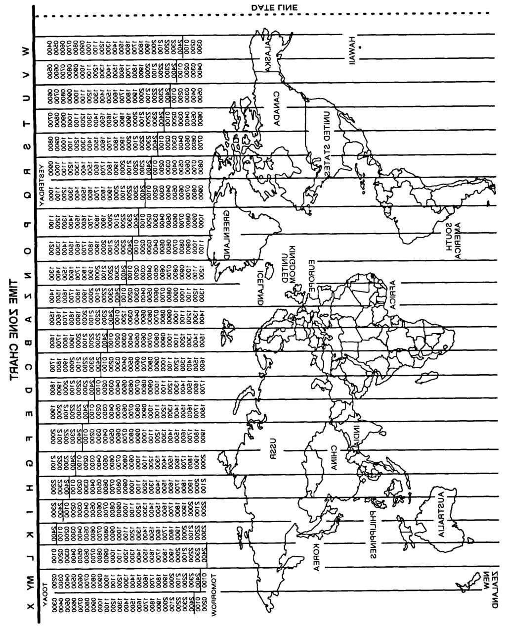
126 A-3
127 Section Ill. AIRBORNE OPERATOR ROADMAP TASKS (WHEN DESIGNATED BY COMMANDER) (UNIT SOP MAY CALL FOR LOCAL FILL TASKS TO BE PERFORMED BY COMMUNICATIONS SPECIALISTS OR KEY NCO S) A-4
128 A-5
129 A-6
130 A-7
131 TM FLOWCHART A-8
132 FLOWCHART TASK 3: NET OPENING TASK 3-1 ACTIONS RESULTS SET: (1) Follow: NCS directions RT Controls (2) Set: PRESET to MAN FCTN to LO MODE to FH A-9
133 TM FLOWCHART RECEIVE: ERF STORE: TASK 3: NET OPENING TASK 3-2 ACTIONS RESULTS (1) Wait: For NCS to send ERF ERF When ERF received Display shows "HF XXX" or "HL XXX" ICOM KEYBOARD (2) Press: Sto- Number as directed Sto X, blinks NON-ICOM KEYBOARD TASK 3-3 ACTIONS RESULTS CHECK: Communications (1) Set: FCTN to SQ ON PRESET to where ERF is stored F XXX (2) Answer: NCS call This task is completed A-10
 Seek Line-of-Sight Avoid loss of communication HILL, ETC.")
134 FLOWCHART TASK 4: COMMUNICATE IN FH NET TASK 4-1 ACTIONS RESULTS COMMUNICATE: (1) Push -to-talk Message sent With Airborne radio (2) Adjust volume to hear Message received (3) Seek Line-of-Sight Avoid loss of communication HILL, ETC. (POOR LOS) GOOD LOS (4) React if jammed Avoid IOSS of communication A-11
135 FLOWCHART TASK 4: COMMUNICATE IN FH NET TASK 4-2 ACTIONS RESULTS PROVIDE: RXMT Communication RETRANSMIT ARRANGEMENT (SC TO SC) (1) Get: RXMT frequency from SOI (2) Check: Commumcatlon, A to C and D to B A-12
136 FLOWCHART TASK 4: COMMUNICATE IN FH NET TASK 4-2 ACTIONS RESULTS (3) Set: C and D FCTN to RXMT A has SC communications with B through RXMT station (1) Get: (2) Load: RXMT FH data from SOI C and D for FH communications A and C: F1 B and D: F2 (3) Set: (4) Set: A and D (or C and B) to FH-M C and D FUNCTION to RXMT A has FH communications with B through RXMT station (1) Get: (2) Check (3) Set: RXMT SC and FH data from sol SC communications, D - B (or A to C) FH communications, A - C (or B to D) C and D FCTN to RXMT A has FH to SC communications with B through RXMT station A-13
137 FLOWCHART TASK 4: COMMUNICATE IN FH NET TASK 4-3 ACTIONS RESULTS SEND: (1) Contact: (D) ERF Ask B if ERF is needed for If yes, go to step (2) RXMT, (2) Set: (D) FCTN to LD MODE to FH-M PRESET to MAN (2) Press: (D) LOAD (H-Ld) PRESET number ERF (SEnd) ERF sending complete. A-14
138 FLOWCHART TASK 5: MAINTAIN NET TASK 5-1 ACTIONS RESULTS RECEIVE: (1) Follow: FH NET UPDATE NCS directions (2) Set: (3) Wait: FCTN to LD For NCS to send ERF HF XXX or HL XXX (4) Press: STO (Sto/ENT) Sto - Number of PRESET to store ERF Sto X, blinks (5) Turn: To PRESET where ERF is stored F XXX (6) Set: FCTN to SQ ON FH net update completed TASK 5-2 ACTIONS RESULTS LATE NET ENTRY: (1) Press: Passive method FREQ F XXX SYNC (L. E.) LF XXX Note: Press SYNC (L. E.) again to cancel late net entry mode (2) Wait: For radio traffic (DO NOT PRESS PTT SWITCH) Communications heard F XXX (L is dropped) A-15
139 FLOWCHART TASK 5: MAINTAIN NET TASK 5-2 ACTIONS RESULTS (3) Check: Communication Passive LNE is completed Note: After 3 minutes, go to CUE and ERF LNE method TASK 5-3 ACTIONS RESULTS Late Net Entry CUE and ERF method (1) Turn: KY-58 to OFF (2) Set: (3) Press: (4) Turn: PRESET to CUE FCTN to SQ OFF VOL to full IFM to HI PIT for 4 seconds KY-58 ON at once to hear response (5) Repeat after 15 seconds, if necessary (6) When CUE is answered, request CUE and ERF complete ERF A-16
140 APPENDIX B MAINTENANCE ALLOCATION CHART Section I. INTRODUCTION B-1. GENERAL. a. The Maintenance Allocation Charts (MAC) in Section II assign maintenance functions in accordance with the Three Levels of Maintenance concept for Army aviation. These maintenance levels (categories) Aviation Unit Maintenance (AVUM), Aviation Intermediate (AVIM), and Depot Maintenance are depicted on the MAC as: AVUM, which corresponds to an O Code in the Repair Parts and Special Tools List (RPSTL) AVIM, which corresponds to an F Code in the Repair Parts and Special Tools List (RPSTL) DEPOT, which corresponds to a D Code in the Repair Parts and Special Tools List (RPSTL) b. The maintenance to be performed below depot and in the field is described as follows: (1) Aviation Unit Maintenance (AVUM) activities will be staffed and equipped to perform high frequency On- Aircraft maintenance tasks required to retain or return aircraft systems to serviceable condition. The maintenance capability of the AVUM will be governed by the Maintenance Allocation Chart (MAC) and limited by the amount and complexity of ground support equipment (GSE), facilities required, authorized manning strength, and critical skills available. The range and quantity of authorized spare modules/components will be consistent with the mobility requirements dictated by the air mobility concept. (Assignments of maintenance tasks to divisional company size aviation units will consider the overall maintenance capability of the division, the requirement to conserve personnel and equipment resources, and air mobility requirements.) (a) Company Size Aviation Units: Perform those tasks which consist primarily of preventive maintenance and maintenance repair and replacement functions associated with sustaining a high level of aircraft operational readiness. Perform maintenance inspections and servicing to include preflight, daily, intermediate, periodic (or phased), and special inspections as authorized by the MAC or higher headquarters. Identify the cause of equipment/system malfunctions using applicable technical manual troubleshooting instructions, built-in test equipment (BITE), installed aircraft instruments, or test, measurement, and diagnostic equipment (TMDE). Replace worn or damaged modules/components that do not require complex adjustments or system alinement and which can be removed/installed with available skills, tools, and ground support equipment. Perform operational and continuity checks and make minor repairs to the electrical system. Inspect, service, and make operational, capacity, and pressure checks to hydraulic systems. Perform servicing, functional adjustments, and minor repair/replacement to the flight control, propulsion, power train, and fuel systems. Accomplish airframe repair that does not require extensive disassembly, jigging, or alinement. The manufacture of airframe parts will be limited to those items which can be fabricated with tools and equipment found in current air mobile tool and shop sets. Evacuate unserviceable modules/components and end items beyond the repair capability of AVUM to the supporting AVIM. (b) Less than Company Size Aviation Units: Aviation elements organic to brigade, group, battalion headquarters, and detachment size units are normally small and have less than ten aircraft assigned. Maintenance tasks performed by these units will be those which can be accomplished by the aircraft crew chief or assigned aircraft repairman and will normally be limited to preventive maintenance, inspections, servicing, spot painting, stop drilling, application of nonstress patches, minor adjustments, module/component fault diagnosis, and replacement of selected modules/components. Repair functions will normally be accomplished by the supporting AVIM unit. B 1
141 B 1. GENERAL. Continued (2) Aviation Intermediate Maintenance (AVIM) provides mobile, responsive One-Stop maintenance support. (Maintenance functions which are not conducive to sustaining air mobility will be assigned to depot maintenance). AVIM may perform all maintenance functions authorized to be done at AVUM. Repair of equipment for retum to user will emphasize support or operational readiness requirements. Authorized maintenance includes replacement and repair of modules/ components and end items which can be accomplished efficiently with available skills, tools, and equipment. AVIM establishes the Direct Exchange (DX) program for AVUM units by repairing selected items for return to stock when such repairs cannot be accomplished at the AVUM level. The AVIM level inspects, troubleshoots, performs diagnostic tests, repairs, adjusts, calibrates, and alines aircraft system modules/components. AVIM units will have capability to determine the serviceability of specified modules/components removed prior to the expiration of the Time Between Overhaul (TBO) or finite life. Module/component disassembly and repair will support the DX program and will normally be limited to tasks requiring cleaning and the fabrication of seals, fittings, and items of common manufacture. Airframe repair and fabrication of parts will be limited to those maintenance tasks which can be performed with available tools and test equipment. Unserviceable repairable modules/components and end items which are beyond the capability of AVIM to repair will be evacuated to Depot Maintenance. AVIM will perform aircraft weight and balance inspections and other special instructions which exceed AVUM capability. Provides quick response maintenance support, including aircraft recovery and air evacuation, on-the-job training, and technical assistance through the use of mobile maintenance contact teams. Maintains authorized operational readiness float aircraft. Provides collection and classification services for serviceable/unserviceable material, Operates a cannibalization activity in accordance with AR (The aircraft maintenance company within the maintenance battalion of a division will perform AVIM functions consistent with air mobility requirements and conservation of personnel and equipment resources. Additional intermediate maintenance support will be provided by the supporting nondivisional AVIM unit.) B-2. USE OF THE MAINTENANCE ALLOCATION CHART a. The Maintenance Allocation Chart assigns maintenance functions to the lowest category of maintenance based on past experience and the following considerations: (1) Skills available. (2) Work time required. (3) Tools and test equipment required and/or available. b. Only the lowest category of maintenance authorized to perform a maintenance function is indicated. If the lowest maintenance category cannot perform all tasks of any single maintenance function (e.g., test, repair), then the higher maintenance level(s) that can accomplish additional tasks will also be indicated. c. A maintenance function assigned to a maintenance category will automatically be authorized to be performed at any higher maintenance category. d. A maintenance function that cannot be performed at the assigned category of maintenance for any reason may be evacuated to the next higher maintenance category. Higher maintenance categories will perform the maintenance functions of lower maintenance categories when required or directed by the commander that has the authority to direct such tasking. e. The assignment of a maintenance function will not be construed as authorization to carry the related parts or spares in stock. Information to requisition or otherwise secure the necessary repair parts will be as specified in the associated Repair Parts and Special Tools List (RPSTL). f. Normally there will be no deviation from the assigned level of maintenance. In cases of operational necessity, maintenance functions assigned to a maintenance level may, on a one-time basis and at the request of the lower maintenance level, be specifically authorized by the maintenance officer of the level of maintenance to which the function is assigned. The special tools, equipment, etc. required by the lower level of maintenance to perform this function will be furnished by the maintenance level to which the function is assigned. This transfer of a maintenance function to a lower maintenance level does not relieve the higher maintenance level of the responsibility for the function. The higher level of maintenance will provide technical supervision and inspection of the function being performed at the lower level. g. Changes to the Maintenance Allocation Chart will be based on continuing evaluation and analysis by responsible technical personnel and on reports received from field activities. B-2
142 B-3. MAINTENANCE FUNCTIONS. a. lnspect. To determine the serviceability of an item by comparing its physical, mechanical, and/or electncal characteristics with established standards through examination (e.g., by sight, sound, or feel). b. Test. To verify serviceability by measuring the mechanical, pneumatic, hydraulic, or electrical characteristics of an item and comparing those characteristics with prescribed standards. c. Service. Operations required periodically to keep an item in proper operating condition, i.e., to clean (includes decontaminate, when required), to preserve, to drain, to paint, or to replenish fuel, lubricants, chemical fluids, or gases. d. Adjust. To maintain or regulate, within prescribed limits, by bringing into proper or exact position, or by setting the operating characteristics to specified parameters. e. Align. To adjust specified variable elements of an item to bring about optimum or desired performance. f. Calibrate. To determine and cause corrections to be made or to be adjusted on instruments or test, measuring, and diagnostic equipments used in precision measurement. Consists of comparisons of two instruments, one of which is a certified standard of known accuracy, to detect and adjust any discrepancy in the accuracy of the instrument being compared. g. Remove/Install. To remove and install the same item when required to perform service or other maintenance functions. Install may be the act of replacing, seating, or fixing into position a spare, repair part, or module (component or assembly) in a manner to allow the proper functioning of an equipment or system. h. Replace. To remove an unserviceable item and install a serviceable counterpart in its place. Replace is authorized by the MAC and is shown as the 3d position code of the SMR code. i. Repair. The application of maintenance services 1, including fault location, trouble shooting 2, removal/installation, and disassembly/assembly 3 procedures, and maintenance actions 4 to identify troubles and restore serviceability to an item by correcting specific damage, fault, malfunction, or failure in apart, subassembly, module (component or assembly), end item, or system. j. Overhaul. That maintenance effort (service/action) prescribed to restore an item to a completely serviceable/operational condition as required by maintenance standards in appropriate technical publications (i.e., DMWR). Overhaul is normally the highest degree of maintenance performed by the Army. Overhaul does not normally return an item to like new condition. k. Rebuild. Consists of those services/actions necessary for the restoration of unserviceable equipment to alike new condition in accordance with original manufacturing standards. Rebuild is the highest degree of materiel maintenance applied to Army equipment. The rebuild operation includes the act of returning to zero those age measurements (hours/ miles, etc.) considered in classifying Army equipment/components Services - inspect, test, service, adjust, aline, calibrate, and/or replace. Fault locate/troubleshoot - The process of investigating and detecting the cause of equipment malfunctioning; the act of isolating a fault within a system or unit under test (UUT). Disassemble/assemble encompasses the step-by-step taking apart (or breakdown) of a spare/ functional group coded item to the level of its least componency identified as maintenance significant (i.e., assigned an SMR code) for the category of maintenance under consideration. Actions - welding, grinding, riveting, straightening, facing, remachining and/or resurfacing. B-3
143 B-4. EXPLANATION OF COLUMNS IN THE MAC, SECTION II a. Column 1, GroupNumber. Group numbers identify maintenance significant components, assemblies, subassemblies, and modules with the next higher assembly. b. Column 2, Component/Assembly. Column 2 contains the names of components, assemblies, subassemblies, and modules for which maintenance is authorized. c. Column 3, Maintenance Functions. Column 3 lists the functions to be performed on the items listed in column 2. (For detailed explanation of these functions, see paragraph B-3). d. Column 4, Maintenance Categories and Work Times. The maintenance categories (levels) AVUM, AVIM, and DEPOT are listed on the Maintenance Allocation Chart with individual columns that include the work times for maintenance functions at each maintenance level. Work time presentations such as O. 1 indicate the average time it requires a maintenance level to perform a specified maintenance function. If a work time has not been established, the columnar presentation shall indicate -.-. Maintenance levels higher than the level of maintenance indicated are authorized to perform the indicated function. e. Column 5 and Section III. Common tool sets (not individual tools), special tools, test, and support equipment required to perform maintenance functions are listed in Section III with a reference number to permit cross-referencing to column 5 in the MAC. In addition, the maintenance category authorized to use the device is listed along with the item National Stock Number (NSN) and, if applicable, the tool number to aid in identifying the tool/device. f. Column 6 and Section IV. Remarks (identified by an alphabetic code in column 6) and other notes (identified by a number in parentheses in the applicable column) are listed in Section IV to provide a ready reference to the definition of the remark/note. B-4
144 Section Il. MAINTENANCE ALLOCATION CHART FOR AN/ARC-201(V) AND AN/ARC-201A(V) (4) (1) (2) (3) Maintenance Category (5) (6) Group Component/Assembly Maintenance Tools and Remarks Number Function AVUM AVIM DEPOT Equipment 00 Non lcom Radio Set [AN/ARC-201 (V)] Test 0.1 1,2 01 Receiver-Transmitter, Inspect 0.1 Radio RT-1476/ARC-201 (V) Inspect 0.1 (Unit 1) Test 0.1 1,2 Test Service A Install Replace Repair 0.1 1,2 B Repair 0.5 2, Panel, Receiver-Transmitter Test ,12 (1A1) Replace Repair B Repair 0.4 9,11 13 G CCA, Local Control (1A1A1) inspect 0.1 Repair , Electronic Component Assy Install ,16 (1A1A1U2) Electronic Component Assy Install ,16 (1A1A1U3) Electronic Component Assy Install ,17 (1A1A1U4) Electronic Component Assy Install ,18 (1A1A1U1) Electronic Component Assy Install ,17 (1A1A1U5) Panel, Front, Receiver- Repair 0.1 C Transmitter Repair 0.1 9, Electronic Components Inspect 0.1 Assy - Control (1A2) Test ,23 Replace 0.1 9,10 Repair 0.1 9,11,13, CCA-Microprocessor/ Repair ,15 Memory (1A2A1 ) CCA-Control I/O (1A2A2) Repair ,15 B 5
145 Section Il. MAINTENANCE ALLOCATION CHART FOR AN/ARG-201(V) AND AN/ARG-201A(V) (4) (1) (2) (3) Maintenance Category (5) (6) Group Component/Assembly Maintenance Tools and Remarks Number Function AVUM AVIM DEPOT Equipment 0103 Control, Counter-Counter- Test ,24 measures, Electronic (1A3) Replace 0.1 9,10 Repair 0.2 9,11,13, 24, Electronic Components Inspect 0.1 Assy (1A3A1) Repair 0.2 9,13, CCA-lnterleaver (1A3A1A2) Repair , CCA-Memory (1A3A1A1) Repair 0.5 9,14, CCA-interface (1A4) Inspect 0.1 Test Replace 0.1 9,10 Repair 0.5 9,14, CCA-Switching (1A5) Inspect 0.1 Test ,27,30, 31 Replace 0.1 9,10 Repair 0.5 9,14,15,26, 27,30, IF/Demodulator (1A6) Test ,27, 32,33 Replace 0.1 9,10 Repair 0.3 9,26,27, CCA-lF/Demodulator Inspect 0.1 (1A6A1) Repair Tuner/Mixer (1A7) Test ,27, 30,35 Replace 0.1 9,10 Repair 0.3 9,26,27,30 34, CCA-Tuner/Mixer (1A7A1) Inspect 0.1 Repair , Synthesizer, Electrical Test ,27,30, Frequency (1A8) Replace 0.1 9,10 Repair 0.6 9,26,27,30 35, CCA Dual Mode PLL Filter Inspect 0.1 (1A8A1) Repair , Electronic Component Assy Install ,37 (1A8A1U8) B-6
146 Section Il. MAINTENANCE ALLOCATION CHART FOR AN/ARC-201(V) AND AN/ARC-201A(V) (1) Group Number (2) Component/Assembly (3) Maintenance Function (4) Maintenance Category AVUM AVIM DEPOT (5) Tools and Equipment (6) Remark! CCA-LOW Level VCO (1A8A2) Inspect Repair , Electronic Component Assy (1A8A2U1) Install , Amplifier-Oscillator (1A9) Test Replace Repair ,27,29, 9 9, 13,26,2: 29, CCA-Modulator (1A9A1) Inspect Repair ,14, Electronic Component Assy (1A9A1U3) Install , Electronic Component Assy (1A9A1U6) Install , CCA-Filter & ALC (1A9A2) Inspect Repair ,14, Electronic Component Assy (1A9A2U6) Install , CCA-Power Amplifier (1A9A3) Inspect Repair , Power Supply (1A10) Test Replace Repair , CCA-Power Supply (1A10A1) Inspect Repair , Chassis, Electrical Equipment (1A11) Test Replace Repair ,39 1,10 9,11,14, 19, Backplane Assy Chassis (1A11A1) Inspect Repair ,14 B-7
147 Section Il. MAINTENANCE ALLOCATION CHART FOR AN/ARC-201(V) AND AN/ARC-201A(V) (1) (2) (3) (4) (5) (6) Group Component/Assembly Maintenance Maintenance Category Tool and Remarks Number Function AVUM AVIM DEPOT Equipment 00 ICOM Radio Set Test 0.1 1,49 [AN/ARC-201A(V)] 02 Receiver Inspect 0.1 Transmitter, Test 0.1 1,49 Radio Test 0.4 3,8,9,10, RT-1476A/ 49 ARC-201A(V) Service A (Unit 1) Install Replace Repair B Repair Panel, Receiver Inspect 0.1 Transmitter Test (1A1) Replace 0.2 _._ 9 Repair B Repair CCA, Local Inspect 0.1 Control Repair ,15 (1A1A1) Electronic Disassemble/ Component Assy Assemble ,16 (1A1A1U2) Electronic Disassemble/ ,16 Component Assy Assemble (1A1A1U3) Electronic Disassemble/ ,17 Component Assy Assemble (1A1A1U4) Electronic Disassemble/ ,18 Component Assy Assemble (1A1A1U1) Electronic Disassemble/ Component Assy Assemble ,17 (1A1A1U5) Panel, Front Repair 0.1 C RCVR/XMTR Repair 0.1 9,19-22 B 8
148 Section II. MAINTENANCE ALLOCATION CHART FOR AN/ARC-201(V) AND AN/ARC-201A(V) (1) (2) (3) Group Component/Assembly Maintenance Number Function (4) (5) (6) Maintenance Category Tool and Remarks AVUM AVIM DEPOT Equipment 0202 Electronic Inspect 0.1 Component Assy Test (1A2) Replace 0.1 _._ 9,10 Repair CCA, Repair 0.6 9,13,14,15 Microprocessor/ Memory (1A2A1) Electronic Disassemble/ ,18 Component Assy Assemble (1A2A1U1) CCA, Control Repair 0.5 9,13,14,15 I/O (1A2A2) Electronic Disassemble/ ,16 Component Assy Assemble (1A2A2U5) Electronic Disassemble/ ,16 Component Assy Assemble (1A2A2U6) 0203 Control, ECCM, Inspect 0.1 Electronic Test (1A3) Replace 0.1 _._ 9,10 Repair 0.2 9, Electronic Inspect 0.1 Component Assy Repair 0.2 (1A3A1) 9,13, CCA, Memory Repair 0.5 9,13,14,15 (1A3A1A1) Electronic Disassemble/ ,16 Component Assy Assemble (1A3A1A1U2) CCA, Interleave Repair 0.5 9,13,14,15 (1A3A1A2) B-9
149 Section II MAINTENANCE ALLOCATION CHART FOR AN/ARC-201(V) AND AN/ARC-201A(V) (1) Group Number (2) Component/Assembly (3) Maintenance Function (4) Maintenance Category AVUM AVIM DEPOT (5) Tools and Equipment (6) Remarks EIectronic ComponentAssy (1A3A1A2U2) Disassemble/ Assemble , EIectronic Component Assy (1A3A1A2U9) Disassemble/ Assemble , Electronic Component Assy 1A3A1A2U8) Disassemble/ Assemble , Electronic Component Assy (1A3A1A2U4) Disassemble/ Assemble , Electronic Component Assy (1A3A1A2U3) Disassemble/ Assemble , Electronic Component Assy (1A3A1A2U1) Disassemble/ Assemble , CCA, interface (1A4) Inspect Test Replace Repair ,4,5,37 9,10 9,14, 3,4,5, CCA, Switching (1A5) Inspect Test Replace Repair _. _ 9,10 9,13,14, Electronic Component Assy (1A5U2) Disassemble/ Assemble , Electronic Component Assy (1A5U3) Disassemble Assemble ,17 B-10
150 Section II. MAINTENANCE ALLOCATION CHART FOR AN/ARC-201(V) AND AN/ARC-201A(V) (1) Group Number (2) Component/Assembly (3) Maintenance Function (4) Maintenance Category AVUM AVIM DEPOT (5) Tools and Equipment (6) Remark: Electronic Component Assy (1A5U4) Disassemble, Assemble , Electronic Component Assy (1A5U5) Disassemble, Assemble , IF/Demodulator (1A6) Test Replace Repair 0.1 _._ 0.3 9,10 9,13, CCA, IF/ Demodulator (1A6A1) Inspect Repair ,13, Tuner/Mixer Assy (1A7) Test Replace Repair ,30, 35,37 9,10 3,9,30, 34,35, CCA, Tuner/ Mixer (1A7A1) Inspect Repair , Electronic Component Assy (1A7A1U2) Disassemble/ Assemble , Synthesizer, Elec Freq (1A8) Test Replace Repair ,30, 35,37 9,10 3,9,30, 35,36, CCA, Dual Mode PLL Filter (1A8A1) Inspect Repair , Electronic Component Assy (1A8A1U8) Disassemble/ Assemble , CCA, Low Level VCO (1A8A2) Inspect Repair ,15 B-11
151 Section Il. MAINTENANCE ALLOCATION CHART FOR AN/ARC-201(V) AND AN/ARC-201A(V) (1) (2) (3) Group Component/Assembly Maintenance Number Function (4) (5) (6) Maintenance Category Tools and Remarks AVUM AVIM DEPOT Equipment Electronic Disassemble/ ,17 Component Assy Assemble (1A8A2U1) 0209 Amplifier, Test 0.1 3,35, Oscillator (1A9) 37,38 Replace Repair 0.4 3,5,9,13, 37, CCA, Modulator Inspect 0.1 (1A9A1) Repair 0.6 9,14, Electronic Disassemble/ ,37 Component Assy (1A9A1U3) Assemble Electronic Disassemble/ ,17 Component Assy Assemble (1A9A1U6) CCA, Filter& Inspect 0.1 ALC (1A9A2) Repair 0.6 9,14, Electronic Disassemble/ ,37 Component Assy Assemble (1A9A2U6) CCA, Power Amp Inspect 0.1 (1A9A3) Repair 0.6 9, Power Supply Test 0.1 3,4,5,37 Assy (1A10) Replace Repair 0.4 3,4,5,9, CCA, Power Inspect 0.1 Supply (1A10A1) Repair 0.5 9, Chassis, Elec Test ,39 Equipment Replace 0.3 9,10 (1A11) Repair 0.6 9,11,14, 25, I CCA, Chassis Inspect 0.1 (1A11A1) Repair 0.5 9,13 B-12
152 Section Il. MAINTENANCE ALLOCATION CHART FOR AN/ARC-201(V) AND AN/ARC-201A(V) (1) Group Number (2) Component/Assembly (3) Maintenance Function (4) Maintenance Category AVUM AVIM DEPOT (5) Toolsand Equipment (6) Remarks 03 Receiver Transmitter, Radio RT 1477/ARC 201(V) (Unit 2) Inspect Inspect Test Test Service Install Replace Repair Repair , , A B 0301 Panel, Receiver-Transmitter (2A1) Test Replace Repair Repair , ,11,12 B G CCA Dedicated Remote (2A1A1) Inspect Repair , Electronic Component Assy (2A1A1U11) Install , Panel, Front, Receiver- Transmitter Repair 0.1 9,19-22, Electronic Components Assy- Control (2A2) D CCA Microprocessor/ Memory (2A2A1) D CCA-Control I/O (2A2A2) D 0303 Control, Counter-Countermeasures, Electronic (2A3) D Electronic Component Assy (2A3A1) D CCA lnterleaver (2A3A1A2) D CCA-Memory (2A3A1A1) D 0304 CCA-Interface (2A4) D 0305 CCA-Switching (2A5) D 0306 IF/Demodulator (2A6) D CCA-lF/Demodulator (2A6A1) D B-13
153 Section Il. MAINTENANCE ALLOCATION CHART FOR AN/ARC-201(V) AND AN/ARC-201A(V) (1) (2) (3) (4) (5) (6) Group Component/Assembly Maintenance Maintenance Category Tools and Remarks Number Function AVUM AVIM DEPOT Equipment 0307 Tuner/Mixer (2A7) D CCA-Tuner/Mixer (2A7A1) D 0308 Synthesizer, Electrical Frequency (2A8) CCA - Dual Mode PLL Filter (2A8A1) Electronic Component Assy (2A8A1U8) CCA-Low Level VCO (2A8A2) Electronic Component Assy (2A8A2U1) D D D D D 0309 Amplifier-Oscillator (2A9) D CCA-Modulator (2A9A1) D Electronic Component Assy (2A9A1U3) Electronic Component Assy (2A9A1U6) D D CCA-Filter & ALC (2A9A2) D Electronic Component Assy (2A9A2U6) CCA-Power Amplifier (2A9A3) D D 0310 Power Supply (2A10) D CCA-Power Supply (2A10A1) D 0311 Chassis, Electrical Equipment (2A11) D Backplane Assy Chassis D (2A11A1) B 14
154 Section Il. MAINTENANCE ALLOCATION CHART FOR AN/ARC-201(V) AND AN/ARC-201A(V) (1) (2) (3) Group Component/Assembly Maintenance Number Function (4) (5) (6) Maintenance Category Tools and Remarks AVUM AVIM DEPOT Equipment 04 Receiver Inspect 0.1 Transmitter, Test 0.1 1,49 Radio Test , RT 1477A/ 49 ARC-201A(V) Service A (Unit 2) Install 0.1 Replace 0.1 Repair B Repair Panel, Receiver Inspect 0.1 Transmitter Test ,24 (2A1) Replace Repair B Repair 0.4 9,11, CCA, Dedicated Inspect 0.1 Remote (2A1A1) Repair , Electronic Disassemble/ ,16 Component Assy Assemble (2A1A1U11) Panel, Front, Repair 0.1 9,19-22, RCVR/XMTR 40, Electronic D Component Assy (2A2) 0403 Control, CCM, D Electronic (2A3) 0404 CCA, Interface (2A4) 0405 CCA, Switching (2A5) 0406 IF/Demodulator (2A6) 0407 Tuner/Mixer (2A7) D D D D B-15
155 Section Il. MAINTENANCE ALLOCATION CHART FOR AN/ARC-201(V) AND AN/ARC-201A(V) (1) Group Number (2) Component/Assembly (3) Maintenance Function (4) Maintenance Category AVUM AVIM DEPOT (5) Tools and Equipment (6) Remarks 0408 Synthesizer, EIec Freq (2A8) 0409 Amplifier, Oscillator (2A9) 0410 Power Supply Assy (2A10) 0411 Chassis, Elec Equipment (2A11) 05 Receiver-Transmitter, Radio RT 1478/ARC-201(V) (Unit 3) Inspect Inspect Test Test Service Install Replace Repair Repair , , Panel, Receiver-Transmitter (3A1) Test Replace Repair ,44 9 9,11,13, CCA-Remote Terminal (3A1A1) Inspect Repair , CCA-Microformatter (3A1A2) Inspect Repair ,14, Electronic Component Assy (3A1A2U7) Install , Electronic Component Assy (3A1A2U9) Install , Electronic Component Assy (3A1A2U8) Install , Electronic Component Assy (3A1A2U10) Install , Electronic Component Assy (3A1A2U11) ,16 B-16
156 Section Il. MAINTENANCE ALLOCATION CHART FOR AN/ARC-201(V) AND AN/ARC-201A(V) (1) Group Number (2) Component/Assembly (3) Maintenance Function (4) Maintenance Category AVUM AVIM DEPOT (5) Tools and Equipment (6) Remarks CCA-Power Supply (3A1A3) Inspect Repair , Panel, Front, Receiver- Transmitter Repair 0.1 9,19-22, 40, Electronic Component Assy Control (3A2) D CCA Microprocessor/Memory (3A2A1) D CCA-Control I/O (3A2A2) D 0503 Control, Counter-Countermeasures, Electronic (3A3) D Electronic Component Assy (3A3A1) D CCA-lnterleaver (3A3A1A2) D CCA-Memory (3A3A1A1) D 0504 CCA-Interface (3A4) D 0505 CCA-Switching (3A5) D 0506 IF/Demodulator (3A6) D CCA-lF/Demodulator (3A6A1) D 0507 Tuner/Mixer (3A7) D CCA-Tuner/Mixer (3A7A1) D B-17
157 Section Il. MAINTENANCE ALLOCATION CHART FOR AN/ARC-201(V) AND AN/ARC-201A(V) (1) (2) (3) (4) (5) (6) Group Component/Assembly Maintenance Maintenance Category Tools and Remarks Number Function AVUM AVIM DEPOT Equipment 0508 Synthesizer, Electrical D Frequency (3A8) CCA Dual Mode PLL Filter D (3A8A1) Electronic Component Assy D (3A8A1U8) CCA-Low Level VCO (3A8A2) D Electronic Component Assy D (3A8A2U1) 0509 Amplifier-Oscillator (3A9) D CCA-Modulator (3A9A1) D Electronic Component Assy D (3A9A1U3) Electronic Component Assy D (3A9A1U6) CCA-Filter & ALC (3A9A2) D Electronic Component Assy (3A9A2U6) CCA Power Amplifier (3A9A3) 0510 Power Supply (3A10) CCA-Power Supply (3A10A1) 0511 Chassis, Electrical Equipment (3A11) Backplane Assy Chassis (3A11A1) D D D D D D D I B-18
158 Section Il. MAINTENANCE ALLOCATION CHART FOR AN/ARC-201(V) AND AN/ARC-201A(V) (1) (2) (3) Group Component/Assembly Maintenance Number Function (4) (5) (6) Maintenance Category Tools and Remarks AVUM AVIM DEPOT Equipment 06 Receiver Inspect 0.1 Transmitter, Test 0.1 1,49 Radio RT 1478A/ Test , ARC-201A(V) 49 (Unit 3) Service A Install 0.1 Replace 0.1 Repair 0.1 1,49 B Repair Panel, Receiver Inspect 0.1 Transmitter Test (3A1) Replace Repair Repair 0.4 9,11,24 B CCA, Remote Inspect 0.1 Terminal (3A1A1) Repair 0.6 9,11, CCA, Inspect 0.1 Microformatter Repair 0.5 (3A1A2) 9,11, Electronic Disassemble/ Component Assy Assemble ,18 (3A1A2U7) Electronic Disassemble/ ,17 Component Assy Assemble (3A1A2U9) Electronic Disassemble/ ,17 Component Assy Assemble (3A1A2U8) Electronic Disassemble/ ,16 Component Assy Assemble (3A1A2U10) Electronic Disassemble/ ,16 Component Assy Assemble (3A1A2U11) CCA, Power Inspect 0.1 supply (3A1A3) Repair 0.6 9, Panel Front, Repair 0.1 9,19-22, RCVR-XMTR 40,43 B-19
159 Section Il. MAINTENANCE ALLOCATION CHART FOR AN/ARC-201(V) AND AN/ARC-201A(V) (4) (1) (2) (3) (5) (6) Maintenance Category Group Component/Assembly Maintenance Tools and Remarks Number Function AVUM AVIM DEPOT Equipment 0602 Electronic D Component Assy (3A2) 0603 Control, CCM Electronic (3A3) 0604 CCA, Interface (3A4) 0605 CCA, Switching (3A5) 0606 IF/Demodulator D (3A6) 0607 Tuner/Mixer D (3A7) 0608 Synthesizer, D Elec Freq (3A8) 0609 Amplifier- D Oscillator (3A9) 0610 Power Supply D Assy (3A10) 0611 Chassis, Elec Equipment (3A11) D D D D 07 Control, Radio Set Inspect 0.1 C-11466/ARC-201(V) Inspect 0.1 (Unit 4) Test 0.1 1,2 Test 0.1 3,4,7,9,10 Install Replace Repair 0.1 1,2 B Repair 0.2 3,4,7,9, CCA-Processor (4A3) Inspect 0.1 Test ,23 Replace Repair 0.5 9,11,14, 15,23 B-20
160 Section Il. MAINTENANCE ALLOCATION CHART FOR AN/ARC-201(V) AND AN/ARC-201A(V) (1) (2) (3) (4) (5) (6) Group Component/Assembly Maintenance Maintenance Category Tools and Remarks Number Function AVUM AVIM DEPOT Equipment Electronic Component Assy Install (4A3U3) , Electronic Component Assy Install (4A3U6) Electronic Component Assy Install (4A3U5) Electronic Component Assy Install (4A3U4) , , , Panel, Control (4A1) Inspect 0.1 Repair B Repair 0.1 9,13 C 08 Control,Radio Inspect 0.1 Set C-11466A/ Inspect 0.1 ARC-201A(V) Test 0.1 (Unit 4) Test 0.1 3,9,10,47 Install Replace Repair B Repair CCA, Processor Inspect 0.1 (4A3) Test ,23 Replace Repair 0.5 9,11,14, 15, Electronic Disassemble/ Component Assy Assemble ,18 (4A3U3) Electronic Disassemble/ ,17 Component Assy Assemble (4A3U6) Electronic Disassemble/ Component Assy Assemble ,17 (4A3U5) Electronic Disassemble/ Component Assy Assemble ,16 (4A3U4) 0806 Panel, Control Repair 0.1 B (4A1) Repair C B-21
161 Section Il. MAINTENANCE ALLOCATION CHART FOR AN/ARC-201(V) AND AN/ARC-201A(V) (1) (2) (3) (4) (5) (6) Group Component/Assembly Maintenance Maintenance Category Tools and Remarks Number Function AVUM AVIM DEPOT Equipment 09 Mounting Base, Elec Eqpt Inspect 0.1 MT-6373/ARC-201(V) Test 0.1 1,2 (Unit 6) Test 0.1 3,10 Install Replace Repair 0.1 3,9, Tray, Mounting Base Repair B 0904 Wire Harness, Branched Repair (6W1) 10 Mounting Base, Elec Eqpt Inspect 0.1 MT-6374/ARC-201(V) Install Replace Repair B 11 Adapter, Data Rate Inspect 0.1 CV-3885/ARC-201(V) Inspect 0.1 (Unit 5) Test 0.1 1,2 Test 0.1 3,4,7,9,10 Install Replace Repair 0.1 3,4,7,9, CCA-FSK Detector (5A1) Inspect 0.1 Test ,23 Replace Repair 0.5 9,11,14, CCA-Data Processor (5A2) Inspect 0.1 Test ,27 29,45 Replace Repair 0.6 9,14,15,26, 27,29, Electronic Component Assy Install ,17 (5A3U1) Electronic Component Assy Install (5A3U2) , CCA-Power Supply (5A4) Inspect 0.1 Test ,27, 29,45 Replace Repair 0.6 9,14,26,27, 29,45 B-22
162 Section Il. MAINTENANCE ALLOCATION CHART FOR AN/ARC-201(V) AND AN/ARC-201A(V) (1) (2) (3) (4) (5) (6) Group Component/Assembly Maintenance Maintenance Category Tools and Remarks Number Function AVUM AVIM DEPOT Equipment 1108 Housing Assy, Connector Test ,46 (5A8) Replace Repair 0.1 9,11, CCA lntermediate Connector Inspect 0.1 (5A8A1) Repair 0.3 9,14 12 Fill Device, Electronic Inspect 0.1 Counter-Countermeasures Test 0.1 MX-10579/VRC (Unit 8) Test 0.1 3,48,49 Service 1 A 0.1 Repair 1 B 0.1 Repair 0.3 3,9,14, 48, CCA-Fill Device (8A1) Test ,24 Replace 0.1 9,14,49 Repair 0.6 9,11,14, 24,49 13 Fill Device, Inspect 0.1 Elec CCM Test 0.1 MX-18290/VRC Test. (Unit 8) Service A Repair B Repair CCA, Fill Device Test. (8A1) Replace 0.1 3,14 Repair 0.2 3,14 14 Battery Box Replace CY-8515 (Unit 9) 15 Maintenance Inspect 0.1 Group Test 0.8 3,15,16, OA-9264A/ARC 17,18,20 L (Unit 10) Repair 0. 9, Interconnecting Repair Device (10A1) B-23
163 Section Il. MAINTENANCE ALLOCATION CHART FOR AN/ARC-201(V) AND AN/ARC-201A(V) (1) (2) (3) (4) (5) (6) Maintenance Category Group Component/Assembly Maintenance Tools and Remarks Number Function AVUM AVIM DEPOT Equipment Receiver Service A Transmitter, Replace E Radio RT 1476A/ ARC-201A(V) Intercom Replace J C-6533/ARC Control, Radio Replace F Set C 11466A/ ARC-201A(V) Adapter, Test Repair (10A1A1) Panel, Front Repair Adapter, Data Replace Rate CV-3885/ ARC-201(V) 1502 ECCM Fill Device Replace 0.1 H MX-18290/VRC 1503 Panel, RT Replace 0.1 I 1504 Cable Assy, Repair Special Purpose, Electrical (10W1) 1505 Cable Assy, Repair Special Purpose, Electrical (10W2) 1506 Cable Assy, Repair Special Purpose, Electrical (10W3) 1510 Cable Assy, Repair Power, Elec (10W7) 1511 Cable Assy, Repair Power, Elec (10W8) B-24
164 Section II. MAINTENANCE ALLOCATION CHART FOR AN/ARC-201(V) AND AN/ARC-201 A(V) (1) Group Number (2) Component/Assembly (3) Maintenance Function (4) Maintenance Category AVUM AVIM DEPOT (5) Tools and Equipment (6) Remarks 1512 Cable Assy, Special Purpose, Electrical (10W17) Repair Cable Assy, Special Purpose, Electrical (10W10) Replace Repair Parts Kit, Elec Eqpt Repair Cable Assy, Special Purpose, Electrical (10W12) Repair B-25
165 Section Ill. TOOL AND TEST EQUIPMENT REQUIREMENTS FOR AN/ARC-201(V) AND AN/ARC-201A(V) Tool or Test Maintenance National/NATO Tool Equipment Category Nomenclature Stock Number Number Ref. Code 1 AVUM Tool Kit, Electronic Equipment TK 101/G AVUM, AVIM Fill Device, Electronic Counter MX-10579/VRC Countermeasures 3 AVIM Multimeter AN/USM AVIM Oscilloscope AN/USM AVIM Signal Generator SG-1112(V)1/U AVIM Function Generator SG-1171/U AVIM Power Supply PP 1104C/G AVIM Frequency Counter TD 1225A(V)2/U AVIM, DEPOT Tool Kit, Electronic Equipment TK-105/G AVIM Maintenance Group OA-9264A/ARC DEPOT Test Set, Digital AN/USM-465A DEPOT 465A ICD Card A (ARC-201) TBD TBD AVIM, DEPOT Tool Kit, Electronic Equipment TK 100/G DEPOT Repair CNTR, Solder PRC DEPOT SMD Solder Station Dragon M111 TBD DEPOT Soldering Fixture F TBD DEPOT Soldering Fixture F TBD DEPOT Soldering Fixture F TBD DEPOT Inserter, Screw Thr A DEPOT Extractor, Screw Thr A DEPOT Tang Breakoff Tool A DEPOT Tap, Thread Cutting A TBD DEPOT 465A ICD Card B A TBD DEPOT 465A ICD Card A A TBD DEPOT Alignment Tool, Circuit Card A TBD Assy B 26
166 Section Ill. TOOL AND TEST EQUIPMENT REQUIREMENTS FOR AN/ARC-201(V) AND AN/ARC-201A(V) Tool or Test Equipment Ref. Code Maintenance Category Nomenclature National/NATO Stock Number Tool Number 26 DEPOT Test Stat Elec Eqpt AN/USM DEPOT Interconnect Device ICD-005 TBD DEPOT Adapter Card A (ARC-201) TBD TBD DEPOT Load Card A (ARC-201) TBD TBD DEPOT Load Card A A TBD DEPOT Adapter Card B A TBD DEPOT Adapter Card C A TBD DEPOT Load Card B A TBD DEPOT Alignment Tool, Circuit Card Assy A TBD DEPOT Adapter Card A A TBD DEPOT Alignment Tool, Circuit Card Assy A TBD DEPOT Soldering Fixture F TBD DEPOT Adapter Card C (ARC-201) TBD TBD DEPOT ICD Cable Assy C (ARC-201) TBD TBD DEPOT Inserter, Screw Thr A TBD DEPOT Extractor, Screw Thr A DEPOT Tang Breakoff Tool A DEPOT Tap, Thread Cutting A TBD DEPOT ICD Cable Assy F (ARC 201) TBD TBD DEPOT Adapter Card B (ARC-201) TBD TBD DEPOT ICD Cable Assy D (ARC-201) TBD TBD DEPOT Alignment Tool, Backplane TBD TBD DEPOT Tape Reader KOI TBD 49 AVUM/AVIM Fill device, Electric Counter Countermeasures MX 18290/VRC DEPOT Wrench, Torque B25 Right B 27
167 Section IV. AN/ARC-201(V) AND AN/ARC-201A(V) REMARKS Reference Code Remarks/Notes A B By replacement of hold up battery. By replacement of piece parts (knobs, holddown hooks, etc.). C Dzus fasteners are to be replaced at AVIM metal shop (ref. TM ) D E F G H Identical component, reference group number 01XX. Identical component, reference group number 01 for Non-lCOM and 02 for ICOM. Identical component, reference group number 07 for Non lcom and 08 for ICOM. 1A1 and 2A1 modules in Korea will be repaired by the Special Repair Activity (SRA) at Camp Carroll, Korea. Identical component, reference group number 12 for Non lcom and 13 for ICOM. I Identical component, reference group number J For repair of the Intercom (C-6533/ARC), see TM , TM P, TM , and TM P. K L Repair by replacement of items in kit. For power, Power Supply HP6434B, NSN: , or its equivalent may be used. B-28
168 APPENDIX D ADDITIONAL AUTHORIZATION LIST Section I. INTRODUCTION D-1. SCOPE. This appendix lists additional items you are authorized for the support of the radio set. D-2. GENERAL. The list identifies items that do not have to accompany the radio set and that do not have to be turned in with it. These items are authorized to you by CTA, MTOE, TDA, or JTA. D-3. EXPLANATION OF LISTING. National stock numbers, descriptions, and quantities are provided to help you identify and request the additional items you require to support this equipment. The items are listed in alphabetical sequence by item name. Section Il. ADDITIONAL AUTHORIZATION LIST (1) (2) (3) (4) National Stock Description U/M Qty Number (CAGEC) and Part Number Auth Non-lCOM [AN/ARC-201(V)] RADIO SETS BATTERY, NON-RECHARGEABLE ea 1/RT, (80058) BA-5372/U (hold up battery) 1/fill device BATTERY, NON-RECHARGEABLE ea 5/bat- (81349) BA-3042/U (C-cell) tery box CABLE, FILL (ECCM fill cable) ea 1 (98230) 0N FILL DEVICE, ELECTRONIC ea 1 COUNTER COUNTERMEASURES MX-10579/VRC (80063) A OR FILL DEVICE, ELECTRONIC ea 1 COUNTER COUNTERMEASURES MX-18290/VRC (80063) A READER, TAPE, GENERAL PURPOSE ea 1 (98230) KOI-18/TSEC D-1
 (2) (3) (4) National Stock Description U/M Qty Number (CAGEC) and Part Number Auth ICOM [AN/ARC-201A(V)] RADIO SETS 6135-01-214-6441 BATTERY, NON-RECHARGEABLE ea")
169 Section Il. ADDITIONAL AUTHORIZATION LiST (1) (2) (3) (4) National Stock Description U/M Qty Number (CAGEC) and Part Number Auth ICOM [AN/ARC-201A(V)] RADIO SETS BATTERY, NON-RECHARGEABLE ea 1/RT, (80058) BA-5372/U (hold up battery) 1/fill device BATTERY, NON-RECHARGEABLE ea 5/bat- (81349) BA-3042/U (C-cell) tery box CABLE, FILL (ECCM fill cable) ea 1 (98230) 0N DEVICE, ELECTRONIC TRANSFER ea 1 (98230) KYK-13/TSEC FILL DEVICE, ELECTRONIC COUNTER ea 1 COUNTERMEASURES MX-18290/VRC (80063) A READER, TAPE, GENERAL PURPOSE ea 1 (98230) KOI-18/TSEC D-2
170 APPENDIX E REFERENCE DATA PAGE SECTION I. Glossary E-1 Il. Abbreviations E-2 Ill. Nomenclature Cross-Reference List E-3 Section I. GLOSSARY Term cold start net opening cold start TSK ECCM Electronic remote fill (ERF) FH sync time frequency hopping (FH) hopset jamming loading Iocal fill lockout set NCS radio net member net ID offset preset preset frequency sidetone single channel (SC) Definition A net opening procedure which ensures net radios have the same FH data (TRANSEC, Iockout set, hopset, net ld, and sync time) as the NCS radio. Transmission security key (TSK) which, when combined with proper switch settings will result in Cold display. It can only be loaded by local fill. A method of operation to counter enemy jamming and direction finding measures. A method whereby an RT is loaded with selected FH data by radio transmission from an NCS RT. Electronic control data required for FH operation. The radios in a FH net must have the same FH sync time to synchronize their frequency hopping. An ECCM mode of operation; RT automatically changes operating frequency 100 times per second. Data in the RT that determines which frequencies will be used by the RT during FH. It is used by all radios in a net. Signals intentionally transmitted to interfere with the transmission or reception of another station. Putting electronic control information into the memories of the RT. Refers to loading of COMSEC keys into KY-58 using KYK-13 and FH data into RT using ECCM fill device. Data which prevents transmission/reception on particular frequencies. Normally, lockout sets will not be required, The radio used by the net control station which automatically maintains net sync time; operates in the FH-M mode. Any radio in a SINCGARS net, other than the NCS. A three digit identification; provides starting point for frequency hopping. To change a single channel operating frequency by adding or subtracting 5 or 10 khz. Offsetting is done to reduce the effects of jamming or interference. A memory location in an RT in which frequencies or hopsets can be loaded in or stored. The SC frequency loaded into a preset. Audio you hear in your headset when you key the transmitter and talk into your microphone. A mode of operation in which a radio operates on one selected frequency. E-1
171 GLOSSARY Continued Term squelch TRANSEC key zero all Definition An RT feature that eliminates the rushing noise in your headset when no real signal is being received. Electronic control data required in RT for FH operation. Establishes the hopping sequence. An operating procedure that clears all SC frequencies, FH data, and sync time from RT memory. Zero all also clears the TRANSEC key and net sync time. Section Il. ABBREVIATIONS Abbreviation ANVIS AVIM AVUM BITE COMSEC CT DMWR DRA DX ECCM ERF FH FM FSK GSE HM HOM HUB ICOM ID IFM KEK LCD LNE LOS MAC MAN NCS NOE NON-ICOM NSN Term aviator night vision imaging system aviation intermediate maintenance aviation unit maintenance built-in test equipment communications security cypher text depot maintenance work requirements data rate adapter direct exchange electronic electronic remote fill frequency hopping frequency modulation frequency shift keying counter-countermeasures ground support equipment holding memory homing hold up battery integrated COMSEC identification improved frequency modulation key encryption key liquid crystal display late net entry line of sight maintenance allocation chart manual net control station nap of earth non-integrated COMSEC national stock number E-2
172 ABBREVIATIONS Continued PM PMCS PPM PT PTT RF RPSTL RT RCU RXMT SC SINCGARS SMR SOI SOP SQ TBO TEK TMDE TSK TRANSEC UUT Common Name permanent memory preventive maintenance checks and services parts per million plain text push-to-talk radio frequency repair parts and special tools list receiver-transmitter remote control unit retransmit single channel single channel ground and airborne radio system source, maintenance, and recoverability (codes) signal operation instructions (formerly CEOI) standard operating procedure squelch time between overhaul traffic encryption key test, measurement, and diagnostic equipment transmission security key transmission security unit under test Section III. NOMENCLATURE CROSS-REFERENCE LIST Official Nomenclature holding battery battery box DRA ECCM fill device IFM power amplifier mounting base radio set, Non-lCOM RCU RT Battery, Non-rechargeable BA-5372/U Battery Box CY-8515/ARC-201(V) Adapter, Data Rate CV-3885/ARC-201(V) Fill Device MX-10579/VRC or MX-18290/VRC Power Amplifier AM-7189A/VRC Mounting Base, Electrical Equipment MT-6373/ARC-201(V), MT-6374/ARC-201(V), MT-6709/ARC-201A(V), MT-6710/ARC-201A(V) AN/ARC-201(V) Control, Radio Set C-11466/ARC-201(V) or C-11466A/ARC-201A(V) Receiver-Transmitter, Radio RT-1476/ARC-201(V), RT-1477/ARC-201(V), RT-1478/ARC-201(V), RT-1476A/ARC-201A(V), RT-1477A/ARC-201A(V), RT-1478A/ARC-201A(V) E-3/(E-4 blank)
173
174 ALPHABETICAL INDEX Subject, Para Subject, Para A Audio Signals, 1-16 Administrative Storage, 6-36 Anti-Jamming, 3-10 B Battery Box, 1-9 Bringing Another Station into Net, 3-8 C Capabilities, 1-8 Changing a Net ID, 2-22 Cleaning, 5-2, 6-9 Clearing a Frequency, 1-12, 2-15 Clearing a Single FH Set, 3-9 Clearing an Offset Frequency, 2-17 Clearing Data from Fill Device, 2-18 Clearing FH Sync Time, 3-4 Cold Start Net Opening, 2-24, 3-6 Cold Weather, 4-7 Components, 1-9 Controls, Fill Device, 2-11 Controls, RCU, 2-10 Controls, RT, 2-10 COMSEC Operation, 1-16, 1-18 Connectors, Fill Device, 2-11 Connectors, RCU, 2-10 Connectors, RT, 2-10 Cue, 1-13, 1-17, 2-14, 2-15, 2-26, 3-6, 3-8 Cue and ERF, 2-27, 3-8 D Data Rate Adapter, 1-20 Data Rate Adapter Checks, 2-7, 6-13 Data Operation, 1-20 Data, Equipment, 1-11 Destruction to Prevent Enemy Use, 1-7 Differences between Models, 1-10 Dimensions, 1-11 Display, 1-12, 2-10 E ECCM Fill Device, 1-9, 2-11, 2-18 ECCM Fill Device Check, 2-9, 2-18 Electronic Remote Fill (ERF), 1-14, 1-19, 2-24, 2-25, 2-27, 3-6, 3-7, 4-3 Entering Another Net, 2-27 Equipment Data, Equipment Improvement Recommendations (EIR), 1-4 F Features, 1-8 FH Data Loading, 1-14, 1-19, 2-24, 2-25 FH Sync Time, 1-14, 1-15, 1-17, 3-6 Fill Connector, 2-11 Fill Data Check, 2-18 Fill Device, 1-9, 2-11 Fill Holding Test, 6-13 Flowcharts, 6-16, 6-31, Appendix A Forms, Records, and Reports, 1-2 Frequency Hopping, 1-14, 1-17 Frequency Hopping-Master, 1-17 FUNCTION Switch, 2-10 Homing, 1-23, 4-6 Hopset, 1-14, 1-17, 3-6 H I IFM RF PWR Switch, 2-10 IFM Power Amplifier Self-Test, 2-8 Inspection, 6-18 Installation, 6-6 Intermediate Storage, 6-37 J Jamming, 3-10, 4-10 Julian Date, 3-4, Appendix K Keyboard Local Fill, 1-19, 2-20, 2-21, 2-22 Keyboard, 1-9, 1-12, 2-13 KY-58, 1-8, 1-9, 1-18, 1-20 KYK-13, 2-11, Appendix A, Appendix E L Late Net Entry, 2-27 Line of Sight, 4-9 Loading FH Sync Time, 3-4 A INDEX-1
175 ALPHABETICAL INDEX Continued. Subject, Para Subject, Para Loading a Frequency, 2-14 Loading FH data, 1-19, 2-20, 2-21 Loading a TRANSEC Key, 2-19 Loading an Offset, 2-16 Loading RT from Fill Device, 2-18 Loading Fill Device from Another Fill Device, 3-3 Local Fill, 1-19 Lockout Set, 1-14, 1-17, 3-6 M Maintenance, 6-17 Maintenance Allocation Chart, Appendix B Maintenance, Fill Device, 6-28 through 6-33 MAN, 1-13, 2-14, 2-15, 3-6 MODE Switch, 2-10 Mounting Base, 1-9 N Nap of Earth, 4-9 Net Control Station (NCS), 3-2 Net ID, 1-14, 2-22 Net Opening, 2-23, 3-5 Net Update, 2-25, 3-7 Nomenclature, 1-9 Nuclear Radiation, 4-9 O Offset, 1-12, 2-16, 2-17 Operation with Data Equipment, 4-4 Operational Check, 6-13 Operational Check List, 6-13 Operator Tasks, 2-12 through 2-27, Appendix A P Painting, 6-11 Parts, Appendix B PMCS, 5-5, 6-8, 6-29 Power Input, 1-22 Pre-Mission Check, 2-12 PRESET Switch, 2-10 Publications, 1-3, Appendix A Preventive Maintenance Checks and Services (PMCS), 5-1, 5-5, 6-8, 6-29 Receiver-Transmitter, 1-9 Repair, 6-1, 6-4, 6-20 through 6-26 Reporting Errors, 1-5 Retransmit Operation, 1-24, 4-2, 4-3 Roadmap, Appendix A RT Load Checks, 2-6 RT Self-Test, 2-3, 6-13 RT Transmit Check, 2-5 RT Z-A Check, 2-4 S Safety, 5-3, 6-10 Scanning, 4-5 Security Classification and Marking, 1-6 Self-Test, 2-2 through 2-9 Shipment, 6-34 Single Channel, 1-13, 2-14 Special Instructions, 5-4 Special Tools, 6-3 Storage, 6-34 Sync Time, 1-14, 1-15, 1-17, 3-6 T Tasks, Appendix A Test, Measurement, and Diagnostic Equipment (TMDE), 6-3 Time, FH Sync, 1-14, 1-15, 1-17, 3-6 Time Zones, Appendix A TOOlS, 6-2 Touch-up Painting, 6-11 TRANSEC Key, 1-14, 1-17, 3-6 Transmission Security Key, 1-14, 1-17, 3-6 Troubleshooting, 3-11, 4-11, 6-16 Unpacking, 6-5 Verification of Repair, 6-19 VOL Control, 2-10 VSWR, 2-5 U V R Remote Control, Radio Set, 1-9, 1-21 Weights, 1-11 W INDEX-2
176 By Order of the Secretary of the Army: GORDON R. SULLIVAN General, United States Army Chief of Staff Official: MILTON H. HAMILTON Administrative Assistant to the Secretary of the Army DISTRIBUTION: To be distributed in accordance with DA Form E, block 9283, requirements for TM U.S. GOVERNMENT PRINTING OFFICE: /60341
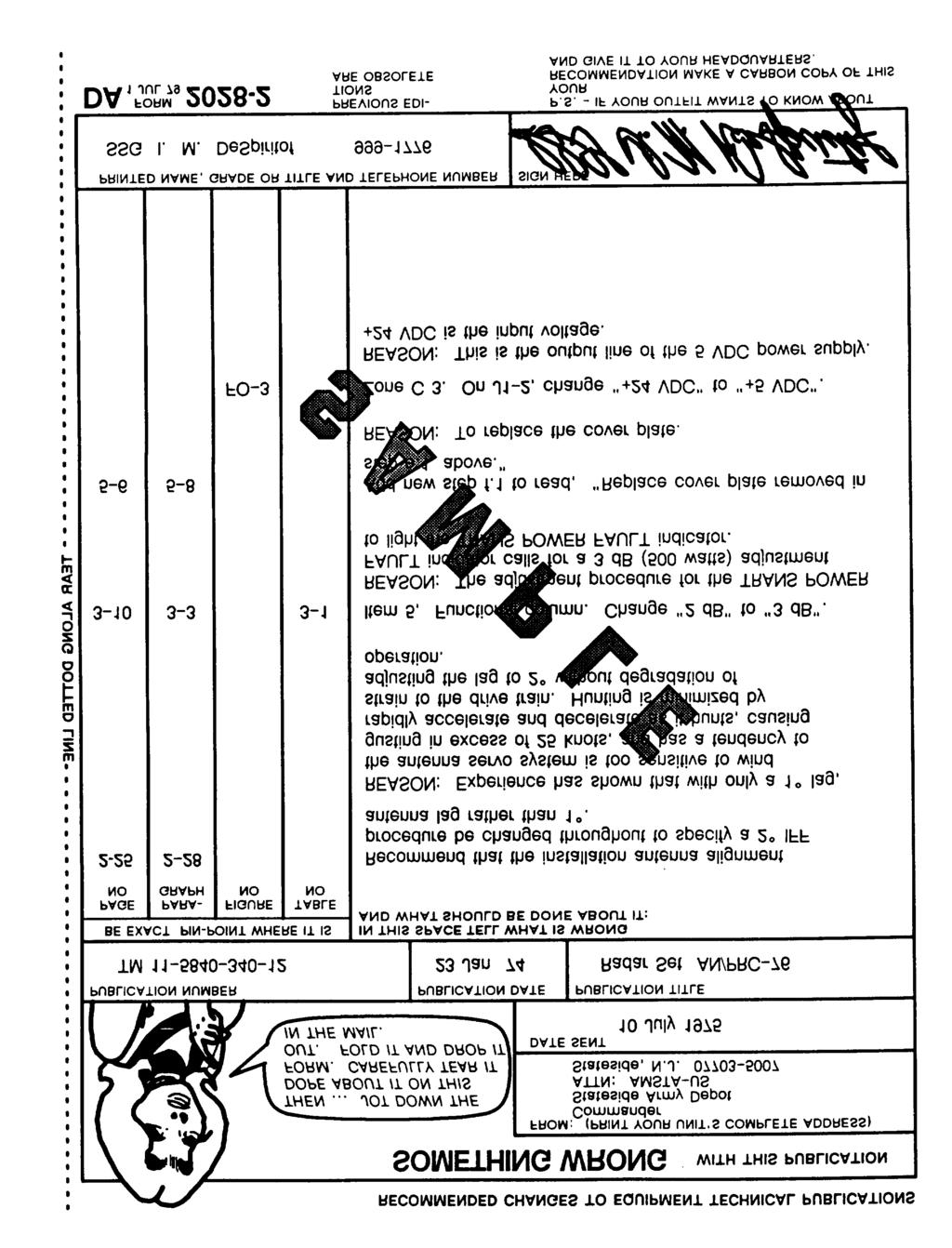
177
TM OPERATOR S MANUAL
 OPERATOR S MANUAL Approved for public release; distribution is unlimited. SINCGARS GROUND COMBAT NET RADIO, NON-ICOM MANPACK RADIO AN/PRC-119 (NSN 5820-01-151-9915) (EIC: L2A) SHORT RANGE VEHICULAR RADIO
TM POWER AMPLIFIER AM-6545A/GRC-193A (NSN )
") TECHNICAL MANUAL GENERAL SUPPORT MAINTENANCE MANUAL POWER AMPLIFIER AM-6545A/GRC-193A (NSN 5820-01-186-3699) HEADQUARTERS, DEPARTMENT OF THE ARMY 15 JANUARY 1986 \ Technical Manual No. 11-5820-921-40-2
TECHNICAL MANUAL GENERAL SUPPORT MAINTENANCE MANUAL POWER AMPLIFIER AM-6545A/GRC-193A (NSN 5820-01-186-3699) HEADQUARTERS, DEPARTMENT OF THE ARMY 15 JANUARY 1986 \ Technical Manual No. 11-5820-921-40-2
TECHNICAL MANUAL OPERATOR AND ORGANIZATIONAL MAINTENANCE MANUAL MEASURING SET, STANDING WAVE RATIO AN/USM-37E (NSN )
") TECHNICAL MANUAL OPERATOR AND ORGANIZATIONAL MAINTENANCE MANUAL MEASURING SET, STANDING WAVE RATIO AN/USM-37E (NSN 6625-00-197-6910) H E A D Q U A R T E R S, D E P A R T M E N T O F T H E A R M Y FEBRUARY
TECHNICAL MANUAL OPERATOR AND ORGANIZATIONAL MAINTENANCE MANUAL MEASURING SET, STANDING WAVE RATIO AN/USM-37E (NSN 6625-00-197-6910) H E A D Q U A R T E R S, D E P A R T M E N T O F T H E A R M Y FEBRUARY
TECHNICAL MANUAL OPERATOR S, ORGANIZATIONAL, DIRECT SUPPORT, AND GENERAL SUPPORT MAINTENANCE MANUAL TEST SET, RADIO AN/GRM-114 (NSN )
") TECHNICAL MANUAL OPERATOR S, ORGANIZATIONAL, DIRECT SUPPORT, AND GENERAL SUPPORT MAINTENANCE MANUAL TEST SET, RADIO AN/GRM-114 (NSN 6625-008-6206) HEADQUARTERS, DEPARTMENT OF THE ARMY JUNE 1982 This manual
TECHNICAL MANUAL OPERATOR S, ORGANIZATIONAL, DIRECT SUPPORT, AND GENERAL SUPPORT MAINTENANCE MANUAL TEST SET, RADIO AN/GRM-114 (NSN 6625-008-6206) HEADQUARTERS, DEPARTMENT OF THE ARMY JUNE 1982 This manual
TM OPERATOR S MANUAL
 OPERATOR S MANUAL Approved for public release; distribution is unlimited. SINCGARS GROUND COMBAT NET RADIO, NON-ICOM MANPACK RADIO AN/PRC-119 (NSN 5820-01-151-9915) (EIC: L2A) SHORT RANGE VEHICULAR RADIO
TECHNICAL MANUAL DIRECT AND GENERAL SUPPORT MAINTENANCE MANUAL FOR AUDIO FREQUENCY AMPLIFIER AM-1780B/VRC (NSN ) (EIC: N/A)
 (EIC: N/A)") TECHNICAL MANUAL DIRECT AND GENERAL SUPPORT MAINTENANCE MANUAL FOR AUDIO FREQUENCY AMPLIFIER AM-1780B/VRC (NSN 5895-01-284-3057) (EIC: N/A) Distribution authorized to US Government agencies and their contractors
TECHNICAL MANUAL DIRECT AND GENERAL SUPPORT MAINTENANCE MANUAL FOR AUDIO FREQUENCY AMPLIFIER AM-1780B/VRC (NSN 5895-01-284-3057) (EIC: N/A) Distribution authorized to US Government agencies and their contractors
TECHNICAL MANUAL OPERATOR S MANUAL SINCGARS GROUND COMBAT NET RADIO, ICOM
 TECHNICAL MANUAL OPERATOR S MANUAL SINCGARS GROUND COMBAT NET RADIO, ICOM MANPACK RADIO AN/PRC-119A (NSN 5820-01-267-9482) (EIC: L2Q) SHORT RANGE VEHICULAR RADIO AN/VRC-87A (NSN 5820-01-267-9480) (EIC:
RADIO SET AN/PRC-104(A) (NSN )
 (NSN )") TECHNICAL MANUAL GENERAL SUPPORT MAINTENANCE MANUAL RADIO SET AN/PRC-104(A) (NSN 5820-01-141-7953) HEADQUARTERS, DEPARTMENT OF THE ARMY 15 JANUARY 1986 Technical Manual No. 11-5820-919-40-1 HEADQUARTERS
TECHNICAL MANUAL GENERAL SUPPORT MAINTENANCE MANUAL RADIO SET AN/PRC-104(A) (NSN 5820-01-141-7953) HEADQUARTERS, DEPARTMENT OF THE ARMY 15 JANUARY 1986 Technical Manual No. 11-5820-919-40-1 HEADQUARTERS
REPORTING OF ERRORS AND RECOMMENDING IMPROVEMENTS
 TB 11-5820-890-10-10 DEPARTMENT OF THE ARMY TECHNICAL BULLETIN OPERATION OF DIGITAL MESSAGE DEVICE AN/PSG-5 (FIRE SUPPORT TEAM) WITH SINCGARS GROUND RADIO SET Headquarters, Department of the Army, Washington,
TECHNICAL MANUAL OPERATOR'S, ORGANIZATIONAL, DIRECT SUPPORT, AND GENERAL SUPPORT MAINTENANCE MANUAL (INCLUDING REPAIR PARTS AND SPECIAL TOOLS LIST)
") TM 11-6625-2781-14&P-5 TECHNICAL MANUAL OPERATOR'S, ORGANIZATIONAL, DIRECT SUPPORT, AND GENERAL SUPPORT MAINTENANCE MANUAL (INCLUDING REPAIR PARTS AND SPECIAL TOOLS LIST) FOR PLUG-IN, LOW FREQUENCY (SPECTRUM
TM 11-6625-2781-14&P-5 TECHNICAL MANUAL OPERATOR'S, ORGANIZATIONAL, DIRECT SUPPORT, AND GENERAL SUPPORT MAINTENANCE MANUAL (INCLUDING REPAIR PARTS AND SPECIAL TOOLS LIST) FOR PLUG-IN, LOW FREQUENCY (SPECTRUM
TM TECHNICAL MANUAL INTERMEDIATE (DIRECT SUPPORT) MAINTENANCE
 MAINTENANCE") TECHNICAL MANUAL INTERMEDIATE (DIRECT SUPPORT) MAINTENANCE RECEIVER-TRANSMITTER, RADIO RT-1439/VRC (NSN 5820-01-195-0827); AMPLIFIER-ADAPTER, VEHICULAR AM-7239/VRC (NSN 5895-01-188-8819); AMPLIFIER, RADIO
TECHNICAL MANUAL INTERMEDIATE (DIRECT SUPPORT) MAINTENANCE RECEIVER-TRANSMITTER, RADIO RT-1439/VRC (NSN 5820-01-195-0827); AMPLIFIER-ADAPTER, VEHICULAR AM-7239/VRC (NSN 5895-01-188-8819); AMPLIFIER, RADIO
TECHNICAL MANUAL DIRECT SUPPORT, GENERAL SUPPORT, AND DEPOT MAINTENANCE MANUAL RADIO SET AN/GRC-144 (NSN )
") TECHNICAL MANUAL DIRECT SUPPORT, GENERAL SUPPORT, AND DEPOT MAINTENANCE MANUAL RADIO SET AN/GRC-144 (NSN 5820-00-926-7356) This copy is a reprint which includes current pages from Changes 1 through 5.
TECHNICAL MANUAL DIRECT SUPPORT, GENERAL SUPPORT, AND DEPOT MAINTENANCE MANUAL RADIO SET AN/GRC-144 (NSN 5820-00-926-7356) This copy is a reprint which includes current pages from Changes 1 through 5.
TECHNICAL MANUAL OPERATOR S, ORGANIZATIONAL, DIRECT SUPPORT, AND GENERAL SUPPORT MAINTENANCE MANUAL INCLUDING REPAIR PARTS AND SPECIAL TOOLS LISTS
 TM 11-6625-2759-14 & P TECHNICAL MANUAL OPERATOR S, ORGANIZATIONAL, DIRECT SUPPORT, AND GENERAL SUPPORT MAINTENANCE MANUAL INCLUDING REPAIR PARTS AND SPECIAL TOOLS LISTS SPECTRUM ANALYZER PL-1391/U (TEKTRONIX
TM AN/GRA-39A NSN AN/GRA-39B NSN AN/GRA-39C NSN NSN
 TECHNICAL MANUAL DIRECT SUPPORT MAINTENANCE MANUAL FOR CONTROL, RADIO SET GROUPS AN/GRA-39 NSN 5820-00-889-3860 AN/GRA-39A NSN 5820-00-082-3998 AN/GRA-39B NSN 5820-00-949-9909 AN/GRA-39C NSN 5820-01-196-0204
VOLTMETER, DIGITAL AN/GSM-64C (NSN )
") TECHNICAL MANUAL OPERATOR S, ORGANIZATIONAL DIRECT SUPPORT, AND GENERAL SUPPORT MAINTENANCE MANUAL VOLTMETER, DIGITAL AN/GSM-64C (NSN6625-024-0834) HEADQUARTERS, DEPARTMENT OF THE ARMY 11 MARCH 1983 Technical
TECHNICAL MANUAL OPERATOR S, ORGANIZATIONAL DIRECT SUPPORT, AND GENERAL SUPPORT MAINTENANCE MANUAL VOLTMETER, DIGITAL AN/GSM-64C (NSN6625-024-0834) HEADQUARTERS, DEPARTMENT OF THE ARMY 11 MARCH 1983 Technical
TECHNICAL MANUAL OPERATOR S ORGANIZATIONAL, DIRECT SUPPORT, AND GENERAL SUPPORT MAINTENANCE MANUAL INCLUDING REPAIR PARTS AND SPECIAL TOOLS LIST FOR
 ARMY TM 11-6625-2827-14&P AIR FORCE TO 33A1-4-67-1 TECHNICAL MANUAL OPERATOR S ORGANIZATIONAL, DIRECT SUPPORT, AND GENERAL SUPPORT MAINTENANCE MANUAL INCLUDING REPAIR PARTS AND SPECIAL TOOLS LIST FOR ELECTROMAGNETIC
DEPARTMENT OF THE ARMY TECHNICAL BULLETIN OPERATION OF BATTERY COMPUTER SYSTEM AN/GYK-29 WITH SINCGARS GROUND RADIO SETS
 DEPARTMENT OF THE ARMY TECHNICAL BULLETIN OPERATION OF BATTERY COMPUTER SYSTEM AN/GYK-29 WITH SINCGARS GROUND RADIO SETS Headquarters, Department of the Army, Washington, DC 1 APRIL 1993 REPORTING OF ERRORS
Chapter 4 FH Networks
 Chapter 4 FH Networks 4-1. FH Variables a. SINCGARS hops or changes frequencies about 100 times per second. The radio uses digital processing to control the hopping sequence and the pattern so that the
Appendix Suggested SOP for SINCGARS SOP
 1. References: Appendix Suggested SOP for SINCGARS a. TM 11-5820-890-10-1. b. TM 11-5820-890-20-1. c. FM 11-32. SOP 2. Purpose: This suggested SOP establishes procedures and guidelines for operating the
TM ELECTRONIC EQUIPMENT CONFIGURATION ARMY MODEL OH-58A HELlCOPTER (NSN ) TECHNICAL MANUAL
 TECHNICAL MANUAL") TECHNICAL MANUAL DIRECT SUPPORT AND GENERAL SUPPORT MAINTENANCE MANUAL ELECTRONIC EQUIPMENT CONFIGURATION ARMY MODEL OH-58A HELlCOPTER (NSN 1520-00-169-7137) HEADQUARTERS, DEPARTMENT OF THE ARMY 31 DECEMBER
TECHNICAL MANUAL DIRECT SUPPORT AND GENERAL SUPPORT MAINTENANCE MANUAL ELECTRONIC EQUIPMENT CONFIGURATION ARMY MODEL OH-58A HELlCOPTER (NSN 1520-00-169-7137) HEADQUARTERS, DEPARTMENT OF THE ARMY 31 DECEMBER
RADIO SET AN/ARC-131 (NSN )
") TECHNICAL MANUAL AVIATION INTERMEDIATE MAINTENANCE MANUAL RADIO SET AN/ARC-131 (NSN 5821--937-4686) HEADQUARTERS, DEPARTMENT OF THE ARMY 13 SEPTEMBER 1985 SAFETY STEPS TO FOLLOW IF SOMEONE IS THE VICTIM
TECHNICAL MANUAL AVIATION INTERMEDIATE MAINTENANCE MANUAL RADIO SET AN/ARC-131 (NSN 5821--937-4686) HEADQUARTERS, DEPARTMENT OF THE ARMY 13 SEPTEMBER 1985 SAFETY STEPS TO FOLLOW IF SOMEONE IS THE VICTIM
TECHNICAL BULLETIN COMBAT NET RADIO
 TB -5820-890-20-3 TECHNICAL BULLETIN COMBAT NET RADIO INSTALLATION INSTRUCTIONS FOR INSTALLATION KIT, ELECTRONIC EQUIPMENT MK-2295/VRC (NSN 5895-0-295-2503) (EIC: N/A) TO PERMIT INSTALLATION OF RADIO SET
ARMY TM EE 150-NA-OPI-010/ E120-URC OPERATOR S MANUAL EQUIPMENT DESCRIPTION Page 1-6. OPERATOR S CONTROLS Page 2-1
 ARMY TM 11-5895-1195-10 AIR FORCE TO 31R2-2URC-71 NAVY EE 150-NA-OPI-010/ E120-URC100.1.4 OPERATOR S MANUAL EQUIPMENT DESCRIPTION Page 1-6 OPERATOR S CONTROLS Page 2-1 PMCS Page 2-10 OPERATION Page 2-13
EDACS WALL MOUNT STATION. Maintenance Manual. Mobile Communications LBI-31838A TABLE OF CONTENTS
 A Mobile Communications EDACS WALL MOUNT STATION TABLE OF CONTENTS SYSTEM BOARD & REGULATOR BOARD.......... LBI-31892 KEY/DISPLAY BOARD MAINTENANCE MANUAL.... LBI-31940 Maintenance Manual Printed in U.S.A.
DEPARTMENT OF THE ARMY TECHNICAL BULLETIN OPERATION OF SECURE NET RADIO INTERFACE UNIT TSEC/KY-90 WITH SINCGARS GROUND RADIO SETS
 TB 11-5820-890-10-7 DEPARTMENT OF THE ARMY TECHNICAL BULLETIN OPERATION OF SECURE NET RADIO INTERFACE UNIT TSEC/KY-90 WITH SINCGARS GROUND RADIO SETS Headquarters, Department of the Army, Washington, DC
TB TECHNICAL BULLETIN
 TECHNICAL BULLETIN INSTALLATION INSTRUCTIONS FOR INSTALLATION KIT, ELECTRONIC EQUIPMENT, MK-2848/VRC (NSN 5895-01-429-2066) (EIC: N/A) TO PERMIT INSTALLATION OF RADIO SET AN/VRC-89/91/92 SERIES IN A CARRIER,
TECHNICAL MANUAL DIRECT SUPPORT, GENERAL SUPPORT, AND DEPOT MAINTENANCE MANUAL INCLUDING REPAIR PARTS AND SPECIAL TOOLS LISTS RADIO SET AN/PRC-47
 TECHNICAL MANUAL DIRECT SUPPORT, GENERAL SUPPORT, AND DEPOT MAINTENANCE MANUAL INCLUDING REPAIR PARTS AND SPECIAL TOOLS LISTS RADIO SET AN/PRC-47 This copy is a reprint which includes current pages from
SINCGARS ICOM GROUND RADIO OPERATOR S POCKET GUIDE
 TM 11-5820-890-10-2 SINCGARS ICOM GROUND RADIO OPERATOR S POCKET GUIDE RADIO SETS MANPACK RADIO (NSN: N/A) (EIC:N/A) VEHICULAR RADIOSI (AN/VRC-87A/C THRU AN/VRC-92A) (NSN: N/A) (EIC: N/A) OPERATOR ROADMAP
AB Drives AN/ARC-182(V) UHF/VHF Airborne. Key Features
 UHF/VHF Airborne. Key Features") UHF/VHF Airborne Key Features 11,600 channels, 25-kHz spacing Direct MIL-STD-1553B multiplex system control 28 or 30 preset channels, nonvolatile Automatic direction finding compatible memory Four guard
UHF/VHF Airborne Key Features 11,600 channels, 25-kHz spacing Direct MIL-STD-1553B multiplex system control 28 or 30 preset channels, nonvolatile Automatic direction finding compatible memory Four guard
TB TECHNICAL BULLETIN
 TECHNICAL BULLETIN TB 11-5820-890-20-98 INSTALLATION INSTRUCTIONS FOR INSTALLATION KIT, ELECTRONIC EQUIPMENT, MK-2837/VRC (NSN 5895-01-421-0811) (EIC: N/A) TO PERMIT INSTALLATION OF RADIO SET AN/VRC-87/88/90
TECHNICAL MANUAL OPERATOR S, ORGANIZATIONAL, DIRECT SUPPORT, AND GENERAL SUPPORT MAINTENANCE MANUAL
 TECHNICAL MANUAL OPERATOR S, ORGANIZATIONAL, DIRECT SUPPORT, AND GENERAL SUPPORT MAINTENANCE MANUAL EQUIPMENT DESCRIPTION 1-5 ASSEMBLY AND INSTALLATION 4-5 REMOVAL OF EQUIPMENT 4-67 INDEX Index-1 ELECTRONICS
UNITED STATES MARINE CORPS FIELD MEDICAL TRAINING BATTALION Camp Lejeune, NC
 UNITED STATES MARINE CORPS FIELD MEDICAL TRAINING BATTALION Camp Lejeune, NC 28542-0042 FMSO 108 Communicate with a VHF Radio TERMINAL LEARNING OBJECTIVE. 1. Given a SL-3 complete VHF radio with a fill,
TECHNICAL MANUAL OPERATOR S AND UNIT MAINTENANCE MANUAL FOR FIRING DEVICE, DEMOLITION. M122 (NSN ) (EIC: 2NA)
 (EIC: 2NA)") ARMY TM 9-1375-213-12-3 AIR FORCE TECHNICAL MANUAL OPERATOR S AND UNIT MAINTENANCE MANUAL FOR FIRING DEVICE, DEMOLITION. M122 (NSN 1375-01-021-0606) (EIC: 2NA) DISTRIBUTION STATEMENT A: Approved for public
ARMY TM 9-1375-213-12-3 AIR FORCE TECHNICAL MANUAL OPERATOR S AND UNIT MAINTENANCE MANUAL FOR FIRING DEVICE, DEMOLITION. M122 (NSN 1375-01-021-0606) (EIC: 2NA) DISTRIBUTION STATEMENT A: Approved for public
TB TECHNICAL BULLETIN
 TECHNICAL BULLETIN INSTALLATION INSTRUCTIONS FOR INSTALLATION KIT, ELECTRONIC EQUIPMENT, MK-2334/VRC (NSN 5895-01-285-2348) (EIC: N/A) TO PERMIT INSTALLATION OF RADIO SET AN/VRC-92 SERIES INTO TRUCK, VAN,
TECHNICAL MANUAL. Approved for Public Release; Distribution is unlimited
 TM -580-890-30P- TECHNICAL MANUAL DIRECT SUPPORT MAINTENANCE REPAIR PARTS AND SPECIAL TOOLS LIST RECEIVER-TRANSMITTER, RADIO RT- 53A(C)/U (NSN 580-0-38-7990) (EIC: N/A) RECEIVER-TRANSMITTER,RADIO RT- 53D(C)/U
TECHNICAL MANUAL UNIT MAINTENANCE MANUAL GROUND ICOM RADIO SETS
 TECHNICAL MANUAL UNIT MAINTENANCE MANUAL INTRODUCTION PAGE 1-1 MANPACK RADIO PAGE 2-1 VEHICULAR RADIOS PAGE 3-1 CABLES PAGE 4-1 COMPONENT REPLACEMENT/REPAIR PAGE 5-1 GROUND ICOM RADIO SETS AN/PRC-119A
Chapter 5 SINCGARS Planning
 Chapter 5 SINCGARS Planning 5-1. Network Requirements a. The initial operations plan and unit SOP determine the type of net needed. The network planner must answer the following questions when planning
RADIO SET AN/PRC-127 (NSN )
") I OPERATOR S TM 11-5820-I 048-110 DEPARTMENT OF THE ARMY MANUAL PMCS OPERATION l RADIO SET AN/PRC-127 (NSN 5820-01-266-5964) 1 JANUARY 1991 Distribution authorized to the Department of Defense and DOD
I OPERATOR S TM 11-5820-I 048-110 DEPARTMENT OF THE ARMY MANUAL PMCS OPERATION l RADIO SET AN/PRC-127 (NSN 5820-01-266-5964) 1 JANUARY 1991 Distribution authorized to the Department of Defense and DOD
TB TECHNICAL BULLETIN
 TB 11-5820-890-20-102 TECHNICAL BULLETIN INSTALLATION INSTRUCTIONS FOR INSTALLATION KIT, ELECTRONIC EQUIPMENT, MK-2845/VRC (NSN 5895-01-441-1334) (EIC: N/A) TO PERMIT INSTALLATION OF RADIO SET AN/VRC-87/88/90
DEPARTMENT OF THE ARMY TECHNICAL BULLETIN OPERATION OF MORTAR BALLISTIC COMPUTER M23 WITH SINCGARS GROUND RADIO SETS
 TB 11-5820-890-10-13 DEPARTMENT OF THE ARMY TECHNICAL BULLETIN OPERATION OF MORTAR BALLISTIC COMPUTER M23 WITH SINCGARS GROUND RADIO SETS Headquarters, Department of the Army, Washington, DC 1 APRIL 1993
TECHNICAL BULLETIN INSTALLATION INSTRUCTIONS FOR MAST AB-1386/U (NSN ) (EIC: N/A)
 (EIC: N/A)") TECHNICAL BULLETIN INSTALLATION INSTRUCTIONS FOR MAST AB-1386/U (NSN 5985-01-381-6341) (EIC: N/A) ON Utility Truck: Cargo/Troop Carrier, 1-1/4 Ton, 4x4, M998 Utility Truck: Cargo/Troop Carrier, 1-1/4 Ton,
TECHNICAL BULLETIN INSTALLATION INSTRUCTIONS FOR MAST AB-1386/U (NSN 5985-01-381-6341) (EIC: N/A) ON Utility Truck: Cargo/Troop Carrier, 1-1/4 Ton, 4x4, M998 Utility Truck: Cargo/Troop Carrier, 1-1/4 Ton,
TECHNICAL MANUAL OPERATOR S AND UNIT MAINTENANCE MANUAL FOR FIRING DEVICE, DEMOLITION. M122 (NSN ) (EIC: 2NA)
 (EIC: 2NA)") ARMY TM 9-1375-213-12-3 AIR FORCE TECHNICAL MANUAL OPERATOR S AND UNIT MAINTENANCE MANUAL FOR FIRING DEVICE, DEMOLITION. M122 (NSN 1375-01-021-0606) (EIC: 2NA) DISTRIBUTION STATEMENT A: Approved for public
ARMY TM 9-1375-213-12-3 AIR FORCE TECHNICAL MANUAL OPERATOR S AND UNIT MAINTENANCE MANUAL FOR FIRING DEVICE, DEMOLITION. M122 (NSN 1375-01-021-0606) (EIC: 2NA) DISTRIBUTION STATEMENT A: Approved for public
TB TECHNICAL BULLETIN
 TB 11-5820-890-20-101 TECHNICAL BULLETIN INSTALLATION INSTRUCTIONS FOR INSTALLATION KIT, ELECTRONIC EQUIPMENT, MK-2400/VRC (NSN 5895-01-421-0814) (EIC: N/A) TO PERMIT INSTALLATION OF RADIO SET AN/VRC-87/88/90
ARMY TM EE640-CA-MMI-150/E154 CPU TECHNICAL MANUAL
 ARMY TM 11-5895-856-34-15 NAVY EE640-CA-MMI-150/E154 CPU AIR FORCE TO 31W2-2T-122-15 TECHNICAL MANUAL DIRECT SUPPORT AND GENERAL SUPPORT MAINTENANCE MANUAL FOR CENTRAL, MESSAGE SWITCHING, AUTOMATIC AN/TYC-39(V)1
DEPARTMENT OF THE ARMY TECHNICAL MANUAL. This copy is a reprint which includes current pages from Changes 1 through 8.
 DEPARTMENT OF THE ARMY TECHNICAL MANUAL DIRECT SUPPORT, GENERAL SUPPORT, AND DEPOT MAINTENANCE MANUAL TEST FACILITIES KIT MK-994/AR This copy is a reprint which includes current pages from Changes 1 through
TECHNICAL MANUAL UNIT, DIRECT SUPPORT AND GENERAL SUPPORT MAINTENANCE MANUAL (INCLUDING REPAIR PARTS AND SPECIAL TOOLS LIST)
") TM 11-5820-1048-24 TECHNICAL MANUAL UNIT, DIRECT SUPPORT AND GENERAL SUPPORT MAINTENANCE MANUAL (INCLUDING REPAIR PARTS AND SPECIAL TOOLS LIST) UNIT PREVENTIVE MAINTENANCE CHECKS AND SERVICES (PMCS) 2-27
TM 11-5820-1048-24 TECHNICAL MANUAL UNIT, DIRECT SUPPORT AND GENERAL SUPPORT MAINTENANCE MANUAL (INCLUDING REPAIR PARTS AND SPECIAL TOOLS LIST) UNIT PREVENTIVE MAINTENANCE CHECKS AND SERVICES (PMCS) 2-27
UNIT MAINTENANCE REPAIR PARTS AND SPECIAL TOOLS LIST
 UNIT MAINTENANCE REPAIR PARTS AND SPECIAL TOOLS LIST FOR RADIO SETS AN/PRC-119 (NSN 5820-01-151-9915)(EIC: L2A) AN/PRC-119A (NSN 5820-01-267-9482)(EIC: L2Q) AN/PRC-119D (NSN 5820-01-421-0801)(EIC: GC9)
LBI-31564A. Mobile Communications. DELTA - SX MHz RADIO COMBINATIONS (NEGATIVE GROUND ONLY) Maintenance Manual
 Maintenance Manual") A Mobile Communications DELTA - SX 136-174 MHz RADIO COMBINATIONS (NEGATIVE GROUND ONLY) Maintenance Manual TABLE OF CONTENTS MILITARY AND SYSTEM SPECIFICATIONS................................. 2-3 COMBINATION
A Mobile Communications DELTA - SX 136-174 MHz RADIO COMBINATIONS (NEGATIVE GROUND ONLY) Maintenance Manual TABLE OF CONTENTS MILITARY AND SYSTEM SPECIFICATIONS................................. 2-3 COMBINATION
DEPARTMENT OF THE ARMY TECHNICAL BULLETIN OPERATION OF AN/TPQ-36, FIREFINDER, WITH SINCGARS GROUND RADIO SETS
 TB 11-5820-890-10-15 DEPARTMENT OF THE ARMY TECHNICAL BULLETIN OPERATION OF AN/TPQ-36, FIREFINDER, WITH SINCGARS GROUND RADIO SETS Headquarters, Department of the Army, Washington, DC 1 APRIL 1993 REPORTING
TM OPERATOR S MANUAL
 OPERATOR S MANUAL EQUIPMENT DESCRIPTION PAGE 1-5 OPERATING INSTRUCTIONS PAGE 2-1 PMCS PAGE 2-3 TROUBLESHOOTING PROCEDURE PAGE 3-1 MAINTENANCE PROCEDURES PAGES 3-2 CABLE ASSEMBLY, SPECIAL PURPOSE, ELECTRICAL
VHF Transceiver AR6201
 VHF Transceiver AR6201 Operating Instructions Issue 2 / October 2010 Article No. 0618.764-071 Becker Flugfunkwerk GmbH Baden-Airpark B 108 77836 Rheinmünster Germany Telefon / Telephone +49 (0) 7229 /
DEPARTMENT OF THE ARMY TECHNICAL MANUAL
 DEPARTMENT OF THE ARMY TECHNICAL MANUAL OPERATOR, ORGANIZATIONAL DS, GS, AND DEPOT MAINTENANCE MANUAL OSCILLOSCOPE AN/USM-182A This copy is a reprint which includes current pages from Change 1. HEADQUARTERS,
ANTENNA AS-1729/VRC (NSN )
") TECHNICAL MANUAL This copy is a reprint which includes current pages from Change 1. OPERATOR S, ORGANIZATIONAL, DIRECT SUPPORT, AND GENERAL SUPPORT MAINTENANCE MANUAL OPERATING INSTRUCTIONS PAGE 2-1 OPERATOR
TECHNICAL MANUAL This copy is a reprint which includes current pages from Change 1. OPERATOR S, ORGANIZATIONAL, DIRECT SUPPORT, AND GENERAL SUPPORT MAINTENANCE MANUAL OPERATING INSTRUCTIONS PAGE 2-1 OPERATOR
TM TEST SET, ELECTRONIC CIRCUIT PLUG-IN UNIT AN/ARM-87 (NSN ) TECHNICAL MANUAL
 TECHNICAL MANUAL") TECHNICAL MANUAL DIRECT SUPPORT AND GENERAL SUPPORT MAINTENANCE MANUAL TEST SET, ELECTRONIC CIRCUIT PLUG-IN UNIT AN/ARM-87 (NSN 6625-00-908-0358) HEADQUARTERS, DEPARTMENT OF THE ARMY 16 SEPTEMBER 1981
TECHNICAL MANUAL DIRECT SUPPORT AND GENERAL SUPPORT MAINTENANCE MANUAL TEST SET, ELECTRONIC CIRCUIT PLUG-IN UNIT AN/ARM-87 (NSN 6625-00-908-0358) HEADQUARTERS, DEPARTMENT OF THE ARMY 16 SEPTEMBER 1981
TECHNICAL MANUAL OPERATOR, ORGANIZATIONAL, DIRECT SUPPORT, GENERAL SUPPORT, AND DEPOT MAINTENANCE MANUAL
 TECHNICAL MANUAL OPERATOR, ORGANIZATIONAL, DIRECT SUPPORT, GENERAL SUPPORT, AND DEPOT MAINTENANCE MANUAL RADIO SET AN/FRC-109 (V) (NSN 5820-00-192-2372) (LENKURT ELECTRIC 76-CLASS MICROWAVE RADIO ASSEMBLIES)
UNITED STATES ARMY AVIATION CENTER FORT RUCKER, ALABAMA JUNE 2011
 UNITED STATES ARMY AVIATION CENTER FORT RUCKER, ALABAMA JUNE 2011 STUDENT HANDOUT TITLE: AH64D ENGINES AND RELATED SYSTEMS FILE NUMBER: 11-0909-4.0 (LOT13) PROPONENT FOR THIS STUDENT HANDOUT IS: COMMANDER,
DEPARTMENT OF THE ARMY TECHNICAL BULLETIN CALIBRATION PROCEDURE FOR SHF SIGNAL GENERATOR AN/USM-47 (HEWLETT-PACKARD MODEL 626A) (NSN )
 (NSN )") DEPARTMENT OF THE ARMY TECHNICAL BULLETIN CALIBRATION PROCEDURE FOR SHF SIGNAL GENERATOR AN/USM-47 (HEWLETT-PACKARD MODEL 626A) (NSN 6625-00-455-6917) Headquarters, Department of the Army, Washington,
DEPARTMENT OF THE ARMY TECHNICAL BULLETIN CALIBRATION PROCEDURE FOR SHF SIGNAL GENERATOR AN/USM-47 (HEWLETT-PACKARD MODEL 626A) (NSN 6625-00-455-6917) Headquarters, Department of the Army, Washington,
TEST SET TRANSPONDER SET AN/APM - 305A (NSN )
") TM 11 6625-2611-40 TECHNICAL MANUAL DIRECT AND GENERAL SUPPORT MAINTENANCE MANUAL FOR TEST SET TRANSPONDER SET AN/APM - 305A (NSN 6625-01-052-3881) HEADQUARTERS, DEPARTMENT OF THE ARMY OCTOBER 1978 TM
TM 11 6625-2611-40 TECHNICAL MANUAL DIRECT AND GENERAL SUPPORT MAINTENANCE MANUAL FOR TEST SET TRANSPONDER SET AN/APM - 305A (NSN 6625-01-052-3881) HEADQUARTERS, DEPARTMENT OF THE ARMY OCTOBER 1978 TM
Technical Equipment Specification
 STATE OF CALIFORNIA Office of the State Chief Information Officer Public Safety Communications Division Technical Equipment Specification Equipment Type: Transmitter/Receiver Mobile Relay/Base/Control
TB TECHNICAL BULLETIN
 TECHNICAL BULLETIN INSTALLATION INSTRUCTIONS FOR INSTALLATION KIT, ELECTRONIC EQUIPMENT MK-2865/VRC (NSN 5895-01-442-4585) (EIC: N/A) TO PERMIT INSTALLATION OF MULTIPLEXER, FREQUENCY HOPPING TD-1456/VRC
ARCHIVED REPORT. For data and forecasts on current programs please visit or call
 Airborne Electronics Forecast ARCHIVED REPORT For data and forecasts on current programs please visit www.forecastinternational.com or call +1 203.426.0800 ARC-182(V) - Archived 9/2001 Outlook No longer
TECHNICAL MANUAL DIRECT SUPPORT AND GENERAL SUPPORT MAINTENANCE MANUAL FLIGHT COORDINATION CENTRAL AN/TSC-61B (NSN )
") TECHNICAL MANUAL DIRECT SUPPORT AND GENERAL SUPPORT MAINTENANCE MANUAL FLIGHT COORDINATION CENTRAL AN/TSC-61B (NSN 5895-01-057-3968) HEADQUARTERS, DEPARTMENT OF THE ARMY 12 MARCH 1980 WARNINGS HIGH VOLTAGE
TECHNICAL MANUAL DIRECT SUPPORT AND GENERAL SUPPORT MAINTENANCE MANUAL FLIGHT COORDINATION CENTRAL AN/TSC-61B (NSN 5895-01-057-3968) HEADQUARTERS, DEPARTMENT OF THE ARMY 12 MARCH 1980 WARNINGS HIGH VOLTAGE
ARMY MODEL UH-1H/V HELICOPTERS
 OPERATOR S MANUAL ARMY MODEL UH-1H/ HELICOPTERS This manual supersedes TM 55-1520-210-10 dated 1 December 1986, including all changes. HEADQUARTERS, DEPARTMENT OF THE ARMY 15 FEBRUARY 1988 TECHNICAL MANUAL
OPERATOR, UNIT MAINTENANCE, AND DIRECT SUPPORT MAINTENANCE MANUAL (INCLUDING REPAIR PARTS AND SPECIAL TOOLS LIST) FOR EARTH AUGER ASSEMBLY
 FOR EARTH AUGER ASSEMBLY") OPERATOR, UNIT MAINTENANCE, AND DIRECT SUPPORT MAINTENANCE MANUAL (INCLUDING REPAIR PARTS AND SPECIAL TOOLS LIST) FOR EARTH AUGER ASSEMBLY MODEL 1650EH-MS LOWE Manufacturing Company NSN 2590-01-384-6857
OPERATOR, UNIT MAINTENANCE, AND DIRECT SUPPORT MAINTENANCE MANUAL (INCLUDING REPAIR PARTS AND SPECIAL TOOLS LIST) FOR EARTH AUGER ASSEMBLY MODEL 1650EH-MS LOWE Manufacturing Company NSN 2590-01-384-6857
TM &P TECHNICAL MANUAL OPERATOR S, ORGANIZATIONAL, DIRECT SUPPORT AND GENERAL SUPPORT MAINTENANCE MANUAL (INCLUDING REPAIR PARTS
 TM11-4920-296-14&P TECHNICAL MANUAL OPERATOR S, ORGANIZATIONAL, DIRECT SUPPORT AND GENERAL SUPPORT MAINTENANCE MANUAL (INCLUDING REPAIR PARTS AND SPECIAL TOOLS LIST) FOR TRANSPONDER SET, TEST SET AN/APM-378
FREQUENCY SELECTIVE LEVEL METER AN/USM-490 (NSN ) (EIC: N/A)
 (EIC: N/A)") TECHNICAL MANUAL OPERATOR S AND ORGANIZATIONAL MAINTENANCE MANUAL FOR FREQUENCY SELECTIVE LEVEL METER AN/USM-490 (NSN 6625-01-138-3351) (EIC: N/A) DISTRIBUTION STATEMENT A Approved for Public Release;
TECHNICAL MANUAL OPERATOR S AND ORGANIZATIONAL MAINTENANCE MANUAL FOR FREQUENCY SELECTIVE LEVEL METER AN/USM-490 (NSN 6625-01-138-3351) (EIC: N/A) DISTRIBUTION STATEMENT A Approved for Public Release;
TECHNICAL MANUAL GENERAL SUPPORT MAINTENANCE MANUAL FOR TEST SET, ELECTRONIC CIRCUIT PLUG-IN UNIT TS-3317( )/TSQ-73 (NSN
/TSQ-73 (NSN") ARMY TM 11-7010-201-40-2 NAVY ET821-AA-MMI-020/E154 MTS AIR FORCE T.O. 31S5-2TSQ73-2-2 TECHNICAL MANUAL GENERAL SUPPORT MAINTENANCE MANUAL FOR TEST SET, ELECTRONIC CIRCUIT PLUG-IN UNIT TS-3317( )/TSQ-73
ARMY TM 11-7010-201-40-2 NAVY ET821-AA-MMI-020/E154 MTS AIR FORCE T.O. 31S5-2TSQ73-2-2 TECHNICAL MANUAL GENERAL SUPPORT MAINTENANCE MANUAL FOR TEST SET, ELECTRONIC CIRCUIT PLUG-IN UNIT TS-3317( )/TSQ-73
Installation & Operation Manual SAGA1-K Series Industrial Radio Remote Control
 Installation & Operation Manual SAGA1-K Series Industrial Radio Remote Control Gain Electronic Co. Ltd. Table Of Contents Safety Considerations ------------------------------------------------------------2
TM Use gloves, sleeves and an apron which the solvent cannot penetrate. If the solvent is taken internally, see a doctor immediately.
 DANGEROUS VOLTAGES EXIST IN THIS EQUIPMENT Voltages as high as 128 volts ac, 3,000 volts dc, and 10,000 volts RF are used in the operation of Amplifier, Radio Frequency AM-3349/GRC-106. Be careful when
AT RF20 MultiBand Handheld Transceiver
 AT RF20 MultiBand Handheld Transceiver AT RF20 MultiBand Handheld Transceiver AT RF20 ECCM handheld multiband transceiver with improved resistance to electronic warfare is designated for use at the lowest
ARMY TM NAVY EE150-SN-OPl-010/E110-PRC 70 OPERATOR S MANUAL RADIO SET AN/PRC-70 (NSN )
") ARMY TM 11-5820-553-10 NAVY EE150-SN-OPl-010/E110-PRC 70 OPERATOR S MANUAL RADIO SET AN/PRC-70 (NSN 5820-01-062-8246) This copy is a reprint which includes current pages from Changes 1 and 2. DEPARTMENTS
ARMY TM 11-5820-553-10 NAVY EE150-SN-OPl-010/E110-PRC 70 OPERATOR S MANUAL RADIO SET AN/PRC-70 (NSN 5820-01-062-8246) This copy is a reprint which includes current pages from Changes 1 and 2. DEPARTMENTS
HydroLynx Systems, Inc.
 Model 50386R-RP Receiver and Repeater Instruction Manual Document No: A102684 Document Revision Date: August, 2006 Receiving and Unpacking Carefully unpack all components and compare to the packing list.
TECHNICAL MANUAL (NSN ) This copy is a reprint which includes current pages from Change 1.
 This copy is a reprint which includes current pages from Change 1.") TM 11-6625-3135-12 TECHNICAL MANUAL OPERATOR S AND ORGANIZATIONAL MAINTENANCE MANUAL OSCILLOSCOPE AN/USM-488 (NSN 6625-01-1 87-7847) This copy is a reprint which includes current pages from Change 1. 4
TM 11-6625-3135-12 TECHNICAL MANUAL OPERATOR S AND ORGANIZATIONAL MAINTENANCE MANUAL OSCILLOSCOPE AN/USM-488 (NSN 6625-01-1 87-7847) This copy is a reprint which includes current pages from Change 1. 4
Maintenance Manual. MTD SERIES 900 MHz, 10-WATT, DATA ONLY MOBILE RADIO. Mobile Communications LBI TABLE OF CONTENTS
 Mobile Communications MTD SERIES 900 MHz, 10-WATT, DATA ONLY MOBILE RADIO TABLE OF CONTENTS RF BOARD............................... LBI-38545 AUDIO BOARD............................ LBI-38546 LOGIC BOARD............................
DIGITAL MULTIMETER AN/PSM-45A (NSN ) (EIC: N/A)
 (EIC: N/A)") TECHNICAL MANUAL OPERATOR S, UNIT, INTERMEDIATE DIRECT SUPPORT, AND GENERAL SUPPORT MAINTENANCE MANUAL EQUIPMENT DESCRIPTION PAGE 1-2 OPERATOR S CONTROLS PAGE 2-1 OPERATION PAGE 2-4 UNIT TROUBLESHOOTING
TECHNICAL MANUAL OPERATOR S, UNIT, INTERMEDIATE DIRECT SUPPORT, AND GENERAL SUPPORT MAINTENANCE MANUAL EQUIPMENT DESCRIPTION PAGE 1-2 OPERATOR S CONTROLS PAGE 2-1 OPERATION PAGE 2-4 UNIT TROUBLESHOOTING
OPERATING INSTRUCTIONS. VHF Transceiver AR Subject to technical changes
 OPERATING INSTRUCTIONS VHF Transceiver AR 3209 BECKER FLUGFUNKWERK GMBH Baden Airpark D-77836 Rheinmünster (Germany) Tel.: +49 (0) 7229 / 305-0 Fax: +49 (0) 7229 / 305-217 Subject to technical changes
MODEM LOW SPEED WIRE LINE MD-674(P)/G
/G") DEPARTMENT OF THE ARMY TECHNICAL MANUAL TM 11-5805-424-15 DEPARTMENT OF THE NAVY PUBLICATION NAVSHIPS 0967-220-9010 DEPARTMENT OF THE AIR FORCE TECHNICAL ORDER TO 31W2-2G-41 OPERATOR'S ORGANIZATIONAL,
DEPARTMENT OF THE ARMY TECHNICAL MANUAL TM 11-5805-424-15 DEPARTMENT OF THE NAVY PUBLICATION NAVSHIPS 0967-220-9010 DEPARTMENT OF THE AIR FORCE TECHNICAL ORDER TO 31W2-2G-41 OPERATOR'S ORGANIZATIONAL,
Dear Valued Customer,
 Dear Valued Customer, Thank you for choosing Listen! All of us at Listen are dedicated to provide you with the highest quality products available. We take great pride in their outstanding performance because
VHF Transceiver AR6201-(X0X) Software Versions: SCI1050S305 Version 3.05 SCI1051S305 Version 1.49 and upwards
 Software Versions: SCI1050S305 Version 3.05 SCI1051S305 Version 1.49 and upwards") VHF Transceiver AR6201-(X0X) Software Versions: SCI1050S305 Version 3.05 SCI1051S305 Version 1.49 and upwards Operating Instructions Issue 5 / November 2013 Article No. 0618.764-071 Becker Avionics GmbH
VHF Transceiver AR6201-(X0X) Software Versions: SCI1050S305 Version 3.05 SCI1051S305 Version 1.49 and upwards Operating Instructions Issue 5 / November 2013 Article No. 0618.764-071 Becker Avionics GmbH
A Covert Tracking System Using the DDF5931
 1.0 Introduction A Covert Tracking System Using the DDF5931 A Technical Application Note from Doppler Systems April 25, 2004 This application note describes a simple covert tracking system using the Doppler
DEPARTMENT OF THE ARMY TECHNICAL BULLETIN
 *TB 9-6625-1356-24 DEPARTMENT OF THE ARMY TECHNICAL BULLETIN CALIBRATION PROCEDURE FOR TEST OSCILLATOR, HEWLETT-PACKARD MODELS 651A, 651B AND 652A (SG-763/U) Headquarters Department of the Army, Washington,
User Manual. ilive 2 Wireless microphone system
 User Manual ilive 2 Wireless microphone system Safety instructions When using this electronic device, basic precautions should always be taken, including the following: 1 Read all instructions before using
USER MANUAL Universal Gateway U9921-GUV (P/N: 40994G-01)
") USER MANUAL Universal Gateway U9921-GUV (P/N: 40994G-01) 2012 DAVID CLARK COMPANY INCORPORATED Cautions and Warnings READ AND SAVE THESE INSTRUCTIONS. Follow the instructions in this installation manual.
USER MANUAL Universal Gateway U9921-GUV (P/N: 40994G-01) 2012 DAVID CLARK COMPANY INCORPORATED Cautions and Warnings READ AND SAVE THESE INSTRUCTIONS. Follow the instructions in this installation manual.
Summary Report for Individual Task E-1702 Test the AN/PRC-112(*) Status: Approved
 Status: Approved") Report Date: 29 Apr 2012 Summary Report for Individual Task 091-94E-1702 Test the AN/PRC-112(*) Status: DISTRIBUTION RESTRICTION: for public release; distribution is unlimited. DESTRUCTION NOTICE: ne Page
Report Date: 29 Apr 2012 Summary Report for Individual Task 091-94E-1702 Test the AN/PRC-112(*) Status: DISTRIBUTION RESTRICTION: for public release; distribution is unlimited. DESTRUCTION NOTICE: ne Page
SPECTRUM ANALYZER AN/USM-489(V)1 ( )
1 ( )") TECHNICAL MANUAL GENERAL SUPPORT MAINTENANCE SPECTRUM ANALYZER AN/USM-489(V)1 (6625-01-079-9495) HEADQUARTERS, DEPARTMENT OF THE ARMY 1 MARCH 1987 SAFETY STEPS TO FOLLOW IF SOMEONE IS THE VICTIM OF ELECTRICAL
TECHNICAL MANUAL GENERAL SUPPORT MAINTENANCE SPECTRUM ANALYZER AN/USM-489(V)1 (6625-01-079-9495) HEADQUARTERS, DEPARTMENT OF THE ARMY 1 MARCH 1987 SAFETY STEPS TO FOLLOW IF SOMEONE IS THE VICTIM OF ELECTRICAL
TECHNICAL MANUAL OPERATOR, UNIT, DIRECT SUPPORT AND GENERAL SUPPORT MAINTENANCE MANUAL (INCLUDING REPAIR PARTS AND SPECIAL TOOLS LIST) FOR
 FOR") *TM 55-1930-209-14&P-12 TECHNICAL MANUAL OPERATOR, UNIT, DIRECT SUPPORT AND GENERAL SUPPORT MAINTENANCE MANUAL (INCLUDING REPAIR PARTS AND SPECIAL TOOLS LIST) FOR WATER PURIFICATION BARGES (NSN 1930-01-234-2165)
*TM 55-1930-209-14&P-12 TECHNICAL MANUAL OPERATOR, UNIT, DIRECT SUPPORT AND GENERAL SUPPORT MAINTENANCE MANUAL (INCLUDING REPAIR PARTS AND SPECIAL TOOLS LIST) FOR WATER PURIFICATION BARGES (NSN 1930-01-234-2165)
AMPLIFIER, POWER AM-7301/GRC-215 (NSN )
") UNIT, INTERMEDIATE DIRECT SUPPORT AND GENERAL SUPPORT MAINTENANCE MANUAL ARMY TM 11-5895-1319-24 NAVY EE020-FH-MMI-010/W110-AM7301 AIR FORCE TO 31R2-4-574-2 HOW TO USE THIS MANUAL iii EQUIPMENT DESCRIPTION
UNIT, INTERMEDIATE DIRECT SUPPORT AND GENERAL SUPPORT MAINTENANCE MANUAL ARMY TM 11-5895-1319-24 NAVY EE020-FH-MMI-010/W110-AM7301 AIR FORCE TO 31R2-4-574-2 HOW TO USE THIS MANUAL iii EQUIPMENT DESCRIPTION
Model: TP380 User Manual
 Model: TP380 User Manual 1 UHF RADIO TRANSCEIVER MODEL: TP380 USER MANUAL INTRODUCTION Thank you for selecting the Oregon Scientific TP380 as your product of choice. This product is a portable, easy-to-use
3521 B 6 Vehicle Set VHF FM VEHICLE RADIO. VEHICLE SETS
 www.radmor.com RADMOR S.A. Hutnicza 3 81-212 Gdynia, Poland Foreign Customers Department: tel. +4858 69 96 621, fax: +4858 69 96 622 e-mail: export@radmor.com.pl VHF FM VEHICLE RADIO 3521 B 6 Vehicle Set
TECHNICAL MANUAL UNIT AND INTERMEDIATE DIRECT SUPPORT AND GENERAL SUPPORT MAINTENANCE MANUAL (INCLUDING REPAIR PARTS AND SPECIAL TOOLS LIST)
") TECHNICAL MANUAL UNIT AND INTERMEDIATE DIRECT SUPPORT AND GENERAL SUPPORT MAINTENANCE MANUAL (INCLUDING REPAIR PARTS AND SPECIAL TOOLS LIST) RADIO SET AN/PRC-126 (NSN 5820-01-215-6181) This copy is a reprint
TECHNICAL MANUAL UNIT AND INTERMEDIATE DIRECT SUPPORT AND GENERAL SUPPORT MAINTENANCE MANUAL (INCLUDING REPAIR PARTS AND SPECIAL TOOLS LIST) RADIO SET AN/PRC-126 (NSN 5820-01-215-6181) This copy is a reprint
Pair of PMR446 Two-Way Personal Radios Model: TP391
 Pair of PMR446 Two-Way Personal Radios Model: TP391 USER MANUAL MANUALE D USO MANUEL DE L UTILISATEUR BEDIENUNGSANLEITUNG MANUAL DE USUARIO MANUAL DO USUÁRIO HANDLEIDING BRUKSANVISNING P/N:086L004722-016
INSTRUCTION MANUAL VHF FM TRANSCEIVER TK-2206 UHF FM TRANSCEIVER TK-3206 B (M,M3 )
") INSTRUCTION MANUAL VHF FM TRANSCEIVER TK-2206 UHF FM TRANSCEIVER TK-3206 B62-1763-00 (M,M3 ) 09 08 07 06 05 04 03 02 01 00 THANK YOU We are grateful you chose KENWOOD for your land mobile radio applications.
INSTRUCTION MANUAL VHF FM TRANSCEIVER TK-2206 UHF FM TRANSCEIVER TK-3206 B62-1763-00 (M,M3 ) 09 08 07 06 05 04 03 02 01 00 THANK YOU We are grateful you chose KENWOOD for your land mobile radio applications.
DESTRUCTION NOTICE Destroy by any method that will prevent disclosure of contents or reconstruction of the document.
 TECHNICAL MANUAL OPERATOR S, UNIT DIRECT SUPPORT AND GENERAL SUPPORT MAINTENANCE MANUAL DIGITAL MULTIMETER AN/USM-486A (NSN 6625-01-368-3429) (EIC: N/A) WARNING This document contains technical data whose
CAT-700B Repeater Controller Computer Automation Technology, Inc
 CAT-00B Repeater Controller Computer Automation Technology, Inc N.W. st Avenue, Suite Fort Lauderdale, Florida 0 Phone: () 8- Fax: () 88-8 Internet: http://www.catauto.com Table of Contents Chapter Page.
Single Channel Radio Mic System USER MANUAL. WMU-116-H (Hand Held) WMU-116-B (Belt Pack) Single Channel Radio Mic System
 WMU-116-B (Belt Pack) Single Channel Radio Mic System") Single Channel Radio Mic System USER MANUAL WMU-116-H (Hand Held) WMU-116-B (Belt Pack) Single Channel Radio Mic System Welcome Thank you for choosing Hill Audio for your sound system. To make sure that
Single Channel Radio Mic System USER MANUAL WMU-116-H (Hand Held) WMU-116-B (Belt Pack) Single Channel Radio Mic System Welcome Thank you for choosing Hill Audio for your sound system. To make sure that
TWS 16 HT UHF wireless system. user manual
 TWS 16 HT UHF wireless system user manual Musikhaus Thomann e.k. Treppendorf 30 96138 Burgebrach Germany Telephone: +49 (0) 9546 9223-66 E-mail: info@thomann.de Internet: www.thomann.de 30.04.2012 Table
DEPARTMENT OF THE ARMY TECHNICAL BULLETIN
 *TB 9-6625-2057-24 DEPARTMENT OF THE ARMY TECHNICAL BULLETIN CALIBRATION PROCEDURE FOR SIGNAL GENERATORS SG-543/U, SG-543B/U, AND SG-543C/U; AND HEWLETT-PACKARD, MODELS 204B AND 204C Headquarters, Department
SINCGARS GROUND ICOM COMBAT NET RADIOS
 TECHNICAL MANUAL TM 11-5820-890-10-8 OPERATOR S MANUAL SINCGARS GROUND ICOM COMBAT NET RADIOS AN/PRC-119A (NSN 5820-01-267-9482) (EIC: L2Q) AN/PRC-119D (NSN 5820-01-421-0801) (EIC: GC9) AN/PRC-119F (NSN
CAT-700 Repeater Controller
 CAT-700 Repeater Controller Computer Automation Technology, Inc. 4631 N.W. 31st Avenue, Suite 142 Fort Lauderdale, Florida 33309 Phone: (954) 978-6171 Fax: (561) 488-2894 Internet: http://www.catauto.com
S0300-BV-CAT-010 FIELD OFFICE VAN. System - S Field Support Office Van S /19/ :48:00 AM
 Field Support Office Van S37200 Page 1 The field office vans are containerized command centers. The vans are designed to be mobile office spaces, and include a small conference area, telephone and radio