R&S SFU Broadcast Test System Specifications
|
|
|
- Sandra Arnold
- 5 years ago
- Views:
Transcription


1 R&S SFU Broadcast Test System Specifications Test & Measurement Data Sheet 07.00
2 2 R&S SFU Broadcast Test System Version 07.00, October 2008
3 CONTENTS Introduction... 5 Applications overview...5 Key features...6 General...6 Intuitive, fast and easy operation...6 Outstanding signal quality...6 Unrivaled flexibility for research and development...6 Easy remote access...6 Specifications... 7 RF characteristics...7 Frequency...7 Frequency sweep...7 Reference frequency...7 Level...8 Spectral purity...9 High power (R&S SFU-B90 option)...9 I/Q modulation...10 I/Q modulator...10 External wideband I/Q...11 Internal baseband I/Q...11 I/Q output...11 Extended I/Q (R&S SFU-K80 option)...12 Digital baseband...13 Internal test signals...13 MPEG-2 inputs...13 ETI input/output (R&S SFU-B11 option)...13 TS generator (R&S SFU-K20 option)...14 TS recorder (R&S SFU-K21 option) (see ordering information)...14 TRP player (R&S SFU-K22 option) (see ordering information)...15 Analog baseband...16 Analog video/audio input...16 Internal audio signal generator...16 Internal video signal generator (R&S SFU-K23 option) (see ordering information)...17 Digital modulation systems...19 Terrestrial standards...19 DVB-T/H (R&S SFU-K1 option)...19 T-DMB/DAB (R&S SFU-K11 option)...19 DMB-T (TDS-OFDM, R&S SFU-K7 option) (see ordering information)...20 DTMB/DMB-TH (R&S SFU-K12 option) (see ordering information)...20 CMMB (R&S SFU-K15 option) (see ordering information)...21 ISDB-T/ ISDB-T B /ISDB-T SB (R&S SFU-K6 option)...21 MediaFLO (R&S SFU-K10 option) (see ordering information)...21 ATSC 8VSB (R&S SFU-K4 option)...22 Version 07.00, October 2008 R&S SFU Broadcast Test System 3
4 ATSC-M/H (R&S SFU-K18 option)(see ordering information)...22 ATSC/A-VSB (R&S SFU-K14 option)...22 Cable standards...23 DVB-C/ISDB-C (R&S SFU-K2 option)...23 J.83/B (R&S SFU-K5 option)...23 Satellite standards...24 DVB-S/DVB-DSNG (R&S SFU-K3 option)...24 DVB-S2 (R&S SFU-K8 option) (see ordering information)...24 DIRECTV legacy modulation (R&S SFU-K9 option) (see ordering information)...24 AMC (R&S SFU-K108 option) (see ordering information)...25 Analog modulation systems...26 AM/FM/RDS (R&S SFU-K170 option) (see ordering information)...26 Standard B/G (R&S SFU-K190 option) (see ordering information)...27 Standard D/K (R&S SFU-K191 option) (see ordering information)...27 Standard I (R&S SFU-K192 option) (see ordering information)...28 Standard M/N (R&S SFU-K193 option) (see ordering information)...28 Standard L (R&S SFU-K194 option) (see ordering information)...29 Multi ATV predefined (R&S SFU-K199 option) (see ordering information)...29 Simulation...32 Arbitrary waveform generator (R&S SFU-K35 option) (see ordering information)...32 T-DMB/DAB waveforms (R&S SFU-K351 option)...33 DVB-H waveforms (R&S SFU-K352 option)...33 DRM waveforms (R&S SFU-K353 option)...33 DTV interferers (R&S SFU-K354 option)...33 MediaFLO waveforms (R&S SFU-K355 option)...34 Cable interferers (R&S SFU-K356 option)...35 HD Radio waveforms (R&S SFU-K357 option)...35 CMMB waveforms (R&S SFU-K358 option)...35 Interferer management (R&S SFU-K37 option)...35 AWGN noise (R&S SFU-K40 option)...35 Phase noise (R&S SFU-K41 option)...36 Impulsive noise (R&S SFU-K42 option)...39 Multinoise use (R&S SFU-K43 option) (see ordering information)...39 Fading simulator (R&S SFU-B30 option)...40 Enhanced fading (R&S SFU-K30 option) (see ordering information)...41 Gaussian fading (R&S SFU-K32 option) (see ordering information)...42 Analysis...42 RF power measurement (R&S SFU-K55 option)...42 BER measurements (R&S SFU-K60 option)...43 Trigger inputs/outputs...43 Triggers and connections reserved for future use...43 General data...44 System data...44 Operating data...44 Ordering information R&S SFU Broadcast Test System Version 07.00, October 2008
5 Introduction The R&S SFU broadcast test system has been designed as a platform for different applications and for future options. It provides multiple instrument functionality in a cabinet of only four height units and offers unrivaled RF and baseband characteristics. Due to its modular design, the R&S SFU can be optimally adapted to the requirements of different applications. It is an ideal research and development tool for making improvements to introduced standards and for generating new standard signals. Applications that previously required many different instruments are now fully covered by the R&S SFU. The rn, intuitive concept of the R&S SFU ensures fast and easy operation. Applications overview Broadcast test transmitter with all important digital and analog standards in one box Wide level range for receiver and chip test applications Wide range of inputs and outputs for research and development applications Wide frequency range for limit tests RF generator and IF generator functionality Frequency steps of 0.1 Hz and uninterrupted level change for margin tests (PLL, AGC) Digital noise source with highly precise carrier/noise ratio for channel simulation Variable noise signal by combining several internal noise sources Dynamic fading (channel) simulation for testing mobile and multipath reception, diversity simulations Intelligent interferer management for a variety of sources (ARB, ATV predefined, analog I/Q, digital I/Q) User-definable signal impairments and signal modifications for research and development Modifiable standard parameters for research and development BER measurement on PRBS as well as on MPEG-2 transport streams Internal transport stream and video generator and special test signals Internal transport stream and ETI recorder and player for recording and replaying data streams Internal TRP player for replaying data streams Internal arbitrary waveform generator Use of waveform and data stream libraries Wide choice of libraries with test waveforms available Remote control capability for use in production Wear-free electronic attenuator Version 07.00, October 2008 R&S SFU Broadcast Test System 5
6 Key features General Analog TV, digital TV and audio broadcast multistandard test platform Output frequency from 100 khz to 3 GHz Generation of internal noise and interferer signals Fully digital baseband signal processing Upgradeability to multifunctional broadcast test system Easy installation of most options at customer site Intuitive, fast and easy operation Color display with pixels (XVGA format) Intuitive user interface with Windows XP Embedded Context-sensitive help system User-definable favorites for fast access Outstanding signal quality I/Q modulator with 180 MHz RF bandwidth Very low SSB phase noise of typ. 135 dbc at 1 GHz (20 khz carrier offset, 1 Hz measurement bandwidth) High optional output power of up to +19 dbm (PEP), overrange +26 dbm High-stability reference oscillator as standard Unrivaled flexibility for research and development Multistandard platform that supports expansions Transmission simulations TS baseband generator and recorder with universal coder for realtime signal generation TRP baseband player for realtime signal generation Video generator for realtime signal generation Arbitrary waveform generator with 64 Msample, supported by R&S WinIQSIM software Internal hard disk as standard for storing waveforms and modulation data Wear-free electronic attenuator of up to 3 GHz Minimum space requirements: signal generator and test transmitter accommodated in one instrument of only four height units Easy remote access Remote control via GPIB and LAN User-friendly remote access by VNC or Remote Desktop USB connectors for keyboard, mouse, and external storage media 6 R&S SFU Broadcast Test System Version 07.00, October 2008
7 Specifications Specifications apply under the following conditions: 30 minutes warm-up time at ambient temperature, specified environmental conditions met, calibration cycle adhered to, and all internal automatic adjustments performed. "Typical values" are designated with the abbreviation "typ." These values are verified during the final test but are not assured by Rohde & Schwarz. "Nominal values" are design parameters that are not assured by Rohde & Schwarz. These values are verified during product development but are not specifically tested during production. RF characteristics Frequency Range Accuracy Resolution of setting Resolution of synthesis Frequency sweep Digital sweep in discrete steps 300 khz to 3 GHz underrange 100 khz to <300 khz depends on reference frequency 0.1 Hz standard, fundamental frequency range 750 MHz to 1500 MHz 5 μhz operating s automatic, single shot, manual or external trigger, linear or logarithmic sweep range full range step width (lin) full range step width (log) 0.01 % to 100 % Reference frequency Accuracy < Aging after 30 days of uninterrupted operation < /day Temperature effect in operating temperature range from 0 C to +50 C, standard < Warm-up time to nominal thermostat temperature 10 min Input for external reference signal frequency (approx. sinewave) 5 MHz, 10 MHz or 13 MHz maximum deviation Output for internal reference signal input level limits recommended input impedance connector frequency (approx. sinewave) level source impedance connector 6 dbm to 19 dbm 0 dbm to 19 dbm 50 BNC female, rear 10 MHz or external input frequency typ. 5 dbm 50 BNC female, rear Version 07.00, October 2008 R&S SFU Broadcast Test System 7
8 Level RF output Maximum level Setting range Level accuracy Additional uncertainty with ALC OFF, S&H (sample & hold) Output impedance VSWR in 50 system Uninterrupted level setting Back-feed (from 50 source) connector N female, front output impedance 50 overvoltage protection 35 V without option +13 dbm (PEP) 1 with R&S SFU-B90 option (high power) +19 dbm (PEP) without option 120 dbm to +20 dbm with R&S SFU-B90 option (high power) 120 dbm to +30 dbm 0.01 db "auto" attenuator, temperature range +18 C to +33 C f 3 GHz / level 100 dbm <0.5 db (This function is needed only for some special applications.) <0.2 db ALC state ON, standard f 3 GHz <1.6, typ. <1.4 ALC state ON, with R&S SFU-B90 option "normal" attenuator <1.8, typ. <1.6 "high power" attenuator <1.9, typ. <1.7 "fixed" attenuator, ALC state ON setting range >20 db maximum permissible RF power in output frequency range of RF path 0.5 W overvoltage protection maximum permissible DC voltage 35 V with R&S SFU-B90 option (high power) maximum permissible RF power in output frequency range of RF path 1 MHz < f 1 GHz 50 W 1 GHz < f 2 GHz 25 W 2 GHz < f 3 GHz 10 W 1 PEP = peak envelope power (CW), for other modulation s depending on crest factor. 8 R&S SFU Broadcast Test System Version 07.00, October 2008
9 Spectral purity Harmonics level 8 dbm, CW < 30 dbc level 12 dbm with R&S SFU-B90 option, "high power" attenuator, CW < 30 dbc Nonharmonics level 50 dbm CW, vector modulation (full-scale input), >10 khz offset from carrier and outside the modulation spectrum 0.3 MHz f 200 MHz < 77 dbc 200 MHz < f 1.5 GHz < 80 dbc 1.5 GHz < f 3.0 GHz < 74 dbc >850 khz offset from carrier and outside the modulation spectrum 0.3 MHz f 200 MHz < 77 dbc 200 MHz < f 1.5 GHz < 86 dbc 1.5 GHz < f 3.0 GHz < 80 dbc caused by power supply unit or mechanical components, at RF = 1 GHz, 50 Hz to 10 khz offset from carrier < 70 dbc Subharmonics f >1.5 GHz to 3.0 GHz < 74 dbc Wideband noise carrier offset >10 MHz, measurement bandwidth 1 Hz CW 20 MHz f 200 MHz < 146 dbc 200 MHz < f 1.5 GHz < 150 dbc 1.5 GHz < f 3 GHz < 148 dbc vector modulation with full-scale input I/Q input gain +3 db 20 MHz f 200 MHz < 143 dbc 200 MHz < f 1.5 GHz < 146 dbc 1.5 GHz < f 3 GHz < 145 dbc SSB phase noise carrier offset 20 khz, measurement bandwidth 1 Hz 20 MHz f 200 MHz < 128 dbc f = 1 GHz < 131 dbc f = 2 GHz < 125 dbc f = 3 GHz < 121 dbc Residual FM rms value at f = 1 GHz 300 Hz to 3 khz <1 Hz 20 Hz to 23 khz <4 Hz Residual AM rms value 20 Hz to 23 khz at f = 1 GHz <0.02 % High power (R&S SFU-B90 option) Extends the output level Maximum level 19 dbm Version 07.00, October 2008 R&S SFU Broadcast Test System 9
10 I/Q modulation I/Q modulator Operating s external wideband I/Q internal baseband I/Q Modulation frequency range I/Q wideband 100 MHz I/Q modulation inputs connector BNC female, front input impedance 50 VSWR up to 30 MHz <1.2 input voltage for full-scale input 2 2 V i + V q = 0.5 V minimum input voltage for ALC state ON 0.1 V Static error vector rms value f 200 MHz <0.3 % f > 200 MHz <(0.2 % % f/ghz) peak value f 200 MHz <0.6 % f > 200 MHz <(0.4 % % f/ghz) Modulation frequency response I/Q wideband up to 50 MHz <3 db up to 5 MHz <0.6 db Carrier leakage without input signal, referenced to full-scale input 2 < 55 dbc I/Q impairments I offset, Q offset setting range 10 % to +10 % 0.01 % gain imbalance setting range 1 db to +1 db db quadrature offset setting range 10 to I/Q swap I and Q signals swapped ON, OFF 2 Value applies after 1 hour warm-up and recalibration for 4 hours of operation and temperature variations of less than 5 C. 10 R&S SFU Broadcast Test System Version 07.00, October 2008
11 External wideband I/Q I/Q inputs (I/Q EXT) connector BNC female, front (connector equal to I/Q analog IN) input impedance 50 VSWR up to 50 MHz <1.2 input voltage for full-scale input 2 2 V i + V q = 0.5 V minimum input voltage for ALC state ON 0.1 V Modulation frequency range 3 fast 100 MHz Carrier leakage Static error vector without input signal, referenced to full-scale input 4 < 55 dbc 16QAM, pulse filtering: root raised cosine roll-off, = 0.15, symbol rate 10 khz rms value f 200 MHz <0.3 % f > 200 MHz <(0.2 % % f/ghz) peak value f 200 MHz <0.6 % f > 200 MHz <(0.4 % % f/ghz) Internal baseband I/Q Signal characteristics D/A converter Aliasing filter I/Q impairment see digital modulation systems data rate 100 MHz 16 bit sampling rate 400 MHz (internal interpolation 4) with amplitude, group delay and Si correction bandwidth 0.1 db 40 MHz I offset, Q offset setting range 10 % to +10 % 0.01 % gain imbalance setting range 1 db to +1 db 0.01 db quadrature offset setting range 10 to Internal optimization of RF parameters is always ON. I/Q output I/Q output Offset connector BNC female, rear output impedance 50 With R L = 50, the output voltage depends on the set modulation signal. output voltage 0.5 V (V P ) <1 mv 3 I/Q wideband ON. This frequency response superimposes all frequency responses specified in the data sheet. 4 Value applies after 1 hour warm-up and recalibration for 4 hours of operation and temperature variations of less than 5 C. Version 07.00, October 2008 R&S SFU Broadcast Test System 11
12 Extended I/Q (R&S SFU-K80 option) The R&S SFU-K80 option allows external analog and digital signals to be fed into the baseband signal processing of the R&S SFU. Input signals can be faded in and noise signals superimposed if the fading simulator and noise options have been installed. In addition, the digital baseband signals are available externally. Analog I/Q IN I/Q analog inputs (I/Q EXT) (connector equal to I/Q wideband IN) Digital I/Q IN I/Q digital input I/Q digital modulation inputs Digital I/Q OUT I/Q digital output I/Q digital modulation outputs connector BNC female, front input impedance 50 VSWR (up to 25 MHz) <1.2 input voltage for full-scale input 2 2 V i + V q = 0.5 V frequency response up to 30 MHz 0.5 db A/D converter 100 MHz/14 bit offset < 55 dbfs connector Mini D Ribbon, 26 pins, rear output level channel link level LVDS word width 16 bit analog bandwidth 0 Hz to 31 MHz symbol rate 400 sps to 100 Msps connector Mini D Ribbon, 26 pins, rear output level channel link level LVDS word width 16 bit symbol rate 100 Msps 12 R&S SFU Broadcast Test System Version 07.00, October 2008
13 Digital baseband Internal test signals MPEG-2 TS packet header byte payload 00 (hex), FF (hex), PRBS (selectable) PID NULL (1FFF hex)/variable MPEG-specific TS packet sync byte byte payload 00 (hex), FF (hex), PRBS (selectable) DIRECTV TS packet header byte payload PRBS (DIRECTV only) DIRECTV-specific TS packet 130 byte payload PRBS (DIRECTV only) PRBS PRBS in line with ITU-T O / (selectable) MPEG-2 inputs Parallel SPI input connector D-Sub female, 25 pins, front and rear input level LVDS input impedance 100, differential ASI/SMPTE 310 serial input connector BNC female, front and rear ASI input level 200 mv to 880 mv SMPTE 310 input level 400 mv to 880 mv input impedance 75 ASI data rate 270 Mbit/s SMPTE 310 data rate Mbit/s Stuffing ASI, SMPTE 310, SPI ON/OFF stuffing packets see MPEG-2 TS packet at Internal test signals TS EXT CLK connector BNC female, rear input level TTL, sinewave (0 dbm) input impedance 50 Indication measured values packet length, data rate, useful data rate ETI input/output (R&S SFU-B11 option) The R&S SFU-B11 option allows external ETI data streams to be fed into the baseband signal processing of the R&S SFU. T-DMB/DAB signals can be faded in and noise signals superimposed if the fading simulator and noise options have been installed. ETI input/output Serial ETI input Serial ETI output 5 connector ETI input level input impedance ETI data rate coding connector ETI output level output impedance ETI data rate coding in line with ETI NI, ETI NA5592, ETI NA5376 BNC female, rear 0 V to ±2.37 V (ITU T G.703/G.704) kbit/s HDB3 BNC female, rear 0 V to ±2.37 V (ITU-T G.703/G.704) kbit/s HDB3 5 Requires Coder with C.I. >4.xx and R&S SFU-B11 l.03 ( ). Version 07.00, October 2008 R&S SFU Broadcast Test System 13
14 TS generator (R&S SFU-K20 option) Serial TS output connector output impedance ASI output level data rate SMPTE 310M output level data rate Transport stream files file format length of transport stream packets sequence length data rate net data rate data volume PCR jitter shape frequency amplitude Signal set ASI, SMPTE 310M (selectable) BNC female, rear mv 270 Mbit/s packet or continuous 800 mv Mbit/s Rohde & Schwarz data streams generated transport streams (GTS) format ATSC: 188/208 bytes (selectable) DVB: 188/204 bytes (selectable) generation of endless and seamless transport streams with repetition of video, audio, and data contents 100 kbit/s to 214 Mbit/s (including null packets) max. 90 Mbit/s max. 80 Mbyte payload sinewave, rectangle, triangle 1 MHz to 100 khz 0 ms to 1 ms, in increments of 0.1 μs moving picture sequences and test patterns with test tones, for 625 and 525 lines; DVB/ATSC systems, additional signals via options TS recorder (R&S SFU-K21 option) (see ordering information) The TS recorder can be used for recording ETI data streams if the ETI input/output (R&S SFU-B11 option) is installed. Parallel input Serial TS input connector input impedance input level input clock connector input impedance ASI input level data rate SMPTE 310M input level data rate SPI D-Sub female, 25 pins, front and rear 100, differential LVDS khz to 7.5 MHz (60 Mbit/s NTFS) khz to MHz (90 Mbit/s CFS) ASI, SMPTE 310M, ETI (selectable) BNC female, front and rear mv to 880 mv 270 Mbit/s packet or continuous 400 mv to 880 mv Mbit/s 14 R&S SFU Broadcast Test System Version 07.00, October 2008
15 Recording Replay Serial TS output Serial ETI input/output TRP T10 BIN data rate data volume recording time recording via ASI, SPI, SMPTE 310M, or ETI; check of transport stream structure and packet size (188/204/208); SPI 8-bit interface: recording of data as a function of DVALID signal recording via SPI or ETI; check of transport stream structure and packet size (188/204/208); recording of 8-bit data + DVALID + PSYNC or recording of 10-bit raw data recording via SPI; no checking of transport stream structure; recording of 8-bit data 100 kbit/s to 90 Mbit/s (including null packets) max. data volume for recording limited only by hard disk size depends on net data rate of incoming transport stream and on hard disk size see R&S SFU-K22 option see R&S SFU-K22 option see R&S SFU-B11 option TRP player (R&S SFU-K22 option) (see ordering information) To output ETI data streams to external T-DMB/DAB devices, the R&S SFU-B11 ETI input/output option is required. Replay Serial TS output Serial ETI output file format length of transport stream packets replay time/sequence length data rate data volume connector output impedance ASI output level data rate SMPTE 310M output level data rate TRP, T10, BIN, TS, MPG, DAB/DAB_C, DABP_C (ETI format), FLO/FLO_C, ISDBT_C corresponding to externally applied/recorded transport stream endless (but not seamless) replay with cut at transition from end of file to beginning of file corresponding to recording data rate and setting (100 kbit/s to max. 90 Mbit/s) from hard disk corresponding to recorded data volume; limited only by hard disk size ASI, SMPTE 310M (selectable) BNC female, rear mv 270 Mbit/s packet or continuous 800 mv Mbit/s see R&S SFU-B11 option Version 07.00, October 2008 R&S SFU Broadcast Test System 15
16 Analog baseband Analog video/audio input If the external video/audio inputs are used, the analog I and Q inputs can no longer be assigned. Video input Audio input Internal audio signal generator Audio signals NICAM signals connector input level CCVS input impedance DC restoration connector Q input I input input level input impedance number of signals frequency level fixed sequences stereo1 stereo2 stereo3 stereo4 dual1 dual2 dual3 dual4 mono1 mono2 mono3 mono4 included in R&S SFU-K190 to -K194 BNC female, front panel, I input with R&S SFU-Z19 adapter V pp = 1 V 75 clamping of back porch BNC female, front with R&S SFU-K190 to R&S SFU-K194, R&S SFU-K170 with R&S SFU-K170 0 dbm 50 2, can be set separately 30 Hz to 15 khz, in 1 Hz steps 60 db to +12 db, in 0.01 db steps, 6 dbu corresponds to standard deviation AF L: 1 khz AF R: 2 khz AF L: 1 khz AF R: 1 khz AF L: 1 khz AF R: OFF AF L: OFF AF R: 1 khz AF L: 2 khz AF R: 5 khz AF L: 1 khz AF R: 1 khz AF L: 1 khz AF R: OFF AF L: OFF AF R: 1 khz AF: 1 khz AF: 4 khz AF: 10 khz AF: 100 Hz 16 R&S SFU Broadcast Test System Version 07.00, October 2008
17 Internal video signal generator (R&S SFU-K23 option) (see ordering information) Internal video signal generator included in R&S SFU-K190 to -K194 Video signals ATV video basic COLORBARS_75 (PAL) COLORBARS_75 (PAL M) COLORBARS_75 (PAL N) COLORBARS_75 (NTSC) COLORBARS_75 (SECAM) FUBK (PAL) Insertion test signal structure in line with country-specific standards PAL color bar 75 % first field lines 8, 10 2T pulse line 16 data line 1 line 17 CCIR17 line 18 CCIR18/1 line 19 CCIR18/2 lines 20, 21 teletext test line second field line 329 data line 2 line 330 CCIR330/5 line 331 2T pulse line 332 CCIR331/1 line 333 sinx/x lines 334, 335 teletext test line PAL M color bar 75 % first field line 17 NTC7 composite line 18 FCC composite second field line 17 NTC7 combined line 18 sinx/x Version 07.00, October 2008 R&S SFU Broadcast Test System 17
18 PAL N color bar 75 % first field lines 8, 10 2T pulse line 16 data line 1 line 17 CCIR17 line 18 CCIR18/1 line 19 CCIR18/2 lines 20, 21 teletext test line second field line 329 data line 12 line 330 CCIR330/5 line 331 2T pulse line 332 CCIR331/1 line 333 sinx/x lines 334, 335 teletext test line NTSC color bar 75 % first field line 17 NTC7 composite line 18 FCC composite second field line 17 NTC7 combined line 18 sinx/x SECAM color bar 75 % first field lines 7 to 15 discriminating signal line 16 data line 1 line 17 CCIR17 line 18 CCIR18/1 line 19 CCIR18/2 lines 20, 21 teletext test line second field lines 320 to 328 discriminating signal line 330 CCIR330/5 line 331 2T pulse line 332 CCIR331/1 line 333 sinx/x line 334, 335 teletext test line PAL FuBK first field lines 8, 10 2T pulse line 16 data line 1 line 17 CCIR17 line 18 CCIR18/1 line 19 CCIR18/2 lines 20, 21 teletext test line second field line 329 data line 2 line 330 CCIR330/5 line 331 2T pulse line 332 CCIR331/1 line 333 sinx/x lines 334, 335 teletext test line Additional video signals ATV video see R&S ATV video option 18 R&S SFU Broadcast Test System Version 07.00, October 2008
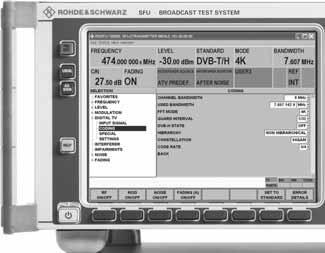
19 Digital modulation systems Terrestrial standards DVB-T/H (R&S SFU-K1 option) DVB-T/H in line with EN /EN Modulation COFDM bandwidth 5 MHz, 6 MHz, 7 MHz, 8 MHz (settable for variable bandwidth: 1 MHz to 10 MHz) MER >40 db 6 modulation frequency response <±0.2 db shoulder attenuation >48 db Coding constellation QPSK, 16QAM, 64QAM, hierarchical coding code rate 1/2, 2/3, 3/4, 5/6, 7/8 guard interval 1/4, 1/8, 1/16, 1/32 FFT 2k, 4k, and 8k COFDM interleaver native and in-depth TPS in line with DVB-T/H carrier modification carriers and carrier groups can be switched off Special functions Test signals scrambler, sync byte inversion, Reed-Solomon encoder, convolutional interleaver, bit interleaver, symbol interleaver, guard interval can be switched off TS test packet (see "Internal test signals") PRBS before convolutional encoder PRBS after convolutional encoder PRBS before mapper T-DMB/DAB (R&S SFU-K11 option) T-DMB/DAB in line with T-DMB/EN Korea/Europe Transmission modulation COFDM I, II, III, IV bandwidth MHz modulation frequency response <0.2 db shoulder attenuation >45 db Single-frequency network network MFN control MID, manual Special functions external ETI data stream requires R&S SFU-B11 option PRBS can be inserted into a subchannel 7 Gaussian fading profiles included; requires R&S SFU-B30 option 6 With internal test signals. 7 Can be inserted into an existing, user-selectable subchannel of an incoming, valid ETI data stream. Version 07.00, October 2008 R&S SFU Broadcast Test System 19
20 DMB-T (TDS-OFDM, R&S SFU-K7 option) (see ordering information) DMB-T (TDS-OFDM) in line with TDS-OFDM field trials in China Modulation COFDM bandwidth 6 MHz, 7 MHz, 8 MHz (settable for variable bandwidth: 5.6 MHz to MHz) modulation frequency response <0.2 db shoulder attenuation >50 db Coding constellation QPSK, 16QAM, 64QAM code rate 4/9, 2/3, 8/9 guard interval 420, 945 time interleaver 48, 240, 720 FFT 4k COFDM Special functions byte interleaver, randomizer, sync word randomizer, pilot data, guard interval, power boost can be switched off randomizer restart packet/frame Single-frequency network network MFN control MIP, manual Test signals TS test packet (see Internal test signals ) DTMB/DMB-TH (R&S SFU-K12 option) (see ordering information) DTMB (TDS-OFDM) in line with GB DMB-TH in line with LS specification field trials in China Modulation COFDM/single carrier bandwidth 6 MHz, 7 MHz, 8 MHz modulation frequency response <0.2 db shoulder attenuation >50 db Coding constellation 4QAM, 4QAM-NR, 16QAM, 32QAM, 64QAM code rate 0.4, 0.6, 0.8 guard interval PN sequences 420, 595, 945 PN sequences 420, 945 variable/constant PN sequence 595 constant time interleaver off, 240, 720 symbols FFT 4k COFDM/single carrier pilot carrier can be switched off (single carrier) Special functions GI power boost can be switched off guard interval PN can be switched over, variable, constant LDPC output I first, Q first, can be switched over, plus, minus QAM and QPSK constellation can be switched over DMB-TH can be switched on Single-frequency network network MFN, SFN control MIP, manual Test signals TS test packet (see "Internal test signals") 20 R&S SFU Broadcast Test System Version 07.00, October 2008
21 CMMB (R&S SFU-K15 option) (see ordering information) 8 CMMB in line with GY/T Modulation modulation COFDM bandwidth 2 MHz, 8 MHz modulation frequency response <0,2 db shoulder attenuation >50 db Coding FFT 1K, 4K scrambling 0 to 7 number of timeslots 40 services Reed Solomon (240,240) (240,224) (240,192) (240,176) byte interleaver 1 to 3 LDPC 1/2, 3/4 constellation BPSK, QPSK, 16QAM Special functions Reed Solomon, byte interleaver, bit interleaver, scrambling can be switched off ISDB-T/ ISDB-T B /ISDB-T SB (R&S SFU-K6 option) ISDB-T in line with ARIB STD-B31 version 1.7 ISDB-T B in line with Brazilian standard ISDB-T SB in line with ARIB STD-B29 Modulation OFDM bandwidth 6 MHz (variable: ±1000 ppm) number of segments ARIB STD-B31 13 ARIB STD-B29 1, 3 MER >40 db modulation frequency response <0.2 db shoulder attenuation >48 db Coding FFT 2k, 4k, and 8k number of layers 1 to 3 constellation QPSK, DQPSK, 16QAM, 64QAM code rate 1/2, 2/3, 3/4, 5/6, 7/8 guard interval 1/4, 1/8, 1/16, 1/32 time interleaver ISDB-T 0, 1, 2, 4, 8, 16 ISDB-T SB 0, 1, 2, 4, 8, 16, 32 Special functions scrambler, Reed-Solomon, byte interleaver, bit interleaver, frequency interleaver, guard interval, pilots, OFDM segments can be switched off AC information PRBS, all "1" Test signals TS test packet (see "Internal test signals") MediaFLO (R&S SFU-K10 option) (see ordering information) MediaFLO in line with QUALCOMM 80-T Modulation Rev. E COFDM bandwidth 5 MHz, 6 MHz, 7 MHz, 8 MHz modulation frequency response <0.2 db shoulder attenuation 50 db Coding FFT 4k COFDM Special function TDM1 can be switched off Test signals PRBS 8 In preparation; data preliminary. Version 07.00, October 2008 R&S SFU Broadcast Test System 21
22 ATSC 8VSB (R&S SFU-K4 option) ATSC 8VSB in line with ATSC Doc. A/53 (8VSB) Modulation 8VSB bandwidth 6 MHz symbol rate Msps range ±5 % settable pilot 1.25 (can be switched off) range settable (from 0 to 5 in steps of 0.001) pulse filtering root raised cosine roll-off, = MER >40 db 9 modulation frequency response <±0.25 db shoulder attenuation >45 db Coding input data rate Mbit/s Special functions randomizer, interleaver can be switched off Test signals TS test packet (see "Internal test signals") PRBS before convolutional encoder PRBS after convolutional encoder PRBS before mapper ATSC-M/H (R&S SFU-K18 option) (see ordering information) 10 ATSC-M/H in line with ATSC mobile TV USA ATSC/A-VSB (R&S SFU-K14 option) ATSC/A-VSB in line with ATSC mobile TV USA field trials Modulation 8VSB bandwidth 6 MHz symbol rate Msps range ±5 % settable pilot 1.25 (can be switched off) range settable (from 0 to 5 in steps of 0.001) pulse filtering root raised cosine roll-off, = MER >40 db modulation frequency response <±0.25 db shoulder attenuation >45 db Coding input data rate Mbit/s range ±5 % (depending on symbol rate) SRS s 0 to 4 turbo stream s 0 to 8 Special functions randomizer, interleaver can be switched off Test signals TS test packet (see "Internal test signals") PRBS before convolutional encoder PRBS after convolutional encoder PRBS before mapper 9 With internal test signals. 10 In preparation; data preliminary. 22 R&S SFU Broadcast Test System Version 07.00, October 2008
23 Cable standards DVB-C/ISDB-C (R&S SFU-K2 option) DVB-C ISDB-C Modulation Special functions Test signals in line with EN (ITU-T J.83/A) in line with ITU-T J.83/C 16QAM, 32QAM, 64QAM, 128QAM, 256QAM symbol rate 0.1 Msps to 8 Msps, settable pulse filtering root raised cosine roll-off, = 0.15, variable roll-off (0.1; 0.13; 0.15; 0.18; 0.20) MER >40 db modulation frequency response ±0.25 db shoulder attenuation >48 db energy dispersal, Reed-Solomon encoder (204, 188, t = 8), convolutional interleaver can be switched off TS test packet (see Internal test signals ) PRBS before mapper J.83/B (R&S SFU-K5 option) J.83/B Modulation Coding Special functions Test signals in line with ITU-T J.83/B 64QAM, 256QAM, 1024QAM bandwidth 6 MHz symbol rate 64QAM Msps 256QAM Msps 1024QAM Msps pulse filtering root raised cosine roll-off, = 0.18 (64QAM), 0.12 (256QAM/1024QAM) MER >40 db modulation frequency response ±0.25 db shoulder attenuation 64QAM >50 db 256QAM >45 db 1024QAM >45 db input data rate 64QAM Mbit/s 256QAM Mbit/s 1024QAM Mbit/s data interleaver can be switched off, level 1 and level 2 randomizer, Reed-Solomon encoder, interleaver, checksum can be switched off TS test packet (see "Internal test signals") PRBS before Trellis encoder PRBS before mapper Version 07.00, October 2008 R&S SFU Broadcast Test System 23
24 Satellite standards DVB-S/DVB-DSNG (R&S SFU-K3 option) DVB-S/DVB-DSNG in line with EN /EN Modulation QPSK, 8PSK, 16QAM symbol rate 0.1 Msps to 45 Msps, settable overrange >45 Msps to 66 Msps pulse filtering root raised cosine roll-off, = 0.35, variable roll-off (0.25; 0.30; 0.35; 0.40; 0.45) MER 38 db (27.5 Msps) modulation frequency response ±0.25 db shoulder attenuation >45 db Coding code rate QPSK: 1/2, 2/3, 3/4, 5/6, 7/8 8PSK: 2/3, 5/6, 8/9 16QAM: 3/4, 7/8 Special functions Test signals energy dispersal, Reed-Solomon encoder (204, 188, t = 8), convolutional interleaver can be switched off TS test packet (see Internal test signals ) PRBS before convolutional encoder DVB-S2 (R&S SFU-K8 option) (see ordering information) DVB-S2 in line with EN , broadcast services Modulation QPSK, 8PSK, 16APSK, 32APSK symbol rate QPSK, 8PSK 1 Msps to 40 Msps (overrange 45 Msps) 16APSK 2 Msps to 39 Msps 32APSK 2 Msps to 32 Msps pulse filtering root raised cosine roll-off, = 0.20, variable roll-off (0.15, 0.20, 0.25, 0.35) MER 38 db (20 Msps) modulation frequency response ±0.25 db shoulder attenuation 45 db Coding code rate QPSK 1/4, 1/3, 2/5, 1/2, 3/5, 2/3, 3/4, 4/5, 5/6, 8/9, 9/10 8PSK 3/5, 2/3, 3/4, 5/6, 8/9, 9/10 16APSK 2/3, 3/4, 4/5, 5/6, 8/9, 9/10 32APSK 3/4, 4/5, 5/6, 8/9, 9/10 FEC frame normal, bit; short, bit pilot insertion can be switched off Special function error insertion after CRC-8, BCH or LDPC Test signals TS test packet (see Internal test signals ) DIRECTV legacy modulation (R&S SFU-K9 option) (see ordering information) DIRECTV legacy modulation in line with DIRECTV transmission Modulation specifications QPSK symbol rate 20 Msps overrange 1 Msps to 30 Msps pulse filtering root raised cosine roll-off, = 0.20, variable roll-off (0.15, 0.20, 0.25, 0.35) MER 38 db (20 Msps) modulation frequency response <±0.25 db shoulder attenuation 45 db Coding code rate 1/2, 2/3, 6/7 Special function customer-specific DIRECTV streams can be replayed in 188-byte format, requires R&S SFU-K21, R&S SFU-K22 option error insertion after convolutional encoder Test signals TS test packet (see "Internal test signals") 24 R&S SFU Broadcast Test System Version 07.00, October 2008
25 AMC (R&S SFU-K108 option) (see ordering information) AMC (advanced modulation coding) in line with AMC supports DIRECTV as well as parts of DVB-S and phase noise Modulation QPSK, H8PSK symbol rate DVB-S: 1 Msps to 36 Msps (and up to 42 Msps depending on code rate) DIRECTV: 20 Msps overrange for DIRECTV 1 Msps to 30 Msps pulse filtering root raised cosine roll-off, = 0.20, variable roll-off (0.15, 0.20, 0.25, 0.35) MER 38 db (20 Msps) modulation frequency response <±0.25 db shoulder attenuation 45 db Coding constellation QPSK code rate DIRECTV: 1/2, 2/3, 6/7 DVB-S: 1/2, 2/3, 3/4, 5/6, 7/8 Special function phase noise can be switched on Version 07.00, October 2008 R&S SFU Broadcast Test System 25
26 Analog modulation systems AM/FM/RDS (R&S SFU-K170 option) (see ordering information) FM FM operating s audio signals stereo, mono FM stereo internal audio signal generator external audio input AF frequency range AF frequency response attenuation at 19 khz preemphasis residual AM stereo operating s MPX frequency deviation deviation stereo crosstalk attenuation total harmonic distortion SNR (stereo/rds signal) 11 ITU-R weighted (quasi-peak) ITU-R unweighted (rms) pilot tone see audio generator see analog audio input 30 Hz to 15 khz <0.2 db >70 db OFF, 50 μs, 75 μs <0.1 % (at AF = 1 khz, deviation ±50 khz) L, R, L=R, L=-R, L R internal RDS signal generation, MPX and RDS signals can be generated simultaneously 0 Hz to ±100 khz 10 Hz >50 db (at AF = 30 Hz to 15 khz) <0.1 % (at 60 khz audio frequency deviation, AF = 1 khz) at audio frequency deviation ±40 khz >64 db >70 db frequency 19 khz ± 1 Hz deviation 0 Hz to ±15 khz 10 Hz phase 0º to ±180º 0,1º RDS FM mono AM subcarrier frequency deviation mono frequency deviation deviation total harmonic distortion 12 audio signals internal audio signal generator external audio input AF frequency range AF frequency response attenuation at 3.15 khz modulation 57 khz ±3 Hz 0 Hz to ±10 khz 10 Hz 0 Hz to ±100 khz 10 Hz <0.1 % (at ±67.5 khz audio frequency deviation, AF = 1 khz) see audio generator 30 Hz to 2.25 khz <0.2 db >35 db modulation depth 0 % to 100 % 1 % AM total harmonic distortion at AF = 1 khz m = 30 % <0.2 % m = 80 % <0.2 % 11 Generator without preemphasis, receiver with deemphasis. 12 Generator and receiver without preemphasis/deemphasis. 26 R&S SFU Broadcast Test System Version 07.00, October 2008
27 Standard B/G (R&S SFU-K190 option) (see ordering information) Standard B/G in line with country-specific standard Vision modulation modulation B/G group delay precorrection CCIR B/G Germany general half (can be switched off) frequency response <20 ns (with/without vestigial sideband filtering) vestigial sideband filtering B/G, can be switched off amplitude frequency response <0.5 db ( 0.6 MHz to +4.8 MHz) (with/without vestigial sideband filtering) S/N ratio video >60 db weighted Sound modulation mono, stereo, dual sound, mono/nicam, NICAM modulation of sound carrier 1, 2 modulation FM frequency deviation 30 khz (settable) preemphasis 50 μs/75 μs (can be switched off) vision/sound carrier frequency spacing 5.5 MHz/5.74 MHz (settable) vision/sound carrier level spacing 13 db/20 db (settable) pilot tone in sound carrier 2 (can be switched off) S/N ratio sound >60 db weighted (CCIR) Video signals internal video generator see R&S SFU-K23 option external video input see video input Audio signals internal audio generator see audio generator external audio input see audio input Standard D/K (R&S SFU-K191 option) (see ordering information) Standard D/K Vision modulation Sound modulation Video signals Audio signals in line with country-specific standard modulation group delay precorrection frequency response vestigial sideband filtering amplitude frequency response S/N ratio video modulation of sound carrier 1, 2 modulation frequency deviation preemphasis vision/sound carrier frequency spacing vision/sound carrier level spacing pilot tone S/N ratio sound internal video generator external video input internal audio generator external audio input D/K OIRT D/K half (can be switched off) <20 ns (with/without vestigial sideband filtering) DK, DK FM2, DK NICAM, can be switched off <0.5 db ( 1 MHz to +5.8 MHz) (with/without vestigial sideband filtering) >60 db weighted mono, stereo, dual sound, NICAM, mono/nicam FM 30 khz (settable) 50 μs/75 μs (can be switched off) 6.5 MHz/6.74 MHz (settable) 13 db/20 db (settable) in sound carrier 2 (can be switched off) >60 db weighted (CCIR) see R&S SFU-K23 option see video input see audio generator see audio input Version 07.00, October 2008 R&S SFU Broadcast Test System 27
28 Standard I (R&S SFU-K192 option) (see ordering information) Standard I in line with country-specific standard Vision modulation modulation group delay precorrection frequency response vestigial sideband filtering amplitude frequency response S/N ratio video Sound modulation modulation of sound carrier 1 modulation frequency deviation preemphasis vision/sound carrier frequency spacing vision/sound carrier level spacing modulation of sound carrier 2 modulation vision/sound carrier frequency spacing vision/sound carrier level spacing S/N ratio sound Video signals internal video generator external video input Audio signals internal audio generator external audio input Standard M/N (R&S SFU-K193 option) (see ordering information) Standard M/N in line with country-specific standard Vision modulation modulation group delay precorrection frequency response vestigial sideband filtering amplitude frequency response S/N ratio video Sound modulation modulation of sound carrier 1, 2 modulation frequency deviation preemphasis vision/sound carrier frequency spacing vision/sound carrier level spacing pilot S/N ratio sound Video signals internal video generator external video input Audio signals internal audio generator external audio input I UK I (can be switched off) <20 ns (with/without vestigial sideband filtering) I, I1, can be switched off <0.5 db ( 1 MHz to +4.8 MHz) (with/without vestigial sideband filtering) >60 db weighted mono, mono/nicam, NICAM FM 30 khz (settable) 50 μs/75 μs (can be switched off) 6 MHz (settable) 13 db (settable) NICAM MHz (settable) 20 db (settable) >60 db weighted (CCIR) see R&S SFU-K23 option see video input see audio generator see audio input M/N FCC M/N (can be switched off) <20 ns (with/without vestigial sideband filtering) M, N, can be switched off <0.5 db ( 0.6 MHz to +4 MHz) (with/without vestigial sideband filtering) >60 db weighted BTSC mono, stereo Korea, dual sound Korea FM 25 khz (settable) 50 μs/75 μs (can be switched off) 4,5 MHz/4,742 MHz (settable) 13 db/20 db (settable) in sound carrier 2 (can be switched off) >60 db weighted (CCIR) see R&S SFU-K23 option see video input see audio generator see audio input 28 R&S SFU Broadcast Test System Version 07.00, October 2008
29 Standard L (R&S SFU-K194 option) (see ordering information) Standard L in line with country-specific standard Vision modulation modulation group delay precorrection frequency response vestigial sideband filtering amplitude frequency response Sound modulation modulation of sound carrier 1 modulation vision/sound carrier frequency spacing vision/sound carrier level spacing modulation of sound carrier 2 modulation frequency deviation vision/sound carrier frequency spacing vision/sound carrier level spacing Video signals internal video generator external video input Audio signals internal audio generator external audio input L TDF - L (can be switched off) <20 ns (with/without vestigial sideband filtering) L, L NICAM, can be switched off <0.5 db ( 1 MHz to +5.8 MHz) (with/without vestigial sideband filtering) AM mono, mono/nicam, NICAM NICAM 5.85 MHz (settable) 27 db (settable) AM modulation depth 54 % (settable) 6.5 MHz (settable) 10 db (settable) see R&S SFU-K23 option see video input see audio generator see audio input Multi ATV predefined (R&S SFU-K199 option) (see ordering information) Multi ATV predefined Modulation Standard PAL B/G Standard PAL B/G + NICAM Standard PAL I in line with country-specific standards and MBRAI standards B/G, B/G N, I, I1, D/K, D1, M/N, L signals one defined ATV signal per standard implementation in line with MBRAI PAL B/G with A2 video test signal PAL B/G color bar 75 % insertion test signal structure see below sound subcarrier sound 1 FM 50 khz deviation/5.5 MHz/13 db sound 2 FM 50 khz deviation/5.742 MHz/20 db audio coding stereo left 1 khz right 1 khz group delay precorrection CCIR B/G Germany residual carrier 10 % implementation in line with MBRAI PAL B/G with NICAM video test signal PAL B/G color bar 75 % insertion test signal structure see below sound subcarrier sound 1 FM 50 khz deviation/5.5 MHz/13 db sound 2 NICAM 13 roll-off = 40 %/5.85 MHz/20 db audio coding mono sound 1 1 khz group delay precorrection CCIR B/G Germany residual carrier 10 % video test signal PAL I color bar 75 % insertion test signal structure see below sound subcarrier sound 1 FM 50 khz deviation/6.0 MHz/13 db sound 2 NICAM 13 roll-off = 100 %/6,552 MHz /20 db audio coding mono sound 1 1 khz group delay precorrection none residual carrier 20 % 13 Simulation of NICAM spectrum by means of PN sequence and appropriate pulse shaping. Version 07.00, October 2008 R&S SFU Broadcast Test System 29
30 Standard PAL I1 Standard PAL D/K Standard PAL D1 Standard M/N Standard SECAM L implementation in line with MBRAI PAL-I1 video test signal PAL I1 color bar 75 % insertion test signal structure see below sound subcarrier sound 1 FM 50 khz deviation /6.0 MHz/13 db sound 2 NICAM 14 roll-off = 100 %/6.552 MHz /20 db audio coding mono sound 1 1 khz group delay precorrection none residual carrier 20 % video test signal PAL D/K FuBK insertion test signal structure see below sound subcarrier sound 1 FM 50 khz deviation/6.5 MHz/13 db sound 2 FM 50 khz deviation/6.74 MHz/20 db audio coding stereo left 1 khz right 1 khz group delay precorrection flat residual carrier 12.5 % implementation in line with MBRAI PAL-D1 video test signal PAL D1 color bar 75 % insertion test signal structure see below sound subcarrier sound 1 FM 50 khz deviation /6.5 MHz/13 db sound 2 NICAM 14 roll-off = 40 %/5.85 MHz /20 db audio coding mono sound 1 1 khz group delay precorrection half, OIRT residual carrier 12.5 % video test signal NTSC M SMPTE color bar with PLUGE insertion test signal structure see below sound subcarrier FM 50 khz deviation /4.5 MHz/7 db audio coding mono sound Hz group delay precorrection 5 MHz/FCC residual carrier 12.5 % implementation in line with MBRAI SECAM L video test signal SECAM L color bar 75 % insertion test signal structure see below sound subcarrier sound 1 NICAM 14 roll-off = 40 %/5.85 MHz/27 db sound 2 AM modulation depth = 54 %/6.5 MHz/10 db audio coding sound 1 mono sound 2 1 khz group delay precorrection full, TDF residual carrier 3 % 14 Simulation of NICAM spectrum by means of PN sequence and appropriate pulse shaping. 30 R&S SFU Broadcast Test System Version 07.00, October 2008
31 Insertion test signal structure in line with country-specific standards Standards B/G,B/G N, I, I1, D/K, D1 and standard IEC with first field lines 8, 10 2T pulse 2 CH. PAL B (MBRAI) line 16 data line 1 2 CH. PAL G (MBRAI) lines 17, 18 CCIR17 2 CH. PAL B N (MBRAI) line 19 CCIR18/2 2 CH. PAL G N (MBRAI) lines 20, 21 teletext test line 2 CH. PAL I1 (MBRAI) 2 CH. PAL D1 (MBRAI) second field line 323 teletext test line DVB-T + PAL B (MBRAI) line 329 data line 2 DVB-T + PAL G (MBRAI) lines 330, 331 CCIR330/5 DVB-T + PAL B N (MBRAI) line 332 CCIR331/1 DVB-T + PAL G N (MBRAI) line 333 sinx/x DVB-T + PAL I1 (MBRAI) lines 334, 335 teletext test line DVB-T + PAL D1 (MBRAI) Standard M/N first field line 17 NTC7 composite line 18 FCC composite second field line 17 NTC7 combined line 18 sinx/x Standard L and standard IEC with first field lines 7 to 14 discriminating signal DVB-T + SECAM L (MBRAI), line 15 teletext test line 2 CH. SECAM L (MBRAI) line 17 CCIR17 line 18 CCIR18, 6 multiburst packets second field lines 320 to 328 discriminating signal line 330 CCIR330 lines 331, 332 CCIR331 line 333 CCIR331/1 MBRAI signal combinations Signal combinations in line with IEC (MBRAI) Digital/analog multi-interferer pattern L1 digital N+2/analog N+4 signal DVB-T + PAL B (MBRAI) DVB-T + PAL G (MBRAI) DVB-T + PAL B N (MBRAI) DVB-T + PAL G N (MBRAI) DVB-T + PAL I1 (MBRAI) DVB-T + PAL D1 (MBRAI) DVB-T + SECAM L (MBRAI) Analog multi-interferer pattern L2 2 analog N+2/N+4 signals 2 CH. PAL B (MBRAI) 2 CH. PAL G (MBRAI) 2 CH. PAL B N (MBRAI) 2 CH. PAL G N (MBRAI) 2 CH. PAL I1 (MBRAI) 2 CH. PAL D1 (MBRAI) 2 CH. SECAM L (MBRAI) Version 07.00, October 2008 R&S SFU Broadcast Test System 31
32 Simulation Arbitrary waveform generator (R&S SFU-K35 option) (see ordering information) Waveform memory length 512 sample to 128 Msample in one-sample steps 16 bit loading time for 10 Msample 3 s nonvolatile memory hard disk Clock generation clock rate 400 Hz to 100 MHz accuracy Hz operating internal frequency accuracy (internal) accuracy of reference frequency Interpolation bandwidth with clock rate = 100 MHz (no interpolation), bandwidth 0.1 db 40 MHz with clock rate <100 MHz, bandwidth 0.1 db 0.31 clock rate sampling rate automatically interpolated to the internal 100 MHz data rate Trigger operating auto, retrigger, armed auto, armed retrigger source internal, external delay settable from 0 to samples inhibit settable from 0 to samples Marker position restart waveform delay settable from 0 to waveform length in samples Special function software support R&S WinIQSIM 15 R&S SMU-K15 custom OFDM 15 With R&S WinIQSIM TM : Software version 4.24 or later supports the download of I/Q data and the control of the R&S SFU-K R&S SFU Broadcast Test System Version 07.00, October 2008
33 T-DMB/DAB waveforms (R&S SFU-K351 option) T-DMB/DAB waveforms I/Q sequences with audio and video contents for details see description of option Transmission modulation I, II Signal set video CIF ( ), QCIF ( ), QVGA ( ) sequences diver, fishes audio background music audio program service signal 1 khz sinewave level 0 dbfs sampling rate 48 khz stereo data rate 192 kbit/s Special function Gaussian fading profiles included, can be used with R&S SFU-B30 option DVB-H waveforms (R&S SFU-K352 option) DVB-H waveforms I/Q sequences with audio and video contents for details see description of option Transmission different DVB-H s Signal set video/audio different s and sequences DRM waveforms (R&S SFU-K353 option) DRM waveforms I/Q sequences with audio contents for details see description of option Transmission A, B, C, and D constellation 4QAM, 16QAM, and 64QAM (OFDM) bandwidth 4.5 khz, 5 khz, 9 khz, 10 khz, 18 khz, 20 khz sampling rate 12 khz, 48 khz Signal set audio signal different sequences level 10 dbfs, 12 dbfs mono coding MPEG-4 AAC, MPEG-4 CELP data rate 4.8 kbit/s to 30.6 kbit/s DTV interferers (R&S SFU-K354 option) DTV interferers I/Q sequences in line with country-specific standards, IEC MBRAI, NORDIG, Dbook, A.74 for details see description of option Waveforms length 512 sample to 128 Msample 16 bit loading time for 64 Msample 20 s nonvolatile memory hard disk Signal set standards DVB-T, ATSC/8VSB, T-DMB/DAB, MediaFLO, ISDB-T, ISDB-T SB, FM DVB-T standard length superframe single-interferer sequence bandwidth 5 MHz, 6 MHz, 7 MHz, 8 MHz FFT 8k constellation 16QAM code rate 2/3 guard interval 1/8 multi-interferer sequence pattern pattern L3 (2 DVB-T signals N+2/N+4) bandwidth 8 MHz FFT 8k constellation 16QAM code rate 2/3 guard interval 1/8 Version 07.00, October 2008 R&S SFU Broadcast Test System 33
34 ATSC/8VSB standard Standard MediaFLO Standard DTMB (GB ) T-DMB/DAB standard Standard ISDB-T Standard ISDB-T SB Standard FM length sequences length bandwidth length bandwidth constellation length bandwidth single-interferer sequence multi-interferer sequence two channels three channels 1 data frame center frequency, pilot frequency 1 s 6 MHz 1 s single carrier/multicarrier 8 MHz 4QAM, 16QAM, 32QAM, 64QAM/16QAM frame I 8 MHz center frequency A, D, with frequency gap B, C A, C, with frequency gap B, D with frequency offset MHz A, B, with frequency gap C, D, with frequency offset MHz A, B, C, with frequency offset MHz A, C, D, with frequency gap B A, B, D, with frequency gap C A, B, C, D approx. 231 ms four channels length single-interferer sequence OFDM segments 1, 3 length approx. 202 ms, 231 ms single-interferer sequence OFDM segments 1, 3 length frame single-interferer sequence FM jammer infinite seamless frequency 1 khz frequency deviation ±50 khz (in line with GSM900 TX) MediaFLO waveforms (R&S SFU-K355 option) MediaFLO waveforms I/Q sequences in line with MediaFLO for details see description of option Transmission content data length 6 superframes, 6 seconds bandwidth 6 MHz Signal set wide area ID 15 local area ID 10 and 15 data several MediaFLO IDs with different TX s depending on sequence 34 R&S SFU Broadcast Test System Version 07.00, October 2008
SFU Broadcast Test System
 Version 06.00 SFU Broadcast Test System August 2007 Data sheet CONTENTS INTRODUCTION...4 APPLICATIONS OVERVIEW...4 KEY FEATURES...5 General...5 Intuitive, fast and easy operation...5 Outstanding signal
Signal Generator SMA 100A
 Specifications Version 01.01 Signal Generator SMA 100A April 2006 Specifications CONTENTS CONTENTS... 2 KEY FEATURES... 3 SPECIFICATIONS... 4 RF CHARACTERISTICS... 4 Frequency... 4 Frequency sweep... 4
TV Test Transmitter SFM
 Data sheet supplied by: Text in Weiß TV Test Transmitter SFM The multistandard platform for tomorrow s TV The TV Test Transmitter SFM supplies vision and sound signals for all presently used TV standards.
R&S CLGD-K2 Basic Waveform Library Manual
 R&S CLGD-K2 Basic Waveform Library Manual 2118.7475.02 02 Broadcast and Media Manual PAD-T-M: 3574.3259.02/01.00/CI/1/EN The Manual describes the content of the basic waveform library: R&S CLGD-K2 2118.7469.02
R&S SMW200A Vector Signal Generator Specifications
 SMW200A_dat-sw_en_3606-8037-22_v0302_cover.indd 1 Data Sheet 03.02 Test & Measurement R&S SMW200A Vector Signal Generator Specifications 19.03.2015 09:39:58 CONTENTS Key features... 4 Definitions... 5
MEX II. Multimode TV Exciter HE ANALOG / DIGITAL
 ANALOG / DIGITAL Multimode TV Exciter Fully numerical signal elaboration and modulation Adaptive pre-distorter and pre-equalizer Multi-Standard equipment Dual Cast transmitter Band I Band III Band IV/V
R&S ETL TV Analyzer Specifications
 R&S ETL TV Analyzer Specifications Broadcast Test & Measurement Data Sheet 09.00 CONTENTS Specifications... 4 Part 1 TV analyzer... 4 Frequency...4 Level...4 Analog TV standards and options...5 R&S ETL-K202
VENTUS 1.0 All in One USB Type of DTV / Mobile TV Signal Generator
 to be Better or to be Different LUMANTEK VENTUS 10 All in One USB Type of DTV / Mobile TV Signal Generator ATSC-Mobile CMMB DTMB DVB-T/H DVB-C OpenCable ATSC T-DMB / DAB+ ISDB-T Mobility + Upgradable Design
R&S SMW200A Vector Signal Generator Specifications
 R&S SMW200A Vector Signal Generator Specifications year Data Sheet Version 04.04 CONTENTS Key features... 4 Definitions... 5 Frequency and baseband main module options... 6 Frequency options... 6 Signal
R&S SMB100N SIGNAL GENERATOR
 R&S SMB100N SIGNAL GENERATOR PERFORMANCE SPECIFICATIONS VERSION 02.00, SEPTEMBER 2009 CONTENTS Specifications...3 Definitions... 3 RF performance... 4 Frequency... 4 Frequency sweep... 4 Reference frequency...
R&S ETL TV Analyzer Specifications
 R&S ETL TV Analyzer Specifications Broadcasting Test & Measurement Data Sheet 11.00 CONTENTS Definitions... 4 Part 1 TV analyzer... 5 Frequency...5 Level...5 Analog TV standards and options...6 R&S ETL-K202
Chapter 6 Specifications
 RIGOL This chapter describes the specifications of RF signal generator. Specifications are valid under the following conditions: the instrument in the calibration cycle is stored at least two hours at
R&S ETL TV Analyzer Specifications
 ETL_dat-sw_en_5213-7748-22_Cover.indd 1 Data Sheet 15.00 Broadcasting Test & Measurement R&S ETL TV Analyzer Specifications 14.03.2013 19:35:01 CONTENTS Definitions... 5 Part 1 TV analyzer... 6 Frequency...
DTA-2115 All-Standard, All-Band Modulator
 DTA-2115 Dystrybucja: elmier.pl All-Standard, All-Band Modulator DATASHEET Feb 2015 elmier@elmier.pl +48 500 167 343 Table of Contents 1. Introduction... 3 General Description... 3 Block Diagram... 3 Software
R&S SMW200A Vector Signal Generator Specifications
 R&S SMW200A Vector Signal Generator Specifications year Data Sheet Version 07.00 CONTENTS Key features... 5 Definitions... 6 Frequency and baseband main module options... 7 Frequency options... 7 Signal
RECOMMENDATION ITU-R BT Error-correction, data framing, modulation and emission methods for digital terrestrial television broadcasting
 Rec. ITU-R BT.1306-3 1 RECOMMENDATION ITU-R BT.1306-3 Error-correction, data framing, modulation and emission methods for digital terrestrial television broadcasting (Question ITU-R 31/6) (1997-2000-2005-2006)
MG3740A Analog Signal Generator. 100 khz to 2.7 GHz 100 khz to 4.0 GHz 100 khz to 6.0 GHz
 Data Sheet MG3740A Analog Signal Generator 100 khz to 2.7 GHz 100 khz to 4.0 GHz 100 khz to 6.0 GHz Contents Definitions, Conditions of Specifications... 3 Frequency... 4 Output Level... 5 ATT Hold...
Vector Signal Generators
 Vector Signal Generators SG390 Series DC to 2 GHz, 4 GHz and 6 GHz vector signal generators SG390 Series Vector Signal Generators DC to 2 GHz, 4 GHz or 6 GHz Dual baseband arb generators Vector and analog
Systems for Audio and Video Broadcasting (part 2 of 2)
") Systems for Audio and Video Broadcasting (part 2 of 2) Ing. Karel Ulovec, Ph.D. CTU in Prague, Faculty of Electrical Engineering xulovec@fel.cvut.cz Only for study purposes for students of the! 1/30 Systems
Systems for Audio and Video Broadcasting (part 2 of 2) Ing. Karel Ulovec, Ph.D. CTU in Prague, Faculty of Electrical Engineering xulovec@fel.cvut.cz Only for study purposes for students of the! 1/30 Systems
120W UHF Transmitter/Repeater
 Product Features 470 MHz - 860 MHz Broadband Transmitter/Repeater LDMOS Power Amplifier provides 120 Watt output for ATSC, ATSC-M/H, CMMB, DTMB, DVB-T/H, DVB-T2, DVB-SH, ISDB-T/TB,, DAB, DAB+ and T-DMB
SMU200A Vector Signal Generator
 Version 07.00 SMU200A Vector Signal Generator December 2007 Data sheet CONTENTS Introduction...4 Key features...5 Frequency and enhancement options...6 Frequency options...6 Enhancement options...6 Modulation...6
Vector Signal Generators
 Vector Signal Generators SG390 Series DC to 2 GHz, 4 GHz and 6 GHz vector signal generators SG390 Series Vector Signal Generators DC to 2 GHz, 4 GHz or 6 GHz Dual baseband arb generators Vector and analog
SIGNAL GENERATORS. MG3633A 10 khz to 2700 MHz SYNTHESIZED SIGNAL GENERATOR GPIB
 SYNTHESIZED SIGNAL GENERATOR MG3633A GPIB For Evaluating of Quasi-Microwaves and Measuring High-Performance Receivers The MG3633A has excellent resolution, switching speed, signal purity, and a high output
Signal Generator SMA100A
 Specifications Version 02.01 Signal Generator SMA100A November 2006 Specifications CONTENTS KEY FEATURES... 3 SPECIFICATIONS... 4 RF CHARACTERISTICS... 4 Frequency... 4 Frequency sweep... 4 Reference frequency...
MOBILE COMMUNICATIONS MEASURING INSTRUMENTS
 DIGITAL MODULATION SIGNAL GENERATOR MG3681A 250 khz to 3 GHz GPIB For Evaluating Next Generation Digital Mobile Communications Systems The MG3681A uses a wideband vector modulator to output the highaccuracy,
R&S CMW100 Communications Manufacturing Test Set Specifications
 R&S CMW100 Communications Manufacturing Test Set Specifications Data Sheet Version 02.00 CONTENTS Definitions... 6 General technical specifications... 7 RF generator... 8 Modulation source: arbitrary waveform
SMA100A Signal Generator
 Version 02.02 SMA100A Signal Generator August 2007 Data sheet CONTENTS KEY FEATURES...3 SPECIFICATIONS...4 RF CHARACTERISTICS...4 Frequency...4 Frequency sweep...4 Reference frequency...4 Level...5 Level
R&S CMW100 Communications Manufacturing Test Set Specifications
 R&S CMW100 Communications Manufacturing Test Set Specifications R&S CMW100 model.k06 Data Sheet Version 03.00 CONTENTS Definitions... 4 General technical specifications... 5 RF generator... 6 RF analyzer...
DTVM 2000(T) Digital Terrestrial Television Transmitter Monitor
 Digital Terrestrial Television Transmitter Monitor") DTVM 2000(T) Digital Terrestrial Television Transmitter Monitor The DTVM 2000(T) Digital Terrestrial Television Transmitter Monitor range has been designed for DVB signal quality measurement applications.
DTVM 2000(T) Digital Terrestrial Television Transmitter Monitor The DTVM 2000(T) Digital Terrestrial Television Transmitter Monitor range has been designed for DVB signal quality measurement applications.
Signal generators. Modular design for user-friendly solutions
 GENERAL PURPOSE 43985/1 FIG 1 Visionary: The new Vector Signal Generator R&S SMU200A offers two complete signal generators with digital modulation capability in a single instrument and facilitates the
Vector Signal Generator SMV03
 Data sheet Version 03.00 Vector Signal Generator SMV03 September 2004 Vector modulation in the analog class Frequency range 9 khz to 3.3 GHz I/Q modulator (100 MHz RF bandwidth) with excellent vector accuracy
Test Equipment Solutions Datasheet
 Test Equipment Solutions Datasheet Test Equipment Solutions Ltd specialise in the second user sale, rental and distribution of quality test & measurement (T&M) equipment. We stock all major equipment types
Maxiva UAXT Ultra-Compact/ VAXT Ultra-Compact Low Power UHF/VHF Transmitter / Transposer / Gap Filler
 Maxiva UAXT Ultra-Compact/ VAXT Ultra-Compact Low Power UHF/VHF Transmitter / Transposer / Gap Filler The new Maxiva UAXT & VAXT Ultra Compact family of UHF & VHF solid-state Transmitters, Transposers
R&S CMW500 Wideband Radio Communication Tester Specifications
 R&S CMW500 Wideband Radio Communication Tester Specifications Test & Measurement Data Sheet 06.00 CONTENTS General technical specifications... 6 RF generator...6 Modulation source: arbitrary waveform generator
R&S SMC100A Signal Generator Specifications
 R&S SMC100A Signal Generator Specifications Test & Measurement Data Sheet 01.00 CONTENTS Key features... 3 Specifications... 4 RF characteristics...4 Frequency...4 Frequency sweep...4 Reference frequency...4
Digital TV Rigs and Recipes Part 2 DVB-C
 Digital TV Rigs and Recipes Part 2 DVB-C S. Grunwald Graduate in Engineering Contents 2 Introduction... 3 2.1 DVB-C Modulation (Cable) to EN 300 429... 3 2.1.1 Baseband Input Module... 3 2.1.2 Sync Word
2026Q CDMA/GSM Interferer MultiSource Generator
 Signal Sources 2026Q CDMA/GSM Interferer MultiSource Generator The 2026Q is designed to work with a radio test set to provide a fully integrated radio receiver test solution for cellular and PCS systems
SIGNAL PROCESSING WIRELESS COMMUNICATION RF TEST AND MEASUREMENT AUTOMOTIVE DEFENSE AND AEROSPACE
 SIGNAL PROCESSING WIRELESS COMMUNICATION RF TEST AND MEASUREMENT AUTOMOTIVE DEFENSE AND AEROSPACE Your One-Stop Provider for In-Vehicle Infotainment (IVI Test), Set-Top-Box, Digital TV Mobile TV test solution.
Agilent E4428C ESG Analog Signal Generator
 Migrate to the new Agilent MXG X-Series signal generator and generate true performance The new MXG exceeds the ESG s performance in every category - output power, phase noise, spurious, and low frequency
UNIVERSITATEA POLITEHNICA BUCUREŞTI FACULTATEA DE ELECTRONICĂ, TELECOMUNICAŢII ŞI TEHNOLOGIA INFORMAȚIEI LABORATOR TELEVIZIUNE
 UNIVERSITATEA POLITEHNICA BUCUREŞTI FACULTATEA DE ELECTRONICĂ, TELECOMUNICAŢII ŞI TEHNOLOGIA INFORMAȚIEI LABORATOR TELEVIZIUNE VIDEO QUALITY MEASUREMENT IN DIGITAL TELEVISION SYSTEMS 1. DVB The Digital
RF Signal Generator SM300
 RF Signal Generator SM300 9 khz to 3 GHz With compliments Helmut Singer Elektronik www.helmut-singer.de info@helmut-singer.de fon +49 241 155 315 fax +49 241 152 066 Feldchen 16-24 D-52070 Aachen Germany
R&S SMW200A Vector Signal Generator Specifications
 www.atecorp.com 800-404-ATEC (2832) R&S SMW200A Vector Signal Generator Specifications SMW200A_dat-sw_en_3606-8037-22_v0102_cover.indd 1 Data Sheet 01.02 E stablished 1981 Advanced Test Equipment Rentals
Keysight Technologies E8257D PSG Microwave Analog Signal Generator. Data Sheet
 Keysight Technologies E8257D PSG Microwave Analog Signal Generator Data Sheet 02 Keysight E8257D Microwave Analog Signal Generator - Data Sheet Table of Contents Specifications... 4 Frequency... 4 Step
Chapter 5 Specifications
 RIGOL Specifications are valid under the following conditions: the instrument is within the calibration period, is stored for at least two hours at 0 to 50 temperature and is warmed up for 40 minutes.
Advanced Test Equipment Rentals ATEC (2832)
") Established 1981 Advanced Test Equipment Rentals www.atecorp.com 800-404-ATEC (2832) Data sheet Version 06.00 Signal Generator SML August 2004 Economy at its best 9 khz to 1.1 GHz/2.2 GHz/3.3 GHz SSB phase
Established 1981 Advanced Test Equipment Rentals www.atecorp.com 800-404-ATEC (2832) Data sheet Version 06.00 Signal Generator SML August 2004 Economy at its best 9 khz to 1.1 GHz/2.2 GHz/3.3 GHz SSB phase
TV Test Receiver EFA, Models 40/43 (DVB-T)
") TV Test Receiver EFA, Models 40/43 (DVB-T) Comprehensive analysis/demodulation/monitoring of digital terrestrial TV signals All DVB-T modes supported according to ETS300744 High-end demodulator High-end
TV Test Receiver EFA, Models 40/43 (DVB-T) Comprehensive analysis/demodulation/monitoring of digital terrestrial TV signals All DVB-T modes supported according to ETS300744 High-end demodulator High-end
Desire Innovation. >> Wireless Communication Test System FM / RDS / TMC GPS. Digital TV. Audio Generator / Analyzer GPS. RF Player FM / RDS / TMC
 Desire Innovation GPS RF Player FM / RDS / TMC Digital TV Audio Generator / Analyzer MP RF STATION 9000 2 11 >> Wireless Communication Test System GPS RF Player FM / RDS / TMC Digital TV Audio Generator
Signal Generator SMA100A
 Product brochure Version 02.01 Signal Generator SMA100A November 2006 The new standard of excellence in the analog signal generator class Excellent signal quality Ideal for use in production All-purpose
FREQUENCY SYNTHESIZERS, SIGNAL GENERATORS
 SYNTHESIZED SIGNAL GENERATOR MG3641A/MG3642A 12 khz to 1040/2080 MHz NEW New Anritsu synthesizer technology permits frequency to be set with a resolution of 0.01 Hz across the full frequency range. And
Signal Generator SML
 Signal Generator SML Economy at its best 9 khz to 1.1 GHz/2.2 GHz/3.3 GHz SSB phase noise: < 122 dbc (1 Hz) (at f = 1 GHz, f = 20 khz) Setting times
Generating Interference Signals Using the R&S SFU-K37 Option
 Products: R&S SFU Broadcast Test System Generating Interference Signals Using the R&S SFU-K37 Option Application Note This Application Note introduces the new interferer management option, R&S SFU-K37
Model 745 Series. Berkeley Nucleonics Test, Measurement and Nuclear Instrumentation since Model 845-HP Datasheet BNC
 Model 845-HP Datasheet Model 745 Series Portable 20+ GHz Microwave Signal Generator High Power +23dBM Power Output 250 fs Digital Delay Generator BNC Berkeley Nucleonics Test, Measurement and Nuclear Instrumentation
Vector Signal Generator SMU200A
 Specifications Version 02.00 Vector Signal Generator SMU200A June 2004 Specifications CONTENTS INTRODUCTION...3 KEY FEATURES...4 SPECIFICATIONS...5 FREQUENCY AND RF OPTIONS...5 Frequency options...5 RF
ArbStudio Arbitrary Waveform Generators
 ArbStudio Arbitrary Waveform Generators Key Features Outstanding performance with 16-bit, 1 GS/s sample rate and 2 Mpts/Ch 2 and 4 channel models Digital pattern generator PWM mode Sweep and burst modes
R&S ZVT Vector Network Analyzer Specifications
 R&S ZVT Vector Network Analyzer Specifications Test & Measurement Data Sheet 08.00 CONTENTS Definitions... 3 Specifications... 4 Measurement range...4 Measurement speed...5 Measurement accuracy...6 Effective
Getting Started Guide
 MaxEye Digital Audio and Video Signal Generation ISDB-T Signal Generation Toolkit Version 2.0.0 Getting Started Guide Contents 1 Introduction... 3 2 Installed File Location... 3 2.1 Soft Front Panel...
Maxiva TM VAX Compact
 Maxiva TM VAX Compact Low Power VHF Band III TV/DAB Transmitter / Transposer / Gap Filler The Maxiva VAX Compact family of VHF Band III solid-state transmitters, transposers/translators and gap fillers
Analog signal generator that meets virtually every requirement
 GENERAL PURPOSE 44434/5 FIG 1 The R&S SMA1A offers excellent performance and compact design at a favorable price. Signal Generator R&S SMA1A Analog signal generator that meets virtually every requirement
Agilent 8657A/8657B Signal Generators
 Agilent / Signal Generators Profile Spectral performance for general-purpose test Overview The Agilent Technologies and signal generators are designed to test AM, FM, and pulsed receivers as well as components.
10 V (Vpp) into 50 Ω load < 115 dbc (1 Hz) (typ.) 70 dbc (f < 1 MHz) AM, FM, pulse, PWM, 70 dbc + (f = 1 GHz)
 into 50 Ω load < 115 dbc (1 Hz) (typ.) 70 dbc (f < 1 MHz) AM, FM, pulse, PWM, 70 dbc + (f = 1 GHz)") /designation Frequency range Max. output power/voltage SSB phase noise Nonharmonics Modulation HMF arbitrary function generator 10 μhz to 25 MHz/50 MHz 10 V (Vpp) into 50 Ω load < 115 dbc (1 Hz) (typ.)
/designation Frequency range Max. output power/voltage SSB phase noise Nonharmonics Modulation HMF arbitrary function generator 10 μhz to 25 MHz/50 MHz 10 V (Vpp) into 50 Ω load < 115 dbc (1 Hz) (typ.)
Reconfigurable 6 GHz Vector Signal Transceiver with I/Q Interface
 SPECIFICATIONS PXIe-5645 Reconfigurable 6 GHz Vector Signal Transceiver with I/Q Interface Contents Definitions...2 Conditions... 3 Frequency...4 Frequency Settling Time... 4 Internal Frequency Reference...
June 09, 2014 Document Version: 1.1.0
 DVB-T2 Analysis Toolkit Data Sheet An ideal solution for SFN network planning, optimization, maintenance and Broadcast Equipment Testing June 09, 2014 Document Version: 1.1.0 Contents 1. Overview... 3
R&S SMBV100B Vector Signal Generator Specifications
 R&S SMBV100B Vector Signal Generator Specifications Data Sheet Version 03.00 year SMBV100B_dat-sw_en_3607-8201-22_v0300_cover.indd 1 05.12.2018 13:00:15 CONTENTS At a glance... 4 Definitions... 5 RF characteristics...
Chapter 6 Specifications
 RIGOL This chapter lists the technical specifications and general specifications of the RF signal generator. The technical specifications are valid when the instrument is within the calibration period,
Specification RIGOL. 6 Specification
 Specification RIGOL 6 Specification This chapter lists the specifications and general specifications of the analyzer. All the specifications are guaranteed when the following conditions are met unless
DVB-T/H Portable Test Transmitter
 Product Features Portable Design Durable Enclosure L-Band RF Output Full hierarchical mode support SFN and MFN support Near seamless switching between inputs Superior MER performance Outstanding Linear
HD Radio FM Transmission System Specifications
 HD Radio FM Transmission System Specifications Rev. D February 18, 2005 Doc. No. SY_SSS_1026s TRADEMARKS The ibiquity Digital logo and ibiquity Digital are registered trademarks of ibiquity Digital Corporation.
Signal Sources. 2026Q CDMA Interferer Multisource Generator. Advanced Test Equipment Rentals ATEC (2832)
") Signal Sources Established 1981 Advanced Test Equipment Rentals www.atecorp.com 800-404-ATEC (2832) 2026Q CDMA Interferer Multisource Generator The 2026Q is designed to work with a radio test set to provide
Signal Sources Established 1981 Advanced Test Equipment Rentals www.atecorp.com 800-404-ATEC (2832) 2026Q CDMA Interferer Multisource Generator The 2026Q is designed to work with a radio test set to provide
Vector Network Analyzers ZVB
 Specifications Version 05.00 Vector Network Analyzers ZVB September 2005 Specifications MEASUREMENT RANGE...3 MEASUREMENT SPEED...5 MEASUREMENT ACCURACY...6 EFFECTIVE SYSTEM DATA...8 TEST PORT OUTPUT...8
RF Signal Generators. SG380 Series DC to 2 GHz, 4 GHz and 6 GHz analog signal generators. SG380 Series RF Signal Generators
 RF Signal Generators SG380 Series DC to 2 GHz, 4 GHz and 6 GHz analog signal generators SG380 Series RF Signal Generators DC to 2 GHz, 4 GHz or 6 GHz 1 µhz resolution AM, FM, ΦM, PM and sweeps OCXO timebase
REV Product Catalogue
 REV 14 2014 Product Catalogue Company Introduction is a privately owned and operated company with our head of- Unique Broadband Systems has been in business since 1990 as Unique Broadband Systems, Inc.
DG5000 series Waveform Generators
 DG5000 series Waveform Generators DG5000 is a multifunctional generator that combines many functions in one, including Function Generator, Arbitrary Waveform Generator, IQ Baseband /IQ IF, Frequency Hopping
DSA700 Series Spectrum Analyzer
 DSA700 Series Spectrum Analyzer Product Features: All-Digital IF Technology Frequency Range from 100 khz up to 1 GHz Min. -155 dbm Displayed Average Noise Level (Typ.) Min.
Digital Audio Broadcasting Eureka-147. Minimum Requirements for Terrestrial DAB Transmitters
 Digital Audio Broadcasting Eureka-147 Minimum Requirements for Terrestrial DAB Transmitters Prepared by WorldDAB September 2001 - 2 - TABLE OF CONTENTS 1 Scope...3 2 Minimum Functionality...3 2.1 Digital
Audio Analyzer R&S UPV. Up to the limits
 44187 FIG 1 The Audio Analyzer R&S UPV shows what is possible today in audio measurements. Audio Analyzer R&S UPV The benchmark in audio analysis High-resolution digital media such as audio DVD place extremely
Model 865 RF / Ultra Low Noise Microwave Signal Generator
 Model 865 RF / Ultra Low Noise Microwave Signal Generator Features Excellent signal purity: ultra-low phase noise and low spurious Combination of highest output power and fastest switching Powerful touch-display
R&S ZNC Vector Network Analyzer Specifications
 ZNC3_dat-sw_en_5214-5610-22_v0300_cover.indd 1 Data Sheet 03.00 Test & Measurement R&S ZNC Vector Network Analyzer Specifications 04.09.2012 13:39:47 CONTENTS Definitions... 3 Measurement range... 4 Measurement
PerMIT. A complete broadcast measurement and analysis solution
 Enkom Inventis is presenting a high-performance solution to analyse your broadcast networks. The new Performance Measurement & Investigation Tool for Digital Broadcasting (PerMIT) is a powerful tool and
Adoption of this document as basis for broadband wireless access PHY
 Project Title Date Submitted IEEE 802.16 Broadband Wireless Access Working Group Proposal on modulation methods for PHY of FWA 1999-10-29 Source Jay Bao and Partha De Mitsubishi Electric ITA 571 Central
HD Radio FM Transmission. System Specifications
 HD Radio FM Transmission System Specifications Rev. G December 14, 2016 SY_SSS_1026s TRADEMARKS HD Radio and the HD, HD Radio, and Arc logos are proprietary trademarks of ibiquity Digital Corporation.
Analog Modulation Analysis (AM/FM/φM) Specifications
 Specifications") Analog Modulation Analysis (AM/FM/φM) Specifications R&S FSW-K7 R&S ESW-K7 R&S FSWP-K7 R&S FSV-K7 R&S FSL-K7 R&S FPS-K7 R&S FPL1-K7 R&S VSE-K7 Data Sheet Version 06.00 CONTENTS Definitions... 3 Specifications...
Analog Modulation Analysis (AM/FM/φM) Specifications R&S FSW-K7 R&S ESW-K7 R&S FSWP-K7 R&S FSV-K7 R&S FSL-K7 R&S FPS-K7 R&S FPL1-K7 R&S VSE-K7 Data Sheet Version 06.00 CONTENTS Definitions... 3 Specifications...
Keysight Technologies E8257D PSG Microwave Analog Signal Generator
 Ihr Spezialist für Mess- und Prüfgeräte Keysight Technologies E8257D PSG Microwave Analog Signal Generator Data Sheet datatec Ferdinand-Lassalle-Str. 52 72770 Reutlingen Tel. 07121 / 51 50 50 Fax 07121
2026A/B 10 khz to 2.05/2.51 GHz MultiSource Generator
 Signal Sources 2026A/B 10 khz to 2.05/2.51 GHz MultiSource Generator Up to three fully functional signal generators in one unit offering a unique solution for complex tests on receivers, components and
Optimum use of frequency thanks to reliable forecasts in planning
 BROADCASTING Coverage measurement systems FMTV Optimum use of frequency thanks to reliable forecasts in planning New sites for FM and TV broadcasting are planned with the aid of special software that predicts
Series MICROWAVE LINKS DIGITAL & ANALOG - FIXED & MOBILE. The high quality, professional and cost-effective solution
 MICROWAVE LINKS DIGITAL & ANALOG - FIXED & MOBILE Series PM The high quality, professional and cost-effective solution In 1982 ABE Elettronica introduced The Microwave Link line which was immediately successful,
DG5000 Series Specifications
 DG5000 Series Specifications All the specifications can be guaranteed if the following two conditions are met unless where noted. The generator is within the calibration period and has performed self-calibration.
RF Signal Generators. SG380 Series DC to 2 GHz, 4 GHz and 6 GHz analog signal generators. SG380 Series RF Signal Generators
 RF Signal Generators SG380 Series DC to 2 GHz, 4 GHz and 6 GHz analog signal generators SG380 Series RF Signal Generators DC to 2 GHz, 4 GHz or 6 GHz 1 μhz resolution AM, FM, ΦM, PM and sweeps OCXO timebase
PXIe Contents SPECIFICATIONS. 14 GHz and 26.5 GHz Vector Signal Analyzer
 SPECIFICATIONS PXIe-5668 14 GHz and 26.5 GHz Vector Signal Analyzer These specifications apply to the PXIe-5668 (14 GHz) Vector Signal Analyzer and the PXIe-5668 (26.5 GHz) Vector Signal Analyzer with
Signal Sources Series Digital RF Signal Generators.
 Signal Sources 3410 Series Digital RF Signal Generators An agile signal generator that combines wide frequency cover and high performance vector modulation in a small package, making it ideal for testing
R&S CBT/R&S CBT32 Bluetooth Tester Specifications
 Established 1981 Advanced Test Equipment Rentals www.atecorp.com 800-404-ATEC (2832) R&S CBT/R&S CBT32 Bluetooth Tester Specifications Test & Measurement Data Sheet 06.00 CONTENTS Unit specifications...
Ready for RED - new mandatory test requirements for automotive radio equipment, TVs and set-top boxes. Jihyun Park
 Ready for RED - new mandatory test requirements for automotive radio equipment, TVs and set-top boxes Jihyun Park Agenda ı RED - The Radio Equipment Directive ı R&S BTC Broadcast Test Center ı ETSI EN
Frequency range 100 khz to 3 GHz 100 khz to 6 GHz 10 MHz to 18 GHz Reference frequency. 2 ppm in addition 2 ppm/10 C. 0 Hz, 100 Hz to 3 GHz
 Specifications Specifications apply under the following conditions: 15 minutes warm-up time at ambient temperature, specified environmental conditions met, and calibration cycle adhered to. Data without
Model 855 RF / Microwave Signal Generator
 Features Very low phase noise Fast switching Phase coherent switching option 2 to 8 phase coherent outputs USB, LAN, GPIB interfaces Applications Radar simulation Quantum computing High volume automated
R&S ZNB Vector Network Analyzer Specifications
 Umschlag_ZNB4-8_dat-sw_en_5214-5384-22.indd 1 Data Sheet 02.00 Test & Measurement R&S ZNB Vector Network Analyzer Specifications 07.11.2011 10:03:35 CONTENTS Definitions... 3 Measurement range... 4 Measurement
R&S ZVT Vector Network Analyzer Specifications
 ZVT_dat-sw_en_0758-065-22_v0900_cover.indd Data Sheet 09.00 Test & Measurement R&S ZVT Vector Network Analyzer Specifications 06.03.205 5:50:4 CONTENTS Definitions... 3 Specifications... 4 Measurement
R&S CLGD DOCSIS Cable Load Generator Multichannel signal generator for DOCSIS 3.1 downstream and upstream
 CLGD_bro_en_3607-0123-12_v0200.indd 1 Product Brochure 02.00 Broadcast & Media Test & Measurement R&S CLGD DOCSIS Cable Load Generator Multichannel signal generator for downstream and upstream 24.07.2015
ArbStudio Arbitrary Waveform Generators. Powerful, Versatile Waveform Creation
 ArbStudio Arbitrary Waveform Generators Powerful, Versatile Waveform Creation UNMATCHED WAVEFORM UNMATCHED WAVEFORM GENERATION GENERATION Key Features 125 MHz bandwidth 1 GS/s maximum sample rate Long
Satellite Link Connection with C6M-II-SE
 3-8 Installation Satellite Link Connection with C6M-II-SE Figure 3-5 shows the connection between the C6R-VCII satellite receiver and the C6M-II with the Stereo Encoder option installed. Figure 3-5 Satellite
Keysight Technologies N9320B RF Spectrum Analyzer
 Keysight Technologies N9320B RF Spectrum Analyzer 9 khz to 3.0 GHz Data Sheet Definitions and Conditions The spectrum analyzer will meet its specifications when: It is within its calibration cycle It has
Signal Sources. 2026A/B 10 khz to 2.05/2.51 GHz MultiSource Generator.
 Signal Sources 2026A/B 10 khz to 2.05/2.51 GHz MultiSource Generator Up to three fully functional signal generators in one unit offering a unique solution for complex tests on receivers, components and