DC Motor Control using Fuzzy Logic Controller for Input to Five Bar Planar Mechanism
|
|
|
- Julius Norris
- 5 years ago
- Views:
Transcription

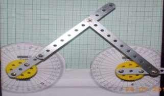
1 DC Motor Control using Fuzzy Logic Controller for Input to Five Bar Planar Mechanism Aditi A. Abhyankar #1, S. M. Chaudhari *2 # Department of Electrical Engineering, AISSMS s Institute of Information Technology, Kennedy Road, Pune, Maharashtra, India * Professor, Department of Electrical Engineering, AISSMS s Institute of Information Technology, Kennedy Road, Pune, Maharashtra, India Abstract DC motor speed and position control finds various applications in Robotics, Material handling, Industrial drives and Automation. In this paper, a control of Five Bar Mechanism Motion is obtained by DC motor position and speed control using Fuzzy rule-based system. The Five Bar Mechanism has second degree of freedom. The second degree of freedom is very difficult to handle as for the deterministic positions there can be multiple orientations. By providing the restriction of the input links and controlling the positions of the input links the degree of freedom is reduced to one. Mechanically such a restriction is possible through the use of gears which have the limitation due to gear ratio. With rule based system it is possible to achieve desired orientation of path by controlling speeds of the two DC motors. Using DC motors instead of gears one can achieve various deterministic orientations of mechanism. The dimensions of the mechanism may introduce the locking conditions. The locking condition means the two input links have the restriction of position with respect to other. The rule base system also detects the locking position and resets the system. The system is simulated using Software developed for Five Bar Planar Mechanism. The coordinates for the motion path or locus are obtained through the software. The fuzzy rule based system controls the motion of motor, such that the desired coordinates are travelled using a smooth curve. The five bar mechanism can trace the desired path with an accuracy of ±2.5%. Keywords DC Motor control, FBPM, PID, FLC. T I. INTRODUCTION he use of DC motor is very popular in Robotics, Automation, Industrial Drives systems, Material Handling etc. In these entire systems closed loop control of motor is required. The advantages to use DC motors in such systems are constant speed torque (Liner) characteristics, accurate and high control of torque, better dynamic response, high speed and simple control methods. There are many traditional methods are available to control position and speed of DC motor. In this project new control method of Fuzzy Logic Controller is designed for speed and position control of DC motor. Where DC motors will act as a drive for application of Five Bar Planar Mechanism. In the proposed system two DC motors are used as input to the first two links of Five Bar Planar Mechanism. The Five Bar Mechanism is basically used for required curve (path) tracing. The required cure can be traced by controlling speed and position of DC motor accurately. The Most popular and conventional method of close loop control is PID controller. PID controller is useful for both, speed and position control of system. PID controller needs proper tuning of controller parameters for accurate control. PID controller cannot work properly when dynamic conditions like Maximum Overshoot, Response action time. In case of Five Bar Mechanism real time conditions like mechanical locking, occurrence of unknown dynamics as friction may cause damage to the proposed system. Due to these drawbacks of PID controller, the design and implementation of new controller is discussed in this project for application of Five Bar Planar. The Fuzzy Logic Controller will be useful in real operating conditions mentioned above. Most importantly it will avoid mechanical locking of mechanism for particular curves of Mechanism by controlling speed and position of DC motors. II. PROPOSED SYSTEM A. Five bar planar mechanism (FBPM) Fig. 2.1: FBPM The Prototype of Five bar planer mechanism is shown in above Fig.2.1 FBPM has second DOF. One link is always fixed which is link 1-3 in above fig. When the input link connected to it, is set to a predefined position, it is not Page 42
2 possible to deterministically find the positions of other three links. Where as in four-bar mechanism there is a unique position of remaining two links. Hence it is the most popularly used mechanism. The mechanism has wide number of applications in the field of Material handling, Robotics and applications where coupler curve is very important. The five bar mechanism with rotation constraint reduces the DOF to one. The mechanism uses two input links connected to the fixed link. These input links have initial positional relation among themselves mentioned as θ 2 = f (θ 1 ). Further there is a relation in the speeds of input links as ω 2 = g (ω 1 ). Thus the constraints are specified in terms of angular positions and angular velocity input pin. The driver circuit has two output channels where the two motors are connected. Input voltage i.e. 24V for the DC motor is given to the input pin of driver circuit. Driver circuit needs 5V logic supply for itself which will be given by external 5V supply. The Five Bar Mechanism will be mounted on the two motors. The feedback pins i.e. encoder output of position and speed is again connected back to the Arduino controller s digital pins. Those pins will read actual position and speed of motor. At last stage DC motor drive mechanism with such speed and positions that it will trace desired curve at locking and unlocking conditions. Start B. Block diagram of system The block diagram gives a brief idea about the working of whole system. The two DC motors have operating voltage of 24 volts. On the each shaft of the two motors link 1 and link 2 of mechanism is attached respectively. The Arduino UNO (AT-mega 328) controller used for driving two DC motors based on Fuzzy Rule-base. Arduino has output voltage level 5 volts and the operating voltage of DC motors are 24 volts each. Arduino cannot provide that much voltage to drive the motor therefore there is need of the Driver Circuit which is L298n duel dc motor driver. Arduino AT-mega 328 (Microcontroller) Yes Reverse the directions of both the motors. Check w hether mechanism is having locking co-ordinates or not by formula r 1 + b + r 2 < L 1 + L 2 NO Initialise the motor parameters w ith the homepositions, initial direction and initial speed Motor 1 Driver Circuit L298 Motor 2 Input the set of co-ordinates and, d for respective co-ordinates 24V DC Supply Five bar mechanism 6 Set speed of M 1 and M 2 by Rule-based system Continue tracing of coordinates. 1 3 C. Functional Flowchart Fig. 2.2: Block diagram of proposed system. The input coordinates of the curve will be given as input to the Arduino program. The Arduino program will select the required speed and positions of the two motors based on Fuzzy Rule-base. Arduino and the motors are interfaced using the driver circuit. The output from the arduino is given to the driver circuit speed pin i.e. encoder pin and direction pin i.e. Yes Check w hether home positions are reached or not? Stop NO Fig. 2.3: Functional Flowchart of proposed system. Page 43


3 III. SIMULATION The existing software for Five Bar Mechanism developed in C++ and CG is very useful for this scope. The Software can give the different curves or path drawn by Five Bar Mechanism with set home positions. Therefore with the help of this software the co-ordinates of desired can be calculated very easily just by simulating the Five Bar Mechanism. Simulation software helps also for constructing the Fuzzy Rule Base Table. The collection of data can be done which will be used as different inputs for Fuzzy Set operations. Based on these data collection and using proper Fuzzy Inference the Fuzzy Rules can be formed. Next step will be to calculate input Speeds, Positions and Directions for desired curve using Fuzzy Rule Base table. The system is simulated in both C++ and CG as well as in MATLAB. First part will describe study of existing software used and some changes done according to DC motor position and speed control, second part will describe formulation of fuzzy rule-base system for speed and position control of motor using MATLAB. A. Simulation using existing software The Simulation for two DC motors as input to the Five Bar Mechanism is done using C++ and CG. In the simulation the Graphical User Interface (GUI) is designed. In this Project scope first using Simulation of Five Bar Mechanism the desired curves and co-ordinates on those curves are finalized. The desired curves and co-ordinates are finalized for both, Locking and Unlocking conditions. The simulation software has provision of setting the different directions, speeds and angular positions of motors to trace different co-ordinates. Fig. 3.2: Parametric values for motors given by Software for required coordinate tracing. Above figures shows an example of two co-ordinates from the set of curve, and required direction, speed, and angular position for reaching that co-ordinate. B. Simulation using MATLAB for Fuzzy Expert system. The coordinates, to be traced, are translated into the positions of the input links. The scope of the project work is related to the position and speed control of the input links. From current angular positions of the input links to the next angular positions, the motors should be rotated. It is necessary that the motors reach the angular destinations in the same amount of time. This requires the speed control of the motor during this traversal. Thus the fuzzy system will take the current position and the next position as the input. But instead of increasing the input parameters, we input the next change in the angles of the input links. Development of Fuzzy system requires defining linguistic variables and specifying problem statement so that a controller can be designed. Mamdani controller is used in this scope. Steps for designing Mamdani Controller using MATLAB software. Step 1 Defining Linguistic variables 1. Theta θ (Angle to be reached) 2. Difference between theta dθ (Difference between Theta and Current angle) 3. Speed S (Output) Fig. 3.1: Simulation using Existing Software Page 44
![Step 4 TABLE III RANGES LINGUISTIC VARIABLE S Linguistic variable Speed S Linguistic Value Notion Numerical Range Small S [40 50 60] Medium M [60 70 80] Large L [80 90 100] Step 2 Fig. 3.](/docs-images/95/123949328/images/4-0.jpg "3: Selection of Linguistic inputs and outputs in MATLAB TABLE I LINGUISTIC VARIABLE THETA θ Linguistic variable Theta θ Linguistic Value Notion Numerical Range Small S [0 15 30] Medium M [30 55 80]")
![Large L [80 110 140] Huge H [140 160 180] Step 3 TABLE II RANGES LINGUISTIC VARIABLE dθ Linguistic variable Difference between Theta, dθ (Actual angle Current angle) Linguistic Value Notion Numerical](/docs-images/95/123949328/images/4-1.jpg "Range Small S [0 0.125 0.25] Medium M [0.25 0.375 0.5] Large L [0.5 0.625 0.75] Huge H [0.747 0.872 0.997] Step 5 Fig. 3.")

4 Step 4 TABLE III RANGES LINGUISTIC VARIABLE S Linguistic variable Speed S Linguistic Value Notion Numerical Range Small S [ ] Medium M [ ] Large L [ ] Step 2 Fig. 3.3: Selection of Linguistic inputs and outputs in MATLAB TABLE I LINGUISTIC VARIABLE THETA θ Linguistic variable Theta θ Linguistic Value Notion Numerical Range Small S [ ] Medium M [ ] Large L [ ] Huge H [ ] Step 3 TABLE II RANGES LINGUISTIC VARIABLE dθ Linguistic variable Difference between Theta, dθ (Actual angle Current angle) Linguistic Value Notion Numerical Range Small S [ ] Medium M [ ] Large L [ ] Huge H [ ] Step 5 Fig. 3.5: Ranges for variable S in MATLAB Inputs are two which are Theta θ and Difference between Theta θ Linguistic values are four which are small Medium, Large and Huge. The formula for calculating the no. of rules is as follows ( ) ( ) ( ) TABLE IV FUZZY RULE-BASE TABLE Difference between Theta θ (Actual angle Current angle) Theta θ Speed(Output) S M L H S S M S S - - Fig. 3.4: Ranges for variable dθ in MATLAB L S M M H S M H H As observed in the table IV,there are 6 positions which can not be reached and hence show -.The reason behind this is we perform the direction change based on the next angular position so that the difference always remains less than 180 degrees. 180 degrees in clockwise and anticlockwise direction allow us to cover all the angular positions of the input links. Page 45
 B. Testing of Five Bar Mechanism for given curves tracing: Five bar mechanism can trace n no. of paths or coordinates.")

 The system is set to home position which has X-Y coordinates as X= 66 and Y = 150, angular position θ 1 = 90 0 and θ 2 = 90 0, speeds are zero for both motor.")
 The")
5 The change in the direction is not considered as output for Fuzzy system. Rules in matlab from above table 5.10 b) Fig. 4.1 Complete Hardware Setup Fig. 3.6: Constructing Fuzzy Rules in MATLAB Fig. 3.7: Rule Viewer in MATLAB IV. TESTING A. Hardware Setup: a) B. Testing of Five Bar Mechanism for given curves tracing: Five bar mechanism can trace n no. of paths or coordinates. In this scope for testing purpose three sets of coordinates with unlocking mechanism and one set with locking condition. For testing purpose coordinates to be traced are taken from existing simulation software mentioned in section III Simulation. Testing procedure for set 1 co-ordinate tracing is given in following section. 1) The X-Y Co-ordinates with respect to desired Curve are taken as inputs to the system. 2) The system is set to home position which has X-Y coordinates as X= 66 and Y = 150, angular position θ 1 = 90 0 and θ 2 = 90 0, speeds are zero for both motor. 3) The Fuzzy system decides speed of two motors to trace desired co-ordinates. 4) The co-ordinates traced during travel are tabulated in table 6.3. TABLE V INPUT CO-ORDINATES OF SET - 1 Set 1 X Y Theta1 Theta2 Dth1 Dth2 Dir1 Dir ) The results are compared with the results obtained in software. 6) The system tested for desired curve with respect to 5 co-ordinates in table 6.3. The co-ordinates traced by system are illustrated in fig 4.3 to Page 46


6 Fig. 4.2: Home positions of set 1 of the two motors Fig. 4.4: Position 2 of set 1 of the two motors Fig. 4.3: Position 1 of set 1 of the two motors Fig. 4.5: Position 3 of set 1 of the two motors Page 47


7 Following figures show the hardware results achieved same as the software results. Fig. 4.6: Position 4 of set 1 of the two motors Fig. 4.8: Comparison of Simulation with Actual Curve Similarly for set two and set three of co-ordinates the above procedure is repeated. Only when locking of mechanism will occur, procedure will be different. First of all the locking condition of mechanism should be studied. Following fig shows example of locking conditions and how the mechanism will get locked. Fig. 4.7: Position 5 of set 1 of the two motors a) Locking condition 1 Page 48


8 b) Locking condition 2 c) Locking condition 3 Fig. 4.9: Locking conditions of mechanism At locking conditions the speed rules will remain the same but as the locking angles are known namely the range LTH1 to + LTH1 for theta 1 and LTH 2 to + LTH 2 for theta 2 the fuzzy logic gives 0 speed to the first length which reaches the locking range the second link will continue to pass the locking range and then link 1 continues the movement. The locking range indicates that simultaneously theta 1 and theta 2 cannot be in locking range. Sr. No. Input V. RESULTS TABLE VI OBSERVATIONS OF 4 SETS Output X Y X Y Set 1 Co-ordinates : No dimensional locking % Error Set 2 Co-ordinates : No dimensional locking Set 3 Co-ordinates : Dimensional locking : Safe Set 4 Co-ordinates : Dimensional locking : Locked Observe that in set 4, when the locking mechanism is connected, the first reading is correct but for the next point given, the point is not reachable/ the mechanism goes through the locking step. As the fuzzy logic avoids the locking by stopping the motor and reversing the direction, the next points cannot be reached. The basic purpose of the fuzzy logic is also to avoid the damage to the mechanism. The locking may occur due to dimensional limitations or the construction limitations as the screws connected, may result in locking. The particular point set is chosen to indicate the locking during the traversal. If the points are given without the locking the mechanism performs correctly. The motors can stop after locking but, in the code we have implementing the recovery from locking, Fig. 5.1: Error Band VI. CONCLUSION A five bar mechanism control system, using DC motor, controlled by Fuzzy Logic Controller is design and fabricated in this project. The DC motor s speed is controlled using fuzzy logic for reaching the desired positions of mechanism. The Fuzzy logic is selected because it needs minimum speed changes to achieve desired co-ordinate position without overshoot i.e. retracing of the path. PID controller cannot avoid oscillations and response time is more than Fuzzy Logic Controller. In fuzzy we can define the rules to avoid particular angular positions in combination but in PID it will be a difficult task because in critical situation the overshoot will lock the system. The Fuzzy logic controller used will avoid locking of mechanism and will trace the desired co-ordinates. The simulation for tracing desired coordinates is done the software. Hardware is simulated and tested for set of co- Page 49
9 ordinates of locking and unlocking positions. It is observed that system traces path with an accuracy of ±2.5% but largely dependent on the mechanical system as the play in the links will increase the error. System will trace the path successfully avoiding locking conditions. REFERENCES [1] R.Manikandan R.Arulmozhiyal, Position Control of DC Servo Drive Using Fuzzy Logic Controller [2] Munadi, M. Amirullah Akbar Simulation of Fuzzy Logic Control for DC Servo Motor using Arduino based on Matlab/Simulink, 2014 International Conference on Intelligent Autonomous Agents, Networks and Systems Bandung, Indonesia, August 19-21, [3] G. Sudha, Dr. R Anita, Performance Based Comparison Between Various Z-N Tuninng PID And Fuzzy Logic PID Controller In Position Control System Of Dc Motor International Journal on Soft Computing (IJSC) Vol.3, No.3, August [4] Her-Terng Yau1, Po-Hsien Yu and Yuan-Hung Su, Design and implementation of Optimal Fuzzy-PID Controller for Dc servo motor, Appl. Math. Inf. Sci. 8, No. 1L, (2014) 231. [5] A.K. Abhyankar, S.Y. Gajjal, Simulation Model for Coupler Curve Generation using Five Bar Planar Mechanism With Rotation constraint, IJLTEMAS (ISSN ) Volume IV, Issue III, March 2015, pp [6] A.K. Abhyankar, S.Y. Gajjal, Software Modelling of Coupler Curve Generation using Five Bar Constrained Mechanism, International Journal of Mechanical Engineering and Information Technology IJMEIT (ISSN x) Volume III, Issue IV, April 2015, pp Page 50
International Journal of Advance Engineering and Research Development
 Scientific Journal of Impact Factor (SJIF): 4.14 International Journal of Advance Engineering and Research Development Volume 3, Issue 2, February -2016 e-issn (O): 2348-4470 p-issn (P): 2348-6406 SIMULATION
ISSN: (Online) Volume 2, Issue 1, January 2014 International Journal of Advance Research in Computer Science and Management Studies
 Volume 2, Issue 1, January 2014 International Journal of Advance Research in Computer Science and Management Studies") ISSN: 2321-7782 (Online) Volume 2, Issue 1, January 2014 International Journal of Advance Research in Computer Science and Management Studies Research Paper Available online at: www.ijarcsms.com Fuzzy
ISSN: 2321-7782 (Online) Volume 2, Issue 1, January 2014 International Journal of Advance Research in Computer Science and Management Studies Research Paper Available online at: www.ijarcsms.com Fuzzy
3-Degrees of Freedom Robotic ARM Controller for Various Applications
 3-Degrees of Freedom Robotic ARM Controller for Various Applications Mohd.Maqsood Ali M.Tech Student Department of Electronics and Instrumentation Engineering, VNR Vignana Jyothi Institute of Engineering
Introduction: Components used:
 Introduction: As, this robotic arm is automatic in a way that it can decides where to move and when to move, therefore it works in a closed loop system where sensor detects if there is any object in a
Robust Control Design for Rotary Inverted Pendulum Balance
 Indian Journal of Science and Technology, Vol 9(28), DOI: 1.17485/ijst/216/v9i28/9387, July 216 ISSN (Print) : 974-6846 ISSN (Online) : 974-5645 Robust Control Design for Rotary Inverted Pendulum Balance
ISSN: [IDSTM-18] Impact Factor: 5.164
![ISSN: [IDSTM-18] Impact Factor: 5.164](/thumbs/94/121360383.jpg "ISSN: [IDSTM-18] Impact Factor: 5.164") IJESRT INTERNATIONAL JOURNAL OF ENGINEERING SCIENCES & RESEARCH TECHNOLOGY SPEED CONTROL OF DC MOTOR USING FUZZY LOGIC CONTROLLER Pradeep Kumar 1, Ajay Chhillar 2 & Vipin Saini 3 1 Research scholar in
IJESRT INTERNATIONAL JOURNAL OF ENGINEERING SCIENCES & RESEARCH TECHNOLOGY SPEED CONTROL OF DC MOTOR USING FUZZY LOGIC CONTROLLER Pradeep Kumar 1, Ajay Chhillar 2 & Vipin Saini 3 1 Research scholar in
Microcontroller Based Closed Loop Speed and Position Control of DC Motor
 International Journal of Engineering and Advanced Technology (IJEAT) ISSN: 2249 8958, Volume-3, Issue-5, June 2014 Microcontroller Based Closed Loop Speed and Position Control of DC Motor Panduranga Talavaru,
Automobile Prototype Servo Control
 IJIRST International Journal for Innovative Research in Science & Technology Volume 2 Issue 10 March 2016 ISSN (online): 2349-6010 Automobile Prototype Servo Control Mr. Linford William Fernandes Don Bosco
DC Motor Speed Control: A Case between PID Controller and Fuzzy Logic Controller
 DC Motor Speed Control: A Case between PID Controller and Fuzzy Logic Controller Philip A. Adewuyi Mechatronics Engineering Option, Department of Mechanical and Biomedical Engineering, Bells University
Investigations of Fuzzy Logic Controller for Sensorless Switched Reluctance Motor Drive
 IOSR Journal of Electrical and Electronics Engineering (IOSR-JEEE) e-issn: 2278-1676,p-ISSN: 2320-3331, Volume 11, Issue 1 Ver. I (Jan Feb. 2016), PP 30-35 www.iosrjournals.org Investigations of Fuzzy
Fuzzy Logic Based Speed Control System Comparative Study
 Fuzzy Logic Based Speed Control System Comparative Study A.D. Ghorapade Post graduate student Department of Electronics SCOE Pune, India abhijit_ghorapade@rediffmail.com Dr. A.D. Jadhav Professor Department
Experiment Of Speed Control for an Electric Trishaw Based on PID Control Algorithm
 International Journal of Mechanical & Mechatronics Engineering IJMME-IJENS Vol:17 No:02 38 Experiment Of Speed Control for an Electric Trishaw Based on PID Control Algorithm Shahrizal Saat 1 *, Mohd Nabil
AUTOMATIC RESISTOR COLOUR CODING DETECTION & ALLOCATION
 AUTOMATIC RESISTOR COLOUR CODING DETECTION & ALLOCATION Abin Thomas 1, Arun Babu 2, Prof. Raji A 3 Electronics Engineering, College of Engineering Adoor (India) ABSTRACT In this modern world, the use of
Simulation of Optimal Speed Control for a DC Motor Using Conventional PID Controller and Fuzzy Logic Controller
 International Journal of Information and Computation Technology. ISSN 0974-2239 Volume 3, Number 3 (2013), pp. 181-188 International Research Publications House http://www. irphouse.com /ijict.htm Simulation
Modeling Position Tracking System with Stepper Motor
 Modeling Position Tracking System with Stepper Motor Shreeji S. Sheth 1, Pankaj Kr. Gupta 2, J. K. Hota 3 Abstract The position tracking system is used in many applications like pointing an antenna towards
Penn State Erie, The Behrend College School of Engineering
 Penn State Erie, The Behrend College School of Engineering EE BD 327 Signals and Control Lab Spring 2008 Lab 9 Ball and Beam Balancing Problem April 10, 17, 24, 2008 Due: May 1, 2008 Number of Lab Periods:
Comparative Study of PID and Fuzzy Controllers for Speed Control of DC Motor
 Comparative Study of PID and Fuzzy Controllers for Speed Control of DC Motor Osama Omer Adam Mohammed 1, Dr. Awadalla Taifor Ali 2 P.G. Student, Department of Control Engineering, Faculty of Engineering,
Design and Fabrication of Automatic Wood Drilling Machine
 Design and Fabrication of Automatic Wood Drilling Machine Deepak Devasagayam #1 Anthony Ignatious #2, Jason Kalathingal *3, Joy Kakde #4, *5 Mechanical Engineering Department, Fr. C.R.I.T., Vashi. Navi
1. Governor with dynamics: Gg(s)= 1 2. Turbine with dynamics: Gt(s) = 1 3. Load and machine with dynamics: Gp(s) = 1
= 1 2. Turbine with dynamics: Gt(s) = 1 3. Load and machine with dynamics: Gp(s) = 1") Load Frequency Control of Two Area Power System Using PID and Fuzzy Logic 1 Rajendra Murmu, 2 Sohan Lal Hembram and 3 A.K. Singh 1 Assistant Professor, 2 Reseach Scholar, Associate Professor 1,2,3 Electrical
Load Frequency Control of Two Area Power System Using PID and Fuzzy Logic 1 Rajendra Murmu, 2 Sohan Lal Hembram and 3 A.K. Singh 1 Assistant Professor, 2 Reseach Scholar, Associate Professor 1,2,3 Electrical
III. MATERIAL AND COMPONENTS USED
 Prototype Development of a Smartphone- Controlled Robotic Vehicle with Pick- Place Capability Dheeraj Sharma Electronics and communication department Gian Jyoti Institute Of Engineering And Technology,
Sensors and Sensing Motors, Encoders and Motor Control
 Sensors and Sensing Motors, Encoders and Motor Control Todor Stoyanov Mobile Robotics and Olfaction Lab Center for Applied Autonomous Sensor Systems Örebro University, Sweden todor.stoyanov@oru.se 05.11.2015
Optimal Control System Design
 Chapter 6 Optimal Control System Design 6.1 INTRODUCTION The active AFO consists of sensor unit, control system and an actuator. While designing the control system for an AFO, a trade-off between the transient
Root Locus Design. by Martin Hagan revised by Trevor Eckert 1 OBJECTIVE
 TAKE HOME LABS OKLAHOMA STATE UNIVERSITY Root Locus Design by Martin Hagan revised by Trevor Eckert 1 OBJECTIVE The objective of this experiment is to design a feedback control system for a motor positioning
is the angular velocity (speed) and friction in rotor of motor is very small (can be neglected) so Bm = 0.
 and friction in rotor of motor is very small (can be neglected) so Bm = 0.") Application case 1 Part 1: Fuzzy controller design The objective of this case study is to perform the speed control of a separately excited DC motor (figure 1) using fuzzy logic controller (FLC). The controller
Application case 1 Part 1: Fuzzy controller design The objective of this case study is to perform the speed control of a separately excited DC motor (figure 1) using fuzzy logic controller (FLC). The controller
Time Response Analysis of a DC Motor Speed Control with PI and Fuzzy Logic Using LAB View Compact RIO
 Time Response Analysis of a DC Motor Speed Control with PI and Fuzzy Logic Using LAB View Compact RIO B. Udaya Kumar 1, Dr. M. Ramesh Patnaik 2 1 Associate professor, Dept of Electronics and Instrumentation,
Australian Journal of Basic and Applied Sciences
 AENSI Journals Australian Journal of Basic and Applied Sciences ISSN:1991-8178 Journal home page: www.ajbasweb.com An Improved Low Cost Automated Mobile Robot 1 J. Hossen, 2 S. Sayeed, 3 M. Saleh, 4 P.
Development of a Fuzzy Logic Controller for Industrial Conveyor Systems
 American Journal of Science, Engineering and Technology 217; 2(3): 77-82 http://www.sciencepublishinggroup.com/j/ajset doi: 1.11648/j.ajset.21723.11 Development of a Fuzzy Logic Controller for Industrial
Mechatronics Engineering and Automation Faculty of Engineering, Ain Shams University MCT-151, Spring 2015 Lab-4: Electric Actuators
 Mechatronics Engineering and Automation Faculty of Engineering, Ain Shams University MCT-151, Spring 2015 Lab-4: Electric Actuators Ahmed Okasha, Assistant Lecturer okasha1st@gmail.com Objective Have a
Servo Tuning Tutorial
 Servo Tuning Tutorial 1 Presentation Outline Introduction Servo system defined Why does a servo system need to be tuned Trajectory generator and velocity profiles The PID Filter Proportional gain Derivative
Pick and Place Robotic Arm Using Arduino
 Pick and Place Robotic Arm Using Arduino Harish K 1, Megha D 2, Shuklambari M 3, Amit K 4, Chaitanya K Jambotkar 5 1,2,3,4 5 th SEM Students in Department of Electrical and Electronics Engineering, KLE.I.T,
Validation Document. ELEC 491 Capstone Proposal - Dynamic Projector Mount Project. Andy Kwan Smaran Karimbil Siamak Rahmanian Dante Ye
 Validation Document ELEC 491 Capstone Proposal - Dynamic Projector Mount Project Andy Kwan Smaran Karimbil Siamak Rahmanian Dante Ye Executive Summary: The purpose of this document is to describe the tests
Comparisons of Different Controller for Position Tracking of DC Servo Motor
 Comparisons of Different Controller for Position Tracking of DC Servo Motor Shital Javiya 1, Ankit Kumar 2 Assistant Professor, Dept. of IC, Atmiya Institute of Technology & Science, Rajkot, Gujarat, India
ECE 511: MICROPROCESSORS
 ECE 511: MICROPROCESSORS A project report on SNIFFING DOG Under the guidance of Prof. Jens Peter Kaps By, Preethi Santhanam (G00767634) Ranjit Mandavalli (G00819673) Shaswath Raghavan (G00776950) Swathi
2.017 DESIGN OF ELECTROMECHANICAL ROBOTIC SYSTEMS Fall 2009 Lab 4: Motor Control. October 5, 2009 Dr. Harrison H. Chin
 2.017 DESIGN OF ELECTROMECHANICAL ROBOTIC SYSTEMS Fall 2009 Lab 4: Motor Control October 5, 2009 Dr. Harrison H. Chin Formal Labs 1. Microcontrollers Introduction to microcontrollers Arduino microcontroller
Design and Development of Novel Two Axis Servo Control Mechanism
 Design and Development of Novel Two Axis Servo Control Mechanism Shailaja Kurode, Chinmay Dharmadhikari, Mrinmay Atre, Aniruddha Katti, Shubham Shambharkar Abstract This paper presents design and development
Obstacle Avoiding Robot
 Obstacle Avoiding Robot Trinayan Saharia 1, Jyotika Bauri 2, Mrs. Chayanika Bhagabati 3 1,2 Student, 3 Asst. Prof., ECE, Assam down town University, Assam Abstract: An obstacle avoiding robot is an intelligent
SPEED SYNCHRONIZATION OF MASTER SLAVE D.C. MOTORS USING MICROCONTROLLER, FOR TEXTILE APPLICATIONS
 e-issn: 2349-9745 p-issn: 2393-8161 Scientific Journal Impact Factor (SJIF): 1.711 International Journal of Modern Trends in Engineering and Research www.ijmter.com SPEED SYNCHRONIZATION OF MASTER SLAVE
Design and Implementation of PID Controller for a two Quadrant Chopper Fed DC Motor Drive
 Research Article International Journal of Current Engineering and Technology ISSN 0 0 INPRESSCO. All Rights Reserved. Available at http://inpressco.com/category/ijcet Design and Implementation of PID Controller
MOBILE ROBOT LOCALIZATION with POSITION CONTROL
 T.C. DOKUZ EYLÜL UNIVERSITY ENGINEERING FACULTY ELECTRICAL & ELECTRONICS ENGINEERING DEPARTMENT MOBILE ROBOT LOCALIZATION with POSITION CONTROL Project Report by Ayhan ŞAVKLIYILDIZ - 2011502093 Burcu YELİS
Position Control of AC Servomotor Using Internal Model Control Strategy
 Position Control of AC Servomotor Using Internal Model Control Strategy Ahmed S. Abd El-hamid and Ahmed H. Eissa Corresponding Author email: Ahmednrc64@gmail.com Abstract: This paper focuses on the design
OPTIMAL AND PID CONTROLLER FOR CONTROLLING CAMERA S POSITION IN UNMANNED AERIAL VEHICLES
 International Journal of Information Technology, Modeling and Computing (IJITMC) Vol.1,No.4,November 2013 OPTIMAL AND PID CONTROLLER FOR CONTROLLING CAMERA S POSITION IN UNMANNED AERIAL VEHICLES MOHAMMAD
Comparative analysis of Conventional MSSMC and Fuzzy based MSSMC controller for Induction Motor
 American International Journal of Research in Science, Technology, Engineering & Mathematics Available online at http://www.iasir.net ISSN (Print): 2328-3491, ISSN (Online): 2328-3580, ISSN (CD-ROM): 2328-3629
Four Quadrant Speed Control of DC Motor with the Help of AT89S52 Microcontroller
 Four Quadrant Speed Control of DC Motor with the Help of AT89S52 Microcontroller Rahul Baranwal 1, Omama Aftab 2, Mrs. Deepti Ojha 3 1,2, B.Tech Final Year (Electronics and Communication Engineering),
Modeling And Pid Cascade Control For Uav Type Quadrotor
 IOSR Journal of Dental and Medical Sciences (IOSR-JDMS) e-issn: 2279-0853, p-issn: 2279-0861.Volume 15, Issue 8 Ver. IX (August. 2016), PP 52-58 www.iosrjournals.org Modeling And Pid Cascade Control For
A Do-and-See Approach for Learning Mechatronics Concepts
 Proceedings of the 5 th International Conference of Control, Dynamic Systems, and Robotics (CDSR'18) Niagara Falls, Canada June 7 9, 2018 Paper No. 124 DOI: 10.11159/cdsr18.124 A Do-and-See Approach for
Wheeled Mobile Robot Obstacle Avoidance Using Compass and Ultrasonic
 Universal Journal of Control and Automation 6(1): 13-18, 2018 DOI: 10.13189/ujca.2018.060102 http://www.hrpub.org Wheeled Mobile Robot Obstacle Avoidance Using Compass and Ultrasonic Yousef Moh. Abueejela
MathWorks Announces Built-in Simulink Support for Arduino, BeagleBoard, and LEGO MINDSTORMS NXT
 MathWorks Announces Built-in Simulink Support for Arduino, BeagleBoard, and LEGO MINDSTORMS NXT With one click, engineers run Simulink control system and signal processing algorithms in hardware http://www.mathworks.com/company/newsroom/mathworks-announces-built-in-simulink-
The Discussion of this exercise covers the following points: Angular position control block diagram and fundamentals. Power amplifier 0.
 Exercise 6 Motor Shaft Angular Position Control EXERCISE OBJECTIVE When you have completed this exercise, you will be able to associate the pulses generated by a position sensing incremental encoder with
MEM01: DC-Motor Servomechanism
 MEM01: DC-Motor Servomechanism Interdisciplinary Automatic Controls Laboratory - ME/ECE/CHE 389 February 5, 2016 Contents 1 Introduction and Goals 1 2 Description 2 3 Modeling 2 4 Lab Objective 5 5 Model
Speed control of a DC motor using Controllers
 Automation, Control and Intelligent Systems 2014; 2(6-1): 1-9 Published online November 20, 2014 (http://www.sciencepublishinggroup.com/j/acis) doi: 10.11648/j.acis.s.2014020601.11 ISSN: 2328-5583 (Print);
AN EXPERIMENTAL INVESTIGATION OF PFC BLDC MOTOR DRIVE USING BRIDGELESS CUK DERIVED CONVERTER
 Volume 116 No. 11 2017, 141-149 ISSN: 1311-8080 (printed version); ISSN: 1314-3395 (on-line version) url: http://www.ijpam.eu doi: 10.12732/ijpam.v116i11.15 ijpam.eu AN EXPERIMENTAL INVESTIGATION OF PFC
Adaptive Neuro-Fuzzy Controler With Genetic Training For Mobile Robot Control
 Int. J. of Computers, Communications & Control, ISSN 1841-9836, E-ISSN 1841-9844 Vol. VII (2012), No. 1 (March), pp. 135-146 Adaptive Neuro-Fuzzy Controler With Genetic Training For Mobile Robot Control
SIMULINK MODELING OF FUZZY CONTROLLER FOR CANE LEVEL CONTROLLING
 International Journal of Industrial Engineering & Technology (IJIET) ISSN 2277-4769 Vol. 3, Issue 1, Mar 2013, 43-50 TJPRC Pvt. Ltd. SIMULINK MODELING OF FUZZY CONTROLLER FOR CANE LEVEL CONTROLLING YOGESH
CONTROLLER DESIGN ON ARX MODEL OF ELECTRO-HYDRAULIC ACTUATOR
 Journal of Fundamental and Applied Sciences ISSN 1112-9867 Research Article Special Issue Available online at http://www.jfas.info MODELING AND CONTROLLER DESIGN ON ARX MODEL OF ELECTRO-HYDRAULIC ACTUATOR
New Approach on Development a Dual Axis Solar Tracking Prototype
 Wireless Engineering and Technology, 2016, 7, 1-11 Published Online January 2016 in SciRes. http://www.scirp.org/journal/wet http://dx.doi.org/10.4236/wet.2016.71001 New Approach on Development a Dual
GE 320: Introduction to Control Systems
 GE 320: Introduction to Control Systems Laboratory Section Manual 1 Welcome to GE 320.. 1 www.softbankrobotics.com 1 1 Introduction This section summarizes the course content and outlines the general procedure
Performance Analysis of Ultrasonic Mapping Device and Radar
 Volume 118 No. 17 2018, 987-997 ISSN: 1311-8080 (printed version); ISSN: 1314-3395 (on-line version) url: http://www.ijpam.eu ijpam.eu Performance Analysis of Ultrasonic Mapping Device and Radar Abhishek
MODEL BASED DESIGN OF PID CONTROLLER FOR BLDC MOTOR WITH IMPLEMENTATION OF EMBEDDED ARDUINO MEGA CONTROLLER
 www.arpnjournals.com MODEL BASED DESIGN OF PID CONTROLLER FOR BLDC MOTOR WITH IMPLEMENTATION OF EMBEDDED ARDUINO MEGA CONTROLLER M.K.Hat 1, B.S.K.K. Ibrahim 1, T.A.T. Mohd 2 and M.K. Hassan 2 1 Department
Sensors and Sensing Motors, Encoders and Motor Control
 Sensors and Sensing Motors, Encoders and Motor Control Todor Stoyanov Mobile Robotics and Olfaction Lab Center for Applied Autonomous Sensor Systems Örebro University, Sweden todor.stoyanov@oru.se 13.11.2014
CHAPTER 6. CALCULATION OF TUNING PARAMETERS FOR VIBRATION CONTROL USING LabVIEW
 130 CHAPTER 6 CALCULATION OF TUNING PARAMETERS FOR VIBRATION CONTROL USING LabVIEW 6.1 INTRODUCTION Vibration control of rotating machinery is tougher and a challenging challengerical technical problem.
MICROCONTROLLERS Stepper motor control with Sequential Logic Circuits
 PH-315 MICROCONTROLLERS Stepper motor control with Sequential Logic Circuits Portland State University Summary Four sequential digital waveforms are used to control a stepper motor. The main objective
Brushed DC Motor Microcontroller PWM Speed Control with Optical Encoder and H-Bridge
 Brushed DC Motor Microcontroller PWM Speed Control with Optical Encoder and H-Bridge L298 Full H-Bridge HEF4071B OR Gate Brushed DC Motor with Optical Encoder & Load Inertia Flyback Diodes Arduino Microcontroller
INTELLIGENT SEGREGATION SYSTEM
 1, 2 3 INTELLIGENT SEGREGATION SYSTEM 1 Yogeshwar Vijay Chavan, Akash Kisan Adsul, Prof. Punam Chaudhari 3 Students, Electronics & Telecommunication, G. S. Moze College of Engineering, Balewadi,Pune, Maharashtra
SPEED CONTROL OF AN INDUCTION MOTOR USING FUZZY LOGIC AND PI CONTROLLER AND COMPARISON OF CONTROLLERS BASED ON SPEED
 SPEED CONTROL OF AN INDUCTION MOTOR USING FUZZY LOGIC AND PI CONTROLLER AND COMPARISON OF CONTROLLERS BASED ON SPEED Naveena G J 1, Murugesh Dodakundi 2, Anand Layadgundi 3 1, 2, 3 PG Scholar, Dept. of
Autonomous Machine To Manufacture PCB and 3-D Design
 Volume 119 No. 15 2018, 961-966 ISSN: 1314-3395 (on-line version) url: http://www.acadpubl.eu/hub/ http://www.acadpubl.eu/hub/ 1 Autonomous Machine To Manufacture PCB and 3-D Design Mrs. Archana Prasanthi.
A PHOTOVOLTAIC POWERED TRACKING SYSTEM FOR MOVING OBJECTS
 A PHOTOVOLTAI POWERED TRAKING SYSTEM FOR MOVING OBJETS İsmail H. Altaş* Adel M Sharaf ** e-mail: ihaltas@ktu.edu.tr e-mail: sharaf@unb.ca *: Karadeiz Technical University, Department of Electrical & Electronics
Speed Rate Corrected Antenna Azimuth Axis Positioning System
 International Journal of Electronics Engineering Research. ISSN 0975-6450 Volume 9, Number 2 (2017) pp. 151-158 Research India Publications http://www.ripublication.com Speed Rate Corrected Antenna Azimuth
Lock Cracker S. Lust, E. Skjel, R. LeBlanc, C. Kim
 Lock Cracker S. Lust, E. Skjel, R. LeBlanc, C. Kim Abstract - This project utilized Eleven Engineering s XInC2 development board to control several peripheral devices to open a standard 40 digit combination
CONTROL IMPROVEMENT OF UNDER-DAMPED SYSTEMS AND STRUCTURES BY INPUT SHAPING
 CONTROL IMPROVEMENT OF UNDER-DAMPED SYSTEMS AND STRUCTURES BY INPUT SHAPING Igor Arolovich a, Grigory Agranovich b Ariel University of Samaria a igor.arolovich@outlook.com, b agr@ariel.ac.il Abstract -
ADVANCES in NATURAL and APPLIED SCIENCES
 ADVANCES in NATURAL and APPLIED SCIENCES ISSN: 1995-0772 Published BYAENSI Publication EISSN: 1998-1090 http://www.aensiweb.com/anas 2017 Special 11(5): pages 129-137 Open Access Journal Comparison of
Design of an Intelligent Pressure Control System Based on the Fuzzy Self-tuning PID Controller
 Design of an Intelligent Pressure Control System Based on the Fuzzy Self-tuning PID Controller 1 Deepa S. Bhandare, 2 N. R.Kulkarni 1,2 Department of Electrical Engineering, Modern College of Engineering,
ARDUINO BASED DC MOTOR SPEED CONTROL
 ARDUINO BASED DC MOTOR SPEED CONTROL Student of Electrical Engineering Department 1.Hirdesh Kr. Saini 2.Shahid Firoz 3.Ashutosh Pandey Abstract The Uno is a microcontroller board based on the ATmega328P.
Autonomous Obstacle Avoiding and Path Following Rover
 Volume 114 No. 9 2017, 271-281 ISSN: 1311-8080 (printed version); ISSN: 1314-3395 (on-line version) url: http://www.ijpam.eu Autonomous Obstacle Avoiding and Path Following Rover ijpam.eu Sandeep Polina
EXPERIMENT 6: Advanced I/O Programming
 EXPERIMENT 6: Advanced I/O Programming Objectives: To familiarize students with DC Motor control and Stepper Motor Interfacing. To utilize MikroC and MPLAB for Input Output Interfacing and motor control.
SRV02-Series Rotary Experiment # 3. Ball & Beam. Student Handout
 SRV02-Series Rotary Experiment # 3 Ball & Beam Student Handout SRV02-Series Rotary Experiment # 3 Ball & Beam Student Handout 1. Objectives The objective in this experiment is to design a controller for
SRVODRV REV7 INSTALLATION NOTES
 SRVODRV-8020 -REV7 INSTALLATION NOTES Thank you for purchasing the SRVODRV -8020 drive. The SRVODRV -8020 DC servo drive is warranted to be free of manufacturing defects for 1 year from the date of purchase.
Tech Note #3: Setting up a Servo Axis For Closed Loop Position Control Application note by Tim McIntosh September 10, 2001
 Tech Note #3: Setting up a Servo Axis For Closed Loop Position Control Application note by Tim McIntosh September 10, 2001 Abstract: In this Tech Note a procedure for setting up a servo axis for closed
CHAPTER 6 OPTIMIZING SWITCHING ANGLES OF SRM
 111 CHAPTER 6 OPTIMIZING SWITCHING ANGLES OF SRM 6.1 INTRODUCTION SRM drives suffer from the disadvantage of having a low power factor. This is caused by the special and salient structure, and operational
CHAPTER 4 FUZZY LOGIC CONTROLLER
 62 CHAPTER 4 FUZZY LOGIC CONTROLLER 4.1 INTRODUCTION Unlike digital logic, the Fuzzy Logic is a multivalued logic. It deals with approximate perceptive rather than precise. The effective and efficient
ISSN Vol.05,Issue.01, January-2017, Pages:
 WWW.IJITECH.ORG ISSN 2321-8665 Vol.05,Issue.01, January-2017, Pages:0028-0032 Digital Control Strategy for Four Quadrant Operation of Three Phase BLDC Motor with Load Variations MD. HAFEEZUDDIN 1, KUMARASWAMY
Designing of a Shooting System Using Ultrasonic Radar Sensor
 2017 Published in 5th International Symposium on Innovative Technologies in Engineering and Science 29-30 September 2017 (ISITES2017 Baku - Azerbaijan) Designing of a Shooting System Using Ultrasonic Radar
Motor Modeling and Position Control Lab 3 MAE 334
 Motor ing and Position Control Lab 3 MAE 334 Evan Coleman April, 23 Spring 23 Section L9 Executive Summary The purpose of this experiment was to observe and analyze the open loop response of a DC servo
MULTI ROBOT COMMUNICATION AND TARGET TRACKING SYSTEM AND IMPLEMENTATION OF ROBOT USING ARDUINO
 MULTI ROBOT COMMUNICATION AND TARGET TRACKING SYSTEM AND IMPLEMENTATION OF ROBOT USING ARDUINO K. Sindhuja 1, CH. Lavanya 2 1Student, Department of ECE, GIST College, Andhra Pradesh, INDIA 2Assistant Professor,
Pan-Tilt Signature System
 Pan-Tilt Signature System Pan-Tilt Signature System Rob Gillette Matt Cieloszyk Luke Bowen Final Presentation Introduction Problem Statement: We proposed to build a device that would mimic human script
Control Strategies for BLDC Motor
 Control Strategies for BLDC Motor Pritam More 1, V.M.Panchade 2 Student, Department of Electrical Engineering, G. H. Raisoni Institute of Engineering and Technology, Pune, Savitribai Phule Pune University,
Assembly Guide Robokits India
 Robotic Arm 5 DOF Assembly Guide Robokits India info@robokits.co.in Robokits World http://www.robokitsworld.com http://www.robokitsworld.com Page 1 Overview : 5 DOF Robotic Arm from Robokits is a robotic
Fuzzy logic control implementation in sensorless PM drive systems
 Philadelphia University, Jordan From the SelectedWorks of Philadelphia University, Jordan Summer April 2, 2010 Fuzzy logic control implementation in sensorless PM drive systems Philadelphia University,
EE 314 Spring 2003 Microprocessor Systems
 EE 314 Spring 2003 Microprocessor Systems Laboratory Project #9 Closed Loop Control Overview and Introduction This project will bring together several pieces of software and draw on knowledge gained in
Position Control of Servo Systems using PID Controller Tuning with Soft Computing Optimization Techniques
 Position Control of Servo Systems using PID Controller Tuning with Soft Computing Optimization Techniques P. Ravi Kumar M.Tech (control systems) Gudlavalleru engineering college Gudlavalleru,Andhra Pradesh,india
Design of Compensator for Dynamical System
 Design of Compensator for Dynamical System Ms.Saroja S. Chavan PimpriChinchwad College of Engineering, Pune Prof. A. B. Patil PimpriChinchwad College of Engineering, Pune ABSTRACT New applications of dynamical
MAE106 Laboratory Exercises Lab # 5 - PD Control of DC motor position
 MAE106 Laboratory Exercises Lab # 5 - PD Control of DC motor position University of California, Irvine Department of Mechanical and Aerospace Engineering Goals Understand how to implement and tune a PD
G320X MANUAL DC BRUSH SERVO MOTOR DRIVE
 G320X MANUAL DC BRUSH SERVO MOTOR DRIVE Thank you for purchasing the G320X drive. The G320X DC servo drive is warranted to be free of manufacturing defects for 3 years from the date of purchase. Any customer
ECE 5670/ Lab 5. Closed-Loop Control of a Stepper Motor. Objectives
 1. Introduction ECE 5670/6670 - Lab 5 Closed-Loop Control of a Stepper Motor Objectives The objective of this lab is to develop and test a closed-loop control algorithm for a stepper motor. First, field
Datasheet of the MEZ Stepper Servo Drive MEZ 2D VDC, 8.2A Peak, Closed-loop, No Tuning. Version
 Datasheet of the MEZ Stepper Servo Drive MEZ D880 4-75VDC, 8.A Peak, Closed-loop, No Tuning Version 0.1.1 http://www.motionking.com Features Step and direction control Closed position loop for no loss
A Brushless DC Motor Speed Control By Fuzzy PID Controller
 A Brushless DC Motor Speed Control By Fuzzy PID Controller M D Bhutto, Prof. Ashis Patra Abstract Brushless DC (BLDC) motors are widely used for many industrial applications because of their low volume,
FUZZY LOGIC CONTROLLER BASED SPEED CONTROL OF THREE PHASE INDUCTION MOTOR
 FUZZY LOGIC CONTROLLER BASED SPEED CONTROL OF THREE PHASE INDUCTION MOTOR Sharda Chande 1, Pranali Khanke 2 1 PG Scholar, Electrical Power System, Electrical Engineering Department, Ballarpur Institute
DC motor control using arduino
 DC motor control using arduino 1) Introduction: First we need to differentiate between DC motor and DC generator and where we can use it in this experiment. What is the main different between the DC-motor,
ME375 Lab Project. Bradley Boane & Jeremy Bourque April 25, 2018
 ME375 Lab Project Bradley Boane & Jeremy Bourque April 25, 2018 Introduction: The goal of this project was to build and program a two-wheel robot that travels forward in a straight line for a distance
DCS Series Brush DC Servo Drive. Datasheet
 DCS Series Brush DC Servo Drive Datasheet Version DCS-2014-01 http://www.primopal.com DCS series Brush DC Servo Drives Description PrimoPal s DCS series Brush DC Servo Drive are fully digital brushed servo
A PID Controlled Real Time Analysis of DC Motor
 A PID Controlled Real Time Analysis of DC Motor Saurabh Dubey 1, Dr. S.K. Srivastava 2 Research Scholar, Dept. of Electrical Engineering, M.M.M Engineering College, Gorakhpur, India 1 Associate Professor,