Via del Carroccio, 4 I Biassono (Italy) TRFFCC
|
|
|
- Peregrine Parker
- 5 years ago
- Views:
Transcription
1 I Biassono (Italy) Report Reference ID: TRFFCC Test specification: Title 47 - Telecommunication Chapter I - Federal Communications Commission Subchapter A - General Part 15 - Radio Devices Subpart C - Intentional Radiators Operation within the bands MHz RSS-247 Issue 1 May 2015 Spectrum Management and Telecommunications Radio Standards Specification Digital Transmission Systems (DTSs), Hopping Systems (FHSs) and Licence-Exempt Local Area Network (LE-LAN) Devices Applicant: Apparatus: Model: FCC ID: IC Registration Number: Univet Srl Via Giovanni Prati, Rezzato (BS) Italy Multi-lens optical system EOS HP Remote control 2AKOL-EOSHPT EOSHPT Testing laboratory: Telephone: Facsimile: Tested by: Name and title P. Barbieri, Wireless/EMC Specialist Date Reviewed by: G. Curioni, Wireless/EMC Specialist authorizes the applicant to reproduce this report provided it is reproduced in its entirety and for use by the company s employees only. Any use which a third party makes of this report, or any reliance on or decisions to be made based on it, are the responsibility of such third parties. accepts no responsibility for damages, if any, suffered by any third party as a result of decisions made or actions based on this report. This report shall not be reproduced except in full without the written approval of the testing laboratory. This Test Report, when bearing the Nemko name and logo is only valid when issued by a Nemko laboratory, or by a laboratory having special agreement with Nemko.
2 I Biassono (Italy) Table of contents Section 1: Report summary Test specification Statement of compliance Exclusions Registration number Test report revision history Limits of responsibility... 3 Section 2: Summary of test results FCC Part 15 Subpart C Intentional Radiators, RSS-247 test results... 4 Section 3: Equipment under test (EUT) and application details Applicant details Modular equipment Product details Application purpose Composite/related equipment Sample information EUT technical specifications Operation of the EUT during testing EUT setup diagram... 7 Section 4: Engineering considerations Modifications incorporated in the EUT Deviations from laboratory tests procedures Technical judgment... 8 Section 5: Test conditions Power source and ambient temperatures... 9 Section 6: Measurement uncertainty Section 7: Test equipment Test equipment list Clause 15.31(e) Variation of power source Clause 15.31(m) Number of operating frequencies Clause Antenna requirement Clause (b) Maximum peak conducted output power Clause (d) Spurious emissions Clause (a)(2) Minimum 6 db bandwidth Clause (e) Power spectral density for digitally modulated devices Setup photos Section 9: Block diagrams of test set-ups Section 10: EUT photos Report reference ID: TRFFCC Page 2 of 80
3 Section 1: Report summary Section 1: Report summary 1.1 Test specification Specifications FCC Part 15 Subpart C, Operation within the bands MHz, MHz and MHz. RSS-247 Issue 1 May 2015 Spectrum Management and Telecommunications Radio Standards Specification Digital Transmission Systems (DTSs), Hopping Systems (FHSs) and Licence- Exempt Local Area Network (LE-LAN) Devices 1.2 Statement of compliance Compliance In the configuration tested the EUT was found compliant Yes No This report contains an assessment of apparatus against specifications based upon tests carried out on samples submitted at Nemko Canada Inc. These tests were conducted on a sample of the equipment for the purpose of demonstrating compliance with Part 15; Subpart C. and RSS-247 Issue 1 May Radiated tests were conducted in accordance with ANSI C Exclusions Exclusions None 1.4 Registration number Test site FCC ID number: / IC number: 9109A 1.5 Test report revision history Revision # Details of changes made to test report TRF Original report issued 1.6 Limits of responsibility Note that the results contained in this report relate only to the items tested and were obtained in the period between the date of initial receipt of samples and the date of issue of the report. This test report has been completed in accordance with the requirements of ISO/IEC All results contain in this report are within Nemko Italy s ISO/IEC accreditation. Nemko S.p.A. authorizes the applicant to reproduce this report provided it is reproduced in its entirety and for use by the company s employees only. Any use which a third party makes of this report, or any reliance on or decisions to be made based on it, are the responsibility of such third parties. Nemko S.p.A. accepts no responsibility for damages, if any, suffered by any third party as a result of decisions made or actions based on this report. Report reference ID: TRFFCC Page 3 of 80
4 Section 2: Summary of test results Section 2: Summary of test results 2.1 FCC Part 15 Subpart C Intentional Radiators, RSS-247 test results General requirements for FCC Part 15, RSS-Gen Issue 4 November 2014 FCC Part Test description Verdict 15.31(e) Variation of power source Pass 15.31(m) Number of operating frequencies Pass Antenna requirement Pass (a) Conducted limits N/A Specific requirements for FCC Part 15 Subpart C (clause ), RSS-247 Issue 1 May 2015 (clause 5.2) FCC Part Test description Verdict (a)(1)(i) hopping systems operating in the MHz band N/A (a)(1)(ii) hopping systems operating in the MHz band N/A (a)(1)(iii) hopping systems operating in the MHz band N/A (a)(2) (b)(1) 5.4(2) (b)(2) (b)(3) Minimum 6 db bandwidth for systems using digital modulation techniques Maximum peak output power of frequency hopping systems operating in the MHz band and MHz band Maximum peak output power of hopping systems operating in the MHz band Maximum peak output power of systems using digital modulation in the MHz, MHz, and MHz bands (b)(4) Maximum peak output power N/A (c)(1) (c)(2) Fixed point-to-point operation with directional antenna gains greater than 6 dbi Transmitters operating in the MHz band that emit multiple directional beams (d) 5.5 Spurious emissions Pass (e) Power spectral density for digitally modulated devices Pass (f) Time of occupancy for hybrid systems N/A Notes: None Pass N/A N/A Pass N/A N/A Report reference ID: TRFFCC Page 4 of 80
5 Section 3: EUT and application details Section 3: Equipment under test (EUT) and application details 3.1 Applicant details Applicant complete business name Name: Univet Srl Federal Registration Number (FRN): Grantee code: 2AKOL IC company number: Mailing address Address: Via Giovanni Prati, 87 City: Province/State: Rezzato BS Post code: Country: Italy 3.2 Modular equipment a) Single modular approval b) Limited single modular approval Single modular approval Yes No Limited single modular approval Yes No 3.3 Product details FCC ID / IC ID Equipment class Description of product as it is marketed FCC 2AKOL-EOSHPT IC EOSHPT Digital Transmission Systems (BLE) Multi-lens optical system Model name/number: EOS HP Variant name/number Application purpose Type of application Original certification Change in identification of presently authorized equipment Original FCC ID: Grant date: Class II permissive change or modification of presently authorized equipment Report reference ID: TRFFCC Page 5 of 80
6 Section 3: EUT and application details 3.5 Composite/related equipment a) Composite The EUT is a composite device subject to an additional equipment authorization equipment Yes No b) Related equipment The EUT is part of a system that operates with, or is marketed with, another device that requires an equipment authorization Yes No c) Related FCC ID If either of the above is yes : ID has been granted under the FCC ID(s) listed below: is in the process of being filled under the FCC ID(s) listed below: is pending with the FCC ID(s) listed below: has a mix of pending and granted statues under the FCC ID(s) listed below: 2AKOL-EOSHPC 3.6 Sample information Receipt date: Nemko sample ID number: EUT technical specifications Operating band: GHz ~ GHz Operating frequency: 2402 MHz (CH0) to 2480 MHz (CH39) Modulation type: GFSK Occupied bandwidth: 729 khz Channel spacing: 2 MHz Emission designator: 729KF7D Antenna type: Johanson Technology antenna model 2450AT18D0100 with a gain of 1.5 dbi Power source: 3.0 V DC from CR2032 battery Report reference ID: TRFFCC Page 6 of 80
7 Section 3: EUT and application details 3.8 Operation of the EUT during testing Details: Constant transmitting at maximum power and at lower, middle and higher frequency with GSFK modulation. 3.9 EUT setup diagram CONTROL UNIT RADIO LINK RF REMOT CONTROLLER LED LAMP LAMP CABLE Report reference ID: TRFFCC Page 7 of 80
8 Section 4: Engineering considerations Section 4: Engineering considerations 4.1 Modifications incorporated in the EUT Modifications performed to the EUT during this assessment Modifications Yes, performed by Client or Nemko None Details: 4.2 Deviations from laboratory tests procedures Deviations from laboratory test procedures Deviations Yes - details are listed below: None 4.3 Technical judgment Judgment None Report reference ID: TRFFCC Page 8 of 80
9 Section 5: Test conditions Section 5: Test conditions 5.1 Power source and ambient temperatures Normal temperature, humidity and air pressure test conditions Power supply range: Temperature: C Relative humidity: % Air pressure: kpa When it is impracticable to carry out tests under these conditions, a note to this effect stating the ambient temperature and relative humidity during the tests shall be recorded and stated. The normal test voltage for equipment to be connected to the mains shall be the nominal mains voltage. For the purpose of the present document, the nominal voltage shall be the declared voltage, or any of the declared voltages ±5 %, for which the equipment was designed. Report reference ID: TRFFCC Page 9 of 80
10 Section 6: Measurement uncertainty Section 6: Measurement uncertainty The data and results referenced in this document are true and accurate. The reader is cautioned that there may be errors within the calibration limits of the equipment and facilities. The measurement uncertainty was calculated for all measurements listed in this test report according Technical Procedure WML0078. Furthermore, component and process variability of devices similar to that tested may result in additional deviation. The manufacturer has the sole responsibility of continued compliance of the device. Hereafter the best measurement capability for laboratory is reported: EUT Type Test Range and Setup features Transmitter Receiver Conducted Radiated Radiated Measurement Uncertainty error 0.001MHz 18 GHz 0.08 ppm (1) Carrier power RF Output Power 1MHz 18 GHz With power meter 1MHz 18 GHz With spectrum/receiver Notes 1.6 db (1) 3.0 db (1) Adjacent channel power 1MHz 18 GHz 1.6 db (1) Conducted spurious emissions 1MHz 18 GHz 4.2 db (1) Intermodulation attenuation 1MHz 18 GHz 2.2 db (1) Attack time frequency behaviour 1MHz 18 GHz 2.0 ms (1) Attack time power behaviour 1MHz 18 GHz 2.5 ms (1) Release time frequency behaviour 1MHz 18 GHz 2.0 ms (1) Release time power behaviour 1MHz 18 GHz 2.5 ms (1) Transient behaviour of the transmitter Transient frequency behaviour Transient behaviour of the transmitter Power level slope deviation - Maximum permissible frequency deviation deviation - Response of the transmitter to modulation frequencies above 3 khz 1MHz 18 GHz 0.2 khz (1) 1MHz 18 GHz 9% (1) 0.001MHz 18 GHz 1.3% (1) 0.001MHz 18 GHz 0.5 db (1) Dwell time - 3% (1) Hopping Separation 0.01MHz 18 GHz 1% (1) Occupied Channel Bandwidth 0.01MHz 18 GHz 2% (1) Modulation Bandwidth 0.01MHz 18 GHz 2% (1) Radiated spurious emissions 30MHz 18 GHz 6.0 db (1) Effective radiated power transmitter 30MHz 18 GHz 6.0 db (1) Radiated spurious emissions 30MHz 18 GHz 6.0 db (1) Sensitivity measurement 1MHz 18 GHz 6.0 db (1) Conducted Conducted spurious emissions 1MHz 18 GHz 4.2 db (1) NOTES: (1) The reported expanded uncertainty of measurement is stated as the standard uncertainty of measurement multiplied by the coverage factor k = 2 which has been derived from the assumed normal probability distribution with infinite degrees of freedom and for a coverage probability of 95 %. Report reference ID: TRFFCC Page 10 of 80
11 Section 7: Test equipment Section 7: Test equipment 7.1 Test equipment list Equipment Manufacturer Model No. Asset/Serial No. Next cal. Spectrum Analizer (9 KHz 40 GHz) R&S FSEK / /01 EMI receiver (20 Hz 8 GHz) R&S ESU /09 Broadband preamplifier (1 GHz 18 GHz) Schwarzbeck BBV /12 Bilog antenna (1 GHz 18 GHz) Schwarzbeck STLP /06 Trilog Broadband Antenna Schwarzbeck VULB /07 Double Ridged Horn (4 GHz 40 GHz) RF SPIN DRH A /08 Wide band Amplifier (18 GHz 40 GHz) MITEQ JS P-R /12 Semi-anechoic chamber Nemko 10m semi-anechoic chamber /10 Antenna mast R&S HCM /05 NCR Controller R&S HCC /7 NCR Turning-table R&S HCT /03 NCR Note: N/A = Not applicable, NCR = No calibration required, COU = Cal on use Report reference ID: TRFFCC Page 11 of 80
12 Specification: FCC Part 15 Subpart A 8.1 Clause 15.31(e) Variation of power source Measurement standards. (e) For intentional radiators, measurements of the variation of the input power or the radiated signal level of the fundamental frequency component of the emission, as appropriate, shall be performed with the supply voltage varied between 85 % and 115 % of the nominal rated supply voltage. For battery-operated equipment, the equipment tests shall be performed using a new battery. Special notes None Test data New battery was used during the tests Report reference ID: TRFFCC Page 12 of 80
13 Specification: FCC Part 15 Subpart A 8.2 Clause 15.31(m) Number of operating frequencies Measurement standards. (m) Measurements on intentional radiators or receivers, other than TV broadcast receivers, shall be performed and, if required, reported for each band in which the device can be operated with the device operating at the number of frequencies in each band specified in the following table: range over which device operates Number of frequencies Location in the range of operation 1 MHz and less 1 Middle 1 to 10 MHz 2 1 near top and 1 near bottom More than 10 MHz 3 1 near top, 1 near middle and 1 near bottom Special notes None Test data The frequency band is MHz therefore number of operating frequencies is 3. Low frequency / channel 2402 MHz Mid frequency / channel 2440 MHz High frequency / channel 2480 MHz Report reference ID: TRFFCC Page 13 of 80

14 Specification: FCC Part 15 Subpart C 8.3 Clause Antenna requirement Antenna requirement. An intentional radiator shall be designed to ensure that no antenna other than that furnished by the responsible party shall be used with the device. The use of a permanently attached antenna or of an antenna that uses a unique coupling to the intentional radiator shall be considered sufficient to comply with the provisions of this section. The manufacturer may design the unit so that a broken antenna can be replaced by the user, but the use of a standard antenna jack or electrical connector is prohibited. This requirement does not apply to carrier current devices or to devices operated under the provisions of , , , , or Further, this requirement does not apply to intentional radiators that must be professionally installed, such as perimeter protection systems and some field disturbance sensors, or to other intentional radiators which, in accordance with 15.31(d), must be measured at the installation site. However, the installer shall be responsible for ensuring that the proper antenna is employed so that the limits in this part are not exceeded. Special notes None Test data The EUT uses a Johanson Technology antenna model 2450AT18D0100 mounted on the printed circuit board. ANTENNA Report reference ID: TRFFCC Page 14 of 80
15 8.4 Clause (b) Maximum peak conducted output power FCC Operation within the bands MHz, MHz, and MHz. (b) The maximum peak conducted output power of the intentional radiator shall not exceed the following: (1) For frequency hopping systems operating in the MHz band employing at least 75 nonoverlapping hopping channels, and all frequency hopping systems in the MHz band: 1 watt. For all other frequency hopping systems in the MHz band: watts. (2) For frequency hopping systems operating in the MHz band: 1 watt for systems employing at least 50 hopping channels; and, 0.25 watts for systems employing less than 50 hopping channels, but at least 25 hopping channels, as permitted under paragraph (a)(1)(i) of this section. (3) For systems using digital modulation in the MHz, MHz, and MHz bands: 1 Watt. As an alternative to a peak power measurement, compliance with the one Watt limit can be based on a measurement of the maximum conducted output power. Maximum Conducted Output Power is defined as the total transmit power delivered to all antennas and antenna elements averaged across all symbols in the signaling alphabet when the transmitter is operating at its maximum power control level. Power must be summed across all antennas and antenna elements. The average must not include any time intervals during which the transmitter is off or is transmitting at a reduced power level. If multiple modes of operation are possible (e.g., alternative modulation methods), the maximum conducted output power is the highest total transmit power occurring in any mode. (4) The conducted output power limit specified in paragraph (b) of this section is based on the use of antennas with directional gains that do not exceed 6 dbi. Except as shown in paragraph (c) of this section, if transmitting antennas of directional gain greater than 6 dbi are used, the conducted output power from the intentional radiator shall be reduced below the stated values in paragraphs (b)(1), (b)(2), and (b)(3) of this section, as appropriate, by the amount in db that the directional gain of the antenna exceeds 6 dbi. (i) Systems operating in the MHz band that are used exclusively for fixed, point-to-point operations may employ transmitting antennas with directional gain greater than 6 dbi provided the maximum peak output power of the intentional radiator is reduced by 1 db for every 3 db that the directional gain of the antenna exceeds 6 dbi. (ii) Systems operating in the MHz band that are used exclusively for fixed, point-to-point operations may employ transmitting antennas with directional gain greater than 6 dbi without any corresponding reduction in transmitter peak output power. (iii) Fixed, point-to-point operation, as used in paragraphs (b)(3)(i) and (b)(3)(ii) of this section, excludes the use of point-to-multipoint systems, omnidirectional applications, and multiple co-located intentional radiators transmitting the same information. The operator of the spread spectrum intentional radiator or, if the equipment is professionally installed, the installer is responsible for ensuring that the system is used exclusively for fixed, point-to-point operations. The instruction manual furnished with the intentional radiator shall contain language in the installation instructions informing the operator and the installer of this responsibility. RSS-247 Clause 5.4 (4) For DTSs employing digital modulation techniques operating in the bands MHz and MHz, the maximum peak conducted output power shall not exceed 1W. Except as provided in Section 5.4(5), the e.i.r.p. shall not exceed 4 W. Special notes None Report reference ID: TRFFCC Page 15 of 80
16 Test data Radiated measurements Radiated measurements were performed a distance of 3 m and according to ANSI C Antenna polarization EUT position Field strength 2402 Horizontal Horizontal Horizontal Horizontal Horizontal Horizontal Vertical Horizontal Vertical Horizontal Vertical Horizontal Horizontal Vertical Horizontal Vertical Horizontal Vertical Vertical Vertical Vertical Vertical Vertical Vertical 98.6 Theoretical conversion from Field Strength measured at 3 m to power conducted from the intentional radiator to the antenna: P (W) = 2 E R 30G 2 E = Measured field strength value (V/m) R = Measurement distance (m) G = Antenna Gain (numeric) Therefore dbw = dbv/m + 20Log(3) 10Log(30) 10Log(G) From which we obtain dbmw = dbµv/m Log(3) 10Log(30) 10Log(G) + 30 = dbµv/m Log(G) Output power [dbm] = Field Strength [dbµv/m] [db] Antenna gain [dbi] Field strength Output power (dbm) Limit (dbm) EIRP (dbm) EIRP limit (dbm) Report reference ID: TRFFCC Page 16 of 80
17 8.5 Clause (d) Spurious emissions Operation within the bands MHz, MHz, and MHz. (d) In any 100 khz bandwidth outside the frequency band in which the spread spectrum or digitally modulated intentional radiator is operating, the radio frequency power that is produced by the intentional radiator shall be at least 20 db below that in the 100 khz bandwidth within the band that contains the highest level of the desired power, based on either an RF conducted or a radiated measurement, provided the transmitter demonstrates compliance with the peak conducted power limits. If the transmitter complies with the conducted power limits based on the use of RMS averaging over a time interval, as permitted under paragraph (b)(3) of this section, the attenuation required under this paragraph shall be 30 db instead of 20 db. Attenuation below the general limits specified in (a) is not required. In addition, radiated emissions which fall in the restricted bands, as defined in (a), must also comply with the radiated emission limits specified in (a) (see (c)). RSS-247 Clause 5.5 (Unwanted Emissions) In any 100 khz bandwidth outside the frequency band in which the spread spectrum or digitally modulated device is operating, the RF power that is produced shall be at least 20 db below that in the 100 khz bandwidth within the band that contains the highest level of the desired power, based on either an RF conducted or a radiated measurement, provided that the transmitter demonstrates compliance with the peak conducted power limits. If the transmitter complies with the conducted power limits based on the use of root-mean-square averaging over a time interval, as permitted under Section 5.4(4), the attenuation required shall be 30 db instead of 20 db. Attenuation below the general field strength limits specified in RSS-Gen is not required. Special notes Radiated emission limits (µv/m) Field strength Measurement distance (m) /F log(F) /F log(F) above Notes: F = fundamental frequency in khz In the emission table above, the tighter limit applies at the band edges. For frequencies above 1 GHz the limit on peak RF emissions is 20 db above the maximum permitted average emission limit applicable to the equipment under test. Report reference ID: TRFFCC Page 17 of 80
18 Special notes Restricted bands of operation MHz MHz MHz GHz Above The spectrum was searched from 30 MHz to the 10 th harmonic. The EUT was measured on three orthogonal axis. All measurements were performed at a distance of 3 m. All measurements were performed: within MHz range: using a quasi-peak detector with 120 khz RBW within MHz range: using a peak detector with 100 khz/300 khz RBW/VBW, above 1 GHz: using peak detector with 1 MHz/3 MHz RBW/VBW for peak results above 1 GHz: using average detector with 1 MHz/3 MHz RBW/VBW for average results Report reference ID: TRFFCC Page 18 of 80
 When the radiated emission limits are expressed in terms of the average value of the emission, and pulsed operation is employed, the measurement field strength shall be determined by")

19 Test data Duty cycle/average factor calculations 15.35(c) When the radiated emission limits are expressed in terms of the average value of the emission, and pulsed operation is employed, the measurement field strength shall be determined by averaging over one complete pulse train, including blanking intervals, as long as the pulse train does not exceed 0.1 seconds. Duty cycle/average factor calculations: The first burst is generated by the remote controller and the second by the control unit. The single burst have a duration of 117 µs and it s repeated every 468 µs. Duty cycle / average factor = 20 log Tx100 ms 100ms Transmission time = 117 µs every 468 µs = 25 ms Duty cycle correction = db 10 Report reference ID: TRFFCC Page 19 of 80
20 Horizontal 3 m Horizontal Low QP field strength Limit Margin H H H H Report reference ID: TRFFCC Page 20 of 80
21 Vertical 3 m Horizontal Low QP field strength Limit Margin V V V V Report reference ID: TRFFCC Page 21 of 80
22 Horizontal 3 m Vertical Low QP field strength Limit Margin H H H H Report reference ID: TRFFCC Page 22 of 80
23 Vertical 3 m Vertical Low QP field strength Limit Margin V V V V Report reference ID: TRFFCC Page 23 of 80
24 Horizontal 3 m Horizontal Mid QP field strength Limit Margin H H H H Report reference ID: TRFFCC Page 24 of 80
25 Vertical 3 m Horizontal Mid QP field strength Limit Margin V V V V Report reference ID: TRFFCC Page 25 of 80
26 Horizontal 3 m Vertical Mid QP field strength Limit Margin H H H H Report reference ID: TRFFCC Page 26 of 80
27 Vertical 3 m Vertical Mid QP field strength Limit Margin V V V V Report reference ID: TRFFCC Page 27 of 80
28 Horizontal 3 m Horizontal High QP field strength Limit Margin H H H H Report reference ID: TRFFCC Page 28 of 80
29 Vertical 3 m Horizontal High QP field strength Limit Margin V V V V Report reference ID: TRFFCC Page 29 of 80
30 Horizontal 3 m Vertical High QP field strength Limit Margin H H H H Report reference ID: TRFFCC Page 30 of 80
31 Vertical 3 m Vertical High QP field strength Limit Margin V V V V Report reference ID: TRFFCC Page 31 of 80
32 Horizontal 3 m Horizontal Low Peak field strength Duty cycle corr. Avg field strength Avg limit Avg margin 2402 H Report reference ID: TRFFCC Page 32 of 80
33 Vertical 3 m Horizontal Low Peak field strength Duty cycle corr. Avg field strength Avg limit Avg margin 2402 V Report reference ID: TRFFCC Page 33 of 80
34 Horizontal 3 m Vertical Low Peak field strength Duty cycle corr. Avg field strength Avg limit Avg margin 2402 H H Report reference ID: TRFFCC Page 34 of 80
35 Vertical 3 m Vertical Low Peak field strength Duty cycle corr. Avg field strength Avg limit Avg margin 2402 V Report reference ID: TRFFCC Page 35 of 80
36 Horizontal 3 m Horizontal Mid Peak field strength Duty cycle corr. Avg field strength Avg limit Avg margin 2440 H Report reference ID: TRFFCC Page 36 of 80
37 Vertical 3 m Horizontal Mid Peak field strength Duty cycle corr. Avg field strength Avg limit Avg margin 2440 V Report reference ID: TRFFCC Page 37 of 80
38 Horizontal 3 m Vertical Mid Peak field strength Duty cycle corr. Avg field strength Avg limit Avg margin 2440 H H Report reference ID: TRFFCC Page 38 of 80
39 Vertical 3 m Vertical Mid Peak field strength Duty cycle corr. Avg field strength Avg limit Avg margin 2440 V Report reference ID: TRFFCC Page 39 of 80
40 Horizontal 3 m Horizontal High Peak field strength Duty cycle corr. Avg field strength Avg limit Avg margin 2480 H Report reference ID: TRFFCC Page 40 of 80
41 Vertical 3 m Horizontal High Peak field strength Duty cycle corr. Avg field strength Avg limit Avg margin 2480 V V Report reference ID: TRFFCC Page 41 of 80
42 Horizontal 3 m Vertical High Peak field strength Duty cycle corr. Avg field strength Avg limit Avg margin 2480 H Report reference ID: TRFFCC Page 42 of 80
43 Vertical 3 m Vertical High Peak field strength Duty cycle corr. Avg field strength Avg limit Avg margin 2480 V Report reference ID: TRFFCC Page 43 of 80
44 Horizontal 3 m Horizontal Low Peak field strength Duty cycle corr. Avg field strength Avg limit Avg margin Report reference ID: TRFFCC Page 44 of 80
45 Vertical 3 m Horizontal Low Peak field strength Duty cycle corr. Avg field strength Avg limit Avg margin Report reference ID: TRFFCC Page 45 of 80
46 Horizontal 3 m Vertical Low Peak field strength Duty cycle corr. Avg field strength Avg limit Avg margin Report reference ID: TRFFCC Page 46 of 80
47 Vertical 3 m Vertical Low Peak field strength Duty cycle corr. Avg field strength Avg limit Avg margin Report reference ID: TRFFCC Page 47 of 80
48 Horizontal 3 m Horizontal Mid Peak field strength Duty cycle corr. Avg field strength Avg limit Avg margin Report reference ID: TRFFCC Page 48 of 80
49 Vertical 3 m Horizontal Mid Peak field strength Duty cycle corr. Avg field strength Avg limit Avg margin Report reference ID: TRFFCC Page 49 of 80
50 Horizontal 3 m Vertical Mid Peak field strength Duty cycle corr. Avg field strength Avg limit Avg margin Report reference ID: TRFFCC Page 50 of 80
51 Vertical 3 m Vertical Mid Peak field strength Duty cycle corr. Avg field strength Avg limit Avg margin Report reference ID: TRFFCC Page 51 of 80
52 Horizontal 3 m Horizontal High Peak field strength Duty cycle corr. Avg field strength Avg limit Avg margin Report reference ID: TRFFCC Page 52 of 80
53 Vertical 3 m Horizontal High Peak field strength Duty cycle corr. Avg field strength Avg limit Avg margin Report reference ID: TRFFCC Page 53 of 80
54 Horizontal 3 m Vertical High Peak field strength Duty cycle corr. Avg field strength Avg limit Avg margin Report reference ID: TRFFCC Page 54 of 80
55 Vertical 3 m Vertical High Peak field strength Duty cycle corr. Avg field strength Avg limit Avg margin Report reference ID: TRFFCC Page 55 of 80
56 Horizontal 3 m Horizontal Low Peak field strength Duty cycle corr. Avg field strength Avg limit Avg margin Report reference ID: TRFFCC Page 56 of 80
57 Vertical 3 m Horizontal Low Peak field strength Duty cycle corr. Avg field strength Avg limit Avg margin Report reference ID: TRFFCC Page 57 of 80
58 Horizontal 3 m Vertical Low Peak field strength Duty cycle corr. Avg field strength Avg limit Avg margin Report reference ID: TRFFCC Page 58 of 80
59 Vertical 3 m Vertical Low Peak field strength Duty cycle corr. Avg field strength Avg limit Avg margin Report reference ID: TRFFCC Page 59 of 80
60 Horizontal 3 m Horizontal Mid Peak field strength Duty cycle corr. Avg field strength Avg limit Avg margin Report reference ID: TRFFCC Page 60 of 80
61 Vertical 3 m Horizontal Mid Peak field strength Duty cycle corr. Avg field strength Avg limit Avg margin Report reference ID: TRFFCC Page 61 of 80
62 Horizontal 3 m Vertical Mid Peak field strength Duty cycle corr. Avg field strength Avg limit Avg margin Report reference ID: TRFFCC Page 62 of 80
63 Vertical 3 m Vertical Mid Peak field strength Duty cycle corr. Avg field strength Avg limit Avg margin Report reference ID: TRFFCC Page 63 of 80
64 Horizontal 3 m Horizontal High Peak field strength Duty cycle corr. Avg field strength Avg limit Avg margin Report reference ID: TRFFCC Page 64 of 80
65 Vertical 3 m Horizontal High Peak field strength Duty cycle corr. Avg field strength Avg limit Avg margin Report reference ID: TRFFCC Page 65 of 80
66 Horizontal 3 m Vertical High Peak field strength Duty cycle corr. Avg field strength Avg limit Avg margin Report reference ID: TRFFCC Page 66 of 80
67 Vertical 3 m Vertical High Peak field strength Duty cycle corr. Avg field strength Avg limit Avg margin Report reference ID: TRFFCC Page 67 of 80
68 Band-edge evaluation. In making radiated band-edge measurements, there can be a problem obtaining meaningful data because a measurement instrument that is tuned to a band-edge frequency might also capture some in-band signals when using the specified RBW. In an effort to compensate for this problem, the Marker-delta procedure has been used for determining band-edge compliance. Step a). Perform an in-band field strength measurement of the fundamental emission using the RBW and detector function required for the frequency being measured. For transmitters operating above 1 GHz, use a 1 MHz RBW, a 3 MHz VBW, and a peak detector, as required. Repeat the measurement with an average detector. LOWER EDGE UPPER EDGE These plots refer to the worst EUT position and to the worst ANTENNA position (maximum EIRP) Report reference ID: TRFFCC Page 68 of 80
69 Step b). Choose an EMI receiver or spectrum analyzer span that encompasses both the peak of the fundamental emission and the band-edge emission under investigation. Set the instrument RBW to 1% of the total span (but never less than 30 khz), with a VBW equal to or greater than three times the RBW. Record the peak levels of the fundamental emission and the relevant band-edge emission (i.e., run several sweeps in peak hold mode). Observe the stored trace and measure the amplitude delta between the peak of the fundamental and the peak of the bandedge emission. This is not an absolute field strength measurement; it is only a relative measurement to determine the amount by which the emission drops at the band edge relative to the highest fundamental emission level. LOWER EDGE UPPER EDGE Step c). Subtract the delta measured in step b) from the field strengths measured in step a). The resulting field strengths (CISPR QP, average, or peak, as appropriate) are then used to determine band-edge emissions compliance, where required. Lower Edge Level (PK) dbc Lower Edge Level (AV) Upper Edge Level (PK) Upper Edge Level (AV) dbc dbc dbc Report reference ID: TRFFCC Page 69 of 80
70 8.6 Clause (a)(2) Minimum 6 db bandwidth FCC Operation within the bands MHz, MHz, and MHz. (2) Systems using digital modulation techniques may operate in the MHz, MHz, and MHz bands. The minimum 6 db bandwidth shall be at least 500 khz. RSS-247 Clause 5.2 (1) The minimum 6 db bandwidth shall be 500 khz. Special notes The test was performed using peak detector of the spectrum analyzer with RBW = 100 khz and VBW > 3 x RBW. Test data LOW CHANNEL 6 db bandwidth (khz) Limit (khz) Margin (khz) Report reference ID: TRFFCC Page 70 of 80
71 Test data MID CHANNEL 6 db bandwidth (khz) Limit (khz) Margin (khz) Report reference ID: TRFFCC Page 71 of 80
72 Test data HIIGH CHANNEL 6 db bandwidth (khz) Limit (khz) Margin (khz) Report reference ID: TRFFCC Page 72 of 80
73 8.7 Clause (e) Power spectral density for digitally modulated devices FCC Operation within the bands MHz, MHz, and MHz. (e) For digitally modulated systems, the power spectral density conducted from the intentional radiator to the antenna shall not be greater than 8 dbm in any 3 khz band during any time interval of continuous transmission. This power spectral density shall be determined in accordance with the provisions of paragraph (b) of this section. The same method of determining the conducted output power shall be used to determine the power spectral density. RSS-247 Clause 5.2 (2) The transmitter power spectral density conducted from the transmitter to the antenna shall not be greater than 8 dbm in any 3 khz band during any time interval of continuous transmission. This power spectral density shall be determined in accordance with the provisions of Section 5.4(4), (i.e. the power spectral density shall be determined using the same method as is used to determine the conducted output power). Special notes Method PKPSD (peak PSD) used as following: a) Set analyzer center frequency to DTS channel center frequency. b) Set the span to 1.5 times the DTS bandwidth. c) Set the RBW to 3 khz RBW 100 khz. d) Set the VBW [3 RBW]. e) Detector = peak. f) Sweep time = auto couple. g) Trace mode = max hold. h) Allow trace to fully stabilize. i) Use the peak marker function to determine the maximum amplitude level within the RBW. j) If measured value exceeds requirement, then reduce RBW (but no less than 3 khz) and repeat. Report reference ID: TRFFCC Page 73 of 80
74 Test data LOW CHANNEL PSD level Limit Margin 2.8 dbm 8 dbm / 3 khz 5.3 db Report reference ID: TRFFCC Page 74 of 80
75 Test data MID CHANNEL PSD level Limit Margin 2.5 dbm 8 dbm / 3 khz 5.5 db Report reference ID: TRFFCC Page 75 of 80
76 Test data HIIGH CHANNEL PSD level Limit Margin 3.4 dbm 8 dbm / 3 khz 4.6 db Report reference ID: TRFFCC Page 76 of 80


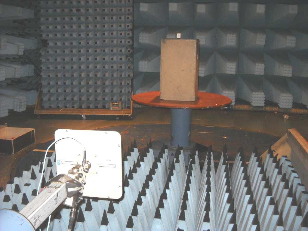
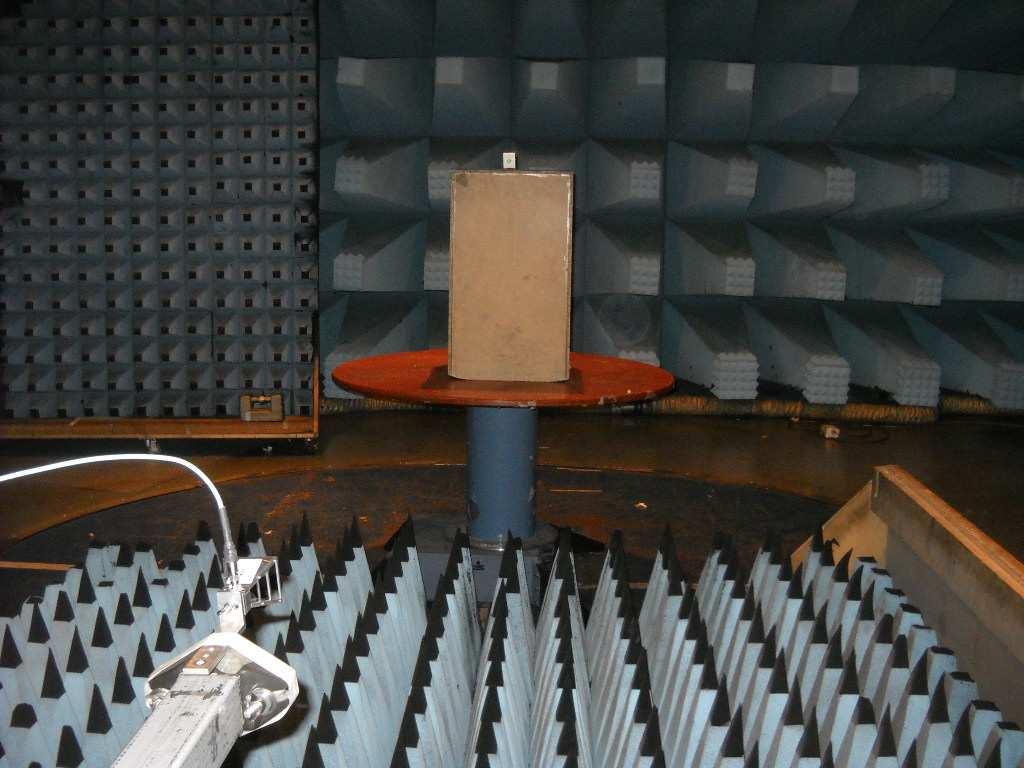
77 8.8 Setup photos Report reference ID: TRFFCC Page 77 of 80
78 Section 9: Block diagrams of test set-ups Section 9: Block diagrams of test set-ups Radiated emissions set-up below 1 GHz Report reference ID: TRFFCC Page 78 of 80


79 Section 9: Block diagrams of test set-ups Radiated emissions set-up above 1 GHz Radio absorbing material Test antenna Antenna mast 4 m 3 m 1.5 m EUT Nonconducting table Test antenna 1 m Metal ground plane Turn table Receiver RF pre-amp Conducted emissions set-up Report reference ID: TRFFCC Page 79 of 80


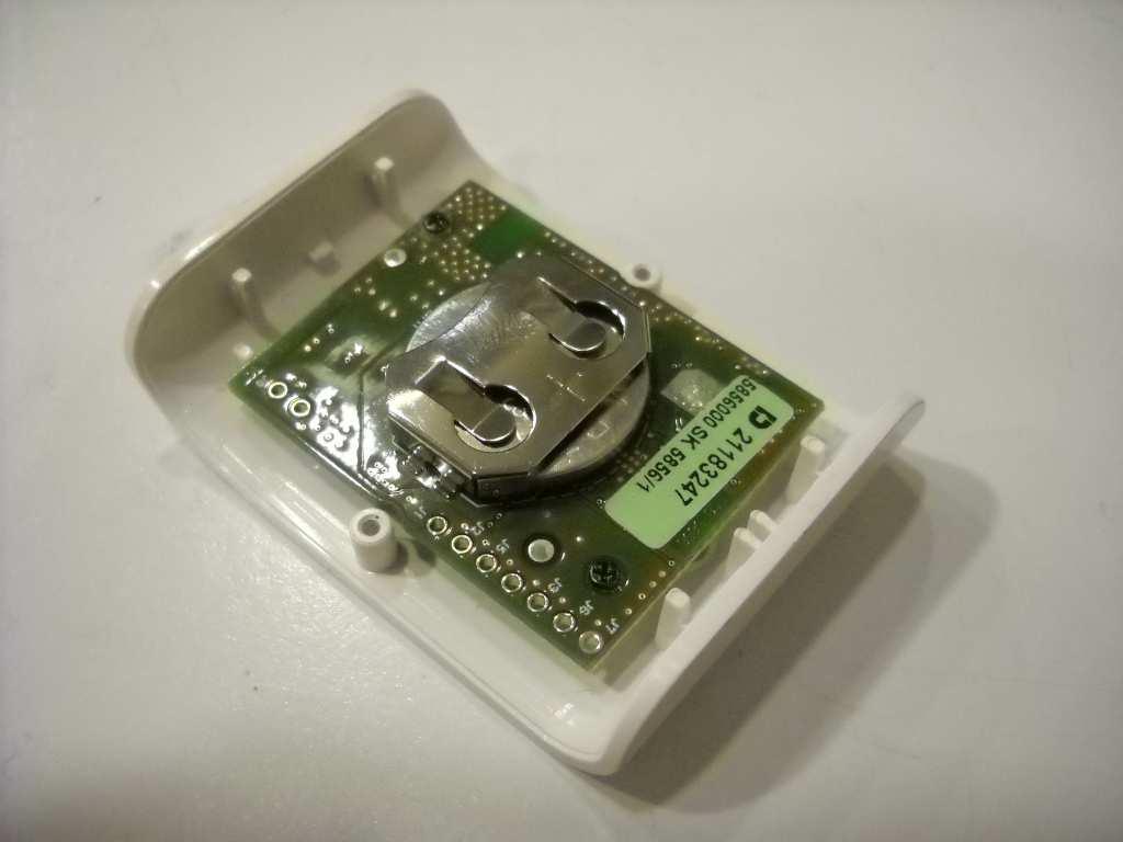
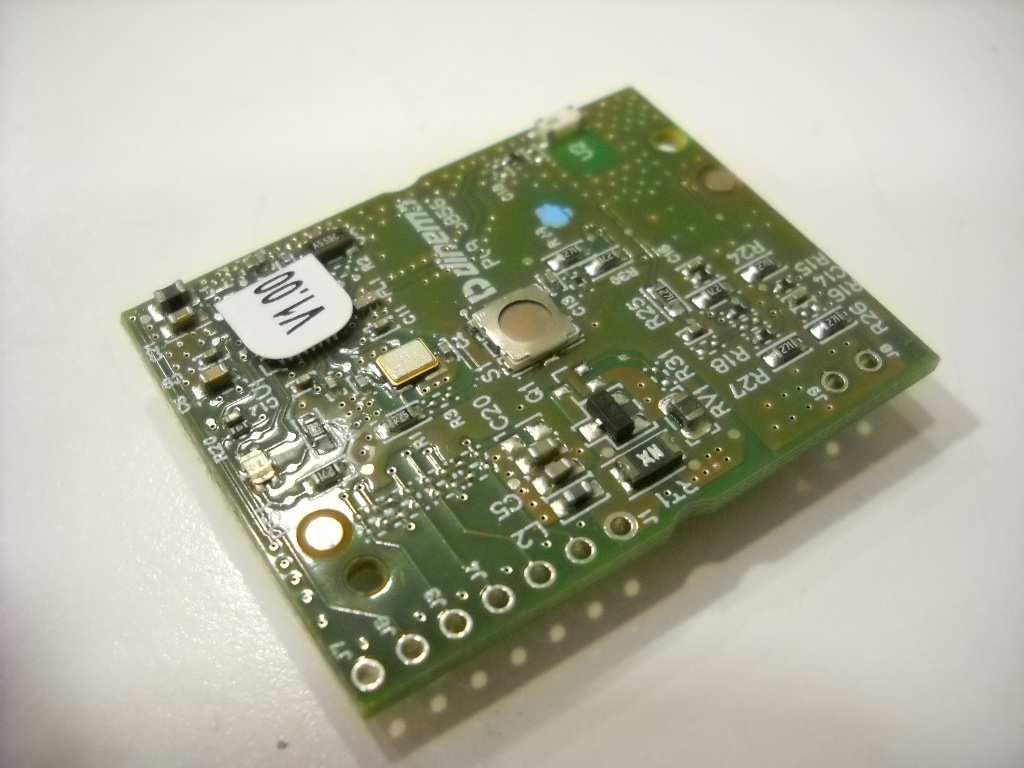
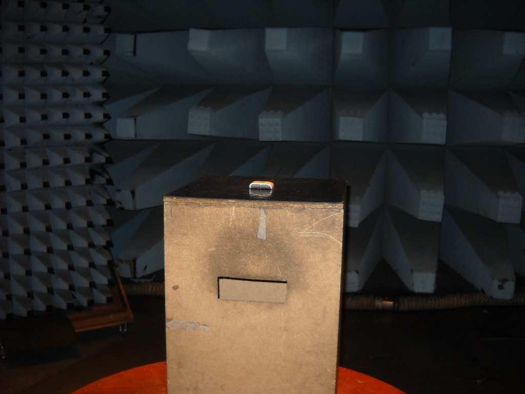
80 Section 10: EUT photos Section 10: EUT photos Report reference ID: TRFFCC Page 80 of 80
Chapter I - Federal Communications Commission Subchapter A - General Part 15 - Radio Frequency Devices Subpart C - Intentional Radiators
 www.nemko.com Report Reference ID 167484-1TRFWL Test specification Title 47 - Telecommunication Chapter I - Federal Communications Commission Subchapter A - General Part 15 - Radio Frequency Devices Subpart
Operation in the MHz, MHz, and MHz
 ONE WORLD OUR APPROVAL Test report 325284-1R2TRFWL Date of issue: June 22, 2017 Applicant: SMART Technologies Product: PEN ID Model: SBID-7000-PEN FCC ID: QCI7PEN IC Registration number: 4302A-7PEN Specifications:
Revision history. Revision Date of issue Test report No. Description KES-RF-14T0042 Initial
 Page (2 ) of (34) Revision history Revision Date of issue Test report No. Description - 2014.08.25 Initial Page (3 ) of (34) TABLE OF CONTENTS 1. General information... 4 1.1. EUT description... 4 1.2.
TEST REPORT Title 47-Telecommunication
 TEST REPORT Title 47-Telecommunication Chapter I - Federal Communications Commission Subchapter A - General Part 5 - Radio Frequency Devices Subpart B - Unintentional Radiators Report Reference No....
D. Guarnone (verifier)
") TEST REPORT Title 47-Telecommunication Chapter I - Federal Communications Commission Subchapter A - General Part 15 - Radio Frequency Devices Subpart B - Unintentional Radiators Report Reference No....354297-4TRFFCC
TEST REPORT Title 47-Telecommunication Chapter I - Federal Communications Commission Subchapter A - General Part 15 - Radio Frequency Devices Subpart B - Unintentional Radiators Report Reference No....354297-4TRFFCC
FCC and RSS-247 BLE Arris XG1v4 #324689
 ONE WORLD OUR APPROVAL Test report FCC-15.247 and RSS-247 BLE Arris XG1v4 #324689 Date of issue: February 17, 2017 Applicant: ARRIS GROUP INC Product: 4K Set Top Box Model AX014ANM Variants AX014ANC FCC
TRFWL. Autostart Inc Rue Paré Mont-Royal, Québec Canada, H4P 2M2 EZSNAH2503
 Nemko Test Report: 109054-1TRFWL Applicant: Autostart Inc. 5764 Rue Paré Mont-Royal, Québec Canada, H4P 2M2 Apparatus: ASRA 2503 FCC ID: EZSNAH2503 In Accordance With: FCC Part 15 Subpart B, 15.107 and
TABLE OF CONTENTS 1. GENERAL INFORMATION... 4
 TABLE OF CONTENTS 1. GENERAL INFORMATION... 4 1.1. EUT DESCRIPTION... 4 1.2. TEST STANDARDS AND RESULTS... 5 1.3. FACILITIES AND ACCREDITATIONS... 6 1.3.1. FACILITIES... 6 1.3.2. TEST ENVIRONMENT CONDITIONS...
FCC CERTIFICATION TEST REPORT
 Report No:DDT-RE120176 Issued Date: 2013/01/05 FCC CERTIFICATION TEST REPORT FOR Applicant : AliMed Inc. Address : 297 High St Dedham Ma 02026 Equipment under Test : Alert transmitter Model No : #712716
7. Transmitter Radiated Spurious Emissions and Conducted Spurious Emission
 7. Transmitter Radiated Spurious Emissions and Conducted Spurious Emission 7.1 Test Setup Refer to the APPENDIX I. 7.2 Limit According to 15.247(d), in any 100 khz bandwidth outside the frequency band
Page 1 of 51 Report No.: T TEST REPORT FCC ID: 2AGJ5WAP-30. In Accordance with: FCC PART 15, SUBPART C : 2015 (Section 15.
 Page 1 of 51 Report No.: T1851663 01 TEST REPORT FCC ID: 2AGJ5WAP-30 Applicant Address : Gonsin Conference Equipment Co., Ltd : No.401-406,Block C, Idea Industry Park, No.41 Fengxiang Road, Shunde, Foshan,
Test report TRFWL. Lotek Wireless Inc. SRX800 SRX A-SRX800. RSS-215 Issue 2, June Date of issue: July 11, 2014.
 ONE WORLD OUR APPROVAL Test report 250123-2TRFWL Date of issue: July 11, 2014 Applicant: Lotek Wireless Inc. Product: SRX800 Model: SRX800 IC Registration number: 4272A-SRX800 Specification: RSS-215 Issue
FCC ID: B4OCC264BPA-S
 FCC TEST REPORT FCC ID: B4OCC264BPA-S Product : Bluetooth LE Module Model Name : CC264BPA-S, CC265BPA-S, CC26xBPA Brand : GT-tronics Report No. : PTC801181160622E-FC01 Prepared for GT-tronics HK Ltd Unit
[ Contents ] KCTL-TIR /0. Report No.: KCTL16-SFR0039
![[ Contents ] KCTL-TIR /0. Report No.: KCTL16-SFR0039](/thumbs/95/123514171.jpg "[ Contents ] KCTL-TIR /0. Report No.: KCTL16-SFR0039") [ Contents ] 1. Client information... 3 2. Laboratory information... 4 3. Description of E.U.T.... 5 3.2 General description... 5 3.3 Test frequency... 6 3.4 Test Voltage... 6 4. Summary of test results...
[ Contents ] 1. Client information... 3 2. Laboratory information... 4 3. Description of E.U.T.... 5 3.2 General description... 5 3.3 Test frequency... 6 3.4 Test Voltage... 6 4. Summary of test results...
Test Report Version. Test Report No. Date Description. DRTFCC Sep. 12, 2014 Initial issue
 DEMC1407-02828 FCC ID: 2AAAQH660W Test Report Version Test Report No. Date Description DRTFCC1409-1165 Sep. 12, 2014 Initial issue Page 2 DEMC1407-02828 FCC ID: 2AAAQH660W Table of Contents 1. EUT DESCRIPTION...
For. Tzone FCC ID: FCC Part Description: Product TZ-BT04. Report to Tested By: Manager STR I
 FCCC Part 15C Measurement and Test For Report Tzone Digitall Technology Co.., LTD 16D, Haiying Building, South of Caitian Road, Futiann District, Shenzhen China FCC ID: 2AKSQTZBT04 FCC Rule(s): Product
FCC CFR47 PART 15 SUBPART C INDUSTRY CANADA RSS-GEN AND RSS-210 CERTIFICATION TEST REPORT FOR BROADCOM BLUETOOTH MODULE MODEL NUMBER: BCM92046MD
 FCC CFR47 PART 15 SUBPART C INDUSTRY CANADA RSS-GEN AND RSS-210 CERTIFICATION TEST REPORT FOR BROADCOM BLUETOOTH MODULE MODEL NUMBER: BCM92046MD IC #: 4324A-BRCM1029 REPORT NUMBER: 07U11199-1C ISSUE DATE:
TEST REPORT FCC ID: 2ADMF-HC06. : bluetooth module keyes HC-06, keyes hc-05, FUNDUINO HC-06, FUNDUINO hc-05
 Shenzhen Certification Technology Service Co., Ltd. 2F, Building B, East Area of Nanchang Second Industrial Zone, Gushu 2 nd Road, Bao'an District, Shenzhen 518126, P.R. China TEST REPORT FCC ID: 2ADMF-HC06
FCC 47 CFR PART 15 SUBPART C CERTIFICATION TEST REPORT FOR. Bluetooth Remote Control for Video Set Top Box MODEL NUMBER: IPRC1000 FCC ID: 2ABTE-L3YJC9
 FCC 47 CFR PART 15 SUBPART C CERTIFICATION TEST REPORT FOR Bluetooth Remote Control for Video Set Top Box MODEL NUMBER: IPRC1000 REPORT NUMBER: 15U22448-E1V4 ISSUE DATE: 3/7/2016 Prepared for Verizon Online
FCC 47 CFR PART 15 SUBPART C INDUSTRY CANADA RSS-210 ISSUE 8 BLUETOOTH LOW ENERGY CERTIFICATION TEST REPORT FOR. 2.4GHz LE MODULE MODEL NUMBER: RN4020
 FCC 47 CFR PART 15 SUBPART C INDUSTRY CANADA RSS-210 ISSUE 8 BLUETOOTH LOW ENERGY CERTIFICATION TEST REPORT FOR 2.4GHz LE MODULE MODEL NUMBER: RN4020 REPORT NUMBER: 14U17191-1 ISSUE DATE: MARCH 21, 2014
FCC Report for Parts ,
 FCC Report for Parts 15.247, 15.7 Product name Applicant FCC ID : WSN Node : Evalan : 2AK2M-EVAWSN-N15 Test report No. : 1100161 Ver 1.00 Laboratory information Accreditation Telefication is designated
FCC CFR47 PART 15 SUBPART C INDUSTRY CANADA RSS-247 ISSUE 1 BLUETOOTH LOW ENERGY CERTIFICATION TEST REPORT FOR
 FCC CFR47 PART 15 SUBPART C INDUSTRY CANADA RSS-247 ISSUE 1 BLUETOOTH LOW ENERGY CERTIFICATION TEST REPORT FOR WLAN 2X2 MIMO 802.11a/b/g/n/ac with BLUETOOTH MODEL NUMBER: P2180 REPORT NUMBER: 15U21878-E2V1
Table of Contents 1. GENERAL INFORMATION SYSTEM TEST CONFIGURATION CONDUCTED EMISSIONS TEST RADIATED EMISSION TEST...
 Table of Contents 1. GENERAL INFORMATION... 4 1.1 PRODUCT DESCRIPTION FOR EQUIPMENT UNDER TEST... 4 1.2 RELATED SUBMITTAL(S) / GRANT (S)... 7 1.3 TEST METHODOLOGY... 7 1.4 EQUIPMENT MODIFICATIONS... 7
XBee Series 2 OEM RF Module Model No.: XBEE2 FCC ID: OUR-XBEE2. Applicant: MaxStream, Inc. 355 South 520 West Suite 180 Lindon, UT 84042
 XBee Series 2 OEM RF Module Model No.: XBEE2 Applicant: MaxStream, Inc. 355 South 520 West Suite 180 Lindon, UT 84042 In Accordance With Federal Communications Commission (FCC) Part 15, Subpart C, Section
Title: Test on 5.8 GHz Band Outdoor WiFi (802.11b/g) Wireless Base Station
 Wireless Base Station") Page 20 of 51 Pages 7.5. Conducted spurious emission 7.5.1. Requirements: Clause 15.247(d). In any 100 khz bandwidth outside the frequency band in which the spread spectrum or digitally modulated intentional
Page 20 of 51 Pages 7.5. Conducted spurious emission 7.5.1. Requirements: Clause 15.247(d). In any 100 khz bandwidth outside the frequency band in which the spread spectrum or digitally modulated intentional
Test Report Version. Test Report No. Date Description. DRTFCC Jan. 13, 2015 Initial issue
 Test Report Version Test Report No. Date Description DRTFCC1501-0004 Jan. 13, 2015 Initial issue TRF-RF-219(00)130701 Page2 / 37 Table of Contents 1. GENERAL INFORMATION... 4 2. EUT DESCRIPTION... 4 2.1
EMC Test Report. Tested by: Jeremy O. Pickens, Senior EMC Engineer. Reviewed by: David Schramm, EMC/RF/SAR/HAC Manager
 Page: 1 of 24 EMC Test Report Project Number: 4104971 Report Number: 4104971EMC01 Revision Level: 0 Client: Tier One, Inc. Equipment Under Test: GEN4 Glock Sensor Model Number: BA10232 FCC ID: 2AJ3810232
Medtronic MiniMed TEST REPORT FOR. GST3 Glucose Sensor Transmitter, MMT-7763A. Tested To The Following Standards:
 Medtronic MiniMed TEST REPORT FOR GST3 Glucose Sensor Transmitter, MMT-7763A Tested To The Following Standards: FCC Part 15 Subpart C Sections 15.247 Date of issue: October 31, 2013 This test report bears
SHENZHEN LCS COMPLIANCE TESTING LABORATORY LTD. FCC ID: 2ADPC-G6 Report No.: LCS E
 2) Sequence of testing 30 to 1 GHz Setup: --- The equipment was set up to simulate a typical usage like described in the user manual or described by manufacturer. --- If the EUT is a tabletop system, a
ITL Page 2 of 71 Report No.:
 ITL Page 1 of 71 Report No.: 12092752 TEST REPORT Applicant: Address of Applicant: Harman International Industries, Incorporated 8500 Balboa Blvd, Northridge, CA 91329, United States Manufacturer: Address
REPORT REVISION HISTORY...
 Reference No.: WTS17S0579239E Page 2 of 39 2 Contents Page 1 COVER PAGE... 1 2 CONTENTS... 2 3 REPORT REVISION HISTORY... 3 4 GENERAL INFORMATION... 4 4.1 GENERAL DESCRIPTION OF E.U.T.... 4 4.2 DETAILS
FCC PART TEST REPORT. Weccan Industrial Limited
 FCC PART 15.249 TEST REPORT For Weccan Industrial Limited Rm209, 2/F, Building W1-A, No.34 Gaoxin South 4th St Hi-Tech Industrial Park, Nanshan District, Shenzhen China FCC ID: Z3CWECCANDRONE Report Type:
FCC RF TEST REPORT No SHA-001
 Page 1 of 41 FCC RF TEST REPORT No. 180300344SHA-001 Applicant : Stanley Black & Decker, Inc. 400 Executive Blvd S, Southington, CT 06489 USA Manufacturer : Northwest Instrument Inc. 330 Waterloo Valley
EMI T E S T R E P O R T
 EMI T E S T R E P O R T - FCC Part 15.249, RSS210 - Test Report No. : T36940-00-00TK 27. August 2013 Date of issue Type / Model Name : PRA30 Product Description : Radio remote control for Laser detector
FCC AND IC CERTIFICATION TEST REPORT
 Issued Date: Mar. 8, 205 FCC AND IC CERTIFICATION TEST REPORT FOR Applicant : Harman International Industries, Incorporated Address : 8500 Balboa Blvd, Northridge, CA 9329, UNITED STATES Equipment under
FCC REPORT. 570 E1 Camino Real #200, Redwood City, CA 94063, United Manufacturer:
 FCC REPORT Applicant: Address of Applicant: Manufacturer: Striiv Inc. 570 E1 Camino Real #200, Redwood City, CA 94063, United States Striiv Inc. Address of 570 E1 Camino Real #200, Redwood City, CA 94063,
FCC PART 15C & RSS 247 TEST REPORT
 FCC PART 15C & RSS 247 TEST REPORT No. I18N01184-WLAN for Spectralink Corp GSM Quad-band/UMTS five-band/lte/ca Mobile phone 9640 with Hardware Version: PIO Software Version: vf03 FCC ID: IYG96XX IC: 2128B-96XX
Ave output power ANT 1(dBm) Ave output power ANT 2 (dbm)
 Ave output power ANT 2 (dbm)") Page 41 of 103 9.6. Test Result The test was performed with 802.11b Channel Frequency (MHz) power ANT 1(dBm) power ANT 2 (dbm) power ANT 1(mW) power ANT 2 (mw) Limits dbm / W Low 2412 7.20 7.37 5.248 5.458
Page 41 of 103 9.6. Test Result The test was performed with 802.11b Channel Frequency (MHz) power ANT 1(dBm) power ANT 2 (dbm) power ANT 1(mW) power ANT 2 (mw) Limits dbm / W Low 2412 7.20 7.37 5.248 5.458
7. FREQUENCY SEPARATION
 7. FREQUENCY SEPARATION 7.1. Limits According to FCC Section 15.247(a)(1), Frequency hopping systems shall have hopping channel carrier frequencies separated by a minimum of 25 khz or two-thirds of the
TEST REPORT : 2AIB7MGS. TEST DATE : to
 TEST REPORT APPLICANT : Hohem Technology Co.,Ltd PRODUCT NAME : 3-Axis Stabilizing Gimbal for Smartphone MODEL NAME BRAND NAME FCC ID STANDARD(S) : isteady Mobile : Hohem : 2AIB7MGS : 47 CFR Part 15 Subpart
FCC REPORT. Dongguan Hele Electronics Co.,Ltd. * In the configuration tested, the EUT complied with the standards specified above.
 Report No.: GTS201708000040F02 FCC REPORT Applicant: Address of Applicant: Manufacturer: Dongguan Hele Electronics Co.,Ltd. Dalingya Industrial Zone,Daojiao Town,Dongguan City,Guangdong,China Dongguan
Application for Grant of Equipment Authorization of the SMK Electronics Corp. RC04 RF Remote Control
 America Report On Application for Grant of Equipment Authorization of the SMK Electronics Corp. RC04 RF Remote Control FCC Part 15 Subpart C 15.247 IC RSS-Gen and RSS-210 Issue 8 December 2010 September
Test Report Version. Test Report No. Date Description. DRTFCC Sep. 17, 2014 Initial issue. DEMC Report No.
 FCCID: 2AALG-NWP-F110 Test Report Version Test Report No. Date Description DRTFCC1409-1176 Sep. 17, 2014 Initial issue Page2 / 33 FCCID: 2AALG-NWP-F110 Table of Contents 1. GENERAL INFORMATION... 4 2.
Pico 900MHz 1W FHSS Module Model: p900 FCC ID: NS913P900. Applicant:
 Pico 900MHz 1W FHSS Module Model: p900 Applicant: Microhard Systems Inc. 150 Country Hills Landing NW Calgary, Alberta Canada T3K 5P3 In Accordance With Federal Communications Commission (FCC) Part 15,
Test Report of FCC CFR 47 Part 15 Subpart C
 Test Report of FCC CFR 47 Part 15 Subpart C On Behalf of GL Technologies (Hong Kong) Limited Unit 210D, 2/F, Enterprise Place Hong Kong Science Park, Shatin, N.T, Hong Kong Product Name: Model/Type No.:
TEST REPORT. Issued for: ShenZhen MYGT Co.,LTD D3 Tongfuyu Industrial Area Community of Shajing Town, Baoan, Shenzhen, China.
 TEST REPORT FCC ID: 2AMKEMY-C11 Product: Wireless Gamepad Model No.: MY-C11 Additional Model No.: TKGC01 Trade Mark: N/A Issued Date: Oct. 16, 2017 Issued for: ShenZhen MYGT Co.,LTD D3 Tongfuyu Industrial
RADIO TEST REPORT. For Shenzhen ZD Intelligent Technology Co., Ltd.
 RADIO TEST REPORT For Shenzhen ZD Intelligent Technology Co., Ltd. Product Name: WIFI Camera Model : WXHI130W-V11 WXHI100W-V8 WXHI100W-V9 WXHI100W-V10 ZD-CHI130B-F3 Series Model: ZD-HGM130B-F2 ZD-CHI130B-F4
Description of Test Facility
 Description of Test Facility Name: Address: Intertek Testing Services Limited Shanghai Building No.86, 1198 Qinzhou Road(North), Shanghai 200233, P.R. China FCC Registration Number: 236597 IC Assigned
RF TEST REPORT for Intentional Radiator No SHA-001
 RF TEST REPORT for Intentional Radiator No. 160600514SHA-001 Applicant : Shanghai Ruipai Intelligent Technology Co.,Ltd. B105, Building 9, Wusong Science Park, No.69 Tieshan Rd., Baoshan District, Shanghai,
ACCORDING TO: FCC part 15 subpart C, and subpart B FOR:
 Electrical Hermon Laboratories Ltd. P.O.Box 23, Binyamina 30500, Israel Tel. +972 4628 8001 Fax. +972 4628 8277 E-mail: mail@hermonlabs.com TEST REPORT ACCORDING TO: FCC part 15 subpart C, 15.247 and subpart
EUROFINS PRODUCT SERVICE GMBH. FCC RULES PARTS IC RADIO STANDARDS RSS-210 Issue 7 FCC ID: UOU68981AA630D-01 IC: 1884E
 EUROFINS PRODUCT SERVICE GMBH TEST - REPORT FCC RULES PARTS 15.247 IC RADIO STANDARDS RSS-210 Issue 7 FCC ID: UOU68981AA630D-01 IC: 1884E-68981000 Model Name: Aastra 630d Test report no.: G0M20811-2089-P-15
FCC PART & IC RSS GHz FHSS TEST REPORT
 FCC PART 15.247 & IC RSS-247 2.4 GHz FHSS TEST REPORT 849 NW State Road 45 Newberry, FL 32669 USA Ph.: 888.472.2424 or 352.472.5500 Fax: 352.472.2030 Email: info@timcoengr.com Website: www.timcoengr.com
TEST REPORT. For RFID READER/WRITER. In conformity with. FCC CFR 47 Part15 Subpart C
 TEST REPORT For RFID READER/WRITER In conformity with FCC CFR 47 Part15 Subpart C Model: TR3XM-SD01 / TR3XM-SU01 / TR3XM-SN01 FCC ID: MK4TR3XM-SX01 Test Item: RFID READER/WRITER Report No: RY1203Z12R1
FCC & RSS-216 (Class II Permissive Change) Wireless Power Transfer Report. for A Acer Incorporated
 Wireless Power Transfer Report. for A Acer Incorporated") Page 1 of 17 FCC 15.209 & RSS-216 (Class II Permissive Change) Wireless Power Transfer Report for A Acer Incorporated 8F., No.88, Sec. 1, Xintai 5th Rd., Xizhi, New Taipei City 22181, Taiwan (R.O.C) Product
Page 1 of 17 FCC 15.209 & RSS-216 (Class II Permissive Change) Wireless Power Transfer Report for A Acer Incorporated 8F., No.88, Sec. 1, Xintai 5th Rd., Xizhi, New Taipei City 22181, Taiwan (R.O.C) Product
Report No.: BST Y ER 2 RADIO TEST REPORT. For Shenzhen sinocam Technology Co.,LTD.
 RADIO TEST REPORT For Shenzhen sinocam Technology Co.,LTD. Product Name: WIFI IP CAMERA Model : Series Model: FCC ID: SN IPC HW01 SN IPC HW01, SN IPC HW02, SN IPC HW03, SN IPC HW04, SN IPC HW05, SN IPC
AN4949 Application note
 Application note Using the S2-LP transceiver under FCC title 47 part 15 in the 902 928 MHz band Introduction The S2-LP is a very low power RF transceiver, intended for RF wireless applications in the sub-1
FCC REPORT. Dongguan Hele Electronics Co.,Ltd. * In the configuration tested, the EUT complied with the standards specified above.
 + Applicant: Address of Applicant: Manufacturer: FCC REPORT Dongguan Hele Electronics Co.,Ltd. Report No.: GTS201708000040F01 Dalingya Industrial Zone,Daojiao Town,Dongguan City,Guangdong,China Dongguan
Report On. Application for Grant of Equipment Authorization of the Hunter Douglas Window Fashions PV HUB Bluetooth Window Blind Remote Control
 America Report On Application for Grant of Equipment Authorization of the Hunter Douglas Window Fashions PV HUB Bluetooth Window Blind Remote Control FCC Part 15 Subpart C 15.247: 2014 IC RSS Gen Issue
APPLICATION CERTIFICATION FCC Part 15C&RSS-247 On Behalf of Sunwoda Electronic Co., Ltd. Active stylus. Model No.: SPEN-HP-03
 Page 1 of 59 APPLICATION CERTIFICATION FCC Part 15C&RSS-247 On Behalf of Sunwoda Electronic Co., Ltd. Active stylus Model No.: SPEN-HP-03 FCC ID: 2ABWESPEN-HP-03 IC: 23012-SPENHP03 Prepared for : Sunwoda
FCC ID: 2ALT5-GW6088
 TEST REPORT FCC ID: 2ALT5-GW6088 For GREAT WORLD LTD Electric Heater Model No. : GW-6078TBT, GW-6088TBT, GW-5088C-AMBT, GW-6088TMBT Trade Name : N/A Prepared for : Address : GREAT WORLD LTD 406 Room 1,
Test Report Version. Test Report No. Date Description
 Test Report Version Test Report No. Date Description DRTFCC1610-0133 Oct. 06, 2016 Initial issue TRF-RF-237(02)160407 Prohibits the copying and re-issue of this report without DT&C approval. Pages: 2 /
Quality Auditing Institute # Schoolhouse Street, Coquitlam, BC, V3K 4X9, Canada. ISO Accreditation:
 CANADA: 16-211 Schoolhouse Street Coquitlam, British Columbia Canada V3K 4X9 ELECTROMAGNETIC COMPATIBILITY TEST REPORT TO CFR 47 FCC Part 15, Subpart C, Section 15.225 Industry Canada RSS 210, Issue 8
APPLICATION FOR CERTIFICATION On Behalf of Futaba Corporation Radio Control Model No.:T10CG-2.4G FCC ID:AZPT10CG-24G Brand : Futaba
 FCC ID. AZPT10CG-24G Page 1 of 56 APPLICATION FOR CERTIFICATION On Behalf of Futaba Corporation Radio Control Model No.:T10CG-2.4G FCC ID:AZPT10CG-24G Brand : Futaba Prepared for : Futaba Corporation 1080
EMI T E S T R E P O R T
 EMI T E S T R E P O R T - FCC Part 15B - Test Report No. : T38935-00-02TK 27. November 2014 Date of issue Type / Model Name : One Touch Select Plus Flex Product Description : Blood glucose meter with Bluetooth
TABLE OF CONTENTS 1 ADMINISTRATIVE DATA (GENERAL INFORMATION) Identification of the Testing Laboratory... 5
 Identification of the Testing Laboratory... 5") Revision History Version Issue Date Revisions Content Rev. 01 May 25, 2018 Initial Issue Rev. 02 May 29, 2018 Added the test software in Equipment lists in section 4.2; Corrected the description of EIRP
Revision History Version Issue Date Revisions Content Rev. 01 May 25, 2018 Initial Issue Rev. 02 May 29, 2018 Added the test software in Equipment lists in section 4.2; Corrected the description of EIRP
Federal Communications Commission Office of Engineering and Technology Laboratory Division
 April 9, 2013 Federal Communications Commission Office of Engineering and Technology Laboratory Division Guidance for Performing Compliance Measurements on Digital Transmission Systems (DTS) Operating
Measurement of Digital Transmission Systems Operating under Section March 23, 2005
 Measurement of Digital Transmission Systems Operating under Section 15.247 March 23, 2005 Section 15.403(f) Digital Modulation Digital modulation is required for Digital Transmission Systems (DTS). Digital
FCC 47 CFR PART 15 SUBPART C
 FCC 47 CFR PART 15 SUBPART C Product Type Applicant Address Trade Name Model Number : Wink Relay : Quirky, Inc. : 606 W 28th St, Floor 7 New York NY 10001 United States : Wink : PRLAY-WH01 Test Specification
A Test Lab Techno Corp. Report Number:1410FR27
 Mode 5: IEEE 802.11n 2.4GHz 40MHz Link Mode 2422 2437 2452 Page 41 of 85 9 Out of Band Conducted Emissions Measurement 9.1. Limit In any 100 khz bandwidth outside the frequency band in which the spread
TEST REPORT FROM RFI GLOBAL SERVICES LTD
 FROM RFI GLOBAL SERVICES LTD Test of: CIBS To: FCC Part 15.247: 2008 Subpart C, RSS-210 Issue 7 June 2007 & RSS-Gen Issue 2 June 2007 Test Report Serial No: RFI/RPT2/RP75103JD05A Supersedes Test Report
FCC & IC TEST REPORT for Bluetooth Device No SHA-001
 Page 1 of 41 FCC & IC TEST REPORT for Bluetooth Device No. 161100632SHA-001 Applicant : Manufacturer : Product Name : SHENZHEN DNS INDUSTRIES CO., LTD. 23/F Building A, Shenzhen International Innovation
TEST REPORT. Report Number: MIN-001 Rev 1.1 Project Number: G Testing performed on the 2102 IPG
 TEST REPORT Report Number: 100511823MIN-001 Rev 1.1 Project Number: G100511823 Testing performed on the 2102 IPG FCC ID: SVHBAROSTIMIPG1 Industry Canada ID: 9464A-IPG210A to 47 CFR Part 95 Subpart I:2013
TEST REPORT. Reference No... : WTS16S E FCC ID... : SJ8-UDR777HD. Applicant... : RDI Technology Shenzhen Co., Ltd.
 TEST REPORT Reference No.... : WTS16S0449305E FCC ID... : SJ8-UDR777HD Applicant... : RDI Technology Shenzhen Co., Ltd. Address... : Building C1, Xintang Industrial Park East Baishixia, Fuyong, Baoan,
Nemko Canada Inc., 303 River Road, R.R. 5, Ottawa, Ontario, Canada, K1V 1H2
 www.nemko.com Nemko Canada Inc., 303 River Road, R.R. 5, Ottawa, Ontario, Canada, K1V 1H2 Report Number: Product Marketing Name: 123766-1TRFEMC Paycheck 4 Thermal Ticket Printer Test Specification: FCC
Test report TRFWL. Texas Instruments Inc. CC3100 Booster-pack CC3100MODR11MAMOB ETSI EN V1.8.1 ( )
") ONE WORLD OUR APPROVAL Test report 264561-4TRFWL Date of issue: November 20, 2014 Applicant: Texas Instruments Inc. Product: CC3100 Booster-pack Model: CC3100MODR11MAMOB Specifications: ETSI EN 300 328
ONE WORLD OUR APPROVAL Test report 264561-4TRFWL Date of issue: November 20, 2014 Applicant: Texas Instruments Inc. Product: CC3100 Booster-pack Model: CC3100MODR11MAMOB Specifications: ETSI EN 300 328
FCC Test Report. Report No.: AGC FE02 CLIENT : INNOVATIVE CONCEPTS AND DESIGN LLC. Attestation of Global Compliance (Shenzhen) Co., Ltd.
 Co., Ltd.") Page 1 of 43 FCC Test Report Report No.: AGC03588150607FE02 FCC ID : 2AE6GUHF 6000HHM APPLICATION PURPOSE : ORIGINAL EQUIPMENT PRODUCT DESIGNATION : Wireless Microphone BRAND NAME : Gemini MODEL NAME :
Page 1 of 43 FCC Test Report Report No.: AGC03588150607FE02 FCC ID : 2AE6GUHF 6000HHM APPLICATION PURPOSE : ORIGINAL EQUIPMENT PRODUCT DESIGNATION : Wireless Microphone BRAND NAME : Gemini MODEL NAME :
TEST REPORT. Issued for: RUIMA INTERNATIONAL(HK)INDUSTRIAL CO.,LIMITED NO.19 Ruixiang Road, Xinhua Industrial Zone, Huadu District, Guangzhou China
INDUSTRIAL CO.,LIMITED NO.19 Ruixiang Road, Xinhua Industrial Zone, Huadu District, Guangzhou China") TEST REPORT FCC ID: 2AHSJRM-626B Product: Boombox Speaker Model No.: RM-626 Additional Model: STREET HOPPER 6, CANNON 6 Trade Mark: RUIMA Issued Date: Aug. 04, 2016 Issued for: RUIMA INTERNATIONAL(HK)INDUSTRIAL
TEST REPORT FCC ID: 2AHSJRM-626B Product: Boombox Speaker Model No.: RM-626 Additional Model: STREET HOPPER 6, CANNON 6 Trade Mark: RUIMA Issued Date: Aug. 04, 2016 Issued for: RUIMA INTERNATIONAL(HK)INDUSTRIAL
Application Note: Testing for FCC Pre-Compliance with LoRaWAN Modules
 SX1261 WIRELESS & SENSING PRODUCTS Application Note: Testing for FCC Pre-Compliance with LoRaWAN Modules AN1200.42 Rev 1.0 May 2018 www.semtech.com Table of Contents 1. Introduction... 4 2. Results Summary...
TEST REPORT. For. Model Name : Maestro T4HU1608, Maestro T4HUXXXX (X is 0 to 9) Issued by : Most Technology Service Co., Limited.
 Issued by : Most Technology Service Co., Limited.") TEST REPORT For Applicant : Address : Product Name : Tech4home, Lda Rua de Fundoes, No.151, 3700-121 Sao Joao da Madeira, Portugal Remote Control Unit Model Name : Maestro T4HU1608, Maestro T4HUXXXX (X
TEST REPORT For Applicant : Address : Product Name : Tech4home, Lda Rua de Fundoes, No.151, 3700-121 Sao Joao da Madeira, Portugal Remote Control Unit Model Name : Maestro T4HU1608, Maestro T4HUXXXX (X
TABLE OF CONTENTS 1 ADMINISTRATIVE DATA (GENERAL INFORMATION) Identification of the Testing Laboratory... 5
 Identification of the Testing Laboratory... 5") Revision History Version Issue Date Revisions Content Rev. 01 Jun. 26, 2017 Initial Issue TABLE OF CONTENTS 1 ADMINISTRATIVE DATA (GENERAL INFORMATION)... 5 1.1 Identification of the Testing Laboratory...
Revision History Version Issue Date Revisions Content Rev. 01 Jun. 26, 2017 Initial Issue TABLE OF CONTENTS 1 ADMINISTRATIVE DATA (GENERAL INFORMATION)... 5 1.1 Identification of the Testing Laboratory...
Digital Transmission Systems (DTSs), Frequency Hopping Systems (FHSs) and Licence-Exempt Local Area Network (LE-LAN) Devices
, Frequency Hopping Systems (FHSs) and Licence-Exempt Local Area Network (LE-LAN) Devices") Issue 1 2015 Spectrum Management and Telecommunications Radio Standards Specification Digital Transmission Systems (DTSs), Frequency Hopping Systems (FHSs) and Licence-Exempt Local Area Network (LE-LAN)
Issue 1 2015 Spectrum Management and Telecommunications Radio Standards Specification Digital Transmission Systems (DTSs), Frequency Hopping Systems (FHSs) and Licence-Exempt Local Area Network (LE-LAN)
Version TEST REPORT NO. DATE DESCRIPTION
 Version NO. DATE DESCRIPTION HCTR1302FR13 February 14, 2013 - First Approval Report - Additional Model Name Page 2 of 25 Table of Contents 1. GENERAL INFORMATION... 4 2. EUT DESCRIPTION... 4 3. TEST METHODOLOGY...
FCC PART MEASUREMENT AND TEST REPORT FOR. Guangzhou Walkera Technology CO., LTD
 FCC PART 15.249 MEASUREMENT AND TEST REPORT FOR Guangzhou Walkera Technology CO., LTD Taishi Industrial Park, Yuwoto Town, Panyu District, 511475 Guangzhou, China. FCC ID: S29WK-2801PRO Report Concerns:
FCC CFR47 PART 15 SUBPART C INDUSTRY CANADA RSS-210 ISSUE 7 CERTIFICATION TEST REPORT FOR g WIRELESS LAN + BLUETOOTH PCI-E MINI CARD
 FCC CFR47 PART 15 SUBPART C INDUSTRY CANADA RSS-210 ISSUE 7 CERTIFICATION TEST REPORT FOR 802.11g WIRELESS LAN + BLUETOOTH PCI-E MINI CARD MODEL NUMBER: BCM94312HMGB REPORT NUMBER: 09U12439-2 ISSUE DATE:
Test Report. FCC Part 15, Subpart C, Section Industry Canada RSS-210, Issue 7
 Test Report FCC Part 5, Subpart C, Section 5.247 Industry Canada RSS-, Issue 7 Report Number: CWD67-Cert Model: CWD67 Date: March 3, 0 Prepared by: Grace Lin Date: Mar. 3, 0 Grace Lin, Sr. Compliance Engineer
CENTRE OF TESTING SERVICE INTERNATIONAL
 CENTRE OF TESTING SERVICE INTERNATIONAL OPERATE ACCORDING TO ISO/IEC 17025 FCC ID TEST REPORT TEST REPORT NUMBER : CGZ3160706-01168-EF TEST REPORT For FCC ID 47 CFR PART 15 OCT, 2015 Report Reference No....
FCC CFR47 PART 15 SUBPART C CERTIFICATION TEST REPORT FOR PCMCIA RFID READER CARD MODEL NUMBER: MPR6000 FCC ID: NTTWJMPR6XXX REPORT NUMBER: 04U2954-3
 FCC CFR47 PART 15 SUBPART C CERTIFICATION TEST REPORT FOR PCMCIA RFID READER CARD MODEL NUMBER: MPR6000 FCC ID: NTTWJMPR6XXX REPORT NUMBER: 04U2954-3 ISSUE DATE: NOVEMBER 22, 2004 Prepared for WJ COMUNICATIONS
FCC Test Report. Wayne Hsu / Assistant Manager
 FCC Test Report Equipment : Wireless Pedometer/Tracker Brand Name : ASE Group Model No. : M903 Standard : 47 CFR FCC Part 15.247 Operating Band : 2400 MHz 2483.5 MHz FCC Classification : DTS Applicant
CERTIFICATION TEST REPORT
 CERTIFICATION TEST REPORT Report Number. : 16U23813-E3V3 DTS Applicant : Model : FCC ID : IC : EUT Description : Test Standard(s) : APPLE, INC. 1 INFINITE LOOP CUPERTINO, CA 95014, U.S.A A1822 BCGA1822
TEST REPORT FCC PART
 TEST REPORT FCC PART 15.247 Shenzhen CTL Testing Technology Co., Ltd. Tel: +86-755-89486194 E-mail: ctl@ctl-lab.com Report Reference No.... : CTL1805164013-WF02 Compiled by: ( position+printed name+signature)
FCC CFR47 PART 15 SUBPART C INDUSTRY CANADA RSS-247 ISSUE 1 CERTIFICATION TEST REPORT FOR. WLAN 2X2 MIMO a/b/g/n/ac with BLUETOOTH
 FCC CFR47 PART 15 SUBPART C INDUSTRY CANADA RSS-247 ISSUE 1 CERTIFICATION TEST REPORT FOR WLAN 2X2 MIMO 802.11a/b/g/n/ac with BLUETOOTH MODEL NUMBER: P2180 REPORT NUMBER: 15U21878-E3V2 ISSUE DATE: NOVEMBER
FCC Part 22H & 24E Measurement and Test Report
 FCC Part 22H & 24E Measurement and Test Report For Shenzhen Concox Information Technology Co., Ltd Floor 4th, Building B, Gaoxinqi Industrial Park, Liuxian 1st Road, District 67, Bao an, Shenzhen, China
FCC PART TEST REPORT. invoixa
 FCC PART 15.247 TEST REPORT For invoixa 2 rue Maurice Hartman Issy-Les-Moulineaux France FCC ID: ZVS-KTP1 Report Type: Original Report Product Type: KTP1 Test Engineer: Mike Hu Report Number: RSZ150717005-00B
TEST REPORT. Shenzhen, PRC.
 TEST REPORT Reference No.... : WTS16S0449309E FCC ID... : SJ8-UDRC57 Applicant... : RDI Technology Shenzhen Co., Ltd. Address... : Building C1, Xintang Industrial Park East Baishixia, Fuyong, Baoan, Shenzhen,
TRANSMITTER MODEL: KAS-2030M
 Page 1 of 16 FCC PART 15, SUBPART B and C TEST REPORT for TRANSMITTER MODEL: KAS-2030M Prepared for WILDLIFE TECHNOLOGIES 115 WOLCOTT STREET MANCHESTER, NEW HAMPSHIRE 03103 Prepared by: KYLE FUJIMOTO Approved
FCC 47 CFR PART 15 SUBPART C INDUSTRY CANADA RSS-247 ISSUE 1 BLUETOOTH LOW ENERGY CERTIFICATION TEST REPORT FOR
 FCC 47 CFR PART 15 SUBPART C INDUSTRY CANADA RSS-247 ISSUE 1 BLUETOOTH LOW ENERGY CERTIFICATION TEST REPORT FOR CELLULAR PHONE WITH BLUETOOTH AND WLAN RADIOS MODEL NUMBER: A1778 REPORT NUMBER: 16U23328-E2V5
FCC PART 15C TEST REPORT FOR CERTIFICATION On Behalf of. DEI Sales Inc. dba Definitive Technology. Model Number: STUDIO SLIM SUBWOOFER
 FCC PART 15C TEST REPORT FOR CERTIFICATION On Behalf of DEI Sales Inc. dba Definitive Technology 3.1 Home Theater Sound Bar and Wireless Subwoofer System Model Number: STUDIO SLIM SUBWOOFER FCC ID: IPUSTUSLIMSUB
FCC PART 15 SUBPART C TEST REPORT FCC PART
 FCC PART 15 SUBPART C TEST REPORT FCC PART 15.249 Shenzhen CTL Testing Technology Co., Ltd. Tel: +86-755-89486194 Fax: +86-755-26636041 Report Reference No.: CTL1508212421-WF Compiled by: ( position+printed
TABLE OF CONTENTS 1 ADMINISTRATIVE DATA (GENERAL INFORMATION) Identification of the Testing Laboratory... 6
 Identification of the Testing Laboratory... 6") Revision History Version Issue Date Revisions Content Rev. 01 Feb. 2, 2016 Initial Issue TABLE OF CONTENTS 1 ADMINISTRATIVE DATA (GENERAL INFORMATION)... 6 1.1 Identification of the Testing Laboratory...
Revision History Version Issue Date Revisions Content Rev. 01 Feb. 2, 2016 Initial Issue TABLE OF CONTENTS 1 ADMINISTRATIVE DATA (GENERAL INFORMATION)... 6 1.1 Identification of the Testing Laboratory...
MEASUREMENT REPORT FCC PART & IC RSS-247 Bluetooth v4.1
 MRT Technology (Suzhou) Co., Ltd Report No.: 1512RSU00101 Phone: +86-512-66308358 Report Version: V03 Fax: +86-512-66308368 Issue Date: 04-21-2016 Web: www.mrt-cert.com MEASUREMENT REPORT FCC PART 15.247