DPSI V-Match Operating Instructions Version 1.0
|
|
|
- Myrtle Powers
- 5 years ago
- Views:
Transcription
1 Bedienungsanleitung
2 Page 2 of 16

3 Contents 1. Functionality Programming Changing Servo Direction Calibrating Servo Center Calibrating End-Limits Deleting all Programming Additional Hints Adapting several Servos Changing the Model Sequence of Programming Limiting Tuning Range Technical Data Warranty Page 3 of 16
 is programmable for direction, as well as center position and end-limits. Therefore, this servo adapts (\"matches\") to the main servo (MSTR).")
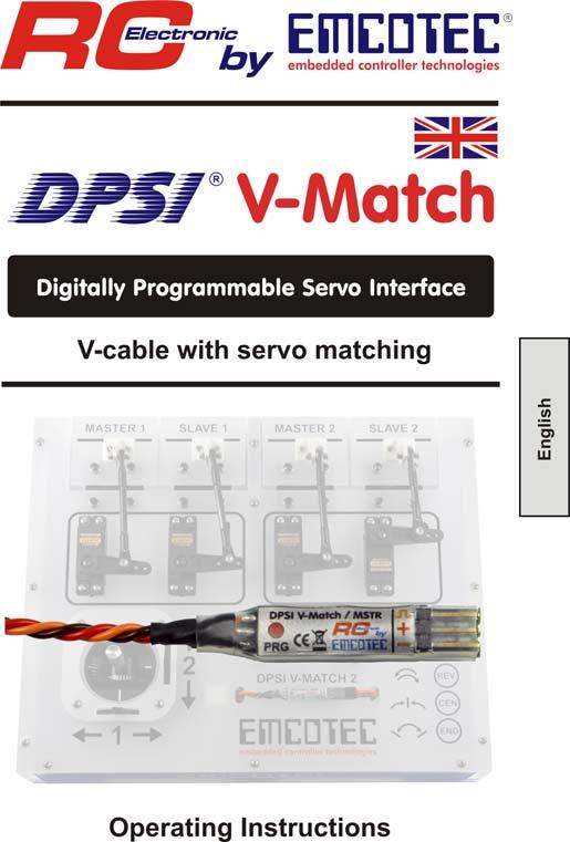
4 1. Functionality DPSI V-Match constitutes a servo V-cable that accommodates two commercially available servos. As a special feature, one servo (SLAVE) is programmable for direction, as well as center position and end-limits. Therefore, this servo adapts ("matches") to the main servo (MSTR). This is especially handy if two servos actuate on one rudder (e.g. two servos on one aileron) and synchronism cannot be established by mechanically means. Often, it suffices if one servo's direction can be changed (e.g. counter rotating mounted servos for the airplane's elevator). This too, is simply accomplished with DPSI V-Match. Failsafe-Function: A failsafe-function is added to its features. Both servos (MSTR and SLAVE) remain at their current position (HOLD) when encountering an erroneous or missing receiver signal until a valid signal is again delivered by the receiver. A flashing red LED (at the PCB's side) indicates this state and stays active (i.e. flashes) until power is turned off. Powerful Servos: The electronically design of the DPSI V-Match allows for usage of powerful digital servos; supply voltage ranging up to 8.4 volts. Due to the PCB (4-layer) and the thick (0.34 mm 2 ) connection cable, current load is especially high. Page 4 of 16

5 Pulse Amplifier & HF-Suppression: Besides pulse amplifiers, which recognize and amplify even weak servo signals, high effective noise filters are built into the DPSI V- Match. Therefore, ferrite cores or other noise suppression measures can be omitted. High Precision: Because of the intelligent software design and a highly accurate crystal oscillator, a resolution of more than 3000 steps is obtained. Therefore, the DPSI V-Match is also suitable for modern remote control systems with high servo positioning precision (number of steps). Page 5 of 16
6 2. Programming There is no external programming device necessary, e.g. a PC or a programming box for programming of the DPSI V-Match. Only a delivered magnet serves for activation of the corresponding programming functions. Everything else is conducted with the transmitter and remote control equipment. During programming, settings of the original servo (master = MSTR) remain unchanged! Programming always refers to the slave servo (SLAVE). Adjustment / programming of the slave servo is only possible within the first 10 seconds after power on. Afterwards, programming is inhibited for safety reasons! Before starting EACH programming, the corresponding transmitter stick (or switch actuator) must be positioned in center position! Hints: If both servos MSTR and SLAVE actuate a common rudder, at least one servo linkage must be released in order to avoid mechanical touch. Whenever a change e.g. of the servo center position takes place, the end-limits should be reprogrammed as well! Basic adjustments in DPSI V-Match correspond to Graupner/JR equipment. Center position is 1.50ms; end-limits are set to 100% each. Of course, all remote control sets can be used with no limitation. Page 6 of 16
 at the DPSI V-Match's side. 2.1. Changing Servo Direction When changing the direction of the servo, all other settings remain!")
7 Whenever programming takes place, the integrated red LED blinks for controlling purposes at a rate of 0.5Hz (1s on, 1s off) at the DPSI V-Match's side Changing Servo Direction When changing the direction of the servo, all other settings remain! For reversing direction of the servo, hold the magnet close to position "PRG" (red dot on sticker) within the first 10 seconds after power on. Distance of the magnet can be up to 8mm. The magnet also operates through thin fuselage sidewalls, if the DPSI V-Match is attached to the fuselage's inner sidewall using e.g. dual adhesive tape. 2.5 seconds after positioning the magnet, the servo makes a short move (10% stroke). If the magnet is removed within the next 5 seconds, the servo direction is reversed and permanently stored. The DPSI V-Match now executes a restart. Page 7 of 16

8 2.2. Calibrating Servo Center Programming also starts by positioning the magnet close to the red dot ("PRG"). The slave servo makes a short move after 2.5 seconds (just like for servo reverse). The magnet now is not removed, but rather remains at the "PRG" position. The stick or switch actuator must not be moved now, i.e. it must remain in center position. After 5 seconds, the servo makes a short move again. Now, programming of servo center is active. The master servo now remains centered and does not move anymore, even if the stick is moved. With each movement of the transmitter stick out of center, the servo position (servo center) is incremented or decremented by one step. If the stick remains in one end-position, steps automatically increment or decrement after 2.5 seconds. This serves for quicker settings of the values. Due to the high resolution of the DPSI V-Match, changes of the servo position are possibly recognizable only after several steps. Page 8 of 16

9 Remove the magnet from its red dot position ("PRG") as soon as the slave servo reaches the desired center position. The DPSI V-Match now starts with the newly programmed center position of the slave servo. Reprogram the end-limits in order to obtain linear curves after programming the servo center Calibrating End-Limits Start programming of end-limits just like programming servo center. Here, the transmitter stick (or switch actuator) is set to maximum position (servo end-limit) within 5 seconds after the servo makes its first short move. After these 5 seconds the servo moves again shortly and both servos remain in their actual (maximum)-position. Reposition the stick to its center position servo positions do not alter! Page 9 of 16
10 Here too, the stroke of the slave servo changes by increasing or decreasing steps when moving the stick out of its center position. Remove the magnet when the desired end position is reached. Whenever changing servo settings, all values should be reprogrammed, i.e. center and end-limits! Sequence of programming (center, end-limits) does not really matter. Attention: Programmable values for end-limits could possibly be higher than the mechanical resolution of the servo. The servo therefore could be damaged or function incorrectly (e.g. wheel spinning) when utilizing the full range. Therefore, approximate the limiting values carefully. An additionally connected servo tester (e.g. using the EMCOTEC Mini Servo Tester part number A71050) can help if in doubt, indicating the corresponding servo position digitally Deleting all Programming Total reset of all programmed settings is possible too. Position the magnet after power on close to the "PRG" position and hold it there for approx. 40 seconds. After 2.5 seconds and after additional 5 seconds the servo makes its short move (just like when programming center/end-limits). The transmitter stick must not be moved at that time and the magnet must remain at the "PRG" position. After 40 seconds have elapsed, all settings are deleted and a restart of the DPSI V-Match takes place. Now, the magnet can be removed. Whenever programming takes place, the integrated red LED blinks for controlling purposes at a rate of 0.5Hz (1s on, 1s off) at the DPSI V-Match's side. Page 10 of 16
 two DPSI V-Match can be chained one after another.")
11 3. Additional Hints These additional hints are valuable for the ambitious user who likes to know more about the functions of the DPSI V-Match by explaining its behavior under certain circumstances Adapting several Servos If more than two servos need to be synchronized (e.g. three aileron servos) two DPSI V-Match can be chained one after another. This means: the input of the second DPSI V-Match connects to the MSTR output of the first DPSI V-Match. Now, a SLAVE output is available at the first DPSI V-Match, a MSTR and a SLAVE output at the second one. Both SLAVE servos can now be independently set up. Page 11 of 16
12 3.2. Changing the Model If a programmed DPSI V-Match is to be used in an other application (e.g. changing a model), generally all settings should be deleted (see also "Deleting all Programming"). This is also true if a servo with a different rotating direction is to be built in Sequence of Programming When programming the slave servo, the rotating direction (if necessary) should always be programmed first. Then center position and end-limits follow, sequence is unimportant. Whenever there is a change, e.g. serve center position, the end-limits should be programmed, too! 3.3. Limiting Tuning Range The DPSI V-Match only allows for certain values when programming or adjusting the slave servo. Because the slave servo is to be adapted to the master servo, both servos should have similar base adjustments in the first place, e.g. comparable center positions. If the center of the master servo already is over 100% of the possible servo stroke it does not make much sense to adjust the slave servo even further. Therefore, only a maximum of +/-100% (referring to JR values) of the servo center position is possible. Adjustment of the slave servo is carried out by a so-called 3-point curve (i.e. center, maximum value left/top, maximum value right/bottom). Page 12 of 16
.")
13 The "distance" of the maximum position of a servo in respect to its center must be at least 20%, otherwise the value is not programmable. Range checking accompanies each programming. It is therefore not possible to position the servo center position off limits. Malfunctions are avoided this way (e.g. V-curve of the servo). Page 13 of 16
14 4. Technical Data Operating Voltage Range 4V V Current Consumption Approx. 4.7mA Servo Signal Level Input: Low-Level 0V V High-Level 2.0V V Servo Signal Level Output: Supplying > 5.1V Approx. 5.0V Supplying < 5.1V Supply voltage -0,1V Maximum Allowable Current 8A continuous, 20A peak Allowable Center Position +/-100% (1.10ms ms) Allowable End-Limits* +/-200% (0.70ms ms) Allowable Signal Cycle Time Min. 6.9ms, max ms Resolution (Steps) 3200 CE-Test According to 2004/108/EC Temperature Range -20 C C HF-Noise Suppression -30dB 35MHz Dimensions approx. 50mm x 8.4mm x 7.2mm Weight Approx. 4.5g Warranty 24 month * Attention: Programmable values for end-limits could possibly be higher than the mechanical resolution of the servo. The servo therefore could be damaged or function incorrectly (e.g. wheel spinning) when utilizing the full range. Therefore, approximate the limiting values carefully. An additionally connected servo tester (e.g. using the EMCOTEC Mini Servo Tester part number A71050) can help if in doubt, indicating the corresponding servo position digitally. Technical modifications and errors excepted! (C) EMCOTEC embedded controller technologies GmbH (P) July 2008 Version 1.0 from July Robert Hussmann Page 14 of 16
15 5. Warranty EMCOTEC GmbH shall issue a 24-month warranty on the DPSI V-Match. The guarantee period shall begin with delivery of the equipment by the retailer and shall be not extended by any guarantee repair or guarantee replacement. During the period of guarantee, the warranty shall cover the repair or replacement of any proven manufacturing or material defects at no charge. There shall be no specific entitlement to repair work. In case of a guarantee claim, the manufacturer shall reserve the right to exchange the equipment for a product of equal value if repair of the item is not feasible for economic reasons. There shall be no assumption of liability for consequential damages that are brought about by a proven defect during operation of the DPSI V-Match. There shall be no extended claims for damages. All transportation, packaging and travel expenses shall be borne by the purchaser. No liability shall be assumed for any damages during transport. If repair is needed, the equipment must be sent to the appropriate service center of the respective country or directly to EMCOTEC GmbH. The guarantee shall only be valid when the following conditions are met: The guarantee document (original invoice) must include the delivery date, the company stamp, the serial number and signature of the retailer. No intervention in the equipment may have been undertaken. It must have been operated in accordance with our operating instructions. Only the power sources and other accessory devices and components that were recommended by us may have been used. The guarantee document (original invoice) and other pertinent information regarding the malfunction (a short description of the defect) must be included with the transmittal. The equipment must still be the property of the initial purchaser. If equipment is sent in that later proves to be functional following an initial inspection, we shall impose a flat processing fee of 15,-. In all other respects, the general business terms and conditions of EMCOTEC embedded controller technologies GmbH shall apply for any items not listed. Page 15 of 16

16 Legal information: Trademarks: The following names are registered trademarks: - EMCOTEC - DPSI - DPSI RV Other product names mentioned in this manual may also be trademarks or registered trademarks of their respective owners. Copyright information: This manual is copyrighted by EMCOTEC GmbH. All rights reserved. This document may not be copied either entirely or in part, nor may it be transferred to any type of medium or translated into any other language without the express written approval of EMCOTEC GmbH. Manual Note: EMCOTEC GmbH reserves the right make changes to this manual and to equipment described herein without notice. Considerable effort has been made to ensure that this manual is free of errors and omissions. We shall not assume responsibility or liability for any errors that may be contained in this manual nor for any incidental, concrete or consequential damage that may arise from the provision of this manual, or the use of this manual in operating the equipment, or in connection with the performance of the equipment when so operated. Page 16 of 16
DPSI LCD Operating Instructions Version 1.0. Contents
 Contents 1. Preface... 3 2. Characteristics... 4 3. Display- and Control-Elements... 6 4. Dimensions... 7 5. Assembly... 8 6. Push-Buttons and LED-Indicators... 9 6.1. Functions of Buttons... 9 6.2. Functions
Table of Contents 9.0 WARRANTY. 1.0 Introduction Package Contents. 2.0 Safety Instructions Overview...003
 9.0 WARRANTY Table of Contents ELECTROMATIC Equipment Co., Inc. (ELECTROMATIC) warrants to the original purchaser that this product is of merchantable quality and confirms in kind and quality with the
LOW NOISE AMPLIFIER LN4000 OPERATING MANUAL THIS AMPLIFIER IS FOR RECEIVER ONLY. DO NOT USE WITH TRANSMITTER!
 LOW NOISE AMPLIFIER LN4000 OPERATING MANUAL THIS AMPLIFIER IS FOR RECEIVER ONLY. DO NOT USE WITH TRANSMITTER! May 18, 2011 1. INTRODUCTION The LN4000 is a high-performance, low-noise wide-band preamplifier
Installation & Operation Manual SAGA1-K Series Industrial Radio Remote Control
 Installation & Operation Manual SAGA1-K Series Industrial Radio Remote Control Gain Electronic Co. Ltd. Table Of Contents Safety Considerations ------------------------------------------------------------2
Model 935A. Dual Tone Sender INSTRUCTION MANUAL
 Model 935A Dual Tone Sender INSTRUCTION MANUAL Monroe Electronics 100 Housel Ave Lyndonville NY 14098 800-821-6001 585-765-2254 fax 585-765-9330 monroe-electronics.com Printed in USA Copyright Monroe Electronics,
Operating Instructions
 Operating Instructions page 2 of 44 Contents 1. Preface... 4 2. Block Diagram DPSI... 5 3. Features... 6 4. The DPSI RV-Family in Headwords... 10 4.1. HFIB (High Frequency Interference Blocking)... 11
AMERITRON RCS-12 AUTOMATIC ANTENNA SWITCH
 AMERITRON RCS-12 AUTOMATIC ANTENNA SWITCH INSTRUCTION MANUAL PLEASE READ THIS MANUAL BEFORE OPERATING THIS EQUIPMENT! 116 Willow Road Starkville, MS 39759 USA 662-323-8211 Version 3B Printed in U.S.A.
RFTX-1 Installation Manual
 RFTX-1 Installation Manual complete control Universal Remote Control RFTX-1 Installation Manual 2009-2014 Universal Remote Control, Inc. The information in this Owner s Manual is copyright protected. No
2001A. 200KHz Function Generator Instruction Manual. 99 Washington Street Melrose, MA Phone Toll Free
 2001A 200KHz Function Generator Instruction Manual 99 Washington Street Melrose, MA 02176 Phone 781-665-1400 Toll Free 1-800-517-8431 Visit us at www.testequipmentdepot.com WARRANTY Global Specialties
WS-7212NU Wireless 433 MHz Weather Station. Instruction Manual
 WS-7212NU Wireless 433 MHz Weather Station Instruction Manual TABLE OF CONTENTS Topic Page Inventory of Contents 3 Additional Equipment 4 Quick Setup Guide 5-9 Function Keys 5 Detailed Set-up Guide 10-15
BC145 SIGNAL ISOLATOR BOARD
 BC145 SIGNAL ISOLATOR BOARD 4/17 Installation & Operating Manual MN1373 Any trademarks used in this manual are the property of their respective owners. Important: Be sure to check www.baldor.com to download
Radio System Strobe Wizard Plus Freemask
 Radio System Strobe Wizard Plus Freemask User manual Translation of the original German user manual Doc. No.: 900.0509.00 Version: 09/2017 Contents Information about this manual and about the manufacturer...
Appearance of device and accessories may vary.
 Mobile 4G Smart Technology Signal Booster Contents: How it Works.... 1 Before Getting Started.... 2 Quick Installation Overview.... 2 Installing the Outside Antenna.... 2 Installing the Low-Profile Antenna....
SSI-4 PLUS User Manual
 SSI-4 PLUS User Manual 1 SSI-4 PLUS... 2 1.1 Getting to Know the SSI-4 PLUS... 2 1.2 Channel Functions... 3 2 Wiring and Setup... 3 2.1 Powering the SSI-4 PLUS... 3 2.2 5V for External Sensors... 4 2.3
MODEL AERONAUTICAL ASSOCIATION OF AUSTRALIA
 ASSOCIATION OF AUSTRALIA ISSUE 5-2002 APPROVED M.A.A.A. PRESIDENT Date: 12/08/2002 Table of Contents 1. Introduction 1 2. General 2 3. Frequency Control and Management 3 3.1 For 40kHz operation 3 3.2 For
A3 Pro INSTRUCTION MANUAL. Oct 25, 2017 Revision IMPORTANT NOTES
 A3 Pro INSTRUCTION MANUAL Oct 25, 2017 Revision IMPORTANT NOTES 1. Radio controlled (R/C) models are not toys! The propellers rotate at high speed and pose potential risk. They may cause severe injury
2012 MFJ ENTERPRISES, INC.
 Model MFJ-9213 INSTRUCTION MANUAL CAUTION: Read All Instructions Before Operating Equipment MFJ ENTERPRISES, INC. 300 Industrial Park Road Starkville, MS 39759 USA Tel: 662-323-5869 Fax: 662-323-6551 VERSION
ATS Elektronik GmbH Manual version 1.04
 MANUAL MTL381 Remote Expander MTM800 FUG / MTM5400 ATS Elektronik GmbH Manual version 1.04 All information in this manual has been compiled after careful investigation, but cannot be considered to be assured
MS23SL Magnetic Linear Sensor With Smart Limit Switches
 MS23SL Magnetic Linear Sensor With Smart Limit Switches 2 micron Quadrature Output 0.4 micron Serial Output 0.4 micron PWM Output Technical Reference Guide PCB Rev 1.0 www.soc-robotics.com Copyright 2013.
Mounting instruction and operating manual. Access Point (UK) HmIP-HAP-UK
 HmIP-HAP-UK") Mounting instruction and operating manual Access Point (UK) HmIP-HAP-UK Package contents Quantity Description 1 Homematic IP Access Point (UK) 1 Plug-in mains adapter 1 Network cable 2 Screws 2 Plugs 1
Mounting instruction and operating manual Access Point (UK) HmIP-HAP-UK Package contents Quantity Description 1 Homematic IP Access Point (UK) 1 Plug-in mains adapter 1 Network cable 2 Screws 2 Plugs 1
Acoustic Emission Preamplifiers Specification
 Acoustic Emission Preamplifiers Specification Released 07-2013 Contact Address Vallen Systeme GmbH Schaeftlarner Weg 26a D-82057 Icking Germany email: info@vallen.de http://www.vallen.de Tel: +49 8178
TABLE OF CONTENTS. Electromatic Equipment Co., Inc. -1-
 TABLE OF CONTENTS 1.0 Introduction 2 1.1 Calibration curves 1.2 Explanation of calibration curves 2.0 Operating the instrument. 3 3.0 View of the instrument. 4 4.0 Menu.. 5 5.0 Other symbols and key functions..
WS-7220U-IT 915 MHz Wireless Weather Station. Instruction Manual
 WS-7220U-IT 915 MHz Wireless Weather Station Instruction Manual 1 TABLE OF CONTENTS Introduction..3 Inventory of Contents 4 Quick Set Up 4 Detailed Set Up 4-5 Battery Installation....4-5 12 or 24 Hour
Contents. English 1. French 29. Spanish. FEATURES: The Temperature Station
 Contents Language Page English 1 French 29 Spanish Topic Page Inventory of Contents 2 Features 3 Setting Up Battery Installation 7 Function keys 9 LCD Screen and Settings 11 Manual Settings 13 Viewing
INSTRUMENTS, INC. Model 2960AX Disciplined Quartz Frequency Standard 2960AX. Section Page Contents
 INSTRUMENTS, INC. Model 2960AX Disciplined Quartz Frequency Standard 2960AX Section Page Contents 1.0............................. 2......................... Description 2.0.............................
UNIVERSAL-DDS-VFO UDV ( 1 Hz to 10 MHz)
") UNIVERSAL-DDS-VFO UDV ( 1 Hz to 10 MHz) Connection and operating instructions 1. Introduction The UDV is the ideal device to adapt older, VFO-controlled transceivers to modern requirements regarding frequency
UNIVERSAL-DDS-VFO UDV ( 1 Hz to 10 MHz) Connection and operating instructions 1. Introduction The UDV is the ideal device to adapt older, VFO-controlled transceivers to modern requirements regarding frequency
dmx2pwm 9 channel dimmer setup manual
 dmx2pwm 9 channel dimmer setup manual www.ecue.de dmx2pwm 9ch dimmer - setup manual e:cue control GmbH An OSRAM Company Rev. 1.2_06/2009 dmx2pwm 9ch dimmer - setup manual table of contents 1. Device Overview....................................
LINCO MEASUREMENT MODEL CP-2B MASTER METER PROVER COUNTER INSTRUCTION MANUAL
 LINCO MEASUREMENT MODEL CP-2B MASTER METER PROVER COUNTER INSTRUCTION MANUAL ENGINEERED AUTOMATED SYSTEMS DESIGNERS ENGINEERS MANUFACTURERS SALES REPRESENTATIVES 4580 W. HWY 80 P.O. BOX 4096 MIDLAND, TEXAS
MFJ SIGNAL ENHANCER II
 MFJ SIGNAL ENHANCER II Model MFJ-752D INSTRUCTION MANUAL CAUTION: Read All Instruction Before Operating Equipment MFJ ENTERPRISES, INC. P.O. BOX 494, MISSISSIPPI STATE, MS 39762, USA 925-0037D-752D-REV
Document Version 1.2
 Document Version 1.2 INTRODUCTION The X-LOAD LB-2 Reactive Load Box is a high-quality passive load box from Fractal Audio Systems. It offers a range of great features including front-panel output level
Si4825-DEMO. Si4825 DEMO BOARD USER S GUIDE. 1. Features. Table 1. Si4825 Band Sequence Definition
 Si4825 DEMO BOARD USER S GUIDE 1. Features ATAD (analog tune and analog display) AM/FM/SW radio Worldwide FM band support 64 109 MHz with 18 bands, see the Table 1 Worldwide AM band support 504 1750 khz
Fiber Optic Expansion Interface
 User Manual for the HE697FBX100 & HE697FBX105 Fiber Optic Expansion Interface Fourth Edition 20 November 1998 MAN0215-04 PREFACE 20 NOV 1998 PAGE 2 PREFACE This manual explains how to use the Fiber Optic
Field Hub Installation Guide. P/N Rev. C 05/15
 Field Hub Installation Guide P/N016-0171-380 Rev. C 05/15 E21714 Copyright 2015 Disclaimer While every effort has been made to ensure the accuracy of this document, Raven Industries assumes no responsibility
ORANGE R610V2 RECEIVER USER MANUAL FEATURES:
 ORANGE R610V2 RECEIVER USER MANUAL FEATURES: Compatible with DSM2 aircraft radio and module systems 6 channel cppm output allowing for single line connection with compatible devices True diversity antennas
Programmable K-Factor Scaler B and Programming Software Kit B
 Programmable K-Factor Scaler B220-885 and Programming Software Kit B220-900 INSTALLATION & INSTRUCTION MANUAL 8635 Washington Avenue Racine, Wisconsin 53406 Toll Free: 800.235.1638 Phone: 262.639.6770
Owner's Manual AM/FM STEREO RADIO WITH AUTO STOP CASSETTE PLAYER. Designed Specifically for the Marine and RV Environment
 Owner's Manual AM/FM STEREO RADIO WITH AUTO STOP CASSETTE PLAYER Designed Specifically for the Marine and RV Environment FACEPLATE CONTROLS DIAGRAM (Figure 1) 1 2 3 4 10 9 8 1 POWER BUTTON Press it to
MODEL FS-4 INSTRUCTION MANUAL R.L. DRAKE COMPANY, MIAMISBURG, OHIO, U.S.A.
 MODEL FS-4 F R E Q U E N C Y S Y N T H E S I Z E R INSTRUCTION MANUAL R.L. DRAKE COMPANY, MIAMISBURG, OHIO, U.S.A. LIMITED WARRANTY R. L. DRAKE COMPANY warrants to the original purchaser that this product
VC-300D VECTRONICS R. Digital Bar Graph Antenna Tuner. Owner's Manual. CAUTION: Read All Instructions Before Operating Equipment!
 VC-300D Digital Bar Graph Antenna Tuner CAUTION: Read All Instructions Before Operating Equipment! VECTRONICS R... the finest amateur radio products made 300 Industrial Park Road Starkville, MS 39759 (662)
PTT- Z or PTT-U PUSH-TO-TALK Specification
 Federal Communication Commission Interference Statement This equipment has been tested and found to comply with the limits for a Class B digital device, pursuant to Part 15 of the FCC Rules. These limits
Parameter Symbol Min Typ Max Unit Note Strip Length L 300±2 mm Active length = 300mm Strip Width W 10±0.2 mm Active width = 10mm 1,3±0, 15
 AS5311 Magnetic Multipole Strip MS10-300 Pole Length 1.0mm, 300 Poles 1 General This specification defines the dimensional and magnetic properties of a multipole magnetic strip for use with the AS5311
Automatic Watch Winders Users Manual
 Automatic Watch Winders Users Manual MODALO the MODALO GmbH with its headquarters in the city of Hamburg (Germany) is the top address for high quality watch winders, watch boxes and exclusive business
User Manual Version 1.0
 1 Thank you for purchasing our products. The A3 Pro SE controller is the updated version of A3 Pro. After a fully improvement and optimization of hardware and software, we make it lighter, smaller and
Guide. Installation. Wilson Electronics, Inc. In-Building Wireless Amplifi er. Contents:
 Amplifier Installation Guide In-Building Wireless Amplifi er Contents: Guarantee and Warranty 1 Antenna Options and Accessories 2 Before Getting Started / How It Works 2 Installation Overview 3 Installation
Blue Point Engineering
 Blue Point Engineering Instruction I www.bpesolutions.com Pointing the Way to Solutions! Animatronic Wizard - 3 Board (BPE No. WAC-0030) Version 3.0 2009 Controller Page 1 The Wizard 3 Board will record
Programmable Clock Generator
 Features Clock outputs ranging from 391 khz to 100 MHz (TTL levels) or 90 MHz (CMOS levels) 2-wire serial interface facilitates programmable output frequency Phase-Locked Loop oscillator input derived
TARGETuner Antenna Management System for Screwdriver Antennas
 TARGETuner Antenna Management System for Screwdriver Antennas www.westmountainradio.com 1020 Spring City Drive Waukesha, WI 53186 262-522-6503 sales@westmountainradio.com 2014, All rights reserved. All
Rx62H Linear 5 Channel Brick
 Rx62H Linear 5 Channel Brick (DSM 2 Compatible) DOWN Elevator Servo MicronWings Website Features Product: DSM2 receiver with 2 onboard linear servos Channels: 5 Size: 23.0 x 24.0 x 8.0mm Weight: 3.48grams
POWER TRACE TM TASCO, INC.
 POWER TRACE TM Instruction Manual PTL610 TASCO, INC. HOW YOUR POWER TRACE TM OPERATES The Power Trace TM is composed of two primary components: the Receiver and the Transmitter. When the Transmitter is
SL300 Snow Depth Sensor USL300 SNOW DEPTH SENSOR. Revision User Manual
 USL300 SNOW DEPTH SENSOR Revision 1.1.2 User Manual 1 Table of Contents 1. Introduction... 3 2. Operation... 3 2.1. Electrostatic Transducer... 4 2.2. SL300 Analog Board... 4 2.3. SL300 Digital Circuit
Designed for FM radio transposers and transmitters, this amplifier incorporates MOSFET transistors to enhance ruggedness and reliability.
 Designed for FM radio transposers and transmitters, this amplifier incorporates MOSFET transistors to enhance ruggedness and reliability. General characteristics: 87.5-108.0 MHz. 48 Volts. Internal Bias.
Ordering Information. Stepping Relay Unit G9B. Model Number Legend
 Stepping Relay Unit CSM DS_E_4_1 Ideal for Controlling Pumps and Production Lines with Six or Twelve Stepping Circuits Built-in relays switch 2 A at 250 VAC or 30 VDC. Initialization of stepping with reset
TDA18250HN. 1. General description. 2. Features and benefits. Cable Silicon Tuner
 Rev. 6 22 December 2011 Product short data sheet 1. General description The TDA18250 is a silicon tuner IC designed specifically for high definition cable Set-Top Boxes (STB) supporting single streaming.
USER MANUAL SATEL i-link I/O-converter Version 1.6
 USER MANUAL SATEL i-link I/O-converter Version 1.6 TABLE OF CONTENTS TABLE OF CONTENTS... 2 IMPORTANT NOTICE... 3 PRODUCT CONFORMITY... 4 WARRANTY AND SAFETY INSTRUCTIONS... 5 1 GENERAL... 6 1.1 SATEL
-Large Scent Holes -Weather Resistant Transmitter and Receiver Unit -Replaceable 9-volt batteries on Transmitter and Receiver
 -Large Scent Holes -Weather Resistant Transmitter and Receiver Unit -Replaceable 9-volt batteries on Transmitter and Receiver Package Contents Standard Sizes (500, 505, 509)- Holds standard sized birds
2005 MFJ ENTERPRISES, INC.
 Model MFJ-9231 INSTRUCTION MANUAL CAUTION: Read All Instructions Before Operating Equipment MFJ ENTERPRISES, INC. 300 Industrial Park Road Starkville, MS 39759 USA Tel: 662-323-5869 Fax: 662-323-6551 VERSION
Guide. Installation. Wilson Electronics, Inc. Direct Connection High Power iden Amplifi er 800 MHz Band. Contents:
 Amplifier Installation Guide Direct Connection High Power iden Amplifi er 800 MHz Band Contents: Guarantee and Warranty 1 Before Getting Started / How it Works 3 Installing a Wilson Outside Antenna - In-Vehicle
Instruction Manual. KP-1 Series 10M, 6M, 2M, 1-1/4M, 70 CM. IN-SHACK GaAsFET PRE-AMPLIFIER. MIRAGE KP-1 Pre-Amplifier
 Instruction Manual IN-SHACK GaAsFET PRE-AMPLIFIER KP-1 Series 10M, 6M, 2M, 1-1/4M, 70 CM Version A Copyright 1996, MIRAGE Communications Before operating this unit, please read these instructions completely.
AS General Description. 2 The AS5245 Adapter board. AS5245-AB-v1.0 Adapterboard OPERATION MANUAL. Programmable Magnetic Rotary Encoder
 AS5040 8-bit Programmable Magnetic Rotary Encoder AS5245 Programmable Magnetic Rotary Encoder AS5245-AB-v1.0 Adapterboard OPERATION MANUAL 1 General Description The AS5245 is a contactless magnetic angle
Smart Bus RRS. Quick Start Guide
 Smart Bus RRS Quick Start Guide Thank you for your purchase of the Advance Radio Smart Bus. In this quick start guide we will show you how to connect your new Smart Bus, General use and Set Up. Please
Introduction. Specifications. Features. Controls. Model 103
 Index Page # Model 103 2 Introduction 2 Specifications 2 Features 2 Controls 2 Hints and Tips 3 Input Sensitivity (typical) 3 RF Signal Strength Bargraph 3 Frequency Display Resolution 3 Model 104 4 Introduction
Freescale Semiconductor, I
 nc. SEMICONDUCTOR APPLICATION NOTE Order this document by AN282A/D Prepared by: Roy Hejhall INTRODUCTION Two of the most popular RF small signal design techniques are: 1. the use of two port parameters,
MFJ-1886TR. Receive Loop Antenna INSTRUCTION MANUAL. CAUTION: Read All Instructions Before Operating Equipment
 MFJ-1886TR Receive Loop Antenna INSTRUCTION MANUAL CAUTION: Read All Instructions Before Operating Equipment 300 Industrial Park Road Starkville, MS 39759 USA Tel: 662-323-5869 Fax: 662-323-6551 COPYRIGHT
M2M. Overview. volts DC. AC power.
 WRE2700 S Operator s Manual and Installation Guide: M2M Machine to Machine Overview The WRE2700 Wirelesss Network Range Extender is a high performance, microprocessor controlled, bidirectional RF amplifier
HM4050 AVCS HEADING LOCK GYRO
 INCLUDES HM4050 gyro with connectors Foam adhesive tape Manual HM4050 AVCS HEADING LOCK GYRO FEATURES AVCS (Angular Vector Control System) Small size Lightweight Able to operate in Heading Hold as well
Obsolete Document. Dynatel
 3 Dynatel 2273ME Cable/Pipe and Fault Locators 2273ME-iD Cable/Pipe/Fault and Marker Locators with id Read/Write 2250ME Cable/Pipe Locators 2250ME-iD Cable/Pipe and Marker Locators with id Read/Write New-to-the-world
Keysight Noise Sources: 346C and N4002A (All Serial Numbers) Instructions for Setting Bias Current
 Instructions for Setting Bias Current") Keysight Noise Sources: 346C and N4002A (All Serial Numbers) Instructions for Setting Bias Current Notice: This document contains references to Agilent. Please note that Agilent s Test and Measurement
Keysight Noise Sources: 346C and N4002A (All Serial Numbers) Instructions for Setting Bias Current Notice: This document contains references to Agilent. Please note that Agilent s Test and Measurement
Radio Remote Controls Manual K Series
 Radio Remote Controls Manual K Series PN 52764 2010.12.20 Rev. 2 K Series radio control manual 1 Conductix Incorporated The technical data and images which appear in this manual are for informational purposes
DPSI-2001 Dual Power Servo Interface
 DPSI-00 Operating Instructions Version.0e DPSI-00 Dual Power Servo Interface Directions for use Page of DPSI-00 Operating Instructions Version.0e Page of DPSI-00 Operating Instructions Version.0e Table
K-Factor Scaler F5140 and Programming Kit F5141 Installation & Operating Instructions
 F5140 and Programming Kit F5141 8635 Washington Avenue Racine, WI 53406 USA Tel: 800-433-5263 or 262-639-6770 Fax: 800-245-3569 or 262-639-2267 E-Mail: flo-techsales@racinefed.com www.flo-tech.com TABLE
WIRELESS 915 MHz TEMPERATURE STATION Instruction Manual
 Contents Language Page English 1 French Spanish TABLE OF CONTENTS WIRELESS 915 MHz TEMPERATURE STATION Instruction Manual Topic Inventory of Contents Features Setting Up Battery Installation Function keys
Keychain Radio Remote Control System
 Innovation in Mobility Keychain Radio Remote Control System Operator Manual 04/23/02 95-2002 RICON CORPORATION All Rights Reserved U.S. and foreign patents pending Printed in the United States of America
TERMS AND CONDITIONS. for the use of the IMDS Advanced Interface by IMDS-AI using companies
 TERMS AND CONDITIONS for the use of the IMDS Advanced Interface by IMDS-AI using companies Introduction The IMDS Advanced Interface Service (hereinafter also referred to as the IMDS-AI ) was developed
Electronic AC Load ZSAC Series. 400 W up to 21,000 W 260 V up to 440 V 3 A up to 100 A. Rev. 3.03
 Electronic AC Load Series 400 W up to 21,000 W 260 V up to 440 V 3 A up to 100 A Rev. 3.03 Electronic AC Loads, Series Interface overview RS-232 USB GPIB LAN System bus Analog / Analog isolated X X Standard
Out 1 sin / cos 1Vpp. sin / cos 1Vpp. Out 3. sin / cos 1Vpp. Out 4 sin / cos 1Vpp. Interface type SV211 SinCos signal splitter with 4 SinCos outputs
 Operating Manual Out 1 sin / cos 1Vpp Input: sin / cos 1 Vpp Out 2 sin / cos 1Vpp Out 3 sin / cos 1Vpp SV 211 Out 4 sin / cos 1Vpp Interface type SV211 SinCos signal splitter with 4 SinCos outputs Product
Warranty Terms & Conditions
 Warranty Terms & Conditions Is my guitar under warranty? How long, what specific parts? Ibanez Electric Guitars and Basses Limited Warranty Ibanez Electric Guitars and Basses sold in the United States
Specifications for 3M Dynatel 2273M/M-iD Cable/Pipe and Fault Locators
 Specifications for 3M Dynatel 2273M/M-iD Cable/Pipe and Fault Locators PHYSICAL SPECIFICATIONS SIZE WEIGHT (H X W X D) IN. (CM) (INCLUDING BATTERIES) Transmitter 6.75 x 11.25 x 7.75 (17.2 x 28.6 x 19.7)
WS-7136U Wireless 433 MHz Temperature Station. Instruction Manual
 WS-7136U Wireless 433 MHz Temperature Station Instruction Manual TABLE OF CONTENTS Topic Page Inventory of Contents 3 Additional Equipment 4 Quick Setup 5-9 Detailed Setup Guide Battery Installation 10-12
PixController, Inc. Wireless Vibration Sensor For Indoor and Outdoor Use
 PixController, Inc. Wireless Vibration Sensor For Indoor and Outdoor Use Model: SEN-440 User s Manual Version 1.00 WARRANTY REGISTRATION PixController, Inc. warrants products sold by it and guarantees
Operating manual. Radio remote V.5. a Look Solutions 1 product
 Operating manual Radio remote V.5 a Look Solutions 1 product Set of Equipment supplied 1 receiver with mini-stereo-jack 3.5 mm/12 V or 3-pin-XLR-plug 1 mini-stereo-jack cable (only delivered with receiver
DOCUMENT OBSOLETE. Dynatel. 2273M Cable/Pipe and Fault Locators 2273M-iD Cable/Pipe/Fault and Marker Locators with id Read/Write
 3 Dynatel 2273M Cable/Pipe and Fault Locators 2273M-iD Cable/Pipe/Fault and Marker Locators with id Read/Write New-to-the-world technology for locating underground utilities without any doubt. The 3M Dynatel
ATA-2001 Analog LVDT/RVDT Signal Conditioner with digital calibration
 115 or 220 VAC operation Microprocessor controlled calibration Superior digital filtering Selectable excitation frequencies & amplitudes Voltage and current outputs 250 to 1000Hz selectable frequency response
AND9097/D. Ayre SA3291 Getting Started Guide APPLICATION NOTE
 Ayre SA3291 Getting Started Guide Introduction Ayre SA3291 is a pre configured wireless DSP hybrid designed for use in hearing aids. Ayre SA3291 is designed to work in multi-transceiver wireless systems
SureCall TM CM dB Dual Band Universal Inbuilding Repeater
 SureCall TM CM2020 65dB Dual Band Universal Inbuilding Repeater User Manual Model: CM2020 65dB FCC ID: RSNDUAL-65UNDER CANADA IC:7784A-D65UNDER wpsantennas.com 1-877-594-5766 CONTENTS OF THE PACKAGE fdgbsddg
Ditch Witch 750 Tracker Specs Provided by FOREWORD
 750/752 Display - FOREWORD 1 Ditch Witch 750 Tracker Specs Provided by www.aaatesters.com FOREWORD This manual is an important part of your equipment. It provides safety information and operation instructions
ams AG austriamicrosystems AG is now The technical content of this austriamicrosystems application note is still valid. Contact information:
 austriamicrosystems AG is now The technical content of this austriamicrosystems application note is still valid. Contact information: Headquarters: Tobelbaderstrasse 30 8141 Unterpremstaetten, Austria
BCV-1203 Barcode Verification System Users Guide Version 1.2
 BCV-1203 Barcode Verification System Users Guide Version 1.2 6 Clock Tower Place Suite 100 Maynard, MA 01754 USA Tel: (866) 837-1931 Tel: (978) 461-1140 FAX: (978) 461-1146 http://www.diamondt.com/ Liability
MK-170 Tile Saw OWNER'S MANUAL PARTS LIST & OPERATING INSTRUCTIONS
 www.mkdiamond.com MK-170 Tile Saw OWNER'S MANUAL PARTS LIST & OPERATING INSTRUCTIONS Revision 106 02.2017 Manual 157243 Caution: Read all safety and operating instructions before using this equipment.
PIECAL Model 541 Frequency Calibrator with Totalizer Operating Instructions
 PIECAL Model 541 Frequency Calibrator with Totalizer Operating Instructions Easy to use With the Model 541 you can check & calibrate all your frequency instruments and measure flow sensors. Take it into
Radio Remote(s) (Installation Manual)
 (Installation Manual)") Radio Remote(s) (Installation Manual) 87 Progress Avenue, Tyngsboro, MA 01879, USA Phone (978) 649-4ECU Fax (978) 649-8363 http://www.qtiusa.com Trademarks, Version, Printing, and Copyright Trademarks
Radio Remote(s) (Installation Manual) 87 Progress Avenue, Tyngsboro, MA 01879, USA Phone (978) 649-4ECU Fax (978) 649-8363 http://www.qtiusa.com Trademarks, Version, Printing, and Copyright Trademarks
Smart Bus RRS. Quick Start Guide
 Smart Bus RRS Quick Start Guide Thank you for your purchase of the Advance Radio Smart Bus RRS. In this quick start guide we will show you how to connect your new Smart Bus, General use and Set Up. Please
TETRIS 1000 High Impedance Active Probe. Instruction Manual
 TETRIS 1000 High Impedance Active Probe Instruction Manual Copyright 2015 PMK GmbH All rights reserved. Information in this publication supersedes that in all previously published material. Specifications
Geotagger N3. User Manual (V1.0) Revised by Geosolve.be (Pol F. Gillard) with personal updates and help. Solmeta Technology Co.
 Revised by Geosolve.be (Pol F. Gillard) with personal updates and help. Solmeta Technology Co.") Geotagger N3 User Manual (V1.0) Revised by Geosolve.be (Pol F. Gillard) with personal updates and help Solmeta Technology Co., Ltd Copyright 2011 Solmeta Technology Co., Ltd. All Rights Reserved 1 Contents
Geotagger N3 User Manual (V1.0) Revised by Geosolve.be (Pol F. Gillard) with personal updates and help Solmeta Technology Co., Ltd Copyright 2011 Solmeta Technology Co., Ltd. All Rights Reserved 1 Contents
ROBERTS RD-25. Sound for Generations. MW/FM RDS/DAB Digital Portable Radio. Please read this manual before use
 ROBERTS Sound for Generations RD-5 MW/FM RDS/DAB Digital Portable Radio Please read this manual before use Contents Controls... -4 Battery operation...5 Mains operation...5 Operating your radio - DAB...6
3100LA Broadband Power Amplifier
 3100LA Broadband Power Amplifier HIGH RF VOLTAGES MAY BE PRESENT AT THE OUTPUT OF THIS UNIT. All operating personnel should use extreme caution in handling these voltages and be thoroughly familiar with
Dear customer, 1. Product description
 Instruction Manual Dear customer, we are delighted that you have selected the LightBox SR from our range of products. We are confident that this unique lighting control unit will bring you much pleasure
RV 10 Interior Panels
 RV 10 Interior Panels Important Notice: This manual contains important information that may affect the safety of your aircraft. Read the Warranty / Agreement below. There is information in the Warranty
CLA Series: Silicon Limiter Diodes and Ceramic Hermetic Packaged Devices
 DATA SHEET CLA Series: Silicon Limiter Diodes and Ceramic Hermetic Packaged Devices Applications LNA receiver protection Commercial and defense radar Features Established limiter diode process High power,
BE369 Deadbolt Installation Instructions
 1 BE369 Deadbolt Installation Instructions Important Information Lock Programming Code Alternate Faceplate six (6) digits User Code A User Code B four (4) digits four (4) digits Web Support: www.part2.schlage.com
USER'S MANUAL. Model : K
 USER'S MANUAL Model : 2000-64K TM GINA MODEL 2000-64K Overview GINA Model 2000-64K is a stand-alone, high frequency data transceiver using spread spectrum technology. GINA 2000-64K capabilities include
Series 500. Owner s Manual. Analog Transmitters by Data Industrial. Data Industrial. Data Industrial 2/95 PN 72806
 Series 500 Analog Transmitters by Data Industrial Data Industrial Owner s Manual Data Industrial 2/95 PN 72806 Table of Contents Introduction... 1 4-20 ma Loop Supply Requirements... 2 Installation...