GV-700 VIBE PORT. Installation and. Operating Manual
|
|
|
- April Fisher
- 5 years ago
- Views:
Transcription

1 GV-700 VIBE PORT Installation and Operating Manual This document may not be reproduced in any way without the prior written permission of the company. August 2016

2 2 GV - 700T TRANSMITTER GV - 701R RECEIVER 2
3 CONTENTS Introduction Introduction..4 System Overview and Antenna options... 5 VIBE - PORT GVS ANT - OMNI ANTENNA..6 VIBE - PORT GVS ANT - DIR ANTENNA 7 VIBE - PORT GV709A Antenna extension.. 8 VIBE - PORT GV709B Antenna extension 9 Installation of GV - 700T and GV - 701R Using Multiple Transmitters.. 12 Operating Wireless System and LED Functionality.13 GV - 721R - PC Portable Receiver 14 GV - 700T and GV - 701R Trouble Shooting Guide Operating Wireless System GV - 700T and GV - 701R Frequency Response and Warranty..18 Data Collector Setup and Wireless Vibration Tests.19 Appendix GV-700T and GV-701R Enclosure Dimensions HS-150T ; HS-150ST series and HS-AC186 Cable Data Sheets V 20Ah Sealed Lead - Acid Battery...25 Lithium Ion Polymer Battery..26 DISCLAIMER Whilst every effort has been taken to ensure the accuracy of this document, we accept no responsibility for damage, injury, loss or expense resulting from errors or omissions and reserve the right of amendment without notice. GVS Reliability Products P3
4 INTRODUCTION 4 The Wireless Vibration Monitoring system is designed to allow raw mv waveform vibration data from standard vibration sensors to be analysed in a remote location over a wireless link. It is ideal where access to vibration sensors is difficult due to Health & Safety or location issues. A typical installation diagram is shown below. Any standard Vibration Data Analyser may be used by simply connecting the input of the analyser to the front panel BNC vibration output connector. The Wireless Vibration Monitoring System comprises of one master Receiver Unit and a Transmitter Unit which can have up to 8 vibration sensors attached. Up to 8 Transmitter units may be linked to a single Receiver unit. The Receiver unit controls the system and provides the user with real time live vibration data together with the temperature reading of the vibration sensor if a dual output sensor is used. Sampling rate is 33kHz, which translates to a reading every 30 micro seconds. See below for a system schematic overview: simplify- ing P4 4
5 SYSTEM OVERVIEW 5 The GV-700 Vibe Port is designed to work out of the box without any user configuration. The GV-700T and GV-701R Wireless Vibration Monitoring System comprises of one master Receiver Unit (GV-701R) and a Transmitter Unit (GV-700T) which can have up to 8 Vibration and Temperature sensors attached. Any constant current with DC voltage output Accelerometer can be connected to the system. The Receiver unit controls the system and provides the user with real time live vibration data together with the temperature reading of the dual output vibration and temperature sensor. In addition the range of the system is up to 100m clear line of sight. Sampling rate is 33kHz, which translates to a reading every 30 micro seconds. The standard radio link uses 2.4GHz frequency band, other options e.g GHz are available. ANTENNA OPTIONS When ordering a GV-700 Vibe Port system a GV-700 VIBE PORT SURVEY FORM will be sent and after completion your GVS technician will select the appropriate Antenna and Antenna Extension, if required. There are two Antenna options, as shown on pages GVS-ANT-OMNI Omnidirectional antenna (standard) 2. GVS-ANT-DIR Directional antenna (optional) simplifying Wireless There are two Antenna Extension options, if required due to mounting constraints with the transmitter/ receiver enclosures, as shown on pages GV-709A Omnidirectional Antenna Extension 2. GV-709B Directional Antenna Extension P5 5

6 VIBE - PORT GVS - ANT - OMNI ANTENNA 6 FUNCTIONALITY 5dBi 2.4GHz Outdoor Antenna Robust Protective Cover IP66 Connection System Ideal for obtaining line of sight conditions DESCRIPTION The GVS-ANT-OMNI is the standard antenna fitted to GV-700 Vibe-Port system. The rugged high gain 5dBi antenna has a black ASA UV resistant plastic radome with a heavy duty metal base. The antenna can be supplied as a remote antenna on either the transmitter or receiver enclosure. RM-WHF-XX at 2400 MHz Elevation DIMENSIONS Length 76 mm Weight 350 g Diameter 45 mm ORDERING INFORMATION Part Number GVS-ANT OMNI (EXT XX) Cable Length XX is cable length in meters Gain 5dBi GVS -ANT - OMNI TECHNICAL SPECIFICATIONS Type Co-linear Dipole Array Frequency Range MHz Impedance 50 Ω Nominal Gain 5 dbi (+/- 0.5 dbi) Max Power 10 Watts (CW) at 50ºC Ingress Protection IP67 Polarization Linear Vertical VSWR 2:1 max Connector IP67 connection system Operating Temp -40 to +85 deg C P6 6
7 VIBE - PORT GVS - ANT - DIR ANTENNA 7 FUNCTIONALITY 12dBi 2.4GHz Outdoor Antenna Robust Protective Cover IP66 Connection System Ideal for obtaining line of sight conditions DESCRIPTION The GVS-ANT-DIR is the optional directional antenna fitted to GV-700 Vibe-Port system. The rugged high gain 12dBi antenna is supplied within a robust polyester UV resistant IP66 housing. The antenna can be supplied as a remote antennas on the receiver enclosure DIMENSIONS Length 110 mm Weight 350 g Diameter 110 mm ORDERING INFORMATION Part Number GVS-ANT DIR (EXT XX) Cable Length XX is cable length in meters Gain 12dBi GVS -ANT - DIR TECHNICAL SPECIFICATION Type Enclosed Yagi Frequency Range MHz Impedance 50 Ω Nominal Gain 12 dbi (+/- 0.5 dbi) Max Power 10 Watts (CW) at 50ºC Ingress Protection IP67 Polarization Linear Vertical VSWR 1.5:1 max Connector IP67 connection system Operating Temp -40 to +85 deg C P7 7
8 VIBE - PORT GV - 709A ANTENNA EXTENSION 8 FUNCTIONALITY 5dBi 2.4GHz Outdoor Antenna Robust Protective Cover IP66 Connection System Ideal for obtaining line of sight conditions Various cable lengths between 1-10 meter e.g.gv-709a-10m DESCRIPTION The GV-709A Antenna Extension provides an easy and robust method of obtaining line of sight communications for a GV-700 Vibe-Port system. It can be used when a GV-701R receiver cannot be installed in a location that reaches the GV-700T Transmitter. The high gain 5dBi antenna allows users to transmit and receive all available signals in real world obstructed environments where other antennas fail to connect. It has a nominal 50 ohm impedance and a VSWR rating of 1:1 to 1.2:1 For a full listing of devices available or technical assistance in choosing other suitable antenna please contact our sales department. DIMENSIONS Length 130mm Weight 350 g Diameter 100mm ORDERING INFORMATION Part Number GVS-709A-XX Cable Length 05m or 10m of low loss cable Gain 6dBi GV - 709A TECHNICAL SPECIFICATIONS Type Co-linear Dipole Array Frequency Range MHz Impedance 50 Ω Nominal Gain 5 dbi (+/- 0.5 dbi) Max Power 50 Watts (CW) at 50ºC Ingress Protection IP66 Polarization Linear Vertical VSWR 1.2:1 max Connector IP68 connection system Operating Temp -40 to +85 deg C P8 8

9 VIBE - PORT GV - 709B ANTENNA EXTENSION 9 FUNCTIONALITY 12dBi 2.4GHz Outdoor Antenna Robust Protective Cover IP66 Connection System Ideal for obtaining line of sight conditions Various cable lengths between 1-10 meter e.g. GV-709B-10m DESCRIPTION The GVS-ANT-DIR is the optional directional antenna fitted to GV-700 Vibe-Port system. The rugged high gain 12dBi antenna is supplied within a robust polyester UV resistant IP66 housing. The antenna can be supplied as a remote antennas on the receiver enclosure Specify the EXT option and cable length required if it is to be used as a remote antenna. Radiation Pattern DIMENSIONS Length 110 mm Weight 350 g Diameter 110 mm ORDERING INFORMATION Part Number GVS-ANT DIR (EXT XX) Cable Length XX is cable length in meters Gain 12dBi GVS -ANT - DIR TECHNICAL SPECIFICATION Type Enclosed Yagi Frequency Range MHz Impedance 50 Ω Nominal Gain 12 dbi (+/- 0.5 dbi) Max Power 10 Watts (CW) at 50ºC Ingress Protection IP67 Polarization Linear Vertical VSWR 1.5:1 max Connector IP67 connection system Operating Temp -40 to +85 deg C P9 9

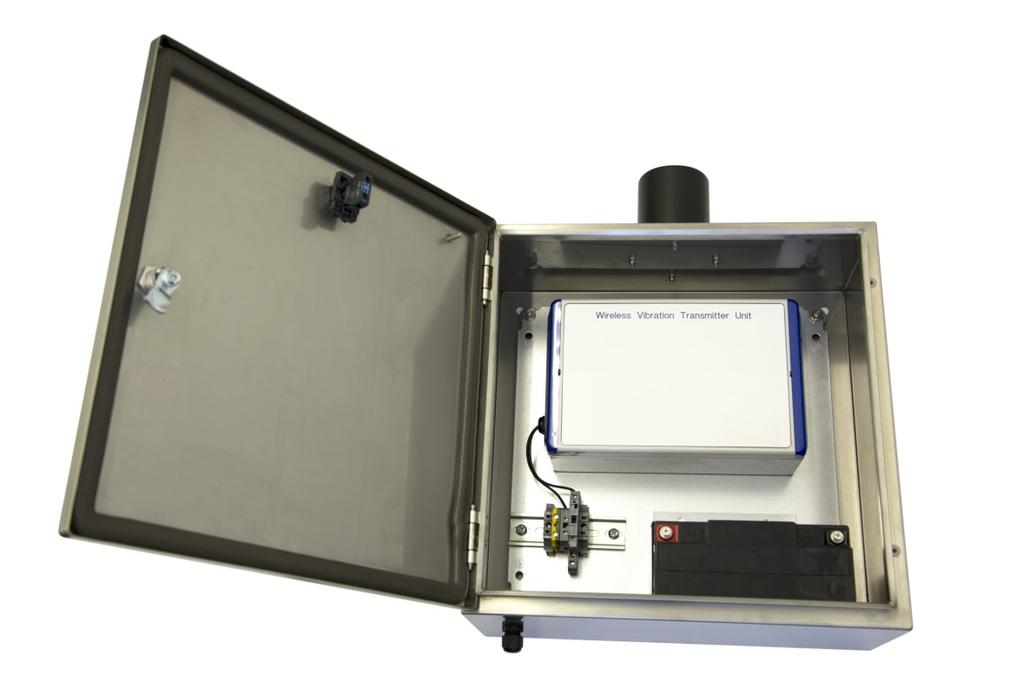
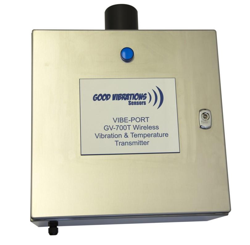
10 INSTALLATION OF GV - 700T TRANSMITTER 10 Terminal Block Wiring HS150T and 150ST The Transmitter Unit (GV-700T) should have up to 8 accelerometers connected into the 8 quad deck terminals with the connections as shown for each accelerometer from top to bottom. The following table provides details of the standard HS-150T and HS-150ST sensor wiring. Input Wire Colour Description 1 White Sensor Signal 2 Black Sensor Ground 3 Red/Brown Sensor Temperature Screen Screen Screen Connect the Power Source (12V Battery or mains power adaptor) to the 2 way connector. Once power is applied the Blue LED on the front of the unit will light when that Transmitter is turned on by a connected Receiver. P10 10 simplifying Wireless
11 INSTALLATION OF GV - 701R RECEIVER 11 The Receiver Unit (GV-701R) Connect the Power Source (12V Battery or mains power adaptor) to the 2 way connector. Connect the Vibration Analyser to the Vibration BNC connector on the front panel. Connect the Temperature monitor to the Temperature BNC connector on the front panel. See below for power connection diagram. Installation recommendations: It is important when the system is installed to ensure that the transmitter and receiver enclosures are mounted in the best possible locations to ensure the optimum performance of the system. The following points should be noted when siting the units: 1. Both boxes must be mounted in the same orientation to ensure that both antennas have the same polarization. 2. Ideally both enclosures will be mounted vertically. 3. Ideally the units will be mounted with clear line of sight between them, it is important to reduce obstacles to a minimum, especially metallic obstacles. 4. The units should be mounted at as near the same height as possible. 5. The enclosures should be mounted away from any metal infrastructure where possible. P11 11 simplifying Wireless
12 12 USING MULTIPLE TRANSMITTERS BACK TO ONE RECEIVER Up to eight transmitters may be connected to a single receiver, the receiver part code changes to state how many transmitters are connected, e.g. GV-701R, GV-702R, GV-703R up to GV-708R. This enables a receiver to link to up to 64 vibration sensors as each transmitter has eight input channels. Usually the system is factory configured such that each transmitter is labelled with a Transmitter Number which is simply selected using an eight way switch on the receiver front panel. All receiver units are programmed to accept up to eight transmitters but the selector switch is only included in the build if multiple transmitters have been ordered. If a system has been ordered with 4 transmitter units and then four more transmitter units are added afterwards, the new transmitters can be supplied already configured as Transmitter Numbers five to eight and will link to the receiver when the appropriate channel number is selected. In detail each Receiver unit is programmed with a unique fixed IP address and the eight transmitters will be allocated the next 8 IP addresses following on from that. So that if a receiver had an IP address of Transmitter number one would have an IP address of , transmitter number two would be and so on. This means that it is easy to add new transmitters to an existing system if required. P12 12 simplifying Wireless
13 13 OPERATING THE WIRELESS SYSTEM GV - 700T and GV - 701R GV - 700T and GV - 701R INTERNAL LED FUNCTIONALITY 1. Push the Power ON/OFF switch in on the front panel of HS-701R so that the switch stays in. The ON/OFF LED will light to show the power is ON. 2. The Blue Collect Data LED in both of the front panel switches will light for 2 seconds to indicate that the system is starting. 3. The Collect Data LED will then flash while the link to the transmitter is made, this will take up to 90 seconds to complete at this point select which channel is to be monitored on the Channel Select switch. 4. Select the required Channel number using the Channel select switch. The Collect Data LED will flash for around 6 seconds while the link to the required channel is made and then be solid ON to indicate the link is made and data is being received. The vibration data signal will now be available on the Vibration BNC connector and the temperature reading is on the Temperature BNC connector. To change channel simply select the new channel and wait for the Collect Data LED to be solid ON. 5. To stop the data transfer, press the ON/OFF switch and all LED s will switch off. 6. If the data link fails, the Collect Data LED will flash and the system will attempt to reconnect. If the link is re-established the Collect Data switch will flash twice and stay on, if the link fails to re-establish the LED will continue to flash. 7. The DC Bias level is present, so the data collector will need to be set up for Non Powered, using HS-AC126 dual output cable for vibration and temperature. There are two red LED s on the daughterboard within both the transmitter and receiver units. The operation is as follows: RECEIVER UNIT Top position Red LED This LED will be solid ON when the receiver has successfully booted up and is ready to connect to a transmitter Bottom position Red LED This will flash when the unit is first switched on and will then go off when the system has booted up. TRANSMITTER UNIT Top position Red LED Will flash when the transmitter is powered on and will be solid ON when the transmitter has linked to the receiver unit Bottom position Red LED This will flash when the unit is first switched on and will then go off when the system has booted up. simplifying Wireless P13 13


14 14 GV - 721R-PC PORTABLE RECEIVER 1. When using multiple transmitters the GV-721R-PC portable receiver is ideal. 2. In a light weight industrial pelican enclosure the GV-721R-PC can connect up to 8 x GV-700T transmitters. 3. Another advantage of the GV-721R-PC is when a transmitter is on a moving asset and where there are challenges getting good line of site connection. With the portable receiver the technician can choose the ideal location to collect the data. PORTABLE RECEIVER WITH ANTENNA PORTABLE RECEIVER simplifying Wireless - no software P14 14
15 15 GV - 700T and GV - 701R WIRELESS SYSTEM TROUBLESHOOTING GUIDE Please ensure all wiring is correct as per installation instructions before use. Unable to create a wireless link 1. Check Power Supply or Battery is providing correct operational voltage, and if battery powered, ensure that the battery is sufficiently charged. 2. Is the Receiver Power ON/OFF switch in the depressed ON position? 3. Has 90 seconds elapsed since switching the system ON to allow the radio link to be established? No Wait for 90 seconds after switch on. 4. When the Power ON/OFF switch was pushed, did both the Power ON/OFF and Collect Data switches light up blue for 2 seconds to indicate that the system is beginning its start up procedures? No Check power supply is correct or battery is sufficiently charged. 5. Check power supply/battery is connected correctly. 6. Has the correct Channel number been selected on the Channel Select switch? 7. Has the Collect Data switch light stopped flashing? No - Press Collect Data switch and check that the Power ON/OFF switch lights up blue for 2 seconds, at which point the Collect Data switch will then light up blue if a data connection has been established. 8. Has the Collect Data switch light turned on? Yes The unit is now receiving data. No - No data link was established. Try changing the channel number. If no link is made again, check that the area between the receiver and the transmitter is still a clear line of sight, and that nothing is now blocking this area. 9. If there is still no link, try a system restart. Switch the Power ON/OFF switch off and wait for 90 seconds to allow time for all remote transmitters to switch themselves into low power mode. 10. After the 90 seconds, switch the receiver on again and wait for 90 seconds to allow the radio link to be established. 11. If the link is still failing, the problem may be due to the power supply or battery in the remote transmitter. Check the blue LED on the front cover is lit. If not check that the transmitter supply voltage is as required. 12. Check that the transmitter supply voltage is as required. Conserving Battery Power 1. The system uses a lot of power while transmitting the vibration data across the link, and it is very important that after the data has been analysed the Power ON/OFF switch should be put into the OFF position. This will reduce the receiver power drain to a minimum, and in addition within 90 seconds all the transmitters will switch into a very low power drain mode to ensure that the battery will remain charged for as long as possible. 2. If GV-700T and GV-701R are using battery power battery life is designed to last for 12 months when data is taken once per month. It is advised to have a spare battery and charger kit on standby for a 12 monthly change out. simplifying Wireless - no software P15 15
16 16 VIBE-PORT WIRELESS VIBRATION SYSTEM - OPERATIONAL OVERVIEW GV - 700T TRANSMITTER UNIT The process of collecting data begins with the operator selecting a channel number after a link has been established and then pressing the Collect Data switch. The Receiver unit wakes up the transmitter by sending a wireless message with the address of the transmitter involved. This message also contains the channel number of the vibration sensor to be monitored. The transmitter unit selects that channel by using a multiplexor on the input stage as shown above. The signal from the vibration sensor then passes through a multi-stage amplification and filtering stage to a high speed data acquisition module. This module reads the value of the waveform every 30uS and sends the data to the wireless module. The wireless module encodes this data in a unique way before sending it across the wireless link to the receiver. The transmitter also takes a single temperature reading if a dual output sensor is being used and transmits that value across the wireless link. The transmitter unit continues sending data until it receives either a different channel number request from the receiver, or is remotely turned off by the receiver. P16 16 simplifying Wireless - no software
17 17 VIBE-PORT WIRELESS VIBRATION SYSTEM - OPERATIONAL OVERVIEW GV - 701R RECEIVER UNIT The receiver unit is powered up using the ON/ OFF switch on the front panel. The operator can then select the channel number of the vibration sensor required and presses the Collect Data switch. The receiver sends a wake-up message to the transmitter unit which powers up the transmitter and tells the transmitter which channel number data is required from. This connection may take up to 90 seconds to make as the transmitter unit needs to boot up and form the wireless link. When the connection is made and data is being received the Collect Data LED is lit continuously. The operator can then collect the data from that channel number for as long as is required, before either selecting another channel or turning the system off. The data is received by the wireless module and is read by the system controller microprocessor. This interprets the data level and sends the level out to the high speed DAC converter. This outputs the appropriate voltage level which is then fed through a multi-stage filter and gain circuit before being available on the BNC connector as a nearly perfect copy of the original input signal. The temperature reading is decoded and the corresponding voltage level outputted to the Temperature BNC connector. When the operator has collected all the data required the system must be switched off using the ON/OFF switch on the Receiver unit. Sampling rate is 33kHz, which translates to a reading every 30 micro seconds. simplifying Wireless - no software P17 17
18 18 FREQUENCY RESPONSE FREQUENCY RESPONSE OF THE GV PORT IS 2 Hz - 15 khz Warranty All goods are guaranteed against defects in materials and workmanship subject to specific exclusions, for a period of 36 months from date of delivery to the end user. The warranty is void if unauthorised persons or agents attempt repair or, if the product has been used for purpose for which it was not intended and/or subject to abuse or wilful neglect. No liability can be accepted for loss of items and/or component parts. It is expected that the user will take sufficient precautions to safeguard all guaranteed items. simplifying Wireless - no soft- P18 18


19 DATA COLLECTOR SETUP 19 Typically vibration sensors for routine condition monitoring are powered by a portable vibration analyser. The Industrial Interface Wireless unit sensors are powered separately. In this note we describe the cables required and how to setup the software to ensure no power is provided to the wireless unit. Other analysers can be used to collect data from the wireless unit just ensure in the software setup the power is turned to off and a volts input to the analyser is used. CSI 2130 Vibration Analyser Accel / Volts Adapter 625 or Dual Volts Adapter A06290V BNC to BNC cable Sensor power box unchecked. CSI 2140 Vibration Analyser Volts Cable D25479 into Volts/Tach connector Option - Volts input and standard BNC cable Sensor power box unchecked. Wireless Vibration Tests A variable speed motor with an unbalanced mass was used to generate the vibration to be measured. HS100 series accelerometer glue mounted to the motor base and connected to the wireless system. Database created in Emerson's MHM software to collect the data during the tests. Vibration velocity mm/sec RMS was selected as the primary measurement unit for the readings. CSI 2130 & CSI 2140 Analysers used to collect the data with a Volts input and power off in the software. Wireless vibration readings were collected and direct readings from the accelerometer were also collected as a comparison for all of the tests. Tests 1 & 2 showed comparable levels with the trial wireless unit at 100Hz and 1000 Hz range P19 19 simplifying Wireless - no software
20 VIBE - PORT TRANSMITTER ASSEMBLY ENCLOSURE DIMENSIONS 20 P20 20
21 VIBE - PORT RECEIVER ASSEMBLY ENCLOSURE DIMENSIONS 21 P21 21

22 22 HS - 150ST SERIES VIBRATION AND TEMPERATURE SENSOR P22 22

23 23 HS - 150ST SERIES VIBRATION AND TEMPERATURE SENSOR P23 23

24 24 HS - AC186 CABLE ASSEMBLY P24 24
25 25 VIBE - PORT SEALED LEAD - ACID BATTERY P25 25

26 VIBE - PORT LITHIUM ION POLYMER BATTERY 26 CAPACITY, WEIGHT and SIZE OPERATING PARAMETERS Maximum Continuous Discharge Current 10A Maximum Peak Current 40A for 10mS Nominal Voltage 12V Discharge Cut-off Voltage 9V Charging Voltage 12.6V Temperature Range (Charging) 0 C 45 C Temperature Range (Discharging) -20 C - 60 C DURABILITY Cycle Life >300 Cycles This is based on charging at a standard rate with a discharge from full capacity to 9V at 5A. Rest time of 30 minutes between charge and discharge. Cycle life is classed as when discharge capacity is at 70% of original. Note that the battery still has a useful life after this. Self - Discharge <0.5% per day PROTECTION The battery pack is protected against over charge and discharge, there is also short circuit protection. GUARANTEE The battery pack and charger are guaranteed against manufacturing defect for 12 months from the date of purchase P27 26
 2 4925 2702 Fax: + 61 (0) 2 4925 2703 www.gvsensors.com.")
27 27 Licenced Distributor simplifying Wireless, no software GVS - Reliability Products GVS - Reliability Products Pty Ltd Suite 3G, Level 3, Hunter Street, Newcastle, NSW Tel: + 61 (0) Fax: + 61 (0)
700 MHz MiMO Yagi Antenna
 Seriously Smart Radios for Linking Critical Communications Infrastructure 700 MHz MiMO Yagi Antenna The 700 MHz MiMO Yagi Antenna with Dual Polarization is a high gain, premium quality antenna with excellent
ID SERIES OUTDOOR INDUSTRIAL DIPOLE ANTENNA
 ID SERIES OUTDOOR INDUSTRIAL DIPOLE ANTENNA Phone: (8) 736-6677 / Int: +1 541-471-6256 Email: info@linxtechnologies.com / Address: 159 Ort Lane, Merlin, OR 97532 ID SERIES OUTDOOR INDUSTRIAL DIPOLE ANTENNA
BENEFITS 3G/4G LTE & Wi-Fi communications in a single solution Applicable for both metal and non-metallic* surface
 LOW PROFILE SURFACE MOUNT 698-960/1710-2700 MHZ DISK-PUCK ANTENNA The Laird Patent Pending LPS69273NT antenna is a multiband low profile omnidirectional diskpuck antenna operating over the 698-960 MHz
SC200 Series. Signal Conditioner MNX10020, REV H 10/17/ Connection Technology Center, Inc Rae Boulevard Victor, NY (585)
") SC200 Series Signal Conditioner MNX10020, REV H 10/17/2012 1 CONTENTS SECTION 1: OVERVIEW... 4 Introduction... 4 Description... 4 Ordering Information... 4 Specifications... 5 Environmental... 5 Electrical...
SC200 Series Signal Conditioner MNX10020, REV H 10/17/2012 1 CONTENTS SECTION 1: OVERVIEW... 4 Introduction... 4 Description... 4 Ordering Information... 4 Specifications... 5 Environmental... 5 Electrical...
SPECIFICATION. MIMO Single Band 2.4GHz. ISM Bands/ZigBee/WLAN/Bluetooth. High Isolation between Antenna Elements. UV and vandal resistant PE housing
 SPECIFICATION Part No. : MA515.C.CG.001 Product Name : Heavy Duty Screw Mount Antenna MIMO Single Band 2.4GHz Features : 2.4GHz suitable for ISM Bands/ZigBee/WLAN/Bluetooth IEEE.802.11n High Isolation
Operations Manual Edition 3.1
 Operations Manual Edition 3.1 MREL GROUP OF COMPANIES LIMITED 1555 Sydenham Road, Kingston, Ontario K7L 4V4 Canada T: +1-613-545-0466 F: +1-613-542-8029 E: blasting@mrel.com www.mrel.com ii Copyright Information
PAMS. User s Manual. Portable Attenuation Measurement System. The solution for making easy shielding effectiveness measurements.
 PAMS Portable Attenuation Measurement System User s Manual The solution for making easy shielding effectiveness measurements. 310-010042-001 TABLE OF CONTENTS Warranty Statement 1 Chapter 1 General Information
SPECIFICATION. Product Name : Heavy Duty Screw Mount Antenna MIMO Dual Band 2.4/5.0GHz
 SPECIFICATION Part No. : MA510.C.CG.005 Product Name : Heavy Duty Screw Mount Antenna MIMO Dual Band 2.4/5.0GHz Features : 2.4GHz/5.0GHz suitable for ISM Bands/ZigBee/WLAN/Bluetooth IEEE.802.11n/IEEE.802.11ac
Installation & Operation Manual SAGA1-K Series Industrial Radio Remote Control
 Installation & Operation Manual SAGA1-K Series Industrial Radio Remote Control Gain Electronic Co. Ltd. Table Of Contents Safety Considerations ------------------------------------------------------------2
The Reverse Polarity TNC(m) RF connector can be easily secured or removed from equipment in the field by a single gloved hand, no tools required.
 RF connector can be easily secured or removed from equipment in the field by a single gloved hand, no tools required.") Overview Southwest Antennas is a half wave dipole omni antenna with a frequency range of 1.35 to 1.40 GHz and 2.15 dbi of peak gain. This product features an integrated RF bandpass filter to help eliminate
Overview Southwest Antennas is a half wave dipole omni antenna with a frequency range of 1.35 to 1.40 GHz and 2.15 dbi of peak gain. This product features an integrated RF bandpass filter to help eliminate
HyperLink Wireless 2.4/ 5 GHz Dual Band / Dual Polarized Omni Antenna Model: HG DPU
 HyperLink Wireless 2.4/ 5 GHz Dual Band / Dual Polarized Omni Antenna Model: HG2458-11DPU Applications 2.4/5 GHz IEEE 802.11a/b/g applications Supports 1x2, 2x2 and 4x4 MIMO AP/Routers WiMax, WISP and
HyperLink Wireless High Density 2.4/5 GHz Four Element Dual Polarized Flat Panel Antenna Model: HG HDP-4NF
 HyperLink Wireless High Density 2.4/5 GHz Four Element Dual Polarized Flat Panel Antenna Model: HG2458-13HDP-4NF Features Four independent antennas, two vertical and two horizontal Narrow beamwidth for
MTN/8066/G-MAC VIBRATION MODULE
 Monitran Ltd. Monitor House, Hazlemere Road Penn, Bucks. HP10 8AD England Tel: +44 (0) 1494 816569 Fax: +44 (0) 1494 812256 E-Mail: info@monitran.co.uk Web Site: www.monitran.co.uk MTN/8066/G-MAC VIBRATION
CerePlex W. Instructions for Use. 630 Komas Drive Suite 200 Salt Lake City UT USA P F
 630 Komas Drive Suite 200 Salt Lake City UT 84108 USA P +1 801.582.5533 F +1 801.582.1509 www.blackrockmicro.com CerePlex W Instructions for Use Table of Contents Table of Contents... 2 Warnings and Contraindications...
SPECIFICATION. MIMO Dual Band 2.4/5.0GHz. ISM Bands/ZigBee/WLAN/Bluetooth. IEEE n/IEEE ac. High Isolation between Antenna Elements
 SPECIFICATION Part No. : MA510.C.CG.005 Product Name : Heavy Duty Screw Mount Antenna MIMO Dual Band 2.4/5.0GHz Features : 2.4GHz/5.0GHz suitable for ISM Bands/ZigBee/WLAN/Bluetooth IEEE.802.11n/IEEE.802.11ac
CEC VIBRATION TRANSMITTER
 CEC 1-808 VIBRATION TRANSMITTER Operation & Maintenance Manual 746 Arrow Grand Circle Covina, CA 91722 United States of America Tel: (626) 938-0200 Fax: (626) 938-0202 Internet: http://www.cecvp.com E-mail:
OMNI-DIRECTIONAL WIDEBAND ANTENNA MODEL EM GHz - 18 GHz
 INSTRUCTION MANUAL OMNI-DIRECTIONAL WIDEBAND ANTENNA MODEL EM-6865 2 GHz - 18 GHz INSTRUCTION MANUAL THIS INSTRUCTION MANUAL AND ITS ASSOCIATED INFORMATION IS PRO- PRIETARY. UNAUTHORIZED REPRO- DUCTION
Model 7000 Low Noise Differential Preamplifier
 Model 7000 Low Noise Differential Preamplifier Operating Manual Service and Warranty Krohn-Hite Instruments are designed and manufactured in accordance with sound engineering practices and should give
Advanced Test Equipment Rentals ATEC (2832)
") Established 1981 Advanced Test Equipment Rentals www.atecorp.com 800-404-ATEC (2832) LOG PERIODIC DIPOLES 20 MHz - 18 GHz TRANSMIT - RECEIVE SPECIFICATIONS ELECTRICAL Impedance: 50 ohms INDIVIDUALLY CALIBRATED
Established 1981 Advanced Test Equipment Rentals www.atecorp.com 800-404-ATEC (2832) LOG PERIODIC DIPOLES 20 MHz - 18 GHz TRANSMIT - RECEIVE SPECIFICATIONS ELECTRICAL Impedance: 50 ohms INDIVIDUALLY CALIBRATED
Radio Remote(s) (Installation Manual)
 (Installation Manual)") Radio Remote(s) (Installation Manual) 87 Progress Avenue, Tyngsboro, MA 01879, USA Phone (978) 649-4ECU Fax (978) 649-8363 http://www.qtiusa.com Trademarks, Version, Printing, and Copyright Trademarks
Radio Remote(s) (Installation Manual) 87 Progress Avenue, Tyngsboro, MA 01879, USA Phone (978) 649-4ECU Fax (978) 649-8363 http://www.qtiusa.com Trademarks, Version, Printing, and Copyright Trademarks
Synthesized Base Station Transmitter
 BST-75 OPERATOR S MANUAL (72-76 MHz) Synthesized Base Station Transmitter 357 West 2700 South Salt Lake City, Utah 84115 Phone: (800) 496-3463 Fax: (801) 484-6906 www.comtek.com TABLE OF CONTENTS Introduction...
COMBILOG ANTENNA MODEL AC MHz. rev: 0202
 COMBILOG ANTENNA 30-2000 MHz MODEL AC-220 rev: 0202 WARRANTY All equipment manufactured by Com-Power Corporation is warranted against defects in material and workmanship for a period of two (2) years from
Appearance of device and accessories may vary.
 Mobile 4G Smart Technology Signal Booster Contents: How it Works.... 1 Before Getting Started.... 2 Quick Installation Overview.... 2 Installing the Outside Antenna.... 2 Installing the Low-Profile Antenna....
1510A PRECISION SIGNAL SIMULATOR
 A worldwide leader in precision measurement solutions Portable signal source for calibrating electronic equipment and machinery monitoring systems. 1510A PRECISION SIGNAL SIMULATOR Voltage Signals Charge
WEL-200 O P E R A T I N G I N S T R U C T I O N S W I R E L E S S E D G E L I N K
 O P E R A T I N G I N S T R U C T I O N S WEL-200 TM W I R E L E S S E D G E L I N K 4564 Johnston Parkway, Cleveland, Ohio 44128 P. 800 426 9912 F. 216 518 9884 Sales Inquiries: salessupport@emxinc.com
6.2 dbi , MHz IP C to +70 C
 Making wireless happen ANTENNAS OMNI-6 SERIES HIGH PERFORMANCE 2X2 MIMO LINEAR MHZ 3MHZ ANTENNA 6.2 dbi -, - -217-34-3 MHz Omni-Directional Increase x Mb/s 2.4 GHz IP 65 UL 94 HB 2x2 MIMO 2x2 MIMO High
Heavy Duty Screw Mount Antenna - Dual-Band GHz
 Hercules WS.01.B.305151 Description: Heavy Duty Screw Mount Antenna - Dual-Band 2.4 5.2GHz Features: 2.4GHz 5.2GHz suitable for ISM Bands/ZigBee/WLAN/Bluetooth IEEE.802.11/IEEE.802.15 UV and Vandal Resistant
Link Mobile Gateway User Guide A ProVIEW System Component
 A ProVIEW System Component Omni-ID office locations: US UK China India Southeast Asia Germany 1. CONTENTS 1. Introduction... 3 About this Document... 3 Related Products... 3 Regulatory Approvals... 4 Certifications...
ZT-30 ZeroTEM TRANSMITTER MANUAL
 ZT-30 ZeroTEM TRANSMITTER MANUAL 06 September, 2000 Zonge Engineering and Research Organization, Inc. 3322 East Fort Lowell Road, Tucson, AZ 85716 USA Tel:(520)327-5501 Fax:(520)325-1588 Email:zonge@zonge.com
P700WLS IoProx Receiver
 Installation Manual Warning! This manual contains information on limitations regarding product use and function and information on the limitations as to liability of the manufacturer. The entire manual
Quick Start Guide. ELPRO 105U-L-T Wireless I/O Transmitter Unit. man_105u-l-t_quickstart_v1-8.doc
 Quick Start Guide ELPRO 105U-L-T Wireless I/O Transmitter Unit man_105u-l-t_quickstart_v1-8.doc ELPRO 105U-L-T Wireless I/O Transmitter Unit Quick Start Guide About this document This document is the ELPRO
Quick Start Guide. ELPRO 905U-L-T Wireless I/O Transmitter Unit. man_905u-l-t_quickstart_v1-7.doc
 Quick Start Guide ELPRO 905U-L-T Wireless I/O Transmitter Unit man_905u-l-t_quickstart_v1-7.doc ELPRO 905U-L-T Wireless I/O Transmitter Unit Quick Start Guide About this document This document is the ELPRO
GLR43308 and GLR2708. Setup and programming instructions. for the 8 channel Gigalink receiver. Programming Videos
 GLR43308 and GLR2708 Setup and programming instructions for the 8 channel Gigalink receiver Programming Videos www.elsema.com NOTES IMPORTANT WARNING AND SAFETY INSTRUCTIONS All installations and testing
Product Catalogue. WiMAX & Wireless Antennas. permission of All Max Electronics Ltd. Specifications subject to change without prior notice.
 Ver. 2.4 Ver. 2.4 REVISED MARCH 2014 All Max Electronics Ltd. Product Catalogue WiMAX & Wireless Antennas Revision: 2.4 This document is the exclusive property of All Max Electronics Ltd. and should not
Antenna Overview. Version /11/19
 Antenna Overview Version 3.8 2018/11/19 Contents ANT-RSMA-Omni Set Order No.: 5510000397... 3 Antenna-Kit II WOx003n Order No.: 5520000145... 4 ANT-Omni-vehicle-1.2m Order No.: 600519... 4 ANT-Omni-5-2G-1.2m
Remote Radio Control. WAVE Push button radio control systems
 Remote Radio Control WAVE Push button radio control systems Application Radio Remote Controls have become a key element within a wide range of modern working environments where safety, productivity and
Quick Start Guide. ELPRO 905U-L-T Wireless I/O Transmitter Unit. man_905u-l-t_quickstart_v1.9.doc
 Quick Start Guide ELPRO 905U-L-T Wireless I/O Transmitter Unit man_905u-l-t_quickstart_v1.9.doc About this document This document is the and contains the following sections: Section Basic steps for using
IWR-1 Wireless Pressure & Temperature Receivers - Operating Manual IWR-1. Single Channel Industrial Wireless Pressure/Temperature Receiver
 IWR-1 Wireless Pressure & Temperature Receivers - Operating Manual IWR-1 Single Channel Industrial Wireless Pressure/Temperature Receiver Whilst every effort has been taken to ensure the accuracy of this
Guide. Installation. Wilson Electronics, Inc. In-Building Wireless Amplifi er. Contents:
 Amplifier Installation Guide In-Building Wireless Amplifi er Contents: Guarantee and Warranty 1 Antenna Options and Accessories 2 Before Getting Started / How It Works 2 Installation Overview 3 Installation
Wireless Pulse Transmitter and Receiver System. Ideal for slumpstand wireless metering application
 WPTR FEATURES 1-channel wireless pulse transmission. Wireless Pulse Transmitter and Receiver System Ideal for slumpstand wireless metering application Ideal for slumpstands where wiring back to batch room
Antenna Basics. Antennas. A guide to effective antenna use
 A guide to effective antenna use Antennas Antennas transmit radio signals by converting radio frequency electrical currents into electromagnetic waves. Antennas receive the signals by converting the electromagnetic
Advanced Test Equipment Rentals ATEC (2832)
") Established 1981 Advanced Test Equipment Rentals www.atecorp.com 800-404-ATEC (2832) 6500 Series Loop Antennas User Manual ETS-Lindgren Inc. reserves the right to make changes to any product described
Established 1981 Advanced Test Equipment Rentals www.atecorp.com 800-404-ATEC (2832) 6500 Series Loop Antennas User Manual ETS-Lindgren Inc. reserves the right to make changes to any product described
CS-200. PORTABLE TRAFFIC LIGHT CONTROLLER (Software 1.05) OPERATION AND SERVICE MANUAL
 OPERATION AND SERVICE MANUAL") CS-200 PORTABLE TRAFFIC LIGHT CONTROLLER (Software 1.05) OPERATION AND SERVICE MANUAL CS-200 Operation and Service Manual Page 2 Manufactured by: LINCAST INTERNATIONAL PTY. LTD. 2/3 Sir Laurence Drive
CS-200 PORTABLE TRAFFIC LIGHT CONTROLLER (Software 1.05) OPERATION AND SERVICE MANUAL CS-200 Operation and Service Manual Page 2 Manufactured by: LINCAST INTERNATIONAL PTY. LTD. 2/3 Sir Laurence Drive
WS-29 DUAL CHANNEL WIRELESS BELTPACK
 WS-29 DUAL CHANNEL WIRELESS BELTPACK USER MANUAL Issue March 2011 ASL Intercom BV DESIGNED AND MANUFACTURED BY: ASL INTERCOM BV ZONNEBAAN 42 3542 EG UTRECHT THE NETHERLANDS PHONE: +31 (0)30 2411901 FAX:
IN-BUILDING ANTENNAS
 Ceiling Mount Antenna, 4G LTE MIMO, PIM160 VenU PIM160-ICM Ultra Flat Dual-Polarization LTE MIMO Ceiling Mount Antenna The PIM160-ICM is a dual-polarization LTE MIMO antenna with ultra-low PIM (@ 2x43
SPECIFICATION. Part No. : A.03.B Product Name : 40dB GPS Hercules Heavy Duty Screw Mount Antenna For long cable lengths above 5M
 SPECIFICATION Part No. : A.03.B.1001111 Product Name : 40dB GPS Hercules Heavy Duty Screw Mount Antenna For long cable lengths above 5M Description : Three Stage 40dB Height 29mm Diameter 52mm Applications
VIBCONNECT RF. Wireless Condition Monitoring. Catalog. PRÜFTECHNIK Condition Monitoring Edition: Oder No.: LIT
 VIBCONNECT RF Wireless Condition Monitoring Catalog PRÜFTECHNIK Condition Monitoring info@pruftechnik.com Edition: -04 Oder No.: LIT 7.700.EN Legal notices Both this catalog and the product it describes
AK-18G Antenna Kit Operation Manual
 AK-18G Antenna Kit Operation Manual 1 TABLE OF CONTENTS WARRANTY 3 INTRODUCTION 4 GENERAL INFORMATION 5 OPTIONAL EQUIPMENT 8 FORMULAS 9 MAINTENANCE 10 2 WARRANTY INFORMATION A.H. Systems Inc., warrants
HIGH PERFORMANCE 2X2 MIMO LINEAR MARINE & COASTAL 410MHZ 2700MHZ ANTENNA
 ANTENNAS SERIES OMNI DIRECTIONAL MARINE ANTENNA HIGH PERFORMANCE 2X2 MIMO LINEAR MARINE & COASTAL 410MHZ 2700MHZ ANTENNA 410-470; 690-960; 1710-2170; 2300-2700 MHz 6.2 dbi Increase x Mb/s Omni-Directional
AN Wireless analog data acquisition system with 4-20 ma (current loop) inputs and built-in data logger
 inputs and built-in data logger") Wireless analog data acquisition system with 4-20 ma (current loop) inputs and built-in data logger www.beanair.com Product Video VIDE O OVERVIEW Wireless data logger with 4-20mA current loop inputs (4
Wireless analog data acquisition system with 4-20 ma (current loop) inputs and built-in data logger www.beanair.com Product Video VIDE O OVERVIEW Wireless data logger with 4-20mA current loop inputs (4
200, 201 Series Radio Telemetry Transmitters
 200 DIN Rail Transmitter Encoder Up to 8 Input Channels Volt Free contact Inputs via Screw Terminals 12 / 24Vdc Supply Range; 433MHz Up to 200 Metres 433MHz NB Up to 1,000 Metres 458MHz Up to 6,000 Metres
PRODUCT CATALOG. RF Test. VIAVI Solutions. Antennas
 PRODUCT CATALOG RF Test VIAVI Solutions Antennas Table of Contents Selection Table...2 Omni Antenna G700050353, G700050354, G700050355, G700050356, G700050357...3 Dual Band Omni Antenna G700050359... 5
This Antenna Basics reference guide includes basic information about antenna types, how antennas work, gain, and some installation examples.
 Antenna Basics This Antenna Basics reference guide includes basic information about antenna types, how antennas work, gain, and some installation examples. What Do Antennas Do? Antennas transmit radio
Antenna Overview. Version /10/20
 Antenna Overview Version 2.8 2010/10/20 Contents ANT-Ceiling-Mimo-2G for 802.11n AP Order No.: 5510000209...3 ANT-Omni-4-dual Order No.: 600529...4 ANT-RSMA.KS-D-060-03-1m Order No.: 600402...5 ANT-Omni-vehicle-1.2m
SPECIFICATION. G21 GSM Hercules Gen.II Penta Band Cellular Antenna. Screw-mount (Permanent mount)
") SPECIFICATION G21 GSM Hercules Gen.II Penta Band Cellular Antenna Part No. : G21.B.301111 Product Name : Hercules Gen.II Penta Band Cellular Antenna Screw-mount (Permanent mount) Features : GSM/GPRS/CDMA/EVDO/UMTS/HSPA/WCDMA
SPECIFICATION G21 GSM Hercules Gen.II Penta Band Cellular Antenna Part No. : G21.B.301111 Product Name : Hercules Gen.II Penta Band Cellular Antenna Screw-mount (Permanent mount) Features : GSM/GPRS/CDMA/EVDO/UMTS/HSPA/WCDMA
Guide. Installation. Wilson Electronics, Inc. Direct Connection High Power iden Amplifi er 800 MHz Band. Contents:
 Amplifier Installation Guide Direct Connection High Power iden Amplifi er 800 MHz Band Contents: Guarantee and Warranty 1 Before Getting Started / How it Works 3 Installing a Wilson Outside Antenna - In-Vehicle
The wireless alternative to expensive cabling...
 The wireless alternative to expensive cabling... ELPRO 105U Wireless Solutions for Process Applications New Products... New Solutions The ELPRO 105U range of wireless I/O provides a low cost alternative
RU210. Dual Multi-UHF Wireless System. Item ref: UK, UK User Manual. Version 1.0
 RU210 Dual Multi-UHF Wireless System Item ref: 171.970UK, 171.971UK User Manual Version 1.0 Caution: Please read this manual carefully before operating Damage caused by misuse is not covered by the warranty
Installation and Quick Reference Guide. Disclaimer and warranty 2. Contents of this box 2. Brief background to AIS 3.
 AI3000 AIS Receiver ai3000vf rev 6b Installation and Quick Reference Guide Contents Page Number Disclaimer and warranty 2 Contents of this box 2 Brief background to AIS 3 Introduction 3 Installing the
Modular Radio Telemetry System
 Simple to Use Remote Control 8 Channels per Transmitter 16 Channels per Receiver Upto 48 Transmitters per system Auto Transmit Mode Secure RF Protocol Automatic Watchdog Transmission Range: Upto 200 metres
SPECIFICATION. 3in1 Combination Antenna. GPS/GLONASS/GALILEO 1575~1602MHz. Cellular GSM/CDMA/HSPA/UMTS. Dual band Wi-Fi 2.4GHz / 5.
 SPECIFICATION Part No. : MA600.A.ABC.007 Product Name : MA600 Spartan Screw mount 3in1 Combination Antenna GPS/GLONASS/GALILEO 1575~1602MHz Cellular GSM/CDMA/HSPA/UMTS Dual band Wi-Fi 2.4GHz / 5.8GHz Feature
Synthesized Base Station Transmitter
 BST-25 OPERATOR S MANUAL (216 MHz) Synthesized Base Station Transmitter 357 West 2700 South Salt Lake City, Utah 84115 Phone: (800) 496-3463 Fax: (801) 484-6906 http://www.comtek.com INTRODUCTION BST-25
RADOME OMNI ANTENNA GHz, 6 dbi, FOAM FILLED
 RADOME OMNI 5.15-5.975 GHz, 6 dbi, FOAM FILLED PAGE 1/8 ISSUE 1525 SERIES RADOME OMNI 5.15-5.975 GHz, 6 dbi, FOAM FILLED PAGE 2/8 ISSUE 1525 SERIES ELECTRICAL CHARACTERISTICS Frequency:..... 5150-5975
MIMO IN - 1 MIMO LTE/GPS/WI-FI ANTENNA
 Making wireless happen ANTENNAS MIMO -1 MIMO -1 5 - IN - 1 MIMO LTE/GPS/WI-FI ANTENNA 698-960 MHz & 1710-2700 MHz. 4 x Omni-Directional Increase x Mb/s M2M GPS/ GLONASS -40 C to +70 C IP 65 UL 94 V-1 5
WX100 Series Installation-grade Wireless Microphone System. featuring the WX160 A/V Desk stand transmitter
 WX100 Series Installation-grade Wireless Microphone System featuring the WX160 A/V Desk stand transmitter WX100 Series Installation-grade Wireless Microphone System WX100 Receiver...page 4 WX160 Desk
5 - IN - 1 MIMO LTE/GPS/WI-FI ANTENNA
 Making wireless happen ANTENNAS MIMO -1 MIMO -1 5 - IN - 1 MIMO LTE/GPS/WI-FI ANTENNA 698-960 MHz & 1710-2700 MHz. 4 x Omni-Directional Increase x Mb/s M2M GPS/ GLONASS -40 C to +70 C IP 65 UL 94 V-1 5
Guide. Installation. Wilson Electronics, Inc. In-Building Wireless Amplifi er. Contents:
 Amplifier Installation Guide In-Building Wireless Amplifi er Contents: Guarantee and Warranty 1 Antenna Options and Accessories 2 Before Getting Started / How It Works 3 Installation Overview 4 Installing
HyperLink Wireless Low PIM DAS 2x2 MIMO Ceiling Antenna Model: HG72706DPCUPR-NF
 HyperLink Wireless Low PIM DAS 2x2 MIMO Ceiling Antenna Model: HG72706DPCUPR-NF Applications DAS (Distributed Antenna Systems) 700 MHz and cellular applications AWS (Advanced wireless services) and PCS
TONE ALERT RECEIVER MODEL 2TR9A. P.O. Box West Pacific. Lexington, NE 68850
 TONE ALERT RECEIVER MODEL 2TR9A P.O. Box 480 1311 West Pacific Lexington, NE 68850 Phone: (800)445-0007 (308)324-6661 Fax: (308)324-4985 www.veetronix.com Tomorrow's Technology Today CONTROLS AND FUNCTIONS
Specification. Spartan MA650.A.AB.002
 MA650.A.AB.002 on ground-plane Spartan MA650.A.AB.002 Specification Part No. Product Name Feature MA650.A.AB.002 Spartan 2in1 MA.650 with 10M cable length Low Profile Screw Mount (Permanent Mount) GPS/GLONASS
IWR-1. Single Channel Industrial Wireless Pressure Receiver
 IWR-1 Wireless Pressure Receivers - Operating Manual IWR-1 Single Channel Industrial Wireless Pressure Receiver Whilst every effort has been taken to ensure the accuracy of this document, we accept no
UltraTEV Locator. Portable PD (Partial Discharge) investigation system. benefits. features. FACT: 85% of disruptive substation failures are PD-related
 investigation system. benefits. features. FACT: 85% of disruptive substation failures are PD-related") UltraTEV Locator Portable PD (Partial Discharge) investigation system Locates, measures and records PD activity in all substation assets including cables benefits Locating and measuring PD activity to
UltraTEV Locator Portable PD (Partial Discharge) investigation system Locates, measures and records PD activity in all substation assets including cables benefits Locating and measuring PD activity to
411LA Broadband Power Amplifier
 411LA Broadband Power Amplifier HIGH RF VOLTAGES MAY BE PRESENT AT THE OUTPUT OF THIS UNIT. All operating personnel should use extreme caution in handling these voltages and be thoroughly familiar with
Watcheye S AIS Splitter. manual
 Watcheye S AIS Splitter manual Thank you for buying this AIS antenna splitter. This product has been engineered to offer you the highest level of performance and durability and we hope that it will provide
PRODUCTS SHIPPING QUALITY SERVICE
 FE Technology is an industry leader in the manufacturing, sales and distribution of Antennas; especially in the Portable Antenna product area. Our organization has over 20 years experience in serving the
SCADA and Telemetry Solutions. SCADALink IO900. Modular Wireless I/O System. User Manual Version V1.3 for SCADALink IO900 BENTEK SYSTEMS LTD
 Modular Wireless I/O System User Manual Version V. for BENTEK SYSTEMS LTD #, 0 Ave S.E. Calgary, AB, Canada TB 0L Ph:(0) Fax:(0) email: sales@scadalink.com web: The is a Modular Wireless I/O System that
Single Channel Radio Mic System USER MANUAL. WMU-116-H (Hand Held) WMU-116-B (Belt Pack) Single Channel Radio Mic System
 WMU-116-B (Belt Pack) Single Channel Radio Mic System") Single Channel Radio Mic System USER MANUAL WMU-116-H (Hand Held) WMU-116-B (Belt Pack) Single Channel Radio Mic System Welcome Thank you for choosing Hill Audio for your sound system. To make sure that
Single Channel Radio Mic System USER MANUAL WMU-116-H (Hand Held) WMU-116-B (Belt Pack) Single Channel Radio Mic System Welcome Thank you for choosing Hill Audio for your sound system. To make sure that
P700-WLS ioprox Receiver
 Installation Manual DN1628-1611 Pre-Installation Notes Copyright 2016 Tyco International Ltd. and its Respective Companies. All Rights Reserved. All specifications were current as of publication date and
Scalable Ionospheric Analyser SIA 24/6
 Scalable Ionospheric Analyser SIA 24/6 Technical Overview Functional description The ATRAD Scalable Ionospheric Analyser SIA24/6 is designed to observe ionospheric irregularities and their drift in the
Telemetrie-Messtechnik Schnorrenberg
 Telemetrie-Messtechnik Schnorrenberg CTP8-Rotate 8 (4) channel telemetry for rotating applications like wheels or rotors, high signal bandwidth, 16bit, software programmable Inputs for STG, TH-K, ICP or
PRO Professional Radio Control Series Applications
 204 205 Ready to Use Remote Control 4, 8/16 Channel Systems Range: Up to 200 metres at 433MHz Up to 1,000 metres at 433MHz NB Relay Outputs: Momentary, Latching, Timed Receiver IP65 Applications Lighting
MIMO MIMO LTE/GPS ANTENNA
 Making wireless happen ANTENNAS MIMO -1-02 MIMO -1-02 MIMO LTE/GPS ANTENNA 698-960 MHz & 1710-2700 MHz. 2 x Omni-Directional Increase x Mb/s M2M GPS/ GLONASS -40 C to +70 C IP 65 UL 94 V-1 MIMO futureproof
Professional UHF Rechargeable Wireless Microphone System POWER ON/OFF BATTERY CHARGE. Green Light (Full) Better Music Builder DOWN VOLUME
 Better Music Builder DOWN VOLUME") Green Light (Full) KARAOKE Professional UHF Rechargeable Wireless Microphone System VM-93C Operating Instructions UHF Frequency 64 Selectable POWER ON/OFF CHARGE Better Music Builder VM-93C CHARGER UHF
Green Light (Full) KARAOKE Professional UHF Rechargeable Wireless Microphone System VM-93C Operating Instructions UHF Frequency 64 Selectable POWER ON/OFF CHARGE Better Music Builder VM-93C CHARGER UHF
HZJF-9007 Fully Functional Partial Discharge Inspector USER MANUAL. Huazheng Electric Manufacturing(Baoding) Co.,Ltd
 Co.,Ltd") HZJF-9007 Fully Functional Partial Discharge Inspector USER MANUAL Huazheng Electric Manufacturing(Baoding) Co.,Ltd Safety Terms and Symbols This manual may contain the terms: Warning! Indicate the conditions
HZJF-9007 Fully Functional Partial Discharge Inspector USER MANUAL Huazheng Electric Manufacturing(Baoding) Co.,Ltd Safety Terms and Symbols This manual may contain the terms: Warning! Indicate the conditions
HL 670 Data / Impulse Transmitter set User Manual. Version 07/2010
 HL 670 Data / Impulse Transmitter set User Manual Version 07/2010 1. Global The Set HL670 is ideal for transferring Timing Data and Impulses. Its 500mW emitting power and its licence free frequency range
User Manual. ProRF Encoder Transmitter & Receiver
 User Manual ProRF Encoder Transmitter & Receiver WARRANTY Accurate Technology, Inc. warrants the ProScale Systems against defective parts and workmanship for 1 year commencing from the date of original
2001A. 200KHz Function Generator Instruction Manual. 99 Washington Street Melrose, MA Phone Toll Free
 2001A 200KHz Function Generator Instruction Manual 99 Washington Street Melrose, MA 02176 Phone 781-665-1400 Toll Free 1-800-517-8431 Visit us at www.testequipmentdepot.com WARRANTY Global Specialties
Mirage B-320-G FEATURES
 Mirage B-320-G The Mirage B-320-G is a VHF power amplifier designed for 2 meters covering 144-148 MHz. The Hi and Lo input selector switch makes this amp useable for both handheld and mobile transceivers.
PI-10 Broadband Power Indicator
 PI-10 Broadband Power Indicator HIGH RF VOLTAGES MAY BE PRESENT AT THE PORTS OF THIS UNIT. All operating personnel should use extreme caution in handling these voltages and be thoroughly familiar with
Contents. Page English 1. French. Spanish. Reset of MIN/MAX records 915 MHz Reception Mounting Care and Maintenance Warranty Information
 Contents Language Page English 1 French Spanish WIRELESS 915 MHz TEMPERATURE STATION Instruction Manual TABLE OF CONTENTS Topic Page Inventory of Contents Features Setting Up Battery Installation Function
Specification. Spartan MA605.A.ABC in1 MA.605 Low Profile Screw-Mount (Permanent Mount) GPS/GLONASS/Cellular/2.4GHz ~ 5GHz Combination Antenna
 GPS/GLONASS/Cellular/2.4GHz ~ 5GHz Combination Antenna") MA65.A.ABC.1 on ground-plane Spartan MA65.A.ABC.1 Specification Part No. Product Name Feature MA65.A.ABC.1 Spartan 3in1 MA.65 Low Profile Screw-Mount (Permanent Mount) GPS/GLONASS/Cellular/2.4GHz ~ 5GHz
MA65.A.ABC.1 on ground-plane Spartan MA65.A.ABC.1 Specification Part No. Product Name Feature MA65.A.ABC.1 Spartan 3in1 MA.65 Low Profile Screw-Mount (Permanent Mount) GPS/GLONASS/Cellular/2.4GHz ~ 5GHz
Thank you for buying this AIS antenna splitter.
 Thank you for buying this AIS antenna splitter. This product has been engineered to offer you the highest level of performance and durability and we hope that it will provide many years of reliable service.
HP ProCurve 6.9/7.7dBi Dual Band Directional Antenna (J8999A) Guide
 Guide") HP ProCurve 6.9/7.7dBi Dual Band Directional Antenna (J8999A) Guide SAFETY The HP ProCurve J8999A and all associated equipment should be installed in accordance with applicable local and national electrical
HP ProCurve 6.9/7.7dBi Dual Band Directional Antenna (J8999A) Guide SAFETY The HP ProCurve J8999A and all associated equipment should be installed in accordance with applicable local and national electrical
SAT SCD/ARGOS INSTRUCTION MANUAL
 INSTRUCTION MANUAL REVISION: 1/03 COPYRIGHT (c) 2000-2003 CAMPBELL SCIENTIFIC, INC. This is a blank page. WARRANTY AND ASSISTANCE This equipment is warranted by CAMPBELL SCIENTIFIC (CANADA) CORP. ( CSC
Broadband Power Amplifier
 601L Broadband Power Amplifier HIGH RF VOLTAGES MAY BE PRESENT AT THE OUTPUT OF THIS UNIT. All operating personnel should use extreme caution in handling these voltages and be thoroughly familiar with
Modular Radio Telemetry System
 Simple to Use Remote Control 8 Channels per Transmitter 16 Channels per Receiver Upto 48 Transmitters per system Auto Transmit Mode Secure RF Protocol Automatic Watchdog Transmission Range: Upto 200 metres
TX518/TX523/TX530 L-Band Video Transmitters
 TX518/TX523/TX530 L-Band Video Transmitters User's Guide & Operating Manual REV. A - 15 Aug 2007 http://www.avalonrf.com/ Avalon RF, Inc. 344 Coogan Way El Cajon, CA 92020 Phone: (619) 401-1967 Fax: (619)
T6+ Analog I/O Section. Installation booklet for part numbers: 5/4-80A-115 5/4-90A-115 5/4-80A /4-90A-1224
 T and T+ are trade names of Trol Systems Inc. TSI reserves the right to make changes to the information contained in this manual without notice. publication /4A115MAN- rev:1 2001 TSI All rights reserved
Model OI-6940 Notis Quad 4-Gas Sensor Assembly
 Model OI-6940 Notis Quad 4-Gas Sensor Assembly Operation Manual Revision 2.3w Product Overview The Otis Instruments, Inc. Gen II WireFree OI-6940 Notis Quad is a battery-powered explosion-proof 4-gas sensor
NCS-C150 INSTRUCTION MANUAL Rev A. Collcomm Inc. Shipping Address 2310 Pendley Road Cumming, Georgia 30041
 NCS-C150 INSTRUCTION MANUAL Rev A Collcomm Inc. d.b.a. NCS Shipping Address 2310 Pendley Road Cumming, Georgia 30041 Mailing Address 1595 Peachtree Parkway Suite 204-123 Cumming, Georgia 30041 Toll Free