CAD/CAM Lamp Project using 2D Design and the X-660 Laser Cutter
|
|
|
- Easter Wilson
- 6 years ago
- Views:
Transcription


1 CAD/CAM Lamp Project using 2D Design and the X-660 Laser Cutter Paul Tate 2008 Booklet Version 2
.")


2 Getting Started the preliminaries The Laser cutter which is going to cut out your acrylic bases and polypropylene shades only recognises certain colours, or to be more precise the RGB numbers which make up those colours. The eight custom colours are have been set to match the laser (X-660). The two identical rows in the Custom colours is purely to give a quick visual check that you have the correct setup on 2D Design. The laser is set to interpret the following colours: Red to indicate lines that have to be cut. Blue for lines that are to scored or etched Green for double depth etching (sometimes) GETTING STARTED Black for construction lines/notes and is set to be ignored by the laser cutter Setting your Page to A4 1. Left Click on Setup then: >Drawing >Layout 2. In the dialogue box select ISO A4 and Landscape. The A4 size will make it easier to work on your design and enable you to print out a record of your CAD work and preparation for CAM cutting for evidence in your design folder. Now Save your work >File > Save As, then your Surname in My Documents 2D Design opens by default to A3 size Paul Tate Page 2 07/12/2009
 3 From the left side toolbox select the Draw a horizontal rectangle if you keep the LHM button pressed you can see the range and their explanations.")
3 Drawing a Square Base 1. On the right hand side toolbox check Grid and Grid Lock is selected. 2. Check the Line colour is set to black (any) 3 From the left side toolbox select the Draw a horizontal rectangle if you keep the LHM button pressed you can see the range and their explanations. DRAWING A SQUARE BASE 4. Draw a rectangle 120mm x 120mm - you can count the squares, each is 10mm or read off the sizes from the relative distance in the bottom bar. 5. Click on the Select tool when finished this will avoid draw any other unwanted boxes or lines. 6. Double check the box is the correct size. 7. Now Save your work >File > Save As, then your Surname in My Documents. 8. Select Draw a series of connected lines tool 9. Then in the middle of each side draw a 20mm square. If your box side is 110mm, 130 or 150mm make this a rectangle 20 x 30mm as it is easier to use the grid lock. 10. To terminate the line Right Click. 11. Now Save your work. Paul Tate Page 3 07/12/2009


4 Drawing a Circular Base 1. On the right hand side toolbox check Grid and Grid Lock is selected. 2. Check the Line colour is set to black. 3 Front the left side toolbox select the Draw a circle with a given radius if you keep the LHM button pressed you can see the range and their explanations. 4. For a 140mm diameter circle set the radius to 70.0mm, then click OK. DRAWING A CIRCULAR BASE 5. Click once near the centre of the page. 6. Click on the Select tool when finished this will avoid draw any other unwanted boxes or lines. 7. Now Save your work >File > Save As, then your Surname in My Documents. 8. Select Draw a series of connected lines tool 9. Draw four 20mm boxes equally spaced around your circle, you will have to continue into the circle. 10. Right click to terminate the line. 11. Select the delete part tool to remove unwanted lines 12. Now Save your work. Paul Tate Page 4 07/12/2009


5 Drawing a triangular base 1. On the right hand side toolbox check Grid and Grid Lock is selected. 2. Check the Line colour is set to black. 3 Front the left side toolbox select the Draw a single line if you keep the LHM button pressed you can see the range and their explanations. DRAWING A TRIANGULAR BASE 4. Draw a line 150mm long, count the squares or use the relative distance in the bottom bar. 5. Select the radius tool, then set the radius to 150mm. 6. Click on each end of the line, then take grid lock off by clicking on and draw a further circle from the intersection if you want a triangle with curved sides. 7. Select the delete part tool to remove un wanted lines. If you require a straight sided triangle draw two additional lines and delete the circles or delete the straight line. Now Save your work >File > Save As, then your Surname in My Documents. Paul Tate Page 5 07/12/2009


6 8. To get locate the centre of your 150mm triangle you have to change the grid size. Double click the grid icon, change the X & Y spacing to 5mm, then OK. 9. Using the Single Line tool, in the middle of each line a box 20mm x 20mm outside the curve. 10. To rotate the triangular shape to make drawing the other tabs select the whole drawing using the Select tool and draw a box around the shape so that its node points are displayed. DRAWING A TRIANGULAR BASE 11. Then select Draw >Transform >Rotate, in the box that opens set the angle to 60 degrees. 12. Click with the LHM button once in the middle of the drawing, then select the Single line tool and draw the second tab at the top. 13. Repeat stages 9,10 & 11 to complete the third tab. 14. Select the delete part tool to remove un wanted lines. Now Save your work. Paul Tate Page 6 07/12/2009
 click once for each rivet hole, the click on the Select tool to deselect.")
7 Adding the Holes 1. From the left toolbox select Draw a circle with a given centre and radius. Set the radius to 3.5mm to give clearance for the plastic rivets. 2. Click on Line Colour and then select the RED in Custom colours. 3. With Grid Lock on (if your holes align with the grid) click once for each rivet hole, the click on the Select tool to deselect. Now Save your work. ADDING THE HOLES Stress Relieving for Tab Bending To reduce the likelihood of snapping the tabs when line bending it is a good idea to have a small hole where the tab intersects. 1. Select the Draw a circle with a given centre and radius. Set the radius to 2.0mm (as you did above), then set the Line Colour back to Black. 2. At each intersection of the tab and body click once with Grid Lock on (if your holes align with the grid), if not turn the Grid Lock off and use guestimation. 3. To make it easier use the Zoom In tool to zoom in and place the circles. Now Save your work. Paul Tate Page 7 07/12/2009

8 Adding Fillets to Corners 1. Select Draw a filleted arc between two lines from the LH tool bar. 2. In the dialogue box specify 3.0mm for the fillet., then select the corner intersecting lines on your base. 3. Some curved shapes this will not work on, in which case select Draw an arc of a given radius tangential to two line tool. Again with a 3.0mm radius. ADDING FILLETS TO CORNERS 3. Use the Delete lines tool to remove unwanted lines left afterwards. 4. Use the Zoom in tool to make it easier to remove unwanted line segments. 5. If you make a mistake use the Undo tool Now Save your work. Paul Tate Page 8 07/12/2009


9 The Bayonet Fixing Hole 1. Select the circle tool and set the radius to 14.2mm (the bayonet diameter is 28mm and a clearance hole is needed). 2. Ensure Grid lock is activated. 3. Select Line Colour and change the colour to Red in the Custom Colours. THE BAYONET FIXING HOLE 4. Select the Circle tool again and set the radius to 20mm and draw a second circle on the same centre point. 5. Use the Single Line tool to draw two lines from the outside circle for 50mm. 6. Use the delete tool to remove the unwanted semicircle. 7. Finally use the Select tool to move the cut out so that it is positioned off centre to allow for bending up to its final raised position. Now Save your work. Paul Tate Page 9 07/12/2009


10 Setting the Cutting Outline As mentioned earlier the laser is set to respond to a set of custom colours. Red has been used to indicate a cut line, Blue a scored or an engraved line. At present only the holes were drawn in red to indicate cut lines. To change the outline to Red we are going to use the Contour tool this will ensure the cutter follows a flowing path around the outline shape. 1. Select the Contour tool and in the box that opens change the spacing to 0. SETTING THE CUTTING OUTLINE 2. Select Line Colour and change it to the Red in Custom colour. 3. With the hand pointer that appears, move the finger to just outside your outline shape then click ONCE only! Then click the Select tool to deselect the Contour Tool. If you click more than once you will add a second or more contours which you cannot see but will have the laser cutter recutting the outline and damaging your work. 4. Now Save your work. If you find that you do not get a continuous red outline this indicates that usually you have a hole or break in your black outline. Select Undo Last, then Zoom In to locate and repair the break before repeating the Contour operation again. Paul Tate Page 10 07/12/2009


11 Adding Text to the Base 1. Select the Text Tool 2. The click on the drawing and the Text Entry box appears type into this what you require. 3. Click on Settings, change the Height to 5.00mm, the Line Colour to Blue from the Custom range and the Fill Colour to white. You can change the font but avoid fiddly styles. ADDING TEXT TO THE BASE 4. If you wish to change your text etc., use the Select tool to select it than on the Property box that appears in the bottom right corner click on it to reopen the Text Setting dialogue box. 5. Now Save your work. Paul Tate Page 11 07/12/2009

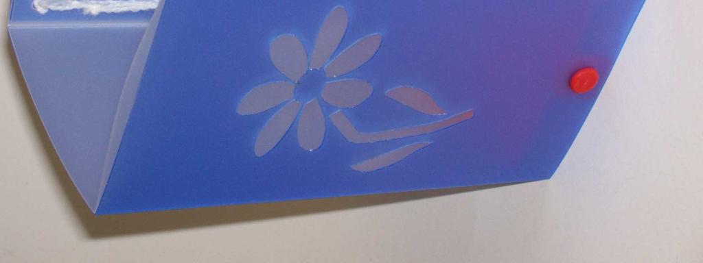
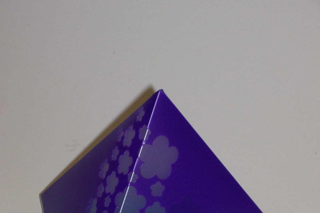
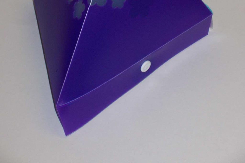
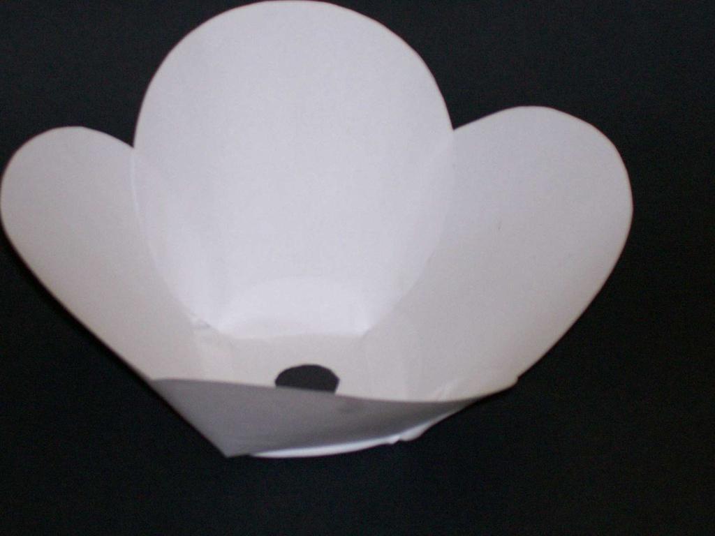
12 Producing the Shade A range of shades have already been produced which you will find from 2D Design clicking on the Look in box and then navigating to: >Hnet-ns-dt\sharedro >Year 8 >Graphics PRODUCING THE SHADE Remember that once you have opened the correct shade for your base to: File >Save As and save in your documents as your Surname_colour You can now add your decoration to your shade do not make it too complicated or fussy. Colours available are: Blue Purple Green Red Paul Tate Page 12 07/12/2009


.")


13 Adding Stencils to Shade 1. Find your stencil or shape from the internet, own drawing, photo etc. 2. Use Paint Shop Pro to trim, as necessary then Copy. PRODUCING THE SHADE 3. Use Paste to place it in your 2D Design and use a corner node to stretch the image to the required size, (hold SHIFT key to maintain aspect ratio). 4. Use the Select tool to highlight your image (if not highlighted). Then select Bitmaps > Contour Bitmap. 5. In the dialogue box that opens set the Contour Spacing to 0.0mm and the Line Colour to RED. 6. With the finger click near to the outline ONCE ONLY! 7. Click on the middle node point and position the outline image on your shade. If want to resize use a corner node and hold the Shift key to maintain the aspect ratio again. Now Save your work. Paul Tate Page 13 07/12/2009


14 PRODUCING THE SHADE Paul Tate Page 14 07/12/2009
Toothbrush Holder. A drawing of the sheet metal part will also be created.
 Prerequisite Knowledge Previous knowledge of the following commands is required to complete this lesson; Sketch (Line, Centerline, Circle, Add Relations, Smart Dimension,), Extrude Boss/Base, and Edit
Hexagons for Art and Illusion Part II Get ready Start a new project FILE New Open Faced Cube Import the hexagon block LIBRARIES
 Hexagons for Art and Illusion Part II In our last lesson, we constructed the perfect hexagon using EasyDraw. We built a six pointed star, a solid faced cube, and put the cube inside the star. This lesson
Creo Revolve Tutorial
 Creo Revolve Tutorial Setup 1. Open Creo Parametric Note: Refer back to the Creo Extrude Tutorial for references and screen shots of the Creo layout 2. Set Working Directory a. From the Model Tree navigate
Engineering Technology
 Engineering Technology Introduction to Parametric Modelling Engineering Technology 1 See Saw Exercise Part 1 Base Commands used New Part This lesson includes Sketching, Extruded Boss/Base, Hole Wizard,
Chapter 2. Drawing Sketches for Solid Models. Learning Objectives
 Chapter 2 Drawing Sketches for Solid Models Learning Objectives After completing this chapter, you will be able to: Start a new template file to draw sketches. Set up the sketching environment. Use various
Sheet Metal OverviewChapter1:
 Sheet Metal OverviewChapter1: Chapter 1 This chapter describes the terminology, design methods, and fundamental tools used in the design of sheet metal parts. Building upon these foundational elements
TOY TRUCK. Figure 1. Orthographic projections of project.
 TOY TRUCK Prepared by: Harry Hawkins The following project is of a small, wooden toy truck. This exercise will provide you with the procedure for constructing the various parts of the design then assembling
Drawing with precision
 Drawing with precision Welcome to Corel DESIGNER, a comprehensive vector-based drawing application for creating technical graphics. Precision is essential in creating technical graphics. This tutorial
Solid Part Four A Bracket Made by Mirroring
 C h a p t e r 5 Solid Part Four A Bracket Made by Mirroring This chapter will cover the following to World Class standards: Sketch of a Solid Problem Draw a Series of Lines Finish the 2D Sketch Extrude
Using Siemens NX 11 Software. The connecting rod
 Using Siemens NX 11 Software The connecting rod Based on a Catia tutorial written by Loïc Stefanski. At the end of this manual, you should obtain the following part: 1 Introduction. Start NX 11 and open
1: INTRODUCTION TO AUTOCAD
 AutoCAD syllabus 1: INTRODUCTION TO AUTOCAD Starting AutoCAD AutoCAD Screen Components Drawing Area Command Window Navigation bar Status bar Invoking Commands in AutoCAD Keyboard Ribbon Application Menu
Basic 2D drawing skills in AutoCAD 2017
 Basic 2D drawing skills in AutoCAD 2017 This Tutorial is going to teach you the basic functions of AutoCAD and make you more efficient with the program. Follow all the steps so you can learn all the skills.
Appendix B: Autocad Booklet YR 9 REFERENCE BOOKLET ORTHOGRAPHIC PROJECTION
 Appendix B: Autocad Booklet YR 9 REFERENCE BOOKLET ORTHOGRAPHIC PROJECTION To load Autocad: AUTOCAD 2000 S DRAWING SCREEN Click the start button Click on Programs Click on technology Click Autocad 2000
The Revolve Feature and Assembly Modeling
 The Revolve Feature and Assembly Modeling PTC Clock Page 52 PTC Contents Introduction... 54 The Revolve Feature... 55 Creating a revolved feature...57 Creating face details... 58 Using Text... 61 Assembling
Computer Graphics Fundamentals NOS237. Systems.
 Computer Graphics Fundamentals NOS237 B asford Systems www.basford.com.au Basford Systems This documentation and accompanying files are copyrighted. Other than for the purposes of and subject to the conditions
Welcome to Corel DESIGNER, a comprehensive vector-based package for technical graphic users and technical illustrators.
 Workspace tour Welcome to Corel DESIGNER, a comprehensive vector-based package for technical graphic users and technical illustrators. This tutorial will help you become familiar with the terminology and
Introduction to Sheet Metal Features SolidWorks 2009
 SolidWorks 2009 Table of Contents Introduction to Sheet Metal Features Base Flange Method Magazine File.. 3 Envelopment & Development of Surfaces.. 14 Development of Transition Pieces.. 23 Conversion to
Dimensioning the Rectangular Problem
 C h a p t e r 3 Dimensioning the Rectangular Problem In this chapter, you will learn the following to World Class standards: 1. Creating new layers in an AutoCAD drawing 2. Placing Centerlines on the drawing
Modeling Basic Mechanical Components #1 Tie-Wrap Clip
 Modeling Basic Mechanical Components #1 Tie-Wrap Clip This tutorial is about modeling simple and basic mechanical components with 3D Mechanical CAD programs, specifically one called Alibre Xpress, a freely
PRODIM CT 3.0 MANUAL the complete solution
 PRODIM CT 3.0 MANUAL the complete solution We measure it all! General information Copyright All rights reserved. Apart from the legally laid down exceptions, no part of this publication may be reproduced,
Ornamental Pro 2004 Instruction Manual (Drawing Basics)
") Ornamental Pro 2004 Instruction Manual (Drawing Basics) http://www.ornametalpro.com/support/techsupport.htm Introduction Ornamental Pro has hundreds of functions that you can use to create your drawings.
Ornamental Pro 2004 Instruction Manual (Drawing Basics) http://www.ornametalpro.com/support/techsupport.htm Introduction Ornamental Pro has hundreds of functions that you can use to create your drawings.
2809 CAD TRAINING: Part 1 Sketching and Making 3D Parts. Contents
 Contents Getting Started... 2 Lesson 1:... 3 Lesson 2:... 13 Lesson 3:... 19 Lesson 4:... 23 Lesson 5:... 25 Final Project:... 28 Getting Started Get Autodesk Inventor Go to http://students.autodesk.com/
DeltaCad and Your Cylinder (Shepherd s) Sundial Carl Sabanski
 Sundial Carl Sabanski") 1 The Sundial Primer created by In the instruction set SONNE and Your Cylinder Shepherd s Sundial we went through the process of designing a cylinder sundial with SONNE and saving it as a dxf file. In
1 The Sundial Primer created by In the instruction set SONNE and Your Cylinder Shepherd s Sundial we went through the process of designing a cylinder sundial with SONNE and saving it as a dxf file. In
Ornamental Pro 2010 Component Drawing Manual
 Ornamental Pro 2010 Component Drawing Manual Introduction This manual explains the methods for creating your own components for the component library. Component mode is for advanced users only. You must
Quilt Pro 6 Lesson Quilt in a Quilt
 Quilt Pro 6 Lesson Quilt in a Quilt Quilt in a Quilt The Inner Quilt This quilt is a very complex design. We will cover a unique technique not covered in the manual. While any one can master the techniques
Template: Quilter Title Overview: Traditional Application
 Template: Quilter Title Overview: Traditional Application Subject Launching Topic Quilter Open Steps BERNINA Embroidery Software. Select Steps the Quilter icon in the Applications Toolbox to launch Quilter.
Learning Guide. ASR Automated Systems Research Inc. # Douglas Crescent, Langley, BC. V3A 4B6. Fax:
 Learning Guide ASR Automated Systems Research Inc. #1 20461 Douglas Crescent, Langley, BC. V3A 4B6 Toll free: 1-800-818-2051 e-mail: support@asrsoft.com Fax: 604-539-1334 www.asrsoft.com Copyright 1991-2013
Chapter 7 Isometric Drawings
 Chapter 7 Isometric Drawings In this assignment, we are going to look at creating isometric drawings with AutoCAD. These drawing appear to be three dimensional but they are not. An AutoCAD isometric drawing
Table of Contents. Lesson 1 Getting Started
 NX Lesson 1 Getting Started Pre-reqs/Technical Skills Basic computer use Expectations Read lesson material Implement steps in software while reading through lesson material Complete quiz on Blackboard
Using Siemens NX 11 Software. Sheet Metal Design - Casing
 Using Siemens NX 11 Software Sheet Metal Design - Casing Based on a YouTube NX tutorial 1. 1 https://www.youtube.com/watch?v=-siyi1vz87k A&M CAD in mechanical engineering 1 1 Introduction. Start NX 11
Lesson 6 2D Sketch Panel Tools
 Lesson 6 2D Sketch Panel Tools Inventor s Sketch Tool Bar contains tools for creating the basic geometry to create features and parts. On the surface, the Geometry tools look fairly standard: line, circle,
Constructing a Wedge Die
 1-(800) 877-2745 www.ashlar-vellum.com Using Graphite TM Copyright 2008 Ashlar Incorporated. All rights reserved. C6CAWD0809. Ashlar-Vellum Graphite This exercise introduces the third dimension. Discover
Photoshop CC 2018 Essential Skills
 Photoshop CC 2018 Essential Skills Adobe Photoshop Creative Cloud 2018 University Information Technology Services Learning Technology, Training, Audiovisual and Outreach Copyright 2018 KSU Division of
SolidWorks Part I - Basic Tools SDC. Includes. Parts, Assemblies and Drawings. Paul Tran CSWE, CSWI
 SolidWorks 2015 Part I - Basic Tools Includes CSWA Preparation Material Parts, Assemblies and Drawings Paul Tran CSWE, CSWI SDC PUBLICATIONS Better Textbooks. Lower Prices. www.sdcpublications.com Powered
Sheet Metal OverviewChapter1:
 Sheet Metal OverviewChapter1: Chapter 1 This chapter describes the terminology, design methods, and fundamental tools used in the design of sheet metal parts. Building upon these foundational elements
Engineering & Computer Graphics Workbook Using SolidWorks 2014
 Engineering & Computer Graphics Workbook Using SolidWorks 2014 Ronald E. Barr Thomas J. Krueger Davor Juricic SDC PUBLICATIONS Better Textbooks. Lower Prices. www.sdcpublications.com Powered by TCPDF (www.tcpdf.org)
Creating Accurate Footprints in Eagle
 Creating Accurate Footprints in Eagle Created by Kevin Townsend Last updated on 2018-08-22 03:31:52 PM UTC Guide Contents Guide Contents Overview What You'll Need Finding an Accurate Reference Creating
Diane Burton, STEM Outreach.
 123D Design Tutorial: LED decoration Before using these instructions, it is very helpful to watch this video screencast of the CAD drawing actually being done in the software. Click this link for the video
33-2 Satellite Takeoff Tutorial--Flat Roof Satellite Takeoff Tutorial--Flat Roof
 33-2 Satellite Takeoff Tutorial--Flat Roof Satellite Takeoff Tutorial--Flat Roof A RoofLogic Digitizer license upgrades RoofCAD so that you have the ability to digitize paper plans, electronic plans and
SolidWorks 95 User s Guide
 SolidWorks 95 User s Guide Disclaimer: The following User Guide was extracted from SolidWorks 95 Help files and was not originally distributed in this format. All content 1995, SolidWorks Corporation Contents
AutoCAD 2D. Table of Contents. Lesson 1 Getting Started
 AutoCAD 2D Lesson 1 Getting Started Pre-reqs/Technical Skills Basic computer use Expectations Read lesson material Implement steps in software while reading through lesson material Complete quiz on Blackboard
Engineering & Computer Graphics Workbook Using SOLIDWORKS
 Engineering & Computer Graphics Workbook Using SOLIDWORKS 2017 Ronald E. Barr Thomas J. Krueger Davor Juricic SDC PUBLICATIONS Better Textbooks. Lower Prices. www.sdcpublications.com Powered by TCPDF (www.tcpdf.org)
COMPUTER AIDED DRAFTING LAB (333) SMESTER 4
 SMESTER 4") COMPUTER AIDED DRAFTING LAB (333) SMESTER 4 Introduction to Computer Aided Drafting: The method of preparing engineering drawing by using the computer software is known as Computer Aided Drafting (CAD).
COMPUTER AIDED DRAFTING LAB (333) SMESTER 4 Introduction to Computer Aided Drafting: The method of preparing engineering drawing by using the computer software is known as Computer Aided Drafting (CAD).
CAD Tutorial 24: Step by Step Guide
 CAD TUTORIAL 24: Step by step CAD Tutorial 24: Step by Step Guide Level of Difficulty Time Approximately 40 50 minutes Lesson Objectives To understand the basic tools used in SketchUp. To understand the
Adobe Photoshop CS5 Tutorial
 Adobe Photoshop CS5 Tutorial GETTING STARTED Adobe Photoshop CS5 is a popular image editing software that provides a work environment consistent with Adobe Illustrator, Adobe InDesign, Adobe Photoshop
Getting Started. with Easy Blue Print
 Getting Started with Easy Blue Print User Interface Overview Easy Blue Print is a simple drawing program that will allow you to create professional-looking 2D floor plan drawings. This guide covers the
Introduction to ANSYS DesignModeler
 Lecture 4 Planes and Sketches 14. 5 Release Introduction to ANSYS DesignModeler 2012 ANSYS, Inc. November 20, 2012 1 Release 14.5 Preprocessing Workflow Geometry Creation OR Geometry Import Geometry Operations
Module 1H: Creating an Ellipse-Based Cylindrical Sheet-metal Lateral Piece
 Inventor (10) Module 1H: 1H- 1 Module 1H: Creating an Ellipse-Based Cylindrical Sheet-metal Lateral Piece In this Module, we will learn how to create an ellipse-based cylindrical sheetmetal lateral piece
Morpholio Quick Tips TracePro. Morpholio for Business 2017
 m Morpholio Quick Tips TracePro Morpholio for Business 2017 m Morpholio Quick Tips TracePro 00: Hand Gestures 01: Start a New Drawing 02: Set Your Scale 03: Set Your Pens 04: Layer Controls 05: Perspective,
File Button 9 Font Creator 251. Gifts in the Hoop 413 Grid 53 Grouping 93. Installing Adding a shortcut 24 Checking for updates 23 Full version 17
 A Alignment Aligning multiple pieces 345 Alignment is similar to Applique position 340 Different color for alignment lines 345 Using Thumb tacks for Alignment 340 Why Straight Alignment lines 344 Applique
Digital Photography 1
 Digital Photography 1 Photoshop Lesson 3 Resizing and transforming images Name Date Create a new image 1. Choose File > New. 2. In the New dialog box, type a name for the image. 3. Choose document size
Lesson 4 Holes and Rounds
 Lesson 4 Holes and Rounds 111 Figure 4.1 Breaker OBJECTIVES Sketch arcs in sections Create a straight hole through a part Complete a Sketched hole Understand the Hole Tool Use Info to extract information
Introduction to CATIA V5
 Introduction to CATIA V5 Release 17 (A Hands-On Tutorial Approach) Kirstie Plantenberg University of Detroit Mercy SDC PUBLICATIONS Schroff Development Corporation www.schroff.com Better Textbooks. Lower
Drawing and Assembling
 Youth Explore Trades Skills Description In this activity the six sides of a die will be drawn and then assembled together. The intent is to understand how constraints are used to lock individual parts
Overview of Photoshop Elements workspace
 Overview of Photoshop Elements workspace When you open Photoshop Elements, the Welcome screen offers you two options (Figure 1): The Organize button opens the Organizer. In the Organizer you organize and
Module 1G: Creating a Circle-Based Cylindrical Sheet-metal Lateral Piece with an Overlaying Lateral Edge Seam And Dove-Tail Seams on the Top Edge
 Inventor (10) Module 1G: 1G- 1 Module 1G: Creating a Circle-Based Cylindrical Sheet-metal Lateral Piece with an Overlaying Lateral Edge Seam And Dove-Tail Seams on the Top Edge In Module 1A, we have explored
Getting Started. Before You Begin, make sure you customized the following settings:
 Getting Started Getting Started Before getting into the detailed instructions for using Generative Drafting, the following tutorial aims at giving you a feel of what you can do with the product. It provides
Adobe Photoshop CC 2018 Tutorial
 Adobe Photoshop CC 2018 Tutorial GETTING STARTED Adobe Photoshop CC 2018 is a popular image editing software that provides a work environment consistent with Adobe Illustrator, Adobe InDesign, Adobe Photoshop,
Revit Structure 2012 Basics:
 SUPPLEMENTAL FILES ON CD Revit Structure 2012 Basics: Framing and Documentation Elise Moss autodesk authorized publisher SDC PUBLICATIONS www.sdcpublications.com Schroff Development Corporation Structural
TUTORIAL 4: Combined Axial and Bending Problem Sketch Path Sweep Initial Project Space Setup Static Structural ANSYS
 TUTORIAL 4: Combined Axial and Bending Problem In this tutorial you will learn how to draw a bar that has bends along its length and therefore will have both axial and bending stresses acting on cross-sections
House Design Tutorial
 House Design Tutorial This House Design Tutorial shows you how to get started on a design project. The tutorials that follow continue with the same plan. When you are finished, you will have created a
DesignSpark Mechanical. Guidebook
 DesignSpark Mechanical Guidebook 1 Chapter 5 Introduction and Installation and the User Interface of DesignSpark Mechanical 5-1 Introduction of DesignSpark Mechanical DesignSpark Mechanical (DSM in short)
Silhouette Connect Layout... 4 The Preview Window... 5 Undo/Redo... 5 Navigational Zoom Tools... 5 Cut Options... 6
 user s manual Table of Contents Introduction... 3 Sending Designs to Silhouette Connect... 3 Sending a Design to Silhouette Connect from Adobe Illustrator... 3 Sending a Design to Silhouette Connect from
1 st Subject: Types of Pictorial Drawings (Isometric, Oblique, and Perspective)
") Intermediate Engineering Graphics 4 th Week 1 st Meeting Lecture Notes Instructor: Edward N. Locke Topic: Types of pictorial drawings (isometric, oblique, and perspective), isometric sketching and drafting
Intermediate Engineering Graphics 4 th Week 1 st Meeting Lecture Notes Instructor: Edward N. Locke Topic: Types of pictorial drawings (isometric, oblique, and perspective), isometric sketching and drafting
Architecture 2012 Fundamentals
 Autodesk Revit Architecture 2012 Fundamentals Supplemental Files SDC PUBLICATIONS Schroff Development Corporation Better Textbooks. Lower Prices. www.sdcpublications.com Tutorial files on enclosed CD Visit
House Design Tutorial
 House Design Tutorial This House Design Tutorial shows you how to get started on a design project. The tutorials that follow continue with the same plan. When you are finished, you will have created a
PosterArtist Quick Guide
 PosterArtist Quick Guide Create posters in four easy steps STEP STEP STEP STEP Use Auto Design to Create Posters Simply select a poster type and a design image to automatically create high-quality posters.
Digital Imaging - Photoshop
 Digital Imaging - Photoshop A digital image is a computer representation of a photograph. It is composed of a grid of tiny squares called pixels (picture elements). Each pixel has a position on the grid
MEASUREMENT CAMERA USER GUIDE
 How to use your Aven camera s imaging and measurement tools Part 1 of this guide identifies software icons for on-screen functions, camera settings and measurement tools. Part 2 provides step-by-step operating
An Intermediate Google SketchUp Final-Project
 An Intermediate Google SketchUp Final-Project In this installment we will complete the cabriole legs we started in Part 5A. As an example of tables that use the cabriole leg I made a quick and dirty modification
Autodesk Inventor. In Engineering Design & Drafting. By Edward Locke
 Autodesk Inventor In Engineering Design & Drafting By Edward Locke Engineering Design Drafting Essentials Working Drawings: Orthographic Projection Views (multi-view, auxiliary view, details and sections)
1. Reference Guide and Glossary
 1. Reference Guide and Glossary Design Panel New Click the New Icon at any time to create a new project from scratch. Projects Browse, select, and cut projects from the Projects Tab. This includes your
Introduction to Autodesk Inventor for F1 in Schools (Australian Version)
") Introduction to Autodesk Inventor for F1 in Schools (Australian Version) F1 in Schools race car In this course you will be introduced to Autodesk Inventor, which is the centerpiece of Autodesk s Digital
Introduction to Autodesk Inventor for F1 in Schools (Australian Version) F1 in Schools race car In this course you will be introduced to Autodesk Inventor, which is the centerpiece of Autodesk s Digital
Build the clerestory of Chartres Cathedral
 Build the clerestory of Chartres Cathedral Overview: Step 1. Create a new Design Layer Step 2. Build the wall Step 3. Build the lancets Step 4. Build the rose window Step 5. Build the rose window quatrefoils
CAD tutorial for the drinking straw support
 CAD tutorial for the drinking straw support Having tried a number of different designs, this one worked best on the greatest variety of glasses straight sided glass, angled glass and even a champagne flute.
Key Terms. Where is it Located Start > All Programs > Adobe Design Premium CS5> Adobe Photoshop CS5. Description
 Adobe Adobe Creative Suite (CS) is collection of video editing, graphic design, and web developing applications made by Adobe Systems. It includes Photoshop, InDesign, and Acrobat among other programs.
Activity 1 Modeling a Plastic Part
 Activity 1 Modeling a Plastic Part In this activity, you will model a plastic part. When completed, your plastic part should look like the following two illustrations. While building this model, take time
12. Creating a Product Mockup in Perspective
 12. Creating a Product Mockup in Perspective Lesson overview In this lesson, you ll learn how to do the following: Understand perspective drawing. Use grid presets. Adjust the perspective grid. Draw and
DeltaCad and Your Horizontal Altitude Sundial Carl Sabanski
 1 The Sundial Primer created by In the instruction set SONNE and Your Horizontal Altitude Sundial we went through the process of designing a horizontal altitude sundial with SONNE and saving it as a dxf
Input of Precise Geometric Data
 Chapter Seven Input of Precise Geometric Data INTRODUCTION PLAY VIDEO A very useful feature of MicroStation V8i for precise technical drawing is key-in of coordinate data. Whenever MicroStation V8i calls
The project focuses on the design for a Pencil holder, but could be adapted to any simple assembly.
 Introduction - Teacher Notes Fig 1. The project focuses on the design for a Pencil holder, but could be adapted to any simple assembly. Pro/DESKTOP enables pupils (and teachers) to communicate and model
n 4ce Professional Module
 n 4ce Fact Sheet n 4ce Professional Module For the discerning user with specialist needs, n 4ce Professional provides extra facilities in Design and 3D presentations. Using the same platform as Lite, extra
1. Open the Feature Modeling demo part file on the EEIC website. Ask student about which constraints needed to Fully Define.
 BLUE boxed notes are intended as aids to the lecturer RED boxed notes are comments that the lecturer could make Control + Click HERE to view enlarged IMAGE and Construction Strategy he following set of
Getting Started. Right click on Lateral Workplane. Left Click on New Sketch
 Getting Started 1. Open up PTC Pro/Desktop by either double clicking the icon or through the Start button and in Programs. 2. Once Pro/Desktop is open select File > New > Design 3. Close the Pallet window
Using Dynamic Views. Module Overview. Module Prerequisites. Module Objectives
 Using Dynamic Views Module Overview The term dynamic views refers to a method of composing drawings that is a new approach to managing projects. Dynamic views can help you to: automate sheet creation;
Kitchen and Bath Design Tutorial
 Kitchen and Bath Design Tutorial This tutorial continues where the Interior Design Tutorial left off. You should save this tutorial using a new name to archive your previous work. The tools and techniques
EXERCISE ONE: BEACH BUGGY.
 EXERCISE ONE: BEACH BUGGY. Prerequisite knowledge Students should have completed Exercises from the file: Introduction to Assemblies Concept Mates Focus of lesson Commands Used This lesson will focus on
Creo Parametric Primer
 PTC Creo Parametric - Primer Student and Academic Editions 02 Helpful hints are enclosed in red brackets or round bubbles like this one! Creo Parametric Primer THIS VERSION OF THE CREO PRIMER HAS BEEN
BSketchList 3D. BSoftware for the Design and Planning of Cabinetry and Furniture RTD AA. SketchList Inc.
 1 BSketchList 3D 1 BSoftware for the Design and Planning of Cabinetry and Furniture 2 RTD10000651AA 2 Overview of SketchList 3D SketchList 3D is a software program that aids woodworkers in the design and
EASY CNC. Table of Contents
 Square 1 Electronics announces its new book by David Benson, "Easy CNC", A Beginner's Guide to CNC" The complete table of contents follows: This book was written by David Benson (8-1/2 x 11", 200 pages,
5 More Than Straight Lines
 5 We have drawn lines, shapes, even a circle or two, but we need more element types to create designs efficiently. A 2D design is a flat representation of what are generally 3D objects, represented basically
House Design Tutorial
 Chapter 2: House Design Tutorial This House Design Tutorial shows you how to get started on a design project. The tutorials that follow continue with the same plan. When you are finished, you will have
1 Sketching. Introduction
 1 Sketching Introduction Sketching is arguably one of the more difficult techniques to master in NX, but it is well-worth the effort. A single sketch can capture a tremendous amount of design intent, and
SolidWorks Design & Technology
 SolidWorks Design & Technology Training Course at PHSG Ex 5. Lego man Working with part files 8mm At first glance the Lego man looks complicated but I hope you will see that if you approach a project one
Module 1C: Adding Dovetail Seams to Curved Edges on A Flat Sheet-Metal Piece
 1 Module 1C: Adding Dovetail Seams to Curved Edges on A Flat Sheet-Metal Piece In this Module, we will explore the method of adding dovetail seams to curved edges such as the circumferential edge of a
Advance Concrete. Tutorial
 Advance Concrete Tutorial Table of contents About this tutorial... 9 How to use this guide... 10 Lesson 1: Creating a building grid... 11 Step 1: Create a default building grid... 11 Step 2: Set the distances
Symbols and Standards (Architectural CAD)
") Design and Drafting Description In this activity the teacher will give an orientation to the symbols and conventions of Architectural CAD. Industry common symbols are used for most of the fixtures and
Design and Drafting Description In this activity the teacher will give an orientation to the symbols and conventions of Architectural CAD. Industry common symbols are used for most of the fixtures and
Anna Gresham School of Landscape Design. CAD for Beginners. CAD 3: Using the Drawing Tools and Blocks
 Anna Gresham School of Landscape Design CAD for Beginners CAD 3: Using the Drawing Tools and Blocks Amended for DraftSight V4 October 2013 INDEX OF TOPICS for CAD 3 Pages ESnap 3-5 Essential drawing tools