Ellis Drill Press Model 9400
|
|
|
- Robert Higgins
- 5 years ago
- Views:
Transcription


1 Ellis Drill Press Model 9400 Instruction Manual
2 POWER FEED DRILL PRESS Infinitely Variable Speed Model 9400 Operation Manual February 17, 2006 CONTENTS Page Number Preface 2 Installation Instruction 2 Safety Warnings 3 Machine Parameters 3 4 Speed Change 4 Variable Speed Control 4 5 Power Train 5 Depth of Drilled Hole 6 Drill Chuck and Taper Shank Drill Attachment 7 Removing Drill Chuck or Drill from Spindle 7 Drill Speed and Usage 7 Elevating, Rotating and Clamping the Table 7 8 Lubrication 8 9 Maintenance 9 Parts List Trouble Shooting 13 Variable Speed Change, Hi-Lo Pulley PATENTED P.O. Box Verona, WI Phone Toll Free Fax
3 PREFACE IMPORTANT: READ LUBRICATION INSTRUCTIONS ON PAGE 8 BEFORE USING THIS MACHINE This machine is suitable for drilling, reaming or thread cutting in metal, wood or plastic. The reversing feature allows the removal of a thread cutting tap. It is widely used for short part runs or high production. Read the instruction manual carefully for the operation and maintenance of this machine. Keep the machine in a good operational condition and keep it clean. The machine is powered by a 110-Volt single-phase line voltage but the control box (4709) powers a 3-phase, 220-Volt electrical motor at infinitely variable speeds. Some machines are furnished with a control box (4643) for 220 Volt, single phase in and 220 Volt 3-phase out. INSTALLATION INSTRUCTION The Ellis Variable Speed Drill Press is crated and shipped completely assembled. Check for any transit damage at the time you accept delivery. Surfaces that are not painted are protected with a film of heavy oil during shipment. Remove this oil after uncrating. It is VERY important to remove this oil from the inside taper bore using mineral spirits or paint thinner by twisting a rag up into the bore. 1. After uncrating, place the drill press on a flat, solid floor and within reach of the power cord to a 110-Volt, 60 HZ Single Phase grounded power outlet. (Some machines are built for 220-Volt single phase.) Make certain that the supply Voltage is 110 Volt. (220-Volt) A long extension cord or a low supply Voltage can cause serious problems. The wire connections at the terminals have to be reliably tight. Do not plug into a power receptacle until the rest of the installation is finished. Warning: Adapters, extension cords and surge protectors should not be used with this product. Also a GFCI (Ground Fault Circuit Interrupter) protected receptacle should not be used. It is recommended to use a 20 amp, 115-Volt, AC dedicated circuit. 2. If the floor is uneven and the drill press rocks, place shims under the base to remove any motion. For light work the machine can stand on the floor by itself. It is advisable to bolt the machine to the floor when large work pieces are drilled. Four openings are provided in the column base for foundation bolts. 3. For optimum performance the Variable Speed Control assembly is preset at the factory. The circuit is protected by two fast blow ceramic fuses. Do not tamper with the wiring or settings inside the Variable Speed Control Box. 2
4 SAFETY Disconnect the power cord from the wall outlet before any maintenance. CONTROL BOX AND MOTOR 1. Do not open the Control Box. Tampering with the wiring or setting will void the warranty. The circuit board is not field repairable. Do not touch or adjust anything without calling Ellis Manufacturing Co. for instructions. The circuits in the control box are not isolated. Elements of the circuit board are at 230 Volt. Direct contact with these circuits can cause serious injury. 2. The control circuit is not fail-safe. A disconnect at the wall outlet is the only way to reliably disable the control. 3. Make sure that the start switch is in the off position before plugging in; the green light indicates that the machine is turned on. OPERATING SAFETY 1. Always wear safety glasses 2. Do not wear gloves, necktie, loose clothing, jewelry or other items that may get caught in moving parts. Long hair should be tied up and under a cap. 3. Do not hold the part to be drilled by hand. Clamp the work or brace it against the drill press column to prevent rotation or use the Safety Drill Press Vise; see the enclosed installation sheet about the Safety Drill Press Vise. Two T-Slots are provided in the table and column base to aid clamping. 4. Use recommended speeds that are proper for the drill, the material being drilled and accessories used. 5. Make a habit of removing the chuck key, drift key and other wrenches after their use. 6. Keep hands and fingers clear of the drill bit or cutter. 7. Shut off the power before removing the drill bit or cutting tool. 8. Do not try cutting or similar operations by moving the table or the head stock with respect to each other. Be sure that the head stock and table are securely clamped to the column. 9. Be sure the drill bit or cutting tool is securely clamped in the chuck. 10. Keep belt guard in place and closed. 11. Do not operate the machine beyond its capacity and possibly overload the power train. 12. Maintain the machine regularly, keep it clean and keep a maintenance and lubrication Log. MACHINE PARAMETERS Maximum drill diameter steel; 1.25 cast iron Tapping capacity ¾ -10 NC Maximum spindle travel 5.38 Spindle inner taper Morse # 3 Spindle speed Variable, rpm Size of table x17.88 or Dia. Size of base x26.62 Power feed rate per spindle revolution.004 3
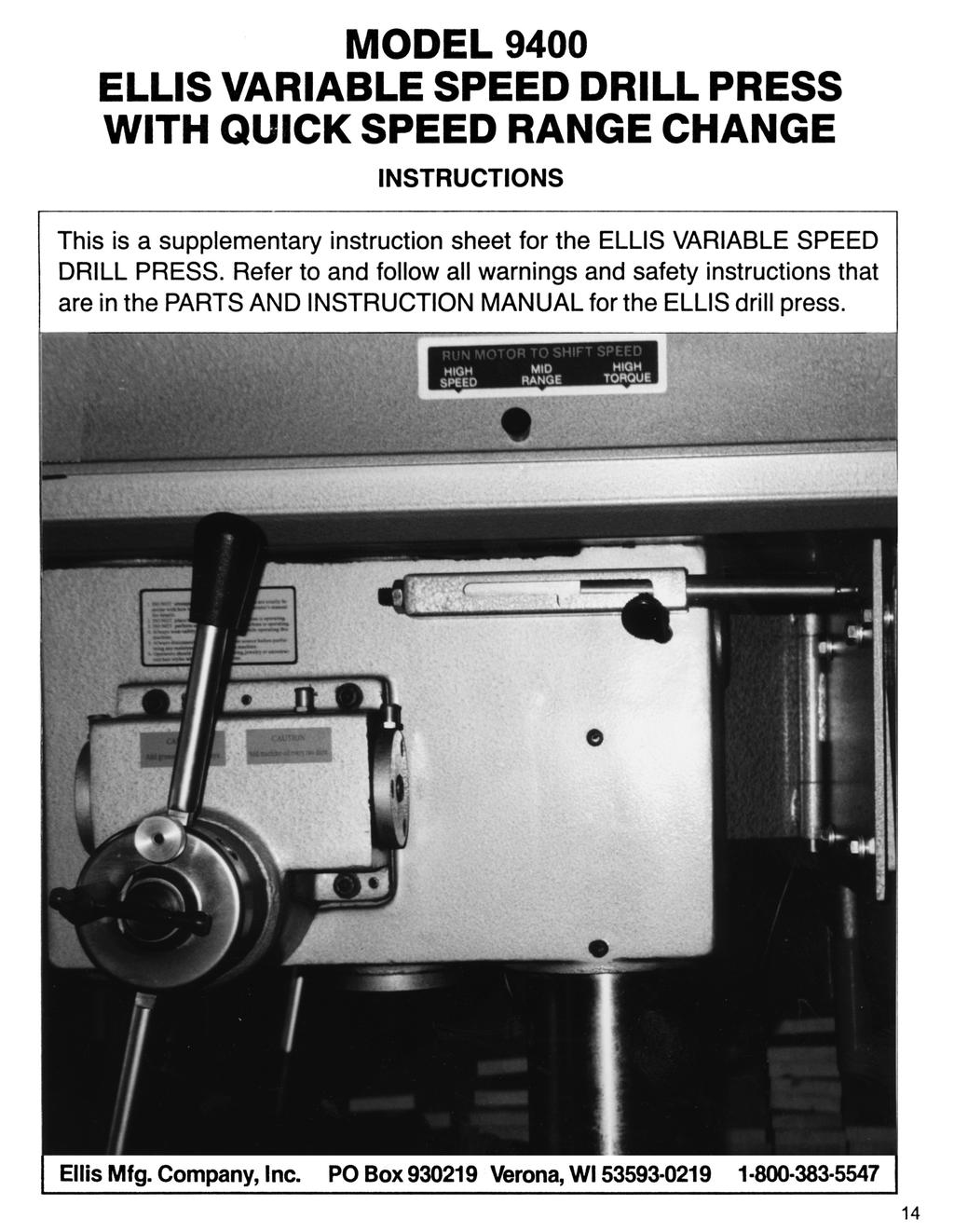
5 Diameter of column 4.0 Diameter of quill 3.0 Spindle travel 5.75 Spindle to table Maximum distance spindle nose to base surface Drills to center Motor 2 HP Net weight 675 LB Overall size 20 W x 29 D x 69.5 H SPEED CHANGE A quick Speed (Torque) Range change can be accomplished with the Ellis HI-Lo Handle on the right side of the machine. (See the enclosed instruction sheet.) Note: The motor must rotate at a moderate speed to change the operating speed range selection. The variable speed control can vary the speed infinitely within each speed (Torque) range setting which is explained in the next paragraph. VARIABLE SPEED CONTROL The Forward switch position is used for standard drilling and cutting operations. The Reverse switch position is used to retract a tap or for tapping left hand threads. Keep downward pressure on the feed handle when backing a tap out of the work. The Power Switch turns the machine ON when moved to the right, the green light goes on in the ON mode. The Speed knob controls the spindle speed from the stopped position and in both the forward and reverse mode. The Reset position stops the motor between changes in direction of rotation. To Stop the Drill Press return the Speed Dial to Zero. 4

6 Note: Avoid stalling the spindle and stopping the motor under power; the resulting current surge can damage the electronic components in the control box. Turn Power off immediately in a stalled motor condition. Clear the jam mechanically. Repeated stalling abuse is detectable and can lead to voiding the warranty. POWER TRAIN Spindle Speed The motor drives the middle pulley and the spindle pulley by a V-Belt. The spindle pulley drives the spindle and the taper sleeve. The spindle speed is variable by means of the variable speed control box or with the Ellis Hi-Lo handle. Forward and reverse rotation of the spindle is selected on the control box panel. If you have any problems with this, call the factory. Power Feed and Manual Feed Spindle feed can be accomplished in two modes: manual and by power. Manual Feed is accomplished by turning the turn style (8474) at the right side of the head stock. Pulling any of the two turn styles to the right engages the power feed and returning it to the left stops the power feed. The thumbscrew (7027) must be loosened to engage the power feed, and tightening this thumbscrew prevents the machine from actually engaging in the power mode. Use the power feed only when the spindle rotates in the CW (clockwise) rotation. Do not use power feed in the tapping mode. 5
 Stop the spindle rotation. Loosen the locking handle on the depth scale hub.")
7 DEPTH OF DRILLED HOLE Do not use the depth dial for through holes: unlock the locking clamp on the face of the depth dial. Proceed as described in the following for drilling holes to a preset depth: 1) Stop the spindle rotation. Loosen the locking handle on the depth scale hub. Lower the drill end to the desired drill depth by turning the turn style. Turn the dial CCW (counter clockwise) as you face the end of the turn style hub. Lock the locking clamp when the dial comes to a stop. 2) Note: When drilling through holes, place a block of wood or scrap piece of metal under the work piece to prevent drilling into the table or use an Ellis Safety Drill Press Vise. 3) The machine is equipped with a power feed overload clutch. The overload clutch protects the feed power train from damage if too high a feed rate or too high a spindle speed is used. The overload clutch disengages when you hear a clicking noise. Reduce the feed rate or spindle speed when this occurs. The overload torque at which the clutch disengages can be increased by turning the adjustment screws clockwise and can be decreased by turning the adjustment screw counterclockwise. There are two adjustment screws in the pulley groove at 180 degree from one another. Note: Do not tighten the screws too far because a solid spring cannot let the ball escape from the groove in the shaft. In this case the overload clutch would be rendered useless and damage can occur. To set the maximum torque: turn each set screw until tight and then back them out by two. 6
8 DRILL CHUCK AND TAPER SHANK DRILL ATTACHMENT The size of the taper to be used with this machine is a Morse # 3 Taper. It is important to wipe the inside taper in the spindle and the outside of the chuck taper or drill taper clean of oil or dirt. Insert the arbor into the spindle and twist to align the tang with the slot in the spindle then thrust upward sharply to seat the chuck. Follow the same procedure for a taper shank drill or accessory. A wood hammer can assist in doing this. REMOVING DRILL CHUCK OR DRILL FROM SPINDLE Loosen the locking handle on the depth scale collar. Lower the quill until the slot is completely uncovered. Grasp the locking handle and turn the collar CW (clockwise) as you face the end of the style handle body. Lock the handle securely when the collar comes against a stop. Turn the spindle until its slot lines up with the one in the quill. Insert the drift key into the slot. Hold the chuck or drill with one hand while tapping on the drift key with a hammer. DRILL SPEEDS AND USAGE. The speed at which the drill has to rotate for efficient cutting depends on the type of material being worked and the diameter of the drill. Use a squirt bottle to add cutting oil (fluid) to the drill. Retract the drill often when deep holes are drilled; this removes chips. Use a low Spindle Speed (Torque) for tapping a threaded hole. Use a heavy oil or thread cutting fluid to lubricate the tap. Reverse the spindle rotation with the reverse switch on the variable speed control panel to retract the tap. ELEVATING, ROTATING AND CLAMPING THE TABLE The table can rotate 360 degrees and move up and down on the column. Loosen both clamp screws, rotate the table in the required position, elevate the table by means of the elevation handle and tighten both clamp screws again. 7

9 LUBRICATION The power feed gear box at the right side of the head stock has several oil cups and grease fittings. Another grease fitting is at the left side near the sight window. LUBRICATION SCHEDULE 7027 Location Suggested Lubricant Frequency Oil Cups Machine Oil such as 10 wt 30 wt motor oil Daily or Twice Daily under heavy use Grease Nipple Lithium Grease N.L.G.I. # 2 Daily or Twice Daily under heavy use Under light use, oil and grease at least every other day. It is much more important that you grease and oil the machine frequently than to worry about the type of lubricant used. Do not mix synthetic and mineral base oils. 8
10 MAINTENANCE Keep table and sliding parts clean of dirt and chips. Every 3 months lower the quill, wipe clean and oil lightly. If raising the table becomes difficult, clean and wipe the column with light machine oil. The ball bearings in the motor, quill and V-Belt pulleys are lubricated for life. Keep the cooling fins of the speed control box and the motor clean and free of dirt and dust. The chart below identifies the bearings in the various locations. The Ellis Part Number is required for replacement orders. No. Bearing Part Location Type No. Size Qty. 1 Deep Grove Spline-Taper Sleeve x 75 x Deep Grove Quill x 55 x Ball Thrust Quill x 52 x Deep Grove Quill x 72 x Deep Grove Middle Sheave x 40 x Deep Grove Single Thread Worm x 40 x Deep Grove Single Thread Worm x 42 x Ball Thrust Bevel Gear x 28 x 9 1 9
11 PARTS LIST 10
12
13 12
14 TROUBLESHOOTING Problem Probable Cause Remedy Motor Does Not Run Power cord not plugged into source Plug into receptacle Power not ON at Speed Control Box Turn switch ON Speed knob in 0 position Turn knob CW for more speed One or both fuses are blown in speed control box Replace with fast blow ceramic fuse of same value Main switch fuse blown Replace fuse Motor too hot, heat switch tripped Wait for motor to cool off Power cord plugged into GFCI Protected outlet Plug into an unprotected outlet preferably a dedicated circuit of Power cord not plugged into correct outlet 20 amp, 115 VAC Power cord of a 115 V single phase machine has to be plugged into a 115 V outlet. A cord of a 230 single phase machine has to be plugged into a 230V outlet. Noisy Operation Incorrect belt tension Adjust tension Loose spindle or motor pulley Tighten set screw Belt is too tight Reduce belt tension Spindle bearing worn Replace spindle ball bearing Spindle Not Moving Up Return spring may be broken Replace spiral spring Drill Bit Smokes Or Is Burnt Incorrect speed Change speed Chips are not coming out of hole Retract bit frequently to clear out chips Dull drill bit Sharpen or replace drill bit Feed too slow Increase feed to allow bit to cut Needs lubrication Lubricate with cutting fluid Drill is running in reverse Change motor rotation Excessive Drill Run Out Bent drill Replace drill Chuck jaws not clamping evenly Install drill correctly Worn spindle bearings Replace ball bearings No Power Feed Worm gear worn Replace worm gear Overload protection device not working Tighten springs with set screws Pawl clutch is worn Replace pawls Feed belt is sliding Tighten belt Turn style does not move sideways Loosen thumb screw #7027 Hole Depth Not Correct Depth dial not clamped Tighten dial lock Worm gear or quill worn Replace gear Drill Not Rotating Taper on chuck slips in spindle Remove grease and oil from inside taper bore in spindle and outside of taper on chuck. Use mineral spirits. Spindle Not Rotating In Correct Rotation Switch on control box may not in be correct position Use forward switch for standard drilling and cutting. Use reverse switch to retract a tap or tapping for left-hand threads. 13
15
16 15
Ellis Drill Press Model 9400
 M f g. C o m p a n y, I n c. Ellis Drill Press Model 9400 Instruction Manual POWER FEED DRILL PRESS Infinitely Variable Speed Model 9400 Operation Manual July 16, 2010 Contents Page Number Preface 2 Installation
SB-32V Drill Press OWNERS MANUAL
 724 Robbins Road, Grand Haven, MI 49417 Phone: 616-842-7110 800-937-3253 Fax: 616-842-0859 800-846-3253 Web: www.dakecorp.com E-mail: customerservice@dakecorp.com SB-32V Drill Press OWNERS MANUAL FOR YOUR
TB & SB Series Drill Presses
 TB & SB Series Drill Presses OWNERS MANUAL BENCH AND FLOOR DRILL PRESS TB-16 Series & SB-16-25-32-Series FOR YOUR OWN SAFETY AND OPTIMUM OPERATION READ INSTRUCTION MANUAL BEFORE OPERATING DRILL PRESS RETAIN
Grizzly Drill Press SOP
 Grizzly Drill Press SOP Drill Press is wired to run on 0V. Drill Press has a built in light with a ON/OFF switch. Never hold a workpiece by hand while drilling. Clamp it down or hold it in a vice. Never
EllisSaw.com. EllisSaw.com P.O. Box Verona, WI
 P.O. Box 9019 Verona, WI 9-019 GENERAL OPERATING & SAFETY INSTRUCTIONS * READ INSTRUCTIONS BEFORE USE * CAUTION: Disconnect power supply cord from power source when doing repair work or changing belt.
FOR YOUR SAFETY: READ ALL INSTRUCTIONS CAREFULLY
 MODEL 2020F FOR YOUR SAFETY: READ ALL INSTRUCTIONS CAREFULLY Table of Contents General safety instructions for Power Tools 1 Main specification 2 Unpacking and checking contents 2 List of loose parts in
HOLE CUTTER SHARPENER ASSEMBLY & SERVICE MANUAL
 HOLE CUTTER SHARPENER ASSEMBLY & SERVICE MANUAL WARNING You must thoroughly read and understand this manual before operating the equipment, paying particular attention to the Warning & Safety instructions.
30X, 50X, 70X, 90X Safety And Operation Instructions
 30X, 50X, 70X, 90X Safety And Operation Instructions To Avoid Serious Injury And Ensure Best Results For Your Tapping Operation, Please Read Carefully All Operator And Safety Instructions Provided For
WARNING! Read and understand the entire instruction manual before attempting set-up or operation of this machine!
 ! WARNING! Read and understand the entire instruction manual before attempting set-up or operation of this machine! 1. This machine is designed and intended for use by properly trained and experienced
MI MI OPERATING MANUAL
 MODEL NO.: MI-76100 MI-76150 OPERATING MANUAL RULES for SAFE OPERATION MAGNUM INDUSTRIAL MI-76100 and MI 76150 DRILL PRESSES To help ensure safe operation, please take a moment to learn the how to operate
SAVE THIS FOR FUTURE REFERENCE THIS PRODUCT IS FOR PROFESSIONAL LABORATORY USE ONLY USER'S MANUAL
 DENTAL, INC. TECHNICAL BULLETIN Q827-022510 5860 FLYNN CREEK ROAD READ ALL INSTRUCTIONS P.O. BOX 106 BEFORE PROCEEDING COMPTCHE, CALIFORNIA, U.S.A. 95427 SAVE THIS FOR FUTURE REFERENCE www.wellsdental.com
REPAIR INSTRUCTIONS. Cat. No Cat. No MILWAUKEE ELECTRIC TOOL CORPORATION. SDS Max Demolition Hammer. SDS Max Rotary Hammer
 Cat. No. 9-0 SDS Max Demolition Hammer Cat. No. -0 SDS Max Rotary Hammer MILWAUKEE ELECTRIC TOOL CORPORATION W. LISBON ROAD BROOKFIELD, WISCONSIN 00-0 8-9-0 d 000 8-9-0 d Special Tools Require Forcing
SECTION 9: PARTS. G7947 Stand & Table Breakdown 4V2
 SECTION 9: PARTS G7947 Stand & Table Breakdown 19 15 21 18 16 17 112 5 113 3 14 8 7 6 6-1 13 4V2 12 116 11 9 10 2 114 115 1 We do our best to stock replacement parts when possible, but we cannot guarantee
17 Floor Drill Press. Operator s Manual. Record the serial number and date of purchase in your manual for future reference.
 30-230 17 Floor Drill Press Operator s Manual Record the serial number and date of purchase in your manual for future reference. Serial Number: Date of purchase: For technical support or parts questions,
SAVE THIS FOR FUTURE REFERENCE THIS PRODUCT IS FOR PROFESSIONAL LABORATORY USE ONLY USER'S MANUAL
 DENTAL, INC. TECHNICAL BULLETIN G801-022510 5860 FLYNN CREEK ROAD READ ALL INSTRUCTIONS P.O. BOX 106 BEFORE PROCEEDING COMPTCHE, CALIFORNIA, U.S.A. 95427-0106 SAVE THIS FOR FUTURE REFERENCE www.wellsdental.com
Tube Facing Tool.
 www.swagelok.com Tube Facing Tool This manual contains important information for the safe and effective operation of the Swagelok TF72 series tube facing tool. Users should read and understand its contents
MODEL T " SPIRAL CUTTERHEAD INSTALLATION INSTRUCTIONS
 MODEL T27449 8" SPIRAL CUTTERHEAD INSTALLATION INSTRUCTIONS The Model T27449 indexable insert spiral cutterhead is designed to replace the straightknife cutterhead on the Grizzly jointer Model G0490W/G0490XW
PARTS. W1669 & W1670 Parts PARTS. Model W1669/W1670 (For Machines Mfd. Since 04/18) 66V A A A 28A
 66V A A A 28A") W1669 & W1670 Parts 23 66V2 22 21 25 26 53A 62 63 89 64 9 65 24 20 15 16A 54 93 10 16A-1 81 77 94 53 79 102 103 28 36 8 30 19 31 32 32-1 109 28A 28 27 34 33 56 49 76 76 19-3 19-1 19-2 38-1 89 35 60 59
W1669 & W1670 Parts 23 66V2 22 21 25 26 53A 62 63 89 64 9 65 24 20 15 16A 54 93 10 16A-1 81 77 94 53 79 102 103 28 36 8 30 19 31 32 32-1 109 28A 28 27 34 33 56 49 76 76 19-3 19-1 19-2 38-1 89 35 60 59
Lassco Spinnit EBM-S Paper Drill
 Lassco Spinnit EBM-S Paper Drill User's Manual Provided By http://www.mybinding.com http://www.mybindingblog.com Before operating this equipment, please read these instructions completely and keep these
Yellow & Green may require a fuse smaller than 13 amps for certain products (subject to below).
.") INSTRUCTIONS FOR: Pillar drills MODEL No's: GDM120B, GDM160F Thank you for purchasing a Sealey product. Manufactured to a high standard this product will, if used according to these instructions and properly
INSTRUCTIONS FOR: Pillar drills MODEL No's: GDM120B, GDM160F Thank you for purchasing a Sealey product. Manufactured to a high standard this product will, if used according to these instructions and properly
18500 PORTABLE ELECTRIC POWER DRIVE
 18500 PORTABLE ELECTRIC POWER DRIVE PRODUCT INFORMATION AND OPERATING INSTRUCTIONS: Description: Widder 18500 Portable Electric Power Drive is an electric-motor-driven, heavy-duty power drive which provides
VARIABLE SPEED WOOD LATHE
 MODEL MC1100B VARIABLE SPEED WOOD LATHE INSTRUCTION MANUAL Please read and fully understand the instructions in this manual before operation. Keep this manual safe for future reference. Version: 2015.02.02
MUELLER E-5TM. and D-5TM. Drilling Machines. Reliable Connections. E-5 General Information 2. D-5 General Information 3. Operating Instructions 4-5
 operation Instructions manual MUELLER E-5TM and D-5TM TAble of contents PAGE E-5 General Information 2 Drilling Machines D-5 General Information 3 Operating Instructions 4-5 E-5 Parts 6 D-5 Parts 7! WARNING:
18600 PORTABLE POWER DRIVE THREADER PRODUCT INFORMATION AND OPERATING INSTRUCTIONS:
 WIDDER TOOLS 18600 PORTABLE POWER DRIVE THREADER PRODUCT INFORMATION AND OPERATING INSTRUCTIONS: Description: The 18600 Portable Electric Threader is an electric-motor-driven, heavy-duty power drive which
VARIABLE SPEED WOOD LATHE. Model DB900 INSTRUCTION MANUAL
 VARIABLE SPEED WOOD LATHE Model DB900 INSTRUCTION MANUAL 1007 TABLE OF CONTENTS SECTION...PAGE Technical data.. 1 General safety rules....1-3 Specific safety rules for wood lathe.....3 Electrical information.4
Inventory (Figure 2)
") MODEL T10127 12" SPIRAL CUTTERHEAD INSTRUCTIONS The Model T10127 indexable insert spiral cutterhead is designed to replace the straightknife cutterhead from the Grizzly jointer Model G0609. The total procedure
MODEL T10127 12" SPIRAL CUTTERHEAD INSTRUCTIONS The Model T10127 indexable insert spiral cutterhead is designed to replace the straightknife cutterhead from the Grizzly jointer Model G0609. The total procedure
SECTION 9: PARTS Main Breakdown
 SECTION 9: PARTS Main Breakdown 2 115 75 113 112 8 9 7 8 11 4 5 3 3 85 81 79 78 90 84 68 69 69 68 87 86 86 91 95 98-2 98-1 98-3 98-4 98 98-8 98-9 98-5 98-6 99 97 98-7 100 92 114 108 107 110 109 111 104
Looking for a small band saw? The Ellis 1100 band saw might be just what you are looking for.
 1100 MITRE BAND SAW Looking for a small band saw? The Ellis 1100 band saw might be just what you are looking for. This portable band saw moves easily to the job site. Use it as horizontal or vertical saw.
Horizontal and Vertical. Metal Cutting Band Saw MODEL: BS-115
 Horizontal and Vertical Metal Cutting Band Saw MODEL: BS-5 SAFETY. Know your band saw. Read the operator s Manual carefully. Learn the operations, applications and limitation.. Use recommended accessories.
Safety And Operation Instructions RSR50 VMC Right Angle Self-Reversing Tapping Units
 Safety And Operation Instructions To Avoid Serious Injury And Ensure Best Results For Your Tapping Operation, Please! Read Carefully All operator and safety instructions provided for this tapping attachment
SECTION 9: PARTS. Headstock
 SECTION 9: PARTS We do our best to stock replacement parts when possible, but we cannot guarantee that all parts shown are available for purchase. Call (800) 52-4777 or visit www.grizzly.com/parts to check
Maintenance Information
 16601023 Edition 2 January 2014 Air Impact Wrench 2705P1 Maintenance Information Save These Instructions Product Safety Information WARNING Failure to observe the following warnings, and to avoid these
# R8 Mill Instruction Manual. Please read and understand all instructions before using this tool.
 #8460 R8 Mill Instruction Manual Please read and understand all instructions before using this tool. Note: These instructions will show you how to assemble this machine, work its controls and maintain
MODEL H " BYRD SHELIX CUTTERHEAD INSTRUCTIONS
 MODEL H9291 12" BYRD SHELIX CUTTERHEAD INSTRUCTIONS The Model H9291 12" Byrd Shelix cutterhead is designed to replace the straight-knife cutterhead on the Grizzly jointer Model G0609. The total procedure
GEARED HEAD DRILL / MILL MACHINE INSTRUCTION MANUAL
 www.industrialtool.com.au GEARED HEAD DRILL / MILL MACHINE INSTRUCTION MANUAL READ CAREFULLY AND UNDERSTAND THESE INSTRUCTIONS BEFORE USE. LIMITED WARRANTY Industrial Tool & Machinery Sales (hereinafter
30DC Speed Lathe Manual
 30DC Speed Lathe Manual The Crozier Model 30DC Speed Lathe is our most popular model. It has many standard features not found on any other machine in its class or price range. Standard Features 3/4 HP
MODEL NO.: MI PARTS BREAKDOWN
 MODEL NO.: MI-76350 PARTS BREAKDOWN MAGNUM DRILL PRESS ASSEMBLY INSTRUCTIONS MODEL MI-76350 Before you begin to assemble your drill press, review the parts breakdown and keep it ready for reference. Start
 GENERAL OPERATIONAL PRECAUTIONS WARNING! When using electric tools, basic safety precautions should always be followed to reduce the risk of fire, electric shock and personal injury, including the following.
7th/8th Grade Industrial Tech General Safety. Give your undivided attention to the machine in which you are using.
 7th/8th Grade Industrial Tech General Safety Wood Lab Safety General Safety Always wear safety glasses. Report all injuries to the instructor. No baggy clothing or open toed shoes. Give your undivided
30AUTO Speed Lathe Manual
 30AUTO Speed Lathe Manual Standard Features 3/4 HP Motor Air-Collet Closure 1800 RPM, Single Speed Electric Brake Cast Housing 5C Collets 3 Phase / 240 Volts DESCRIPTION: The Crozier Model 30AUTO Automotive
Inventory (Figure 2)
") MODEL T10130/T10126 6" & 8" SPIRAL CUTTERHEAD INSTRUCTIONS The Model T10126/T10130 indexable insert spiral cutterheads are designed to replace straightknife cutterheads from the Grizzly jointer Models
MODEL T10130/T10126 6" & 8" SPIRAL CUTTERHEAD INSTRUCTIONS The Model T10126/T10130 indexable insert spiral cutterheads are designed to replace straightknife cutterheads from the Grizzly jointer Models
Due to possible damage in shipping, the vertical stop assembly has been removed from this machine.
 Due to possible damage in shipping, the vertical stop assembly has been removed from this machine. To assemble, insert the threaded rod through the shroud opening in the top of the machine. Start the four
LS12/LS12C. LS12C Item # LS12 Item # /10 LORTONE, inc Cyrus Way, Mukilteo, WA U.S.A
 LORTONE LS12C Item # 053-093 LS12 Item # 053-090 LS12/LS12C Instructions and Parts List The LS12 is a quiet, fully enclosed, professional quality 12 slab saw. It comes equipped with a powerful screw-feed
3-Phase Motor Spindle Group
 1 Disclaimer TOWNLABS does not make any representations, warranties or guarantees express or implied, as to the accuracy or completeness of the Manual. Users must be aware that updates and amendments will
Machining Laboratory Regulations and Safety
 Machining Laboratory Regulations and Safety General Laboratory Regulations Each person using the manufacturing laboratory is expected to comply with the following rules and regulations failure to do so
Inventory MODEL T10096 TAPER ATTACHMENT FOR G0509 & G0509G LATHE INSTRUCTIONS. Inventory (Figure 1) Needed Items
 Needed Items") MODEL T10096 TAPER ATTACHMENT FOR G0509 & G0509G LATHE INSTRUCTIONS Inventory The Model T10096 taper attachment was carefully packed when it left our warehouse. If you discover it is damaged after you
MODEL T10096 TAPER ATTACHMENT FOR G0509 & G0509G LATHE INSTRUCTIONS Inventory The Model T10096 taper attachment was carefully packed when it left our warehouse. If you discover it is damaged after you
SECTION 9: PARTS G7945/G7946
 SECTION 9: PARTS G7945/G7946 Main Parts 22 53 25 26 31 139 32 32-1 60 38 59 38-1 119 35 37 31 38-3 124 125 45A-2 45A-4 45A-1 31 60 45A-3V2 120 121 62 28 28-1 28 27 34 50 51 39 41 126 137 36 46 40 63 33
Lassco Spinnit EBM-2.1 Paper Drill
 Lassco Spinnit EBM-2.1 Paper Drill User's Manual Provided By http://www.mybinding.com http://www.mybindingblog.com Serial Number: Date of Purchase: Dealer: Address: Before operating this equipment, please
Trautman Carvers. Product Manual
 Trautman Carvers Product Manual Contents Product Specifications.... 4 Operating Precautions.... 6 Floor Carver Use.... 7 Floor Carver Diagram.... 10 Trautman Motor Lift Assist.... 11 Use of the Lift Assist....
15 BENCH & FLOOR DRILL PRESSES
 10/2016 15 BENCH & FLOOR DRILL PRESSES MODEL: KC-117N MODEL: KC-117FN INSTRUCTION MANUAL COPYRIGHT 2016 ALL RIGHTS RESERVED BY KING CANADA TOOLS INC. WARRANTY INFORMATION 2-YEAR LIMITED WARRANTY FOR THIS
HARDINGE Installation booklet For: Dead-Length Collet Adaptation Chucks Stationary Collet
 HARDINGE Installation booklet For: Dead-Length Collet Adaptation Chucks Stationary Collet Read the enclosed instructions and recommendations before any installations CONTENTS Dead-Length Collet Adaptation
Tapping Screw (W/Flange) 46 Cord Armor 47 Tube (D) 48 Cord. 45 Cord Clip. Tapping Screw (W/Flange) 10 Gear Cover Ass'y. 12 Socket (B) Ass'y
 46 Cord Armor 47 Tube (D) 48 Cord. 45 Cord Clip. Tapping Screw (W/Flange) 10 Gear Cover Ass'y. 12 Socket (B) Ass'y") W8VB The exploded assembly drawing should be used only for authoized service center. W8VB Item No. Part time 1 Magnetic Hex. Socket 2 Sub Stopper 3 O-Ring (S-16) 4 Locator (A) 5 Lock Sleeve (A) 6 O-Ring
W8VB The exploded assembly drawing should be used only for authoized service center. W8VB Item No. Part time 1 Magnetic Hex. Socket 2 Sub Stopper 3 O-Ring (S-16) 4 Locator (A) 5 Lock Sleeve (A) 6 O-Ring
Model: SCD430 SCD640. Installation & Operation Guide P/N SCD640-95
 Model: SCD430 SCD640 Installation & Operation Guide P/N SCD640-95 Model SCD430 and SCD640 Kurt has two Self-Centering vises, a four-inch jaw width (SCD430) and a six-inch jaw width (SCD640). Jaw opening
SALES CUSTOMER SERVICE TECHNICAL ASSISTANCE CALL TOLL-FREE:
 DENTAL, INC. TECHNICAL BULLETIN U802-022510 5860 FLYNN CREEK ROAD READ ALL INSTRUCTIONS P.O. BOX 106 BEFORE PROCEEDING COMPTCHE, CALIFORNIA, U.S.A. 95427 SAVE THIS FOR FUTURE REFERENCE THIS PRODUCT IS
6 BLADE CUTTER MODEL # PCC-6 OPERATION MANUAL
 4511 WAYNE AVENUE PHILADELPHIA PA 19144 TEL: 888-800-2663 FAX: 800-582-9643 6 BLADE CUTTER MODEL # PCC-6 OPERATION MANUAL CONTENTS I. INTRODUCTION TO BOND PCC-6 / MACHINE SPECIFICATIONS II. SAFETY PRECAUTIONS
D3 DRILL INSTRUCTION & PARTS MANUAL
 D3 DRILL INSTRUCTION & PARTS MANUAL Baumfolder Corp., 2003 Printed in U.S.A 1 TP10429A BAUMFOLDER CORPORATION 2003 All Rights Reserved WARNING Do not operate this machine without all guarding in place.
MODEL T " HELICAL CUTTERHEAD INSTALLATION INSTRUCTIONS
 MODEL T27696 12" HELICAL CUTTERHEAD INSTALLATION INSTRUCTIONS For questions or help with this product contact Tech Support at (570) 546-9663 or techsupport@grizzly.com Introduction The Model T27696 indexable
MUELLER GAS. DH-5 Drilling Machine. For use on 1 1 /2 & 2 Line Stopper Fittings. Reliable Connections. General Information 2
 operating Instructions manual MUELLER GAS TAble of contents PAGE DH-5 Drilling Machine For use on 1 1 /2 & 2 Line Stopper Fittings General Information 2 Installing and Stopping-off 1 1 /2 and 2 Line Stopper
Read carefully and follow all safety rules and operating instructions before first use of this product.
 operating manual & parts list 80161 & 70104 MILL DRILL AND STAND Read carefully and follow all safety rules and operating instructions before first use of this product. 2095.09-050 Palmgren Operating Manual
ROTARY HAMMER OWNER S MANUAL
 ROTARY HAMMER OWNER S MANUAL WARNING: Read carefully and understand all ASSEMBLY AND OPERATION INSTRUCTIONS before operating. Failure to follow the safety rules and other basic safety precautions may result
INSTRUCTION BOOK AND PARTS LIST
 Rag Cutter MODEL WE WARNING This machine is equipped with a very sharp knife. Keep hands, arms, and hair away from the knife area at all times. Misuse of this machine or failure to follow all safety instructions
Spinnit EBM -S Manual Paper Drill
 Spinnit EBM -S Manual Paper Drill R USER S MANUAL Before operating this equipment, please read these instructions completely and keep these operating instructions for future reference. Serial Number: Date
Assembly Instructions and Parts Manual 5C Collet Closer for GHW Lathes Model CC-GHW
 Assembly Instructions and Parts Manual 5C Collet Closer for GHW Lathes Model CC-GHW JET 427 New Sanford Road LaVergne, Tennessee 37086 Part No. M-321519 Ph.: 800-274-6848 Revision G1 03/2014 www.jettools.com
MUELLER GAS. DH-5/EH-5 Drilling. Reliable Connections. DH-5 Drilling Machine General Information 2. EH-5 Drilling Machine General Information 3
 operating Instructions manual MUELLER GAS TAble of contents PAGE DH-5 Drilling Machine General Information 2 DH-5/EH-5 Drilling EH-5 Drilling Machine General Information 3 Operating Instructions 4-5 DH-5
Ideal 1000 Manual
 Ideal 1000 Manual 20016-6111 Contents 1. Introduction.................................................................... 2 1.0 Introduction................................................................
SMALL GAUGE NIBBLER ASSEMBLY & OPERATING INSTRUCTIONS Mission Oaks Blvd., Camarillo, CA Visit our Web Site at
 SMALL GAUGE NIBBLER 91739 ASSEMBLY & OPERATING INSTRUCTIONS 3491 Mission Oaks Blvd., Camarillo, CA 93011 Visit our Web Site at www.harborfreight.com Copyright 2004 by Harbor Freight Tools. All rights reserved.
1. Turn off or disconnect power to unit (machine). 2. Push IN the release bar on the quick change base plate. Locking latch will pivot downward.
. 2. Push IN the release bar on the quick change base plate. Locking latch will pivot downward.") Figure 1 Miniature Quick Change Applicators, of the end feed type, are designed to crimp end feed strip terminals to prestripped wires. Each applicator is set up to accept the strip form of certain specific
Figure 1 Miniature Quick Change Applicators, of the end feed type, are designed to crimp end feed strip terminals to prestripped wires. Each applicator is set up to accept the strip form of certain specific
TurncrafterPlus. Variable Speed Mini Wood Lathe. User s Manual #TCLPLUS PRODUCT NO.
 TurncrafterPlus Variable Speed Mini Wood Lathe PRODUCT NO. #TCLPLUS User s Manual SPECIFICATIONS OF TURNCRAFTER PLUS MINI LATHE Model number:..............................................#tclplus Motor:......................................0V
 Operating Instructions Table of Contents Warranty & Safety Guidelines 2 Setup Instructions 3-4 Settings 5 Parts List 6 Troubleshooting 7 Assembly Instructions 8 Clamp Application Free-End 9-10 Preformed
24" x 24" OSCILLATING SPINDLE MANUAL
 24" x 24" OSCILLATING SPINDLE MANUAL LAGUNA TOOLS 2072 Alton Parkway Irvine, California 92606 Ph: 800.234.1976 www.lagunatools.com 2018, Laguna Tools, Inc. LAGUNA and the LAGUNA Logo are the registered
ELECTRIC TUBE ROLLER
 41238-0000 ELECTRIC TUBE ROLLER OPERATING INSTRUCTIONS & SERVICE MANUAL Rev: A, 8/20/2007 TO REDUCE THE RISK OF INJURY AND EQUIPMENT DAMAGE USER MUST READ AND UNDERSTAND OPERATOR S MANUAL. Thomas C. Wilson,
HCT908. Operating and Maintenance Instructions Manual. Variable Speed Hole-Cutting Tool
 R Operating and Maintenance Instructions Manual HCT908 Variable Speed Hole-Cutting Tool Before operating or servicing the HCT908 Hole-Cutting Tool, read all instructions in this manual and all warning
OPERATION AND MAINTENANCE HANDBOOK D407270XA
 OPERATION AND MAINTENANCE HANDBOOK D407270XA vers. 1.0 Thank you for choosing one of Silca s high quality key cutting machines. This machine has been designed, tested and produced in our factory using
Model SQM-2AC Squaring Module Rev TABLE OF CONTENTS
 92-0714 Rev. 970428 Model SQM-2AC Squaring Module TABLE OF CONTENTS CUSTOMER MESSAGE Inside Front Cover SAFETY PRECAUTIONS 3 GENERAL DESCRIPTION 6 SPECIFICATIONS 7 MAINTENANCE 8 OPERATION 9 CUTTING SPEEDS
STUDENT/FACULTY MACHINE SHOP SAFETY RULES
 STUDENT/FACULTY MACHINE SHOP SAFETY RULES Supervisors have full authority over the shop and its safe use, including the responsibility, authority, and obligation to prohibit shop or tool access for the
MODELS CSU 30 CSU 32AC CSU 32RL CSU 50AC CSU 50RL MDM 40 ELECTRIC MAGNETIC DRILLS OPERATING MANUAL
 MODELS CSU 30 CSU 32AC CSU 32RL CSU 50AC CSU 50RL MDM 40 ELECTRIC MAGNETIC DRILLS OPERATING MANUAL Table of Contents 1-1 Table of contents 2-1 Safety 3-1 Technical data 3-2 Items included in delivery 4-1
HAMMER DRILL OWNER S MANUAL
 HAMMER DRILL OWNER S MANUAL WARNING: Read carefully and understand all ASSEMBLY AND OPERATION INSTRUCTIONS before operating. Failure to follow the safety rules and other basic safety precautions may result
TURBO DRIVE INSTALLATION MODEL 1582T KNEE FEED Lagun Mill
 TURBO DRIVE INSTALLATION MODEL 1582T KNEE FEED Lagun Mill NOTE This Turbo Drive Knee Feed is configured for mounting the feed on the front of the knee with the keypad facing left. The lead screw pitch
Inventory MODEL H7937 TAPER ATTACHMENT FOR THE G0600 LATHE INSTRUCTIONS. Inventory (Figure 1) Needed Items
 Needed Items") MODEL H7937 TAPER ATTACHMENT FOR THE G0600 LATHE INSTRUCTIONS Inventory The Model H7937 taper attachment was carefully packed when it left our warehouse. If you discover it is damaged after you have signed
MODEL H7937 TAPER ATTACHMENT FOR THE G0600 LATHE INSTRUCTIONS Inventory The Model H7937 taper attachment was carefully packed when it left our warehouse. If you discover it is damaged after you have signed
POTENTIAL HEALTH & SAFETY HAZARDS
 Number: OH&S 18.48.1 Revision Date: 01/14/2015 Safe Operating Procedures for RIDGID 535 1. PURPOSE 1.1. To provide operational guidelines on the safe us of the RIGID 535 Pipe Threader used in the Trades
Model CBM-3 Counterbore Module Rev TABLE OF CONTENTS
 92-0227 Rev. 070529 Model CBM-3 Counterbore Module TABLE OF CONTENTS CUSTOMER MESSAGE Inside Front Cover SAFETY PRECAUTIONS 3 GENERAL DESCRIPTION 6 SPECIFICATIONS 7 MAINTENANCE 9 OPERATION 10 CUTTING SPEEDS
OPERATION AND MAINTENANCE FOR MODEL MRV050A REVERSIBLE
 OPERATION AND MAINTENANCE FOR MODEL MRV050A REVERSIBLE MANUAL AIR MOTOR 04666770 Edition 1 April, 1999 IMPORTANT SAFETY INFORMATION ENCLOSED. READ THIS MANUAL BEFORE OPERATING TOOL. FAILURE TO OBSERVE
Magnetic Base Drilling Machine A100/32. Operators Instruction Manual And Spare Parts Listings
 Magnetic Base Drilling Machine A100/32 Operators Instruction Manual And Spare Parts Listings Index Chapter 1. Technical Overview. Chapter 2. Warnings and Safety Instructions. Chapter 3. Operating Instructions.
BL500 Series Brake Lathes Variable and Single Speed Combination Lathes. Change from servicing rotors to drums in seconds!
 BL500 Series Brake Lathes Variable and Single Speed Combination Lathes Change from servicing rotors to drums in seconds! BL505 Combination Brake Lathe 11 9 10 1 4 2 BL505 shown with optional Digi-Cal Auto
4.4 PUMP MAINTENANCE MODELS: DB, DC, DF, DG, DJ, DL
 4.4 PUMP MAINTENANCE MODELS: DB, DC, DF, DG, DJ, DL 4.4.1 EXPLODED VIEW DRAWING REF. QTY. DB DC DF DG DJ DL DESCRIPTION PART # 1 1 ADAPTOR FRAME 034007 2 12 LOCK WASHER 3/8 x 1/8 S.S. 034004 3 12 HEX HEAD
ELECTRIC TOOL CORPORATION
 Cat. No. -0 / Hex Demolition Hammer Cat. No. 0-0 Spline Rotary Hammer MILWAUKEE ELECTRIC TOOL CORPORATION W. LISBON ROAD BROOKFIELD, WISCONSIN 00-0 -9-00 d 000 -9-00 d SpecialTools Require Forcing discs
Auto-Spreader Spreader HS10K Hydraulic Flange Spreader
 Auto-Spreader Spreader HS10K Hydraulic Flange Spreader US Patent No. 5678293 Operation and Maintenance Manual Keep For Your Records Contents Operation...2 Maximum Spreader Extension...3 Safety Tips...4
15 HEAVY DUTY BENCH AND FLOOR MODEL DRILL PRESS
 operating manual & parts list 80155 and 80156 15 HEAVY DUTY BENCH AND FLOOR MODEL DRILL PRESS Read carefully and follow all safety rules and operating instructions before first use of this product. 32111.09-0910
V BELT DRIVEN DRILLING MACHINES HU 16-2 TOPLINE HU 16-4 TOPLINE
 V BELT DRIVEN DRILLING MACHINES HU 16-2 TOPLINE HU 16-4 TOPLINE 1 2 4 3 5 Fig. A - Main parts Fig. 1 Fig. 3 Fig. 2 2 CHANGES AND TYPING ERRORS RESERVED Fig. 4 Fig. 5 Fig. 7 Fig. 6 Fig. 8 Fig. 9 CHANGES
3-1/4 HP VARIABLE SPEED PLUNGE ROUTER
 IMPORTANT INFORMATION 2-YEAR LIMITED WARRANTY FOR THIS PLUNGE ROUTER KING CANADA TOOLS OFFERS A 2-YEAR LIMITED WARANTY FOR NON-COMMERCIAL USE. 3-1/4 HP VARIABLE SPEED PLUNGE ROUTER PROOF OF PURCHASE Please
Inventory (Figure 2)
") MODEL T24631 8" SPIRAL CUTTERHEAD Installation INSTRUCTIONS For questions or help with this product contact Tech Support at (570) 546-9663 or techsupport@grizzly.com Introduction The Model T24631 spiral
MODEL T24631 8" SPIRAL CUTTERHEAD Installation INSTRUCTIONS For questions or help with this product contact Tech Support at (570) 546-9663 or techsupport@grizzly.com Introduction The Model T24631 spiral
DRILLING CATALOG. GRAINGER.COM/CHOICE l Grainger
 DRILLING CATALOG GRAINGER.COM/CHOICE l 1.800.Grainger DRILL PRESSES BENCH fact sheet 8" BENCH DRILL PRESS Dayton's light duty drilling machine combines performance and economy into one. It s an ideal choice
MILLING \ DRILLING MACHINE
 MILLING \ DRILLING MACHINE MODEL 400HS/400S2F 400HC/400C2F 400-070620-R2 INSTRUCTION MANUAL ! WARNING! Some dust created by power sanding, sawing, grinding, drilling, and other construction activities
# x 12 Wood Turner s Lathe
 #86892 8 x 12 Wood Turner s Lathe Please read and understand all instructions before using this tool. Note: These instructions will show you how to assemble this machine, work its controls and maintain
13" Bench Drill Press
 Model: 30-120 13" Bench Drill Press Operator s Manual Record the serial number and date of purchase in your manual for future reference. Serial Number: Date of purchase: For technical support or parts
Powermatic Model 31A Combination Belt-Disk Sander
 OPERATING PROCEDURE FOR: Powermatic Model 31A Combination Belt-Disk Sander INTRODUCTION: The combination belt-disk sander is used to sand the edges of boards. It can be used to smooth the edge or to remove
H8508 Impact Wrench SERVICE MANUAL. Model (Serial Code FWN) Model (Serial Code FWP)
 Model (Serial Code FWP)") SERVICE MANUAL H8508 Impact Wrench Model 48755 (Serial Code FWN) Model 48760 (Serial Code FWP) Read and understand all of the instructions and safety information in this manual before operating or servicing
SERVICE MANUAL H8508 Impact Wrench Model 48755 (Serial Code FWN) Model 48760 (Serial Code FWP) Read and understand all of the instructions and safety information in this manual before operating or servicing
INSTALLATION OF WELLS SUPER QUICK CHUCK LEFT HAND ON RED WING LATHE
 DENTAL, INC. TECHNICAL BULLETIN Q824-022510 5860 FLYNN CREEK ROAD READ ALL INSTRUCTIONS P.O. BOX 106 BEFORE PROCEEDING COMPTCHE, CALIFORNIA, U.S.A. 95427 SAVE THIS FOR FUTURE REFERENCE www.wellsdental.com
variable speed Operating Manual & Parts List
 Operating Manual & Parts List 9680175 20" variable speed floor model Drill Press Read carefully and follow all safety rules and operating instructions before first use of this product. 9642169.01-0217
Instruction Manual 13MM DRILL PRESS. Model SROM1199. Our tool range has you covered for DIY. Whatever the job, make light work of it with MAKO tools.
 Instruction Manual 13MM DRILL PRESS Model SROM1199 Our tool range has you covered for DIY. Whatever the job, make light work of it with MAKO tools. PRODUCT FEATURES: 1. Pulley Cover 9. Feed Handle 2. Motor