12-16 Ft Wide Enclosure Assembly Guide
|
|
|
- Earl Allison
- 5 years ago
- Views:
Transcription

1 Ft Wide Enclosure Assembly Guide RM Products Ltd


2 Handling and Storage 2 P a g e


3 Handling and Storage: 3 P a g e
4 Before You Begin Contact RM Products Ltd at: to arrange an assembly review with an RM Assembly Consultant. Be sure to have your shop drawings and manual with you at the time of placing your call. 4 P a g e


5 Parts List: Si ze wi de Side wall Roof Panels End panel set Expander panel Gable Complete end wall 5 P a g e
6 Tools List: 1x extension cord(may require more based on distance to power supply 2x variable speed 3/8 drills (one cordless is a good option) 1x 1/2 drill bit with 3/8 shank 3x 5/16 drill bits for steel (not speed bore wood bits) 1x adapter for drill to accept sockets or electric impact gun 1x 3/4 deep socket 1x 7/16 deep socket 1x 1/2 deep socket 1x large 825 mil caulking gun 1x regular 300 mil caulking gun 2x 7 step ladders (taller ladders required for buildings over 9 high) 1x tape measure 1x 48 level (larger buildings may require a transit level) 2x 36 pry bars 6x large vise grip C clamps 1x double high set of scaffold 1x dead blow hammer 1x extendable fork lift 2x 20 x 3 slings 1x 4 sling with hook To Speed Things Up: 1 electric man lift in place of scaffolding 1 electric or pneumatic impact wrench for tightening hardware 1 cordless drills for drilling small holes and installing smaller hardware General Man Power Requirements: On buildings 8-10 wide, a minimum of 2 people would be required. On buildings wide, a minimum of 3 people would be required. On buildings20 wide and buildings taller than 9 high, a minimum of 4 people would be required. 6 P a g e


7 New hardware list page: Use for bolting end panel internal flanges together. ¼-20 x 1 hex cap bolt and ¼-20 serrated flange nut. Use for bolting side wall panel internal flanges together. ½-13x2 hex cap bolt, ½ ID x 2 OD washer (2) and ½-13 hex nut. Use for bolting end panels to side walls. ¼-20 x 1-1/2 carriage bolt and ¼-20 serrated flange nut. Use for bolting side walls to fiberglass angle. ¼-20 x 2-1/2 carriage bolt, 5/16 ID x 1-1/2 OD washer and ¼-20 serrated flange nut. 7 P a g e
8 Maintenance: RM Products Ltd fiberglass modular structures are VIRTUALLY MAINTENANCE FREE! However VIRTUALLY does not equal COMPLETELY. To ensure that the RM Products Ltd fiberglass modular structure lasts its lifetime follow these few steps: Step 1: In case of heavy snow load or large amount of snow followed by a quick freeze, removing excess snow from the RM fiberglass building is recommended. The RM Products Ltd fiberglass building is engineered to meet snow loads of 100 lbs per square foot. That s a great deal of snow, however there are times in areas of northern US and Canada where snow falls will exceed the 100 lbs per square foot and it is important to take the time to prevent excess snow build-up. Step 2: If damage to the building occurs that reveals a crack, dent or buckle of any of the panels, it is important to repair the panel. Cracks and dents in the fiberglass can affect the overall integrity of the building making it less able to withstand the wind and snow loads it was engineered for. Repairs are inexpensive and easy to do, for more information or to purchase a repair kit, contact Step 3: Door maintenance, please refer to the DBCI roll-up door guide for ongoing maintenance of the roll-up door. 8 P a g e


9 Fiberglass angle base: Install expanding foam gasket to the fiberglass angle before setting 9 P a g e


10 Panel Assembly: First Section: End Section: rreeeer Start with the end section. This will be the section with no holes on the one side. Line up the roof and side wall panels. Remember to keep everything flush. Note: End section has no hole on one side. Once the side panel is lined up with the roof panel, clamp it into place and install a ½ -13x2 hex cap bolt assembly through each of the pre-drilled holes between the two parts. Repeat this process for the side wall on the opposite side of the building. See next page for more details. 10 P a g e


11 Panel Assembly: First Section: End Section: 11 P a g e


12 Panel Assembly: First Section: End Section: Caulking and Taping: Once the roof and side panels are fastened together, do the following: 1. Caulk the joints where the panels meet. 2. Tape the joints where the panels meet. 3. Leave approximately a 1 untapped area on both ends of the panels. NOTE: DO NOT tape completely to the top and bottom. Predrill holes: Next step: The measurement points are 4 from the end, 16 from this point, 16 from point and 4 from the end. Drill the holes for the fastening that will be used for attaching the side panels to the angle base. 12 P a g e


13 Installing Safety Hooks: Safety hooks are installed approximately every 3 rd section. Review your drawings to assure they are installed at the proper locations. Installing Safety Hooks: Line up and clamp the safety hook roof sections together. Drill a 5/16 hole through the safety hook and one roof panel. Use a carriage bolt to secure the safety hook while securing the roof sections together. The 1 hole on the safety hook should line up with the predrilled hole in the roof flange. Installing Lifting Hooks: If your enclosure requires lifting hooks, please reference the separate installation guide on the last page. 13 P a g e


14 Panel Assembly: First Section: End Section: Preparing for lifting: Prepare for Lifting: Once the side panels and roof panels are fastened together. Attach a 2 x 4 wood spreader bar that is ½ longer than the width of the building. Example. a 20 wide building, the spreader bar should be /2. It should be attached so that it is flush with the outside of the side panels. This assures that the section will be stable and wider than the base. This allows for ease of placing the section onto the base. If lifting the sections with a forklift, please proceed to the next page. If lifting the sections by hand, please proceed to page P a g e


15 Panel Assembly: First Section: End Section: Lifting with a Forklift: When lifting the section with an extendable forklift, you must position the slings on your panels in the right position. It is very important that the right length of sling is used and the right attachment cable is used. Required: 2x 20 x 3 slings 1x 4 sling with hook The positioning of the sling is very important so as not to damage any of the components. 15 P a g e

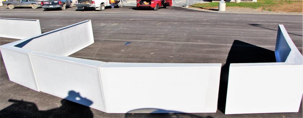
16 Panel Assembly: First Section: End Section: Setting the Sections on the base: When setting the first section on the base, it is crucial that the flange sits on the line that is marked on the base. Note: Every sections flange must sit on the line or the final section will not fit on the base. Once the flange is sitting on the mark, then drill a hole though the predrilled hole on the side panel and through the fiberglass angle then bolt in place. Undo the 2 x 4 spreader to fasten the other side panel to the base. NOTE: Hardware used is the ¼-20 x2-1/2 stainless steel carriage bolt, 5/16 x 1-1/2 stainless washer and serrated flange nut. 16 P a g e
17 Panel Assembly: Installing End Walls Now that the end section is up, the end walls, expanders and gables are installed. When these components are fastened, the section will be rigid and ready for the remainder sections. Installing the end walls: Mark base at /8 1. Place a mark on the angle base at /8. This is measured from the outside of the base not the building. This mark will be to position the bolt flange of the end wall. 2. Line up the bolt flange of the end wall with this mark on the base. Install a 2-1/2 carriage bolt through the bottom of the panel into the base. Install carriage bolt through bottom of panel to base. 3. N e x t, move the side wall and roof assembly so the edge of the end wall panel lines up where the roof and side panel join at the top. Line up side and roof panel joint with end wall panel. 17 P a g e


18 Panel Assembly: End Wall Installing end walls: Drill 5/16 hole and install carriage bolts at premarked locations. Repeat for the opposite side. 4. Drill a 5/16 hole through the bolt flange and sidewall panel at the premarked locations. Once the holes are drilled, install a ¼ - 20x1-1/2 carriage bolt through each hole and tighten with a 1/4-20 serrated flange nut on the inside. 5. Repeat steps 1-4 on the other side. 18 P a g e


19 Panel Assembly: Expanders: Installing expanders and gable: 1. Set one of the expander panels in place; align so it is flush with the installed end panel using a dead blow hammer. 2. Clamp in place. 3. Drill the bolt flange approximately every 16 with a 5/16 hole. 4. Install a 1/4-20x1 hexcap bolt and nut. 5. Repeat on opposite side. 6. Install gable in the same manner. This panel will also have pre-marked indents to fasten to roof panel. Repeat for the opposite side. Repeat process for the gable installation. 19 P a g e


 and ½ -13 hex nut in the bottom predrilled holes.")

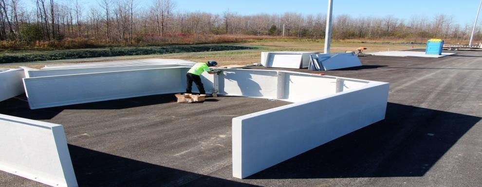
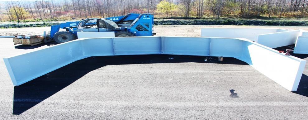
20 Panel Assembly: Middle Sections Setting the Middle Sections: When the end section and the end wall have been installed, the middle sections will be put in place. These sections have the predrilled holes on all flanges. Prepare for lifting the middle section the same as the end section. Note the location of your safety hooks so you set that section in the right location. Lifting and fastening the middle section to the base is the same as the first section, MAKE SURE that before you fasten the side panel that the flange is on the proper mark on the base. With one person outside, make sure that the flange is sitting on the line. Another person should be inside installing the ½ -13x2 hex cap bolt, ½ ID x 2 OD washer(x2) and ½ -13 hex nut in the bottom predrilled holes. The person on the outside should then install the carriage bolt and washer through the panel and the base. Repeat for the opposite side. When this is done the person on the scaffold or man lift should adjust the roof panel with a pry bar so the bottom of the roof is flush with the end section roof that has been installed then install 3 bolts per roof to hold roof in place. Once the roof panel is adjusted and bolted, the holes on side wall flanges of middle section should be lined up with the holes on the flanges of the end section side. A person on the outside using a blow hammer should be visually lining up the panels. When this is done a small number of bolts are used to fasten the middle section in place with the end section. Please follow bolt pattern indicated. Don t bolt all predrilled holes until building is up. 20 P a g e

21 Panel Assembly: Finished Look: Finished look: The sides should be flush with each other and line up on the roof line. The fronts should look like this. And line up like this. This is how the inside will look. 21 P a g e


22 Panel Assembly - Caulking and sealant: Caulking and sealant: Run a bead of caulking from the roof to the base of all the seams on the exterior. Make sure the bead is not just sitting on the surface but has penetrated the seams. THIS SHOULD BE DONE BY SOMEONE WITH EXPERIENCE. Run a bead of caulking from the roof to the base on all exterior seams. 22 P a g e


23 Panel Assembly Caulking and Sealant ***Where there are larger gaps along the roof panel seams RM Products Ltd recommends using spray foam instead of caulking to seal the gaps.*** This should be done by an experienced person as this is one of the most important tasks Step 1: Using the caulking supplied run a bead of caulking along all of the roof seams. Step 2: Adhere the 4 webseal roof tape over the seam with the building seams centered under the tape. Step 3: Smooth the tape out with your hand to ensure it is secure. Step 4: Apply with a paint brush the silicone roof sealant over the tape to seal in the seams of the tape. Allow to dry. 23 P a g e

24 Installing Doors and Windows: If you have requested a man door, the doors and hardware will be supplied. If you have requested a rollup door, please refer to the DBCI Roll-up door assembly guide for step by step instructions. 24 P a g e


25 Setting Sections without a Forklift: Lifting without a Forklift: When the building cannot be lifted with a forklift or when it is no taller than 11 feet tall and there are four persons working on the project the sections can be assembled into position without a forklift. Follow all instructions up to page 14. Prepare to lift onto the base by having three people guide the section up to the base. Place one person on each side panel. Make sure that when the section is lifted and sitting on the base that it is near the end of the base so it can be slid easily to the end. Lift and slide to the end of the base. Make sure it is snug to the end. 25 P a g e


26 Fastening the panels to the base: When the panel is snug to the end of the base and the spreader 2 x 4 is removed make sure the panels flange is on the marked line as described previously, bolt to the base using the lag bolts supplied into the predrilled holes. 26 P a g e


27 If the section is wider like a 14 or 16, use a 2 x 4 as a prop to help control the lift. Refer back to page 16 for remaining instructions. 27 P a g e


28 Installing Lifting Hooks Installing a Lifting Hook: First select one of the middle side panels where your lifting hook is going. Line up the top hole in the lifting eye over the top hole predrilled in the side panel. Drill a hole through the fiberglass panels using the lower hole on the lifting eye as your guide. When you have stood the two sections up that the lifting eye will be sandwiched in between, slide the lifting eye in and line up with the holes in the fiberglass panel. Install a bolt and washers in the top hole and predrilled holes in the side panel. Next, drill through the lower hole so that there is a hole through both side panels then install a bolt and washer here as well. 28 P a g e
12, 14 & 16 Wide Enclosure Assembly Guide
 www.rmfiberglass.com 12, 14 & 16 Wide Enclosure Assembly Guide RM Products Ltd 1-800-363-0867 www.rmfiberglass.com Table of Contents 1. Handling and Storage page 3 to 5 2. Parts and Tools List page 7 3.
8 Ft Wide Enclosure Assembly Guide
 www.rmfiberglass.com 8 Ft Wide Enclosure Assembly Guide RM Products Ltd 1-800-363-0867 www.rmfiberglass.com Table of Contents 1. Parts and Tools List page 3 2. Hardware page 4 3. Maintenance page 5 4.
Oval Vinyl Gazebo. Assembly Manual
 Oval Vinyl Gazebo Assembly Manual Gazebo Assembly Thank you for your purchase of this Gazebo. This manual is designed to simplify the assembly process, however we strongly recommend having an experienced
PAK Drum Roll Top Assembly Instructions. Note: 2 people will be required to assemble roll top
 PAK901 4 Drum Roll Top Assembly Instructions Note: 2 people will be required to assemble roll top PLEASE READ ASSEMBLY INSTRUCTIONS CARFULLY Tools required: 5/8 Socket & Ratchet 9/16 Deep Well Socket &
STRATUS SHELTER. Take bike parking to new heights
 Take bike parking to new heights The Stratus Shelter is a striking bike shelter option for any transit station, university campus, or multi-family residential building project. It is constructed of American
INSTALLATION GUIDE NS Double Clamp Ladder Rack NV200 / City Express ( Aluminum )
") INSTALLATION GUIDE 1530-NS Double Clamp Ladder Rack NV200 / City Express ( Aluminum ) QUICK START GUIDE Phase 1 - Assembly q 1.1 Setup... q 1.2 Ladder Rack Assembly... 3-5 5-13 Phase 2 - Installation q
INSTALLATION GUIDE 1530-NS Double Clamp Ladder Rack NV200 / City Express ( Aluminum ) QUICK START GUIDE Phase 1 - Assembly q 1.1 Setup... q 1.2 Ladder Rack Assembly... 3-5 5-13 Phase 2 - Installation q
176 S. New Holland Road Gordonville, PA Tel: Fax: Playhouse Loft
 176 S. New Holland Road Gordonville, PA 17529 Tel: 717-768-0066 Fax: 717-768-8569 A S S E M B LY M A N U A L Playhouse Loft Playhouse Loft revised 9/6/05 Assembly Manual Dear Customer, Thank you for your
MONKEY BARS OVERHEAD RACK INSTALLATION
 MONKEY BARS OVERHEAD RACK INSTALLATION Thank you for purchasing the New Monkey Bars Overhead storage rack. The most innovative overhead rack on the market WARNING THE PROPER INSTALLATION OF THIS STORAGE
Side DuraRac Installation Instructions
 Side DuraRac Installation Instructions Ford Transit Low Roof 130 /148 WB Frame Kit Part #: CRC 22-1010-002 V1.0.08.10.18 IMPORTANT INSTALLATION STEPS ARE DENOTED USING A STOP SIGN. THESE STEPS MUST BE
Installation Guidelines
 Page 1 Tools You ll Need 4 ft. Carpenter s level Chalk line (to mark U channel locations) Cordless drill/nut driver Caulking gun Chop saw with a metal cutting blade on it (required to make accurate and
Assembly Instructions 10 X 10 Aluminum Frame Building
 Assembly Instructions 10 X 10 Aluminum Frame Building 27 97 9 8 47 36 74 52 10 10 X 10 Square Building W/ Dome Includes: The Steel Entry Door with a Dead Bolt Lock assembly and Aluminum Door Frame. Metal
176 S. New Holland Road Gordonville, PA Tel: Fax: Castle Loft
 176 S. New Holland Road Gordonville, PA 17529 Tel: 717-768-0066 Fax: 717-768-8569 A S S E M B LY M A N U A L Castle Loft Castle Loft Assembly Manual revised 08/31/05 Dear Customer, Thank you for your purchase
3/4 Rear DuraRac Installation Instructions
 3/4 Rear DuraRac Installation Instructions Ford Transit Low Roof 130 WB Frame Kit Part #: CRC 27-1010-001 V1.0.09.28.18 IMPORTANT INSTALLATION STEPS ARE DENOTED USING A STOP SIGN. THESE STEPS MUST BE PERFORMED
CONTENTS TOOL LIST U P S I D E I N N O V A T I O N S, L L C RAMP AND STEP SYSTEM ASSEMBLY INSTRUCTIONS. Revised: June 2013
 U P S I D E I N N O V A T I O N S, L L C RAMP AND STEP SYSTEM ASSEMBLY INSTRUCTIONS TOOL LIST Required Tools: - Reciprocating Saw with Metal Cutting Blade - Drill - 7/16 Drill Bit for Metal Drilling -
Rear Mount Installation Instructions
 Rear Mount Installation Instructions Ford Transit Low Roof 130 WB Frame Kit Part #: DTC 0809-011 V1.0.10.12.18 IMPORTANT INSTALLATION STEPS ARE DENOTED USING A STOP SIGN. THESE STEPS MUST BE PERFORMED
Dodecagon Gazebo. Assembly Manual. If you are in the middle of your project and you need assistance Call (717)
") Dodecagon Gazebo Assembly Manual If you are in the middle of your project and you need assistance Call (717) 351-9250 Gazebo Assembly Manual Thank you for your purchase of this Gazebo. This manual is designed
Dodecagon Gazebo Assembly Manual If you are in the middle of your project and you need assistance Call (717) 351-9250 Gazebo Assembly Manual Thank you for your purchase of this Gazebo. This manual is designed
Introduction. Depending on your kennel project, you may have some or all of the following hardware: Part # Description Part # Description 1468
 Introduction Thank you very much for your investment in Mason kennels. We take great pride in providing our customers with the highest quality animal enclosures combined with an enjoyable ordering experience.
INSTALLATION INSTRUCTIONS 12' x 18' x 7' FRAME (12 x 20 x 7 ROOF COVERAGE) 2 SQUARE CARPORT
 2 SQUARE CARPORT") INSTALLATION INSTRUCTIONS 12' x 18' x 7' FRAME (12 x 20 x 7 ROOF COVERAGE) 2 SQUARE CARPORT Our unique assembly process quickly transforms the individual pieces into a finished structure that will give
INSTALLATION INSTRUCTIONS 12' x 18' x 7' FRAME (12 x 20 x 7 ROOF COVERAGE) 2 SQUARE CARPORT Our unique assembly process quickly transforms the individual pieces into a finished structure that will give
INSTALLATION GUIDE Locker With Top Shelf Transit Low Roof & Nissan NV Low Roof ( Aluminum )
") INSTALLATION GUIDE 7115 Locker With Top Shelf Transit Low Roof & Nissan NV Low Roof ( Aluminum ) QUICK START GUIDE Phase 1 - Assembly q 1.1 Setup... q 1.2 Locker w/ Top Shelf Assembly... 3-5 6-13 Phase
INSTALLATION GUIDE 7115 Locker With Top Shelf Transit Low Roof & Nissan NV Low Roof ( Aluminum ) QUICK START GUIDE Phase 1 - Assembly q 1.1 Setup... q 1.2 Locker w/ Top Shelf Assembly... 3-5 6-13 Phase
176 S. New Holland Road Gordonville, PA Tel: Fax: Summit Tower
 176 S. New Holland Road Gordonville, PA 17529 Tel: 717-768-0066 Fax: 717-768-8569 A S S E M B LY M A N U A L Summit Tower Summit Tower Assembly Manual revised 9/07/05 Dear Customer, Thank you for your
May 14, Installation Manual
 May 14, 2012 Installation Manual Contents MAG TRACKER Components...1 Mount Installation...7 Module Installation & Grounding...11 Maintenance...14 Warranty......14 Contact Information......14 May 14, 2012
SINGLE TRACK BYPASS (patent pending) barn door hardware
 barn door hardware") SINGLE TRACK BYPASS (patent pending) barn door hardware Installation Manual What is included in your kit: Part number Part name Quantity 1 Inner door hanger 2 2 Outer door hanger 2 3 5/16 x 1.5 lag bolts
SINGLE TRACK BYPASS (patent pending) barn door hardware Installation Manual What is included in your kit: Part number Part name Quantity 1 Inner door hanger 2 2 Outer door hanger 2 3 5/16 x 1.5 lag bolts
RBP-1215B-RX DODGE RAM QUAD CAB RX3
 RBP-1215B-RX3 2002-2017 DODGE RAM 15-3500 QUAD CAB RX3 Passenger side RX-3 Side Step Drill Template Passenger side rear Modular Bracket (6) L Support Brackets Driver side rear Modular Bracket Driver side
Locker Pedestal Installation Instructions
 Locker Pedestal Installation Instructions LK-PED-INST-0314r1 Parts List Single Pedestal Back to Back Pedestal Horizontal Support Tube TS-169 Post Flange TS-190 Post Cap Fasteners Provided: #8 x ¾ round
Aluminum Clad Wood Window 1/2 Reinforced Field Mulling and Stacking Supplement
 Aluminum Clad Wood Window 1/2 Reinforced Field Mulling and Stacking Supplement 1 Aluminum Clad Wood Window 1/2 Reinforced Field Mulling and Stacking Supplement The following instructions are a supplement
WK9 WORKTOP KIT Assembly Guide
 WK9 WORKTOP KIT Assembly Guide Tools and supplies needed for assembly: Cordless drill with #2 Phillips bit 5/16" drill bit #2 Phillips screwdriver Bubble level Sharp felt tip marker 3/8" and 7/16" wrenches
Balustrade Systems / Installation Instructions
 A. PARTS AND SUPPLIES NEEDED FOR INSTALLATION Hardware included for each 10 section of rail: 2 3 x 1-1/2 L-brackets 4 1-3/4 x 3/16 Blue hex-head screws for anchoring the L-brackets to the newel cap, column
Spring Loaded All Season Roll-Up Doors
 Spring Loaded All Season Roll-Up Doors STAND-OFF MOUNTING METHOD INSTALLATION INSTRUCTIONS READ THIS FIRST Carefully examine the crate(s) for damage before opening. If the carton is damaged, immediately
12x12 Pavilion. Assembly Manual
 12x12 Pavilion Assembly Manual 12x12 Pavilion Assembly Manual Congratulations on purchasing your new Pavilion. Thank You for your purchase and Welcome to the YardCraft Famiy. This manual is designed to
INSTALLATION GUIDE. C20-FTM STRAIGHT PARTITION Transit Partition ( Perforated Window, No Access, Steel )
") INSTALLATION GUIDE C20-FTM STRAIGHT PARTITION Transit Partition ( Perforated Window, No Access, Steel ) QUICK START GUIDE Phase 1 - Assembly q 1.1 Setup... q 1.1.1 Unpack components; compare with the bill
INSTALLATION GUIDE C20-FTM STRAIGHT PARTITION Transit Partition ( Perforated Window, No Access, Steel ) QUICK START GUIDE Phase 1 - Assembly q 1.1 Setup... q 1.1.1 Unpack components; compare with the bill
INSTALLATION INSTRUCTIONS LS X 12-2 X 7 1/2 FRAME LOAFING SHED
 INSTALLATION INSTRUCTIONS LS-12 12 X 12-2 X 7 1/2 FRAME ACTUAL FRAME BASE SIZE: 12 X 12-2 LOAFING SHED Our unique assembly process quickly transforms the individual pieces into a finished structure that
Ledger Board Lean-to Instruction Manual
 Ledger Board Lean-to Instruction Manual for 18 x 24 2 x 8 /12 6 covers ROOF ONLY ROOF WITH GABLES 2-SIDED FRAME ONLY 2-SIDED WITH GABLES Our unique assembly process quickly transforms the individual pieces
INSTALLATION GUIDE N5-DS48-4
 INSTALLATION GUIDE N5-DS48-4 Shelving ( steel ) Transit High Roof & Medium Roof Promaster Standard Roof & High Roof Nissan NV High Roof Sprinter Low Roof & High Roof Box Truck / Trailer QUICK START GUIDE
MTS-ACB. RENOGY Photovoltaic Module Adjustable Curved Bracket E Philadelphia St, Ontario, CA Version: 1.
 MTS-ACB RENOGY Photovoltaic Module Adjustable Curved Bracket 2775 E Philadelphia St, Ontario, CA 91761 1-800-330-8678 1 Version: 1.0 Important Safety Instructions Please save these instructions. This manual
General Prisoner Transport Install Instructions PT-2-INST
 General Prisoner Transport Install Instructions PT-2-INST 50 or 60 high x 80, 100 & 120 inch long / Double Compartment Inserts Also refer to PT-A-3XX instructions for vehicle specific mounting measurements
GIRTS ON BACK OF BUILDING
 GIRTS ON BACK OF BUILDING ALL GIRTS ARE 1 1/2 SQUARE TUBE. GIRT LENGTHS FOR 12, 20, 24, AND 30 WIDE BUILDINGS: ON 12 WIDE BUILDINGS GIRTS ARE 67 3/4 LONG ON 20 WIDE BUILDINGS GIRTS ARE 56 3/4 LONG ON 24
K9 KIT INSTALLATION INSTRUCTIONS CROWN VIC KK-K9-F7-K
 K9 KIT INSTALLATION INSTRUCTIONS 1998-2011 CROWN VIC KK-K9-F7-K TOOLS REQUIRED: Power Drill (Cordless preferable) Drill Bit Set Standard Wrench and Socket Set Metric Socket Set Screwdriver Set Torx Bit
UNIT 5: EXTERIOR DOORS AND WINDOWS
 KEY CONCEPTS 1. Identify tools needed for exterior door and window installation 2. Last step to weather proofing the home 3. Steps to installing exterior doors and windows 4. Maintenance and safety of
176 S. New Holland Road Gordonville, PA Tel: Fax: Eagles Nest
 176 S. New Holland Road Gordonville, PA 17529 Tel: 717-768-0066 Fax: 717-768-8569 A S S E M B LY M A N U A L Eagles Nest Eagles Nest Assembly Manual revised 9/2/05 Dear Customer, Thank you for your purchase
INSTALLATION INSTRUCTIONS KK-K9-C12-K CHEVY IMPALA
 INSTALLATION INSTRUCTIONS KK-K9-C12-K 2000-2005 CHEVY IMPALA READ ALL INSTRUCTIONS PRIOR TO INSTALLATION TOOLS REQUIRED: Power Drill Drill bits1/4 and 5/32 7/l6 wrench and socket 15,18 and\or 19mm socket
MTS-ZB. RENOGY Photovoltaic Module Z-Bracket Mounting System E Philadelphia St, Ontario, CA Version: 1.
 MTS-ZB RENOGY Photovoltaic Module Z-Bracket Mounting System 2775 E Philadelphia St, Ontario, CA 91761 1-800-330-8678 1 Version: 1.0 Important Safety Instructions Please save these instructions. This manual
Side Katerack Installation Instructions
 Side Katerack Installation Instructions Ram ProMaster City 2015+ Frame Kit Part #: CRC 28-1000-001 V1.0.12.06.18 IMPORTANT INSTALLATION STEPS ARE DENOTED USING A STOP SIGN. THESE STEPS MUST BE PERFORMED
Installation Guide. Step 3. Valley Flashing. Step 7. Transition Flashings and Accessories. Step 6. Hip and Ridge Installation
 Step 7. Transition s and Accessories Step 3. Valley Step 6. Hip and Ridge Installation Step 2. Rake Trim Step 5. Installing the Shingles Step 1. Eave Starter Installation Step 4. Endwall s Installation
Rear Katerack Installation Instructions
 Rear Katerack Installation Instructions Ram Promaster City 2015+ Frame Kit Part #: CRC 26-1000-001 V1.0.12.04.18 IMPORTANT INSTALLATION STEPS ARE DENOTED USING A STOP SIGN. THESE STEPS MUST BE PERFORMED
7 X 10 X 6 SHELTER 7 X 16 X 6 SHELTER 12 X 10 X 6 SHELTER 12 X 16 X 6 SHELTER
 ASSEMBLY INSTRUCTIONS FOR 7 X 10 X 6 AND 7 X 16 X 6 ATV SPORT SHELTER ACTUAL FRAME SIZES: 7 X 9-1 1/2 X 6 AND 7 X 13-7 1/2 X 6 AND 12 X 10 X 6 AND 12 X 16 X 6 ATV SPORT SHELTER ACTUAL FRAME SIZES: 12 X
Roof Only Lean-to Instruction Manual
 Roof Only Lean-to Instruction Manual for 10 x 20 2 x 8 /10 6 covers Our unique assembly process quickly transforms the individual pieces into a finished structure that will give you a lifetime of service.
Ledger Board Lean-to Instruction Manual
 Ledger Board Lean-to Instruction Manual for 18 x 24 2 x 8 covers Our unique assembly process quickly transforms the individual pieces into a finished structure that will give you a lifetime of service.
Metro Series Sauna. installation instructions
 Metro Series Sauna installation instructions Please immediately check for any hidden damage that may have occurred in shipping. If any damage is found you must notify the delivering carrier within seven
Installation Instructions
 Installation Instructions Follow these simple instructions to install your OneDayCab! IMPORTANT: Unpack and check shipment for damage. Verify color, size and parts before demolition. Installation of interiors
INS A KSR INSTALLATION INSTRUCTIONS STANDARD PROCEDURE. 1. Verify Curb Installation Required Installation Tools...
 INS-88.300-0A KSR INSTALLATION INSTRUCTIONS STANDARD PROCEDURE 1. Verify Curb Installation... 2 2. Required Installation Tools... 2 3. Unpacking the KSR... 3 4. Attach KSR Bottom Rail to Curb... 5 5. Attach
Santa Fe Cover INSTALLATION GUIDE. Alumawood TM Newport with MAXX Panel TM Installation Guide
 Alumawood TM Newport with MAXX Panel TM Installation Guide Santa Fe Cover INSTALLATION GUIDE Whatever the weather, you can enjoy the sophisticated charm of a lattice cover. The Santa Whatever the weather,
Installation Guide for Andersen Architectural Clad Inswing Entry and Patio Doors
 Installation Guide for Andersen Architectural Clad Inswing Entry and Patio Doors Congratulations! You have just purchased one of the many fine Andersen products. Proper assembly, installation and maintenance
INSTALLATION GUIDE. C30-NH STRAIGHT PARTITION Nissan NV ( Swing Door, Steel )
") INSTALLATION GUIDE C30-NH STRAIGHT PARTITION Nissan NV ( Swing Door, Steel ) QUICK START GUIDE Phase 1 - Assembly q 1.1 Setup... q 1.2 Partition assembly... 3 to 4 5 to 6 Phase 2 - Installation q 2.1 Tips
INSTALLATION GUIDE C30-NH STRAIGHT PARTITION Nissan NV ( Swing Door, Steel ) QUICK START GUIDE Phase 1 - Assembly q 1.1 Setup... q 1.2 Partition assembly... 3 to 4 5 to 6 Phase 2 - Installation q 2.1 Tips
AWNING / PATIO COVER INSTALLATION INSTRUCTIONS
 AWNING / PATIO COVER INSTALLATION INSTRUCTIONS Before You Begin Read the installation instructions thoroughly before beginning the installation procedure. Perspective In the Awning Instructions, Back means
Austin Standing Seam Awning Assembly and Installation Instructions. Assembly Instructions
 Austin Standing Seam Awning Assembly and Installation Instructions Be sure to use safety glasses when assembling and installing the awning. Some metal parts may have sharp edges. Use work gloves to handle
10X12 Arched Breeze Pergola Assembly Manual Outdoor Living Today
 10X12 Arched Breeze Pergola Assembly Manual Outdoor Living Today ITEM# BZ1012ARCH Revision 2 March 25th/2015 Note: Post Mounting Hardware is NOT included in this kit. Please confirm with your local building
INSTALLATION GUIDE SM SOLAR MOUNT PUB15JAN01
 MOUNT INSTALLATION GUIDE PUB5JAN0 SM SOLAR Wrenches and Torque Wrench Size Recommended Torque (ft-lbs) /4 Hardware 7/6 *0 3/8 Hardware 9/6 *30 # Hardware 5/6 0 Torques are not designed for use with wood
KIT ASSEMBLY INSTRUCTIONS
 KIT ASSEMBLY INSTRUCTIONS We have designed these instructions as a stepby step procedure to simplify the assembly process. Nevertheless, we do recommend including someone with carpentry expertise on your
INSTALLATION INSTRUCTIONS PART#:17GT23MSS\17GT23MA MODULAR GRILL GUARD FOR CHEVY SILVERADO 1/2 TON 99-02
 INSTALLATION INSTRUCTIONS PART#:17GT23MSS\17GT23MA MODULAR GRILL GUARD FOR CHEVY SILVERADO 1/2 TON 99-02 1 guard, center section 1 brush guard, left side 1 brush guard, right side 1 wire guard insert,
USER AND INSTALLATION MANUAL FOR THE BALNEA ENCLOSURE
 USER AND INSTALLATION MANUAL FOR THE BALNEA ENCLOSURE Warning: PLEASE ENSURE SNOW OR ICE REMOVAL OF STRUCTURE IN CASE OF EXCESS SNOW OR ICE FOLLOWING A STORM! FAILURE TO FOLLOW THESE PROCEDURES COULD RESULT
Octagon Vinyl Gazebo Assembly Instructions For 10 & 12 Models
 Octagon Vinyl Gazebo Assembly Instructions For 10 & 12 Models Toll Free: 866.768.8465 Hours: 9-5 Monday-Friday EST www.homeplacestructures.com Package ships as shown revised 04/29/09 Vinyl Gazebo Assembly
Katerack Wagon Shelving System
 Ford Transit Connect Assembly Installation Instructions Sheet 1 of 14 BEFORE YOU START! IMPORTANT INSTALLATION STEPS ARE DENOTED USING A STOP SIGN. THESE STEPS MUST BE PERFORMED IN THE SPECIFIED ORDER
Rolling Curtain door Manual
 Rolling Curtain door Manual Installation Maintenance parts Model 944 PHONE 800 448 8979 FAX 800 236 8722 website www.tracrite.com EMAIL tr@tracrite.com ADDRESS 216 Wilburn Road Sun Prairie, WI 53590 This
ROOF CURB INSTALLATION INSTRUCTIONS: VERTICAL STANDING SEAM PANEL
 : p: (800) 284-1412 f: (903) 759-3598 www.lmcurbs.com 827 fisher rd longview, tx 75604 Installation Check List: Attach Sub-Frames Layout Curb on Back-up Channels Apply Sealants & Set Curb in Place Fasten
Dura-Lock Roof System
 DLR-14 Dura-Lock Roof System Assembly and Installation Instructions Read the instructions before starting the job. They explain the steps required to produce a finished product that will meet factory specifications.
YUKON PATIO COVER INSTALLATION INSTRUCTIONS
 YUKON PATIO COVER INSTALLATION INSTRUCTIONS Before You Begin: Consult your local building department for any required permits You may be required to obtain a building permit for this structure. Contact
Austin Standing Seam Awning with Overhead Braces Assembly and Installation Instructions. Assembly Instructions
 Austin Standing Seam Awning with Overhead Braces Assembly and Installation Instructions Be sure to use safety glasses when assembling and installing the awning. Some metal parts may have sharp edges. Use
Salter Industries Spiral Stair
 Salter Industries Spiral Stair The Leader in Spiral Staircases Continuous Sleeve Stair Installation Instructions TOOLS NEEDED: 1. Electric drill with hex chuck and Phillips bit 2. Drill bits 1/8", 1/4",
Spring Loaded SCREEN-PRO. All Season Roll-Up Doors IN-JAMB MOUNTING METHOD INSTALLATION INSTRUCTIONS READ THIS FIRST
 Spring Loaded SCREEN-PRO All Season Roll-Up Doors IN-JAMB MOUNTING METHOD INSTALLATION INSTRUCTIONS READ THIS FIRST Carefully examine the crate(s) for damage before opening. If the carton is damaged, immediately
Important Notice. caution: Use proper lifting equipment and correct procedures to avoid injury.
 Integrity. Partnership. Quality. COMMERCIAL DOOR INSTALLATION INSTRUCTIONS SERIES 1900, 1950, 2000, 2250, 2500, 2750 Important Notice In the following text, the word: Warning: Indicates that serious injury
INSTALLATION GUIDE SM SOLAR MOUNT PUB15JUN15
 MOUNT INSTALLATION GUIDE PUB5JUN5 Wrenches and Torque SM SOLAR Wrench Size Recommended Torque (ft-lbs) /4 Hardware 7/6 *0 3/8 Hardware 9/6 *30 # Hardware 5/6 0 Torques are not designed for use with wood
ELEGANCE SHOWER DOOR/ENCLOSURE INSTALLATION INSTRUCTIONS. Style A Style B Style C Style D
 ELEGANCE SHOWER DOOR/ENCLOSURE INSTALLATION INSTRUCTIONS IMPORTANT DreamLine reserves the right to alter, modify or redesign products at any time without prior notice. For the latest up-to-date technical
INSTALLATION GUIDE. C20-FTL STRAIGHT PARTITION Transit Partition ( Perforated Window, No Access, Steel )
") INSTALLATION GUIDE C20-FTL STRAIGHT PARTITION Transit Partition ( Perforated Window, No Access, Steel ) QUICK START GUIDE Phase 1 - Assembly q 1.1 Setup... q 1.2 Partition Assembly... 3-5 5-6 Phase 2 -
INSTALLATION GUIDE C20-FTL STRAIGHT PARTITION Transit Partition ( Perforated Window, No Access, Steel ) QUICK START GUIDE Phase 1 - Assembly q 1.1 Setup... q 1.2 Partition Assembly... 3-5 5-6 Phase 2 -
ASSEMBLY INSTRUCTIONS for :
 ASSEMBLY INSTRUCTIONS for : 800 0 TMCS_3:1 (916) 638-8703 (800) 343-7486 11261 Trade Center Drive Rancho Cordova, CA 95742 www.kargomaster.com Tools Needed Hardware Pack Cont' 8' Tape Measure 1/2" End
MTS-SP100. RENOGY Pole Mount System E Philadelphia St, Ontario, CA Version: 1.2
 MTS-SP100 RENOGY Pole Mount System 2775 E Philadelphia St, Ontario, CA 91761 1-800-330-8678 1 Version: 1.2 Important Safety Instructions Please save these instructions. This manual contains important safety,
WEDDING CAKE STEP INSTRUCTION MANUAL NE100WH TOOLS REQUIRED. NOT Recommended for POOLS with Less Than 15' Diameter. Phillips head screwdriver included
 WEDDING CAKE STEP INSTRUCTION MANUAL NE100WH NOT Recommended for POOLS with Less Than 15' Diameter TOOLS REQUIRED Phillips head screwdriver included 7872 PARTS & HARDWARE FOR STEP PARTS CARTON Empty Box
Installation Guide. 203 Chesterra Drive, Dahlonega, GA Toll-Free ~ Fax ~
 Congratulations and Thank You for your purchase! DryJoistEZ is an easy to install structural aluminum joist that also provides an under-deck drainage system that you install over your deck framing system
K9 KIT INSTALLATION INSTRUCTIONS CROWN VIC with Fire Suppression System Model KK-K9-F7-K-FS
 K9 KIT INSTALLATION INSTRUCTIONS 2005-2011 CROWN VIC with Fire Suppression System Model KK-K9-F7-K-FS TOOLS REQUIRED: Power Drill (Cordless preferable) Drill Bit Set Standard Wrench and Socket Set Metric
Therma-Tru Door Gallery Setup Instructions Swing Unit with Hardware Kit - Hardware Part # MADGSWU15 (Swing Unit) Part # MADGHKSU10 (Hardware Kit)
 Part # MADGHKSU10 (Hardware Kit)") Swing Unit with Hardware Kit - Hardware Tools Included: 4mm Allen Wrench, 6mm Allen Wrench, 8mm T-Handle Allen Wrench (1) 3/4" Drill Bit, (1) 7/32" Drill Bit and Hole Template Guide Tools Required: Phillips
Swing Unit with Hardware Kit - Hardware Tools Included: 4mm Allen Wrench, 6mm Allen Wrench, 8mm T-Handle Allen Wrench (1) 3/4" Drill Bit, (1) 7/32" Drill Bit and Hole Template Guide Tools Required: Phillips
TABLE OF CONTENTS REQUIRED TOOLS
 TABLE OF CONTENTS SECTION SECTION TITLE PAGE NO. 1 2 3 4 5 Assembling Mounting Structure Installing Bicycle Supports Mounting Rack to Wall Adding Sections Customizing Rack Configuration REQUIRED TOOLS
40993 Parts List. Front Bow Assy.(1) Rear Bow Assy.(1)
 Rear Bow Assy.(1)") 40993 Parts List Front Bow Assy.(1) Rear Bow Assy.(1) Rail Mnt Foot(4) Ladder Hook (2) Ladder Stop (2) Mounting Clip-ProMaster Only (6) Mounting Bracket(6) Long Mounting Rail(2) Short Mounting Rail(2)
40993 Parts List Front Bow Assy.(1) Rear Bow Assy.(1) Rail Mnt Foot(4) Ladder Hook (2) Ladder Stop (2) Mounting Clip-ProMaster Only (6) Mounting Bracket(6) Long Mounting Rail(2) Short Mounting Rail(2)
Curium 19.4H Installation Instructions & Parts List
 Curium 19.4H Installation Instructions & Parts List Illustration Curium 19.4H Right Hand Page 1 of 21 30/06/2016 Revision 1.0 IMPORTANT This shower screen / enclosure must be installed by suitably qualified
I-W07/W77. Couplings DETAIL A WARNING. Photo Showing Pipe with Weld Seam Ground 6 inches/152 mm Back from Pipe End and an AGS Groove
 WARNING Read and understand all instructions before attempting to install any Victaulic piping products. These products must be used only on pipe that is prepared to Victaulic Advanced Groove System (AGS)
Connect Transit Shelter
 Tools Required *denotes special tools required Connect Shelter, 8ft Connect Shelter, 12ft *Soft, non abrasive protective surface such as a furniture blanket *Source of compressed air (for thorough dust
INSTALLATION GUIDE. C20-NH STRAIGHT PARTITION Nissan NV ( Perforated Window, No Access, Steel )
") INSTALLATION GUIDE C20-NH STRAIGHT PARTITION Nissan NV ( Perforated Window, No Access, Steel ) QUICK START GUIDE Phase 1 - Assembly q 1.1 Setup... q 1.1.1 Unpack components; compare with the bill of materials...
INSTALLATION GUIDE C20-NH STRAIGHT PARTITION Nissan NV ( Perforated Window, No Access, Steel ) QUICK START GUIDE Phase 1 - Assembly q 1.1 Setup... q 1.1.1 Unpack components; compare with the bill of materials...
 INSTRUCTION BOOKLET #C10 Watch step by step installation instructions at: https://www.wallbedsbywilding.com/wallbed-installation-studio-series/ WARNING! ALL MURPHY/WALLBED SYSTEMS CONTAIN STORED ENERGY.
CSS Central Mount System
 CSS-20 Installation Manual CSS-20 Safety Notifications Below are the installation instructions for the CSS-20-2 Long Span Beam Mounting System. Please read these safety notifications prior to beginning
Wooden Rectangle Pergola Assembly Manual
 Wooden Rectangle Pergola Assembly Manual Pergola Assembly Manual Thank you for your purchase of this Pergola This manual is designed to simplify the assembly process, however we recommend having an experienced
Enclosed Partition Installation Instructions
 Nissan NV1500/2500/3500 High Roof Partition Kit Part #: DTC 1502-036 V1.0.08.06.18 IMPORTANT INSTALLATION STEPS ARE DENOTED USING A STOP SIGN. THESE STEPS MUST BE PERFORMED IN THE SPECIFIED ORDER TO ENSURE
INS A KSCR INSTALLATION INSTRUCTIONS STANDARD PROCEDURE. 1. Unpacking the KSCR Splicing the KSCR (If Required)...
...") INS-88.500-0A KSCR INSTALLATION INSTRUCTIONS STANDARD PROCEDURE 1. Unpacking the KSCR... 2 2. Splicing the KSCR (If Required)... 4 3. Assemble Curb and Rail Corners... 5 4. Install Cross Bracing (If Required)...
INS-88.500-0A KSCR INSTALLATION INSTRUCTIONS STANDARD PROCEDURE 1. Unpacking the KSCR... 2 2. Splicing the KSCR (If Required)... 4 3. Assemble Curb and Rail Corners... 5 4. Install Cross Bracing (If Required)...
Installation Guidelines
 Page 1 Tools You ll Need 4 ft. Carpenter s level Chalk line (to mark U channel locations) Cordless drill/nut driver Caulking gun Chop saw with a metal cutting blade on it (required to make accurate and
STANDARD GRAVITY BOX TARP INSTALLATION
 OPERATORS MANUAL Rev. 9.9.2016 STANDARD GRAVITY BOX TARP INSTALLATION J. & M. Mfg. Co., Inc. 284 Railroad Street - P.O. Box 547 Fort Recovery, OH 45846 Ph: (419) 375-2376 Fax: (419) 375-2708 www.jm-inc.com
Insect Screen for Exhaust Fans
 Insect Screen for Exhaust Fans Actual fan and screen kit may differ. 2016 Growers Supply All Rights Reserved. Reproduction is prohibited without permission. STK# 115106F 115107F 115108F DIMENSIONS 24"
Panel Assembly and Installation
 Assembly and Installation Assembly and Installation for Andersen 400 Series Frenchwood, 200 Series Narroline, 200 Series Perma-Shield Gliding Patio Doors and 400 Series Perma-Shield Gliding Patio Doors
https://www.wallbedsbywilding.com/wallbed-installation-studio-series/
 For Wallbed models: KING SIZE INSTRUCTION BOOKLET #C1 Watch step by step installation instructions at: https://www.wallbedsbywilding.com/wallbed-installation-studio-series/ WARNING! ALL MURPHY/WALLBED
Horizontal Cable Systems
 ALUMINUM RAILING INSTALLATION INSTRUCTIONS Horizontal Cable Systems 1) Check Contents Of Packages: Verify that all parts have arrived and that they match the packing list. 1A) Coastal applications: Confirm
STACKING MULTI-SLIDE DOOR SYSTEM INSTALLATION INSTRUCTIONS
 STACKING MULTI-SLIDE DOOR SYSTEM INSTALLATION INSTRUCTIONS 1290363 Revision 1 12/16 Page 1 Weather Shield Mfg., Inc. NOTICE CAUTION! Failure to install and maintain our product according to these instructions
12ft X 12ft Attached Breeze Pergola Assembly Manual. Outdoor Living Today. (For Both 9 and 12 High Posts) June 1st/2012 Version #4
 June 1st/2012 Version #4") 12ft X 12ft Attached Breeze Pergola Assembly Manual (For Both 9 and 12 High Posts) Outdoor Living Today June 1st/2012 Version #4 Note: Installation of Wall Side Girders (P) and Wall Mount Brackets (M)
12ft X 12ft Attached Breeze Pergola Assembly Manual (For Both 9 and 12 High Posts) Outdoor Living Today June 1st/2012 Version #4 Note: Installation of Wall Side Girders (P) and Wall Mount Brackets (M)
Assembly Instructions
 10' and 12' Octagon Cedar Gazebo Assembly Instructions Toll Free: 866.768.8465 Hours: 9-5 Monday-Friday EST www.homeplacestructures.com Package ships as shown revised 06/20/09 Cedar Gazebo Assembly Instructions
INSTRUCTION BOOKLET #C21. For Wallbed models: KING SIZE
 For Wallbed models: KING SIZE INSTRUCTION BOOKLET #C1 WARNING! ALL MURPHY/WALLBED SYSTEMS CONTAIN STORED ENERGY. FAILURE TO USE AND FOLLOW THESE INSTRUCTIONS DURING THE INSTALLATION PROCESS COULD RESULT