Skybolt V2 Construction Manual
|
|
|
- Sheryl Wilkerson
- 5 years ago
- Views:
Transcription

1 Skybolt V2 Construction Manual Property of Do not duplicate or make public.
2 Warnings & Disclaimers. This product shows how to build a basic frame only for Powered Paragliding. It is the responsibility of the builders and operators to install any and all safety features they deem necessary for safe operation of this equipment. There are no industry standards or regulations. You are responsible for your own safety. Do not build or fly this product unless you are willing to assume all risks inherent in the sport of Powered Paragliding and all responsibilities for any property damage, injury, or death which may result from the use of this product. Failure to perform a complete and thorough preflight has been a contributing factor to accidents in all kinds of aircraft. Equipment damage, bodily injury, even death can occur due to equipment problems not caught in a proper preflight inspection. PPGPlans.com

3 Tools used. Drill press with table mounted vise. Bench mounted vise. Power cutoff saw with 60 tooth carbide blade. ¾ EMT\ ½ rigid electrical conduit bender. Electric or cordless hand drill. Hemostat, straight 10 inch. Files, flat and round. Various common hand tools. Tips. When drilling the ¾ inch holes in the square tubing, extreme accuracy is necessary, in both location from the end of the tube and being centered on the tube for good fit and finish. Use a metal cutting saw (hack saw) for cutting chromoly, a carbide tipped power cutoff saw is fine for aluminum, but will destroy itself on chromoly. Make sure your work surface is flat. Layout. Starting with an 8 foot X 4 foot sheet of at least ½ inch thick plywood, cut an 18x48 inch piece and two 2x48 inch pieces off of one end. From the two 2 inch strips, cut a bunch of 2x4 inch blocks for hold down purposes later. Center the 18x48 inch piece along the edge of the 74x48 inch piece to make a work area large enough for the layout drawing. Scale up the layout drawing on this work surface. Pictured is a flatbed trailer that I use as a work surface.

4 Center Section. Tip: The.750 chromoly tubes generally fit snug into the ends of the square aluminum tubes, if they do not, slightly dent in one side of the square tube, just enough to hold the chromoly tube in place. Tip: If your vertical tubes are just short of 36 inches do not worry, just be sure the ¼ inch hole for the diagonal brace is 7 5/8 inches up from the BOTTOM of the vertical tube to keep things square. The rest of the measurements should be from the top of the vertical tube. Drill all of the ¾ inch holes in the square tube parts. Insert the two 5 ½ chromoly tubes 1 ½ inches into the ends of one of the 14 3/8 long connecting tubes. Insert the two 2 ½ inch x.058 wall chromoly tube 1 ½ inches into the second 14 3/8 connecting tube. Be sure to use the.058 wall chromoly in the second one for an optional weight shift kit later. Insert the 1 st connecting tube with 5 ½ inch chromoly inserts into the ¾ hole that is 8 ½ inches from the top of one of the 36 inch long square vertical tubes. Then the second connecting tube with the.058 wall chromoly into the lower ¾ inch hole in the vertical tube. Then one end of the 16 3/8 chromoly tube into the top ¾ inch hole in the vertical tube. Now install the second vertical tube onto the assembly. Insert two 3 ½ inch x.035 wall chromoly tubes into the top square openings of the 35 5/8 long vertical tubes 1 ½ inches, leaving 2 inches sticking out. Insert two 2 ½ chromoly tubes into the bottom of the vertical tubes, leaving 1 inch sticking out. Picture 1

5 Picture 1 Temporarily install the two lower square horizontal tubes onto the bottom of the vertical tubes using the ¾ inch hole drilled closer to one end of the horizontal tube, this should leave approximately ¼ of an inch of the horizontal tube sticking out in front of the vertical tube. The diagonal brace tubes will be installed later. Picture 2 Picture 2


6 Remove the horizontal square tubes from the bottom of the center section, lay the rest of the center section on the flat surface, use blocks screwed down to hold in place, make sure all joints are tight and all chromoly inserts are in place, drill ¼ inch holes ½ inch in from each side of joints in square tubing. Lift the assembly out and use AN4-14A bolts to bolt together. Leave the bottom square tubes off yet. Picture 3 Picture 3
7 Building The Hoop. Tip: It is advised to buy at least one 10 foot length of cheap ½ inch thinwall steel electrical conduit and make some practice bends with this before attempting the bends on the aluminum. This will give you a good feel for it and decrease the odds of a mistake by a large margin. All tubing mentioned in this section is round aluminum,.058 wall unless otherwise noted. Start with a 6 foot piece of.875 tube. At one end, make the 50 degree reference bend (lower hoop reference bend drawing, forget the measurements on that drawing, they mean nothing). Insert the 21 inch chromoly tube into the end near the bend and place the tubes on the layout surface with the top of the chromoly tube on the straight line below the hoop circle. Slide this whole assembly side ways as needed until the.875 tube meets the inside hoop diameter line on your layout surface. You may need to tweak the reference bend if this does not work out due to the radius of your specific bender. Form the remaining.875 tube with a series of VERY small bends with the conduit bender to shape the tube to match the inside hoop diameter line on the layout surface until it points straight upwards at the 3 or 9 o clock line on the surface. Cut the.875 tube off 3 inches above the 3 or 9 o clock line. The remaining tubing will make one top radial tube. Now you can hold the tube in place (use 2inch x 4inch blocks screwed down) on the surface and mark it at the outside of edge of diagonal brace line on the layout surface BE SURE THERE IS ENOUGH STRAIGHT TUBE LEFT BELOW THE BEND TO PLUG THE CHROMOLY BOTTOM TUBE IN, remove the chromoly tube and cut the.875 tube off at the outside edge of diagonal brace mark on your work surface. Repeat this process for the other lower hoop tube. Once again, I very strongly recommend to practice these bends on some thinwall conduit, it is very cheap and will save you money in the end. Remember, if you bend a tube too much, you can always rotate it 180 degrees in the bender and straighten it back out with a series of very small bends in that area. To make these curved hoop sections, you are using the conduit bender to FORM the tube, rather than bend the tube. Picture 4 Picture 4


8 Picture 5 Next take a 6 foot piece of.750 and form it with a series of small bends with the conduit bender to match the inside hoop diameter circle. It is best to start with the whole 6 foot length and mark it at 3 feet for cutting later, this will save waste. Start at one end and form the tube past the 3 foot mark as far as possible. Cut it off at the 3 foot mark and

9 continue to bend the second half. Be sure to watch that the tube remains as straight as possible when it exits the bender, keep it aligned with the handle of the bender. It is fairly easy to straighten a tube that does not lay flat by inserting a tube in each end and twisting it, much easier with a second person to help. By being careful to bend straight, the twisting is avoidable. Picture 5 Once you have the two.750 sections formed, lay them on the surface and screw down some blocks to hold them in place along the inside diameter line. Do not attempt to plug them into the.875 tubes yet, just lay them above the.875 tubes and let them run past the 2 and 10 o clock positions at the top. Picture 6 Picture 6 Next bend your 4 radial tubes out of.875 tube, making the top ones from what you have left from the lower hoop sections.

10 Next slide the short ends of the radial tubes onto the chromoly stubs, Slide the radial tube to hoop connectors into the longer ends of the radial tubes,.750 radius connectors in the top radial tubes and.875 radius connectors in the side radial tubes, temporarily hold them in place with tape. Lay the entire assembly over the layout surface with hoop tubes in place. Use a box or an object about 9 7/8 tall to hold up the bottom of center section. Line up the radial tubes with connectors on top of the hoop sections where they meet the 60 degree lines. Making sure all joints are tight on both ends of the radial tubes, check to make sure the side radial tubes are straight above the lines on the surface. Also be sure the bottom of the center section is centered, and remains centered throughout the rest of the build. Use a framing square to check from the surface up to the center section. Use concrete blocks or build a wood frame to hold it in position from side to side. Let the radial tubes determine the height. Now be sure the two lower hoop sections are in place on the surface with the 21 inch chromoly tube floating between them (inserted but not permanently connected) with the lower ends of the lower hoop sections at the Outside edge of diagonal brace line. Picture 7 Picture 7 Once the center section and radial tubes are in place on top of the hoop with the 4 radial tube to hoop connectors on the 60 degree lines, use a sharp marker or pencil and mark the lower hoop tubes by tracing around the tube to hoop connectors and marking the tube to


11 cut off 1 inch above the connector. Be sure everything is in place. Mark the connector locations on both lower hoop tubes. Picture 8 Picture 8 Picture 9 Now remove the lower.875 hoop section. Cut the lower.875 section off 1 inch above the connector outline. Use a file and round off the cut end inside and out, you do not want
 JUST BE SURE THE TUBE IS AT LEAST 2 INCHES LONGER THANTHE")
12 any sharp edges that can come in contact with you paraglider lines. Next take the.750 upper hoop section and cut off any straight end of the tube ( it is impossible to bend the curve all the way to the end of the tube) JUST BE SURE THE TUBE IS AT LEAST 2 INCHES LONGER THANTHE DISTANCE BETWEEN THE 60 DEGREE LINES WHEN IT IS LAYING ON THE WORK SURFACE ALONG THE INSIDE HOOP DIAMETER CIRCLE. Insert the.750 tube at least 1 inch into the.875 tube, you may need to reshape the ends of the tubes to accomplish this by squeezing them in a vise. A small amount of grease works wonders here. Mark the tubes so you can always make the same joint for the rest of the build. Picture 9 Now you can remove the connector from the side radial tube, place it on the lower hoop tube where you traced around it, use a center punch through the center of the connector to mark the tube. Drill a 7/32 hole on this mark through one wall of the tube only and bolt the connector to the tube using the half round anchor inside of the tube. This is where is hemostat comes in handy to hold the nut inside of the tube. Picture 10 Picture 10

13 Repeat these procedures for the other lower hoop tube. Then use the same procedures for installing the connectors to the.750 hoop section, being sure they slide into the lower sections all the way to the connector anchors. Now you can form the top.625 hoop tube, be sure it slides into the.750 tube all the way to the anchor, insert a pencil or nail into the other.750 tube and determine where the end of the anchor is and mark it on the outside of the tube. Mark and cut off the.625 upper tube to length. Once again being sure the lower part of the center section is in place above the layout surface. Also being sure all joints at both ends of radial tubes are tight, you can now drill the ¼ inch holes ½ inch from the ends of the radial tubes, all the way through for double button clips, do your best to drill these straight and centered, the clips will work better. Insert the clips. Finished radial tube and hoop joints

14 Final Assembly. Remove the hoop and radial tubes from the center section. Re-install the bottom horizontal square tubes to the bottom of the vertical square tubes. Slide the 21 inch chromoly bottom hoop section through the holes at back of the bottom square tubes, roughly centered. Slide the square diagonal brace tubes onto the 21 inch chromoly tube tight to the bottom square tubes. Install the two AN4-24A bolts through the vertical tubes and the diagonal brace tubes with a large area washer on each side. Check that everything on the lower section is square and the 21 inch chromoly tube is centered and drill and bolt the connections at the bottom of the vertical square tubes. Also bolt the 21 inch chromoly tube to the bottom horizontal square tubes. You can also bolt the diagonal brace tubes to the 21 inch chromoly tube but it is not necessary as the lower hoop tubes will trap them in place.

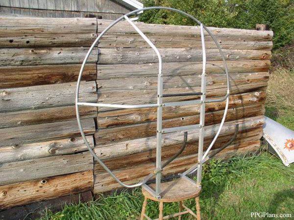
15 Picture 11 Stand the frame up and install the radial tubes and cage hoop, make sure everything looks straight and square. Look at it from the side and check that the hoop is straight. If it is a bit warped looking you may need to adjust the radial tube to hoop connectors by loosening them a bit and twisting that hoop section. Once you are satisfied you can drill the 7/32 holes through one wall of each of the tubes being connected to hold the hoop section joints in place above the radial tubes with the single button clips. Finally drill the ¼ inch hole all the way through for double button clips to connect the lower hoop sections to the bottom 21 inch chromoly tube. Picture 11 J Bars. For Paracruiser, Aerothrust, Blackhawk, Miniplane and Fantom harnesses Flatten the end of the J bar closest to the harness in a vise. Flatten this end 90 degrees to the small hole. It does not need to be closed tight, only about halfway closed. File all sharp edges nice and round, this flat end will slide into the pocket on the harness webbing, you want no sharp edges there. Picture 12


16 Picture 12 For locating the position of the hole, it is best to have your harness and slide the J bar into the pocket and mark your hole location. Drill 7/32 hole, use a flathead bolt through the grommet on the harness and through the J bar, with a nylock nut on the backside. Cut off and bolt protruding past the nut and file smooth. Picture 13 Picture 13

17 For Fly Products harnesses, a J bar with different dimensions is needed. A drawing for this J bar will be available in the future. Also needed are the plastic J bar ends available from for the webbing to slide through. Slide the long straight part of the J bars into the protruding ends of the diagonal braces all the way to the bolt. This can be a challenge as the J bar can be a tight fit in the square tube. File or grind a nice bevel on the end of the J bar, use a scotch-brite pad or steel wool to remove the coating on the chromoly, use some grease and just twist and turn until the J bar bottoms out on the bolt. It can be done! Drill a ¼ inch hole through the diagonal brace and J bar and install a double button clip or AN4-14A bolt. Picture 14 Picture 14 Engine Mounts. If using the Corsair M25Y or M19Y make the motor mounts as on the drawing. The radius to clear the starter can be cut with a jig saw with metal blade. The dimensions for attaching these engine mounts are on the drawings.


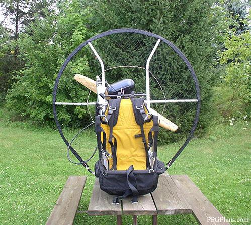
18 Fuel Tank Mounting. Use the 1 inch x 1/8 angle to mount the fuel tank of your choice. Recommended is the tank from it is tall and narrow providing the best prop clearance available. Shown below is an example of the paracruiser tank mounted in a V2 frame.

19 Finish. Round off all sharp edges, especially near the harness and where paraglider lines will meet the hoop. You may want to add foam padding around the tubes at the bottom of the frame such as the 90 degree corner in the square tubing in case of contact with your legs. Adding wheels at these corners will reduce the chance of the frame digging in on a not so good landing, as well as making the unit easy to roll around the garage. A couple of 4-6 inch off road skate board wheels make a good choice. More photos.
20
Skybolt V2. Construction Manual. Revised Version: January 2010
 Skybolt V2 Construction Manual Revised Version: January 2010 Index Skybolt V2 Construction Manual Page Warnings & Disclaimer 3 Acknowledgements 3 Tools Used 4 Tips 4 Layout 5 Frame - Center Section 6 Building
Continue gluing the remaining top parts ensuring the angled piece is glued well. Set aside and let dry. See photo below
 Radiator rev 1.1 The SE5a s radiator is one of the most recognized radiators in WW1. It is one of the components that defines the SE5a. The original SE5a has seen multiple radiator designs used during
Thank you for purchasing our product! *Please read these instructions and follow them step by step.*
 07/07/08.rev1 PAGE 1 OF 11 601AL VERTICAL 60120VL LIFT W/CHAIN DRIVE WINCH Thank you for purchasing our product! *Please read these instructions and follow them step by step.* Step 1. Separate and group
400A 40113V, 401A 40120V, & 401AL 40120VL ALUMINUM VERTICAL 4000 LB LIFT INCLUDES SCREW LEG ASSEMBLY INSTRUCTIONS
 12/11/07 PAGE 1 OF 12 400A 40113V, 401A 40120V, & 401AL 40120VL ALUMINUM VERTICAL 4000 LB LIFT INCLUDES SCREW LEG ASSEMBLY INSTRUCTIONS Thank you for purchasing our product! *Please read these instructions
Hinge Mortising Jig. One of the make it or break it parts of building a. 6 ShopNotes No. 74
 Hinge Mortising Jig A Mortise for a Hinge. Quick, clean, and accurate that s the only way to describe the mortise you get with a trim router and this hinge mortising jig. One of the make it or break it
CONSTRUCTION GUIDE 21ft Wide and 24ft Wide SHEEP HOUSE
 The Outside, Inside CONSTRUCTION GUIDE 21ft Wide and 24ft Wide SHEEP HOUSE Thank you for purchasing a Premier Sheep House. Please take the time to carefully read through this Construction Guide before
Low/High Tunnel Greenhouse Plans
 Low/High Tunnel Greenhouse Plans Tools Needed (See the complete list of Greenhouse Tools) Hacksaw or Reciprocating Saw Socket Wrench, Adjustable Wrench or Nut Drivers Electric Drill with Drill Bits Sledge
SE5a Instrument Board part 2 - rev 1.1
 SE5a Instrument Board part 2 - rev 1.1 Fuel (Petrol) Valve This valve uses two circular name plates, eight brass screws, one black plastic base, copper wire and two black plastic risers. You can pick any
6625 WEST WILSHIRE BLVD. OKLAHOMA CITY, OK (405) FAX (405)
 FAX (405)") INSTALLATION INSTRUCTIONS FOR BEDSIDE INNER REPAIR PANELS 67-72 GM FLEETSIDES This instruction illustrates the removal and replacement of the often rusted and damaged lower inner flanges on the 1967-1972
INSTALLATION INSTRUCTIONS FOR BEDSIDE INNER REPAIR PANELS 67-72 GM FLEETSIDES This instruction illustrates the removal and replacement of the often rusted and damaged lower inner flanges on the 1967-1972
Assembly Instructions 10 X 10 Aluminum Roof Support
 Assembly Instructions 10 X 10 Aluminum Roof Support Aluminum Roof Support Bolt Package 16-5/16 X 2 ¼ SS Bolt 24-5/16 X 1 SS Bolt 40-5/16 SS Nylon Lock Nuts 16-5/16 SS Flat Washers 28-4 ½ Wood Screws 36-1
Side "A" Stake here. Side "C" Side "D" Side "B" Here Shirley and I are setting up a 10 X 16 ground work.
 Choosing the Location It is always best to locate your greenhouse so that it can receive maximum sunlight at all times of the year especially in winter months. If Possible orient the long side towards
woodworkersjournal.com MATERIAL LIST
 MATERIAL LIST T x W x L 1 Legs (2) 1 1 2" x 3 1 2" x 36 7 16" 2 End Uprights (2) 1 1 2" x 3 1 2" x 32 1 2" 3 Stringers (4) 1 1 2" x 3 1 2" x 42" 4 Top Cladding, Long (2) 3/4" x 7 1 4" x 65 3 4" 5 Side
Work Space Set-up. Slats will level the pipe during bending and help minimize twisting of the bow.
 Work Space Set-up Affix pipe bender to end of working surface Slats will level the pipe during bending and help minimize twisting of the bow. Make the slat height equal the distance from your work surface
CONSTRUCTION GUIDE 27ft Wide and 30ft Wide SHEEP HOUSE
 The Outside, Inside CONSTRUCTION GUIDE 27ft Wide and 30ft Wide SHEEP HOUSE Thank you for purchasing a Premier Sheep House. Please take the time to carefully read through this Construction Guide before
Obtained from Omarshauntedtrail.com
 DaveintheGrave's Halloween Props Animated Crawling Skeleton Build a life-size skeleton torso that realistically crawls across the lawn one arm at a time. 1. Motor Base and Linkage Assembly BASE - I used
installation guide 1 GUIDE#: pwb-assault-001
 assault WAKEBOARD tower installation guide INSTALLATION SUPPORT 1 important information This Aerial wakeboard tower fits motor boats with 76-108 inch wide beam widths. This measurement is taken from the
Precision Steel Car s 100 T Steel Coil Car
 Precision Steel Car s 100 T Steel Coil Car Precision Steel Car www.precisionsteelcar.com info@precisionsteelcar.com Paul Vernon: (513) 571-5739 Revised 4/30/2009 Contents of Kit Main Tube Side Frame 2
User Instructions Multiline Otter Scoreboard Caddy Assembly
 List of parts: User Instructions Multiline Otter Scoreboard Caddy Assembly Single Caddy Double Caddy 1 1 Base assembly with attached wheels 2 4 1 1 2 4 4 8 10 20 12 Uprights (60 or 74 aluminum extrusion)
Q-Zone Hoop-Frame. Assembly Instructions. Copyright July 11, 2018 Grace Company (Reproduction Prohibited) Version 1.8
 Version 1.8") Q-Zone Hoop-Frame Assembly Instructions Copyright July 11, 2018 Grace Company (Reproduction Prohibited) Version 1.8 Table of Contents Table of Contents... i Warranty... ii Parts List Box 1...iii Box 2...
Q-Zone Hoop-Frame Assembly Instructions Copyright July 11, 2018 Grace Company (Reproduction Prohibited) Version 1.8 Table of Contents Table of Contents... i Warranty... ii Parts List Box 1...iii Box 2...
installation guide 1 GUIDE#: pwb-assault-004
 assault WAKEBOARD tower installation guide INSTALLATION SUPPORT 1 important information This Aerial wakeboard tower fits motor boats with 76-108 inch wide beam widths. This measurement is taken from the
Assembly Instructions 10 X 10 Aluminum Frame Building
 Assembly Instructions 10 X 10 Aluminum Frame Building 27 97 9 8 47 36 74 52 10 10 X 10 Square Building W/ Dome Includes: The Steel Entry Door with a Dead Bolt Lock assembly and Aluminum Door Frame. Metal
Side "C" Stake here. Side "B" Here Shirley and I are setting up a 10 X 16 ground work.
 Choosing the Location It is always best to locate your greenhouse so that it can receive maximum sunlight at all times of the year especially in winter months. If Possible orient the long side towards
END FRAMES. End frames built using pressure treated 2x4 (1 1/2" x 3 1/2") 36" 34" 7/16" pilot hole. 5 1/2" x 1/2" lag bolt 8" wheel 23"
 36 34 7/16 pilot hole. 5 1/2 x 1/2 lag bolt 8 wheel 23") END FRAMES End frames built using pressure treated 2x4 (1 1/2" x 3 1/2") 23" 17 1/2" (B) (B) Measure from the bottom of your stone to 1" below the lip to get your measurement. 17 1/2"(B) 36" 34" 1/2" flat
END FRAMES End frames built using pressure treated 2x4 (1 1/2" x 3 1/2") 23" 17 1/2" (B) (B) Measure from the bottom of your stone to 1" below the lip to get your measurement. 17 1/2"(B) 36" 34" 1/2" flat
The Compound Gothic Design
 The Compound Gothic Design You are building the Template Hoop, after it is completed all tubing can be precut and remaining hoops assembled on top of this template hoop, one at a time. Don t build and
OPERATIONS MANUAL. Port-O-Slitter
 Tapco Products Company The World Leader in Specialty Tools for the Professional Port-O-Slitter OPERATIONS MANUAL General instructions, set up, accessories and guide to using your portable precision slitting,
Sunrise Deck Assembly Instructions for Kingston Left
 Sunrise Deck Assembly Instructions for Kingston Left It s easiest to build the deck frame first like it will be lying on its back and then after all 4 legs and horizontals are in place, tip the deck toward
Install Instructions. NewAge Steel Welded Tall Locker
 Kit Contains Full Width Adjustable Steel Shelves (4) Height-Adjustable Steel Leveling Legs (4) Aluminum Door Trim (2) 2.5 x ¼ Cabinet Mounting Lag Bolts (4) Large Zinc Plated Mounting Washers (4) 5/8 x
PORTA-DOCK, INC. AP17 APD DS 4 X 16 T12 AW17 CPD DS 4 X 16 T12
 Page 1 of 7 PORTA-DOCK, INC. AP17 APD DS 4 X 16 T12 AW17 CPD DS 4 X 16 T12 *For Beige Decking Add the Letter B to Model* Thank you for purchasing out product! *Please read these instructions and follow
C70 Window Roller Repair Taken from: Heres the problem:
 C70 Window Roller Repair Taken from: http://www.volvospeed.com/vs_forum/topic/115086-how-to-c70-window-rollers-permanent-fix/ Heres the problem: This happened to two separate window assemblys on my c70
Depending on the size you ordered you will have either 5 Foot sections which will build the 10 Foot frame or 6 Foot sections which will build the 12
 XL Quilting Frame 1 Depending on the size you ordered you will have either 5 Foot sections which will build the 10 Foot frame or 6 Foot sections which will build the 12 Foot frame Printed 2 June 2014 Updated
PACKING LIST MACO V-5000
 PACKING LIST MACO V-5000 PART QTY O.D. SIZE LENGTH DESCRIPTION CHECKLIST T47P 4 5/8.050 36 Aluminum Tubing _ T43P 1 7/8.050 48 Aluminum Tubing _ T18P 1 3/4.050 48 Aluminum Tubing _ T15P 1 5/8.050 48 Aluminum
TOOL LIST FOR TAILGATE HIDDEN LATCH & LINK ASSY FOR FORD FLARESIDE TRUCKS
 TOOL LIST FOR TAILGATE HIDDEN LATCH & LINK ASSY FOR 53-87 FORD FLARESIDE TRUCKS Vise Grip Clamps C-clamps Sharpie Marker Ball Peen Hammer Center Punch 3/8 or 1/2 Drill 5/32, 7/32, 9/32, and 3/8 Drill Bits
Section 1 Safety working at height
 Contents Section 1 Safety working at height. Section 2 Hi-Step package contents & parts identification. Section 3 Assembly. Section 4 Operation. Section 5 Maintenance. Section 6 Extender package contents
Hatchback Wing Riser Kit
 Hatchback Wing Riser Kit 2015-06-11 Thank you for purchasing this PERRIN product for your car! Installation of this product should only be performed by persons experienced with installation of aftermarket
Dusty Harp Pickup for lever harps
 q P10 for 24 30 string harps q P20 for 32 40 string harps Dusty Harp Pickup for lever harps Installation Kit Contents and Diagram of Pickup A. Pickup Element B. Grommet C. Pickup Harness D. Jack E. F.
Building and installing dividing walls, by Tobias Sternberg
 Building and installing dividing walls, by Tobias Sternberg This instruction sets out to show one way to build and install simple dividing walls for studio spaces. I have written it as clearly as possible.
Tools and Tips: ( 1 )
") Tools and Tips: As you build instructions will show in my many picture manual how to assemble. You can use your own methods as you desire, my results are very good. A smooth, flat work surface is very
Tools and Tips: As you build instructions will show in my many picture manual how to assemble. You can use your own methods as you desire, my results are very good. A smooth, flat work surface is very
FIRST TEAM SPORTS, INC.
 FIRST TEAM SPORTS, INC. INVADER EZ-CRANK PORTABLE BASKETBALL GOAL ASSEMBLY INSTRUCTIONS Revised - 08/04/10 BILL OF MATERIALS (1) BASE TANK (1) BACKBOARD MOUNT (2) 5/16 X ¾ HEX BOLT (1) LOWER POST (2) SPRING
Agricultural Mechanics and Technology Power Tool Safety Rules
 Agricultural Mechanics and Technology Power Tool Safety Rules Name: BAND SAW Use: Cutting curves, circles and irregular shapes. 1. Use clean SHARP blades. 2. The teeth should always point DOWN. 3. Adjust
Large Wood Windmill Assembly Instructions
 CROW S NEST (TOP VIEW) TOWER (SIDE VIEW) 0 QTY 2 2 ITEM QTY 2 QTY QTY 8 QTY 8 QTY 4 TOP TOP TOP 47 9 QTY 4 QTY 4 QTY 4 QTY 4 QTY 4 ITEM 6 ITEM 7 ITEM 8 ITEM 3 ITEM 9 ITEM 4 ITEM 2 ITEM 5 47 Leg QTY 4 42.5
A WORD ABOUT BRACING PART A - BUILDING A STRAIGHT, PILE BENT, OPEN DECK TRESTLE. Built in Place, Straight
 BUILDING LARGE SCALE TRESTLES You have many options when building a large scale trestle. The choices you make may be based on the prototype you are modeling; the era or industry you are modeling; or, simply
Kwik-Lock. Installation Instructions. Attention Dealers: Please give this owners manual to the customer when the product is delivered.
 Serving the Truck & Trailer Industry Since 1944 Installation Instructions Attention Dealers: Please give this owners manual to the customer when the product is delivered. Call 800-535-9545 www.aeroindustries.com
Tools: Sharpie, Square, Vise, Hack saw, Ruler, Punch, Hammer, File. 2. Cut the stock Place stock in vise and cut with hack saw
 Purpose: MAKE CATAPULT ARM Step 1 Tools: Sharpie, Square, Vise, Hack saw, Ruler, Punch, Hammer, File Materials: Flat aluminum ½ inch stock (see picture below) Gloves required 1. Pick up the aluminum ½
10x10 Trellis Pergola
 0x0 Trellis Pergola ASSEMBLY GUIDE Ver.0-7 Table of Contents PAGE Introduction & Overview...................................................... Pergola Materials Overview..............................................................
GrowSpan Single Swinging Door Black-Out Door Kit
 GrowSpan Single Swinging Door Black-Out Door Kit ATTENTION: Door kit includes materials for door only. All other components shown in the diagram above and diagrams throughout this guide are not included
Tools and Tips: ( 1 )
") Tools and Tips: As you build instructions will show in my many picture manual how to assemble. You can use your own methods as you desire, my results are very good. A smooth, flat work surface is very
Tools and Tips: As you build instructions will show in my many picture manual how to assemble. You can use your own methods as you desire, my results are very good. A smooth, flat work surface is very
GroundControl. Follow instructions contained in this manual. Incorrect installation could result in serious injury or damage to property.
 GroundControl TM use supplied hardware Use only hardware supplied in your GroundControl kit or supplied by an authorized YAKIMA dealer. Use of unauthorized parts in the GroundControl system could result
Roll In W/L Dock PAGE 1
 Roll In W/L Dock PAGE 1 1 2 3/8 X 1 CARRIAGE BOLT SS 3/8 FLANGE NUT BRASS 3 4 1/2-13 X 1.25 SQ BOLT SS 1/2 SQ NUT BRASS 5 3/8-16 X 2.5" BOLT SS PAGE 2 6 7 BRACE BRKT SINGLE AXLE TUBE 8 9 3" AXLE WASHER
Installation Guidelines
 Page 1 Tools You ll Need 4 ft. Carpenter s level Chalk line (to mark U channel locations) Cordless drill/nut driver Caulking gun Chop saw with a metal cutting blade on it (required to make accurate and
WATSON RACING 4- & 6-POINT ROLL BAR Mustang Coupe p/n WR-BOLTINCAGE p/n WR-BOLTINCAGE6PT
 WATSON RACING 4- & 6-POINT ROLL BAR 2005-2014 Mustang Coupe p/n WR-BOLTINCAGE p/n WR-BOLTINCAGE6PT The Watson Racing 4-Point & 6-Point Roll Bars were designed for superior strength while allowing for installation
The Queen Quilter Professional Quilters Kit Frame
 The Queen Quilter Professional Quilters Kit Frame Assembly Instructions Table of Contents: Before you begin......................... Pg. 2 Wood parts............................. Pg. 3 Hardware..............................
ASSEMBLY AND CARE INSTRUCTIONS JUST FOR KIDS 355
 ASSEMBLY AND CARE INSTRUCTIONS VERSION: 8920100 (Revised 06/16) JUST FOR KIDS 355 SALES AND SERVICE spiethamerica.com Canada and International 135 Forestview Road, PO Box 40 Orillia, Ontario, Canada L3V
installation guide 1 GUIDE#: pwb-wwtowv1-pol-003
 g300 WAKEBOARD tower installation guide INSTALLATION SUPPORT 1 important information This WakeWorks wakeboard tower fits motor boats with 76-108 inch wide beam widths. This measurement is taken from the
136 PLYWOOD DESK 522
 136 PLYWOOD DESK 522 Simple in design and inexpensive, this plywood desk is made from a single 4- x 8-foot panel. Plywood is available with many hardwood veneers; it can also be covered with plastic laminate,
Playground Assembly Instructions
 Before You Begin Playground Assembly Instructions Locate the playground set on firm, level ground. Assemble the playground on or close to its permanent location Two people are recommended to assemble the
Installation Fence Guide Kodiak Iron. Exceptional Fencing Extraodinary Customer Service
 Installation Fence Guide Kodiak Iron Exceptional Fencing Extraodinary Customer Service Kodiak Fence System Installation Guide Thank you for the purchasing the Kodiak Fence System. Fence installation is
LANDING GEAR. 1. Fit landing gear into slots on bottom of fuselage.
 LANDING GEAR 1. Fit landing gear into slots on bottom of fuselage. 4. Use channel-lock pliers to press blind nuts into position (note: drilled hole should be slightly smaller than shaft of blind nut for
SMARTfit Functional and Brain Fitness Training Multi-Station Trainer Installation for Stud and Concrete Walls (US)
") SMARTfit Functional and Brain Fitness Training Multi-Station Trainer Installation for Stud and Concrete Walls (US) 2017 SMARTfit, Inc. www.smartfitinc.com 1 Unlike other fitness equipment which may require
SMARTfit Functional and Brain Fitness Training Multi-Station Trainer Installation for Stud and Concrete Walls (US) 2017 SMARTfit, Inc. www.smartfitinc.com 1 Unlike other fitness equipment which may require
Important Note. Tools Required: Welder capable of fully welding 10 GA.135 steel
 INSTALLATION INSTRUCTIONS Frame Reinforcement Kit 11100 (Patent Pending) 1968-72 GM A-Body Coupe/Sedan Read Instructions FULLY before starting Installation Important Note Installation of this kit requires
GlideRite Retractable Cover System For HotSpring & Tiger River Spas (except Classic & pre-2000 Landmark Spas)
") List of Contents Quantity Description 12 #10 x 1 ½ Flat Head Phillips Screw (see pg. 2) 2 #10 x ½ Pan Head Phillips Screw (see pg. 2) 8 ¼ x 2 ½ Lag Bolt (see pg. 2) 7 ¼ 20 x 5 / 8 Hex Head Bolt (see pg.
List of Contents Quantity Description 12 #10 x 1 ½ Flat Head Phillips Screw (see pg. 2) 2 #10 x ½ Pan Head Phillips Screw (see pg. 2) 8 ¼ x 2 ½ Lag Bolt (see pg. 2) 7 ¼ 20 x 5 / 8 Hex Head Bolt (see pg.
Technicians of Terror. This is the air valve we make to use with our air
 These are pictures of our scissor prop. Technicians of Terror http://www.halloweenfear.com/scissorprop.html props. This is the air valve we make to use with our air This pictures the duel door closer cylinders
Electrical Construction Name:
 Tools of the Trade The following are common tools that are used in the electrical industry. This hand-out is to help familiarize you with the tools, the terminology, and their use. Retractable Steel tape
200A FLB VERTICAL 22113V LIFT W/CHAIN DRIVE WINCH
 PG. 1 OF 11 PORTA-DOCK, INC. 200A FLB VERTICAL 22113V LIFT W/CHAIN DRIVE WINCH STEP 1. Separate and group like parts and fasteners together. Locate the winch side member with the longer upright tube and
Twin-Wall Double Swinging Door Kit
 115021 Twin-Wall Double Swinging Kit READ THIS DOCUMENT BEFORE YOU BEGIN Thank you for purchasing this GrowSpan door kit. When properly assembled and maintained, this product will provide years of reliable
6' Wide Premium Greenhouse Benches
 6' Wide Premium Greenhouse Benches Premium Greenhouse Bench with Stationary Top 2015 FarmTek All Rights Reserved. Reproduction is prohibited without permission. STK# DIMENSIONS 112416S6X08 6' W x 3' H
# in 1 Metal Worker Auxiliary Operating Instructions
 340 Snyder Avenue, Berkeley Heights, NJ 07922 www.micromark.com MMTechService@micromark.com Tech Support: 908-464-1094, weekdays, 1pm to 5 pm ET #86556 3 in 1 Metal Worker Auxiliary Operating Instructions
Mount to the Wall INSTALLATION MANUAL
 Mount to the Wall 15 Locate the Wooden Studs This step applies to wooden stud wall installation only. Determine and mark the exact locations of two stud centers on the wall. Wooden studs should be spaced
ClearSpan PolyMax Windbreak Wall
 ClearSpan PolyMax Windbreak Wall Photo may show a different but similar model. 2007 ClearSpan All Rights Reserved. Reproduction is prohibited without permission. Revision date: February 2007ldg STK# DIMENSIONS
FORWARD FUSELAGE SIDES & REAR TOP SKINS
 FORWARD FUSELAGE SIDES & REAR TOP SKINS WORK REPORT Step No. Check Parts / Tools Qty Preparations. 1 [ ] 6F5-3 Upper Front Longerons 2 2 [ ] 6F5-5 Heel Support 1 3 [ ] 6F5-2 Front Floor Skin 1 3 [ ] Firewall
THANK YOU FOR PURCHASING FROM HERITAGE PATIOS
 Installation Guide THANK YOU FOR PURCHASING FROM HERITAGE PATIOS Your purchase is engineered by nearly a half century of commercial and residential product design proudly manufactured in the USA from responsibly
Jeep Wrangler JK & 4-Door Front Pair Part # Revision H
 Jeep Wrangler JK 2007 2 & 4-Door Front Pair Part # 10045 Revision H 03-25-09 Step 1: Prior to Installation: A) Bushwacker only approves installing the flares according to these written instructions with
Mach Wall Installation Instructions
 Mach Wall Installation Instructions Planning the Job Since Mach Wall is an innovative product that accomplishes 3 tasks at the same time (frame, insulate and drywall) and it replaces traditional framing,
1949 to 1954 Chevrolet Dual Master Cylinder Conversion
 1949 to 1954 Chevrolet Dual Master Cylinder Conversion This document is a one stop shop to getting your brake system updated on your old Chevy. Whether you re going with a disc conversion or just sticking
PTC Model 4. Programmable Turntable Controller. Basic Motor Mount Kit P/N Installation Instructions
 PTC Model 4 Programmable Turntable Controller M Basic Motor Mount Kit P/N 09-820 Installation Instructions New York Railway Supply 625 Aviator Dr Fort Worth TX 76179 (817) 233-5068 http://www.nyrs.com
Sales & Service. JFK - Just For Kids. sasportonline.com. 135 Forestview Road 7879 Will Rogers Blvd.
 Sales & Service sasportonline.com SA Sport (Canada) SA Sport (U.S.A.) 135 Forestview Road 7879 Will Rogers Blvd. P.O. Box 40 Fort Worth, Texas Orillia, Ontario USA 76140 Canada L3V 6H9 Telephone: (705)
MONKEY BARS OVERHEAD RACK INSTALLATION
 MONKEY BARS OVERHEAD RACK INSTALLATION Thank you for purchasing the New Monkey Bars Overhead storage rack. The most innovative overhead rack on the market WARNING THE PROPER INSTALLATION OF THIS STORAGE
CONTENTS TOOL LIST U P S I D E I N N O V A T I O N S, L L C RAMP AND STEP SYSTEM ASSEMBLY INSTRUCTIONS. Revised: June 2013
 U P S I D E I N N O V A T I O N S, L L C RAMP AND STEP SYSTEM ASSEMBLY INSTRUCTIONS TOOL LIST Required Tools: - Reciprocating Saw with Metal Cutting Blade - Drill - 7/16 Drill Bit for Metal Drilling -
MantelMount. TM1A Installation Instructions IMPORTANT SAFETY INSTRUCTIONS - SAVE THESE INSTRUCTIONS
 MantelMount TMA Installation Instructions IMPORTANT SAFETY INSTRUCTIONS - SAVE THESE INSTRUCTIONS TM Thank you for choosing the MantelMount television wall mount. Please read this entire manual before
Frameless Inline Door With Return QCI5263
 INSTALLATION INSTRUCTIONS Frameless Inline Door With Return QCI5263 WALL MOUNT HINGES FRAMELESS DOOR / PANEL / RETURN PANEL QCI5263 REV. 0 Page 1 Certified 06/17/2016 Parts List with wall mount hinges
GlideRite Retractable Cover System For Hot Spot Spas (SE & SLX only)
") List of Contents Quantity Description 12 #10 x 1 ½ Flat Head Phillips Screw (see pg. 2) 2 #10 x ½ Pan Head Phillips Screw (see pg. 2) 8 ¼ x 2 ½ Lag Bolt (see pg. 2) 7 ¼ 20 x 5 / 8 Hex Head Bolt (see pg.
List of Contents Quantity Description 12 #10 x 1 ½ Flat Head Phillips Screw (see pg. 2) 2 #10 x ½ Pan Head Phillips Screw (see pg. 2) 8 ¼ x 2 ½ Lag Bolt (see pg. 2) 7 ¼ 20 x 5 / 8 Hex Head Bolt (see pg.
RLP Flat Track Hardware sliding door hardware/ barn door track
 Page 1 of 9 Installation Suggestions for: RLP Flat Track Hardware sliding door hardware/ barn door track Read these instructions to end before starting installation or ordering hardware. Reclaimed Lumber
SMARTfit High Intensity Cognitive Training. SMARTfit Trainer Installation Manual for Stud and Concrete Walls Revision 1.3
 SMARTfit High Intensity Cognitive Training SMARTfit Trainer Installation Manual for Stud and Concrete Walls Revision 1.3 2015 Unlike other fitness equipment which may require additional insurance, SMARTfit
ClearSpan PolyMax Windbreak Wall
 ClearSpan PolyMax Windbreak Wall Photo may show a different but similar model. 2007 ClearSpan All Rights Reserved. Reproduction is prohibited without permission. Revision date: April 2007ldg STK# DIMENSIONS
Spiral Slide
 IMPORTANT Page 1 PLEASE READ THESE INSTRUCTIONS BEFORE COMMENCING ASSEMBLY. All equipment must be installed in accordance with these instructions. Check your shipment against Bill of Lading and Parts list.
installation guide 1 GUIDE#: PWB-wwpontoon-pol-004
 f250 pontoon WAKEBOARD tower installation guide INSTALLATION SUPPORT 1 important information This WakeWorks tower fits Pontoon boats with 96 to 102 inch wide beam widths. This measurement is taken from
Why are we giving this guidebook as a FREE download?
 Construction Guide Queen, Double & Twin Vertical 1 Note: This guide covers the construction steps for all 3 sizes of the vertical wall mount Easy DIY Murphy beds, Queen, Double and Twin. The construction
CHEVY/GMC SuperRail Mounting Kit #3117
 CHEVY/GMC SuperRail Mounting Kit #3117 #3100 SuperGlide (12K) Gross Trailer Weight (Maximum) Vertical Load Weight (Max. Pin Weight) 12,000 lbs. 3,000 lbs. Installation Instructions SPECIFICATIONS Fits
INSTRUCTION BOOKLET #34. For Wallbed models: KING SIZE SIERRA WITH STORAGE HEADBOARD
 For Wallbed models: KING SIZE SIERRA WITH STORAGE HEADBOARD INSTRUCTION BOOKLET #34 WARNING! ALL MURPHY/WALLBED SYSTEMS CONTAIN STORED ENERGY. FAILURE TO USE AND FOLLOW THESE INSTRUCTIONS DURING THE INSTALLATION
Thank you for purchasing out product! *Please read these instructions and follow them step by step. *
 Page 1 of 7 AD17 AA DS 4 X 16 T12 Thank you for purchasing out product! *Please read these instructions and follow them step by step. * STEP 1. Slide two support posts (REF. # 24) into the two outside
Please read BOTH these Installation Instructions and the General Towing Instructions before attempting to install or operate this equipment.
 2005-08 Pontiac G6 GT Please read BOTH these and the General Towing Instructions before attempting to install or operate this equipment. 1. Blue Ox towing products and accessories are intended to be installed
INSTALLATION INSTRUCTIONS FOR FRONT CASTING DECK RAIL Ranger
 INSTALLATION INSTRUCTIONS FOR FRONT CASTING DECK RAIL Ranger TOOLS REQUIRED FOR INSTALLATION: Drill motor, (1) 5/16 inch drill bit, (1) 13/64 drill bit, (1) 3/16 inch hex wrench (1) 3/32 inch hex wrench.
FINISH CARPENTRY. Installing Arched Casing How to make three different arched trim details look like they grew there
 FINISH CARPENTRY 1 2 3 Installing Arched Casing How to make three different arched trim details look like they grew there Photos by Gary Striegler BY GARY STRIEGLER I love the challenge of trimming arched
Installation Guidelines
 Page 1 Tools You ll Need 4 ft. Carpenter s level Chalk line (to mark U channel locations) Cordless drill/nut driver Caulking gun Chop saw with a metal cutting blade on it (required to make accurate and
OPERATIONS MANUAL. Port-O-Slitter
 OPERATIONS MANUAL Port-O-Slitter General instructions, set up, accessories and guide to using your portable precision slitting, rib forming and perforating system Saves hours on large siding jobs! Featuring:
7 X 10 X 6 SHELTER 7 X 16 X 6 SHELTER 12 X 10 X 6 SHELTER 12 X 16 X 6 SHELTER
 ASSEMBLY INSTRUCTIONS FOR 7 X 10 X 6 AND 7 X 16 X 6 ATV SPORT SHELTER ACTUAL FRAME SIZES: 7 X 9-1 1/2 X 6 AND 7 X 13-7 1/2 X 6 AND 12 X 10 X 6 AND 12 X 16 X 6 ATV SPORT SHELTER ACTUAL FRAME SIZES: 12 X
Installation Instructions For Slider Casement Air Conditioners
 Installation Instructions For Slider Casement Air Conditioners NOTE: These instructions describe installation in a typical wood framed window with a wood SLIDE-BY sash, or installation in a metal CASEMENT
Oceanside Outdoor Vinyl Shower Kit (3 x 3 Enclosure)
") Oceanside Outdoor Vinyl Shower Kit ( x Enclosure) A B ASSEMBLY GUIDE REQUIRED FOR INSTALLATION (A) Zippity Post Extension for In-Ground Installation (Sold as 4-Packs) (B) Zippity Galvanized Steel Surface
Oceanside Outdoor Vinyl Shower Kit ( x Enclosure) A B ASSEMBLY GUIDE REQUIRED FOR INSTALLATION (A) Zippity Post Extension for In-Ground Installation (Sold as 4-Packs) (B) Zippity Galvanized Steel Surface
General Wood Shop Notes
 General Wood Shop Notes Restricted Materials No METAL or BONE of any kind on any machine or in the room o See additional restrictions individual machine All reclaimed and other than new lumber must be
MM540 Installation Instructions IMPORTANT SAFETY INSTRUCTIONS - SAVE THESE INSTRUCTIONS
 MM50 Installation Instructions IMPORTANT SAFETY INSTRUCTIONS - SAVE THESE INSTRUCTIONS Please read this entire manual before you begin. Do not unpack any contents until you verify all requirements on PAGE.
10x10 Trellis Pergola
 0x0 Trellis Pergola ASSEMBLY GUIDE Ver.-007 Table of Contents PAGE 0x0 Trellis Pergola Introduction & Overview...................................................... Pergola Materials Overview..............................................................