Installation Instructions For Vinyl Sliding Patio Door & French Sliding Patio Door 1-Wide, 2-Wide and 4-Wide
|
|
|
- Clifford Carr
- 6 years ago
- Views:
Transcription

1 Installation Instructions For Vinyl Sliding Patio Door & French Sliding Patio Door 1-Wide, 2-Wide and 4-Wide Includes Instructions For Door and Frame Reversal For 2-Wide Doors and Jamb Extension Option Installation [Includes Instructions to Maintain Design Pressure Test Ratings] Installer Please leave this booklet for the homeowner after the install is completed. IMPORTANT: Please read before you begin. WS Part Rev. 6 5/08 Install A Rev. 6 5/08 Printed in U.S.A. 2008
2 Table of Contents and Tool/Material Requirements START PAGE Safety Alert Symbol; Definition DPR and non-dpr iii Preserving Design Pressure Test Ratings iv Design Pressure Rating Fastening Method (chart) v Design Pressure Rating Nailing Fin Configuration v Door Operation And Arrangement vi Rough Opening Preparation All Units Measuring Tape, Level Additional RO Checks for 4-Wide Door Long Level, Measuring Tape, Framing Square Straighten and Level Subfloor All Units Level, Hammer, Nails, Nail Set, Plane RO Preparation For DPR Installation All Units Utility Knife, Cloth Tape RO Preparation (cont.) Non-DPR Installation All Units Utility Knife, Cloth Tape, Staples, Staple Gun Sill Preparation All Units Weather Barrier Self-Adhering Tape, Utility Knife, Measuring Tape, Rubber Roller, Rough Opening Caulking Details All Installations Clear Silicone Sealant, Caulking Gun, Utility Knife Door Installation All Units Measuring Tape, Hammer, #8 Steel Screws (long enough to penetrate framing material at least 1-1/2"), Electric Drill w/screwdriver Bit, Pry Bar, Shims, Straightedge, Level NOTE: If maintaining design pressure ratings are not a concern, roofing nails long enough to penetrate framing material by at least 1-1/2" may be used instead of screws. Square and Straighten the Interior Measuring Tape, Shims, Level, Fiberglass Insulation, Hammer, Pry Bar Seal Head Weep Holes Clear Silicone Sealant, Caulking Gun Weather Barrier Tape Application DP Installations Utility Knife, Scissors, Cloth Tape, Clear Silicone Sealant, Caulking Gun Weather Barrier Tape Application Non-DP Installations Weather Barrier Self-Adhering Tape, Utility Knife, Measuring Tape, Rubber Roller Removing Screen; Installing Screen Guides; Installing Screen Phillips Head Screwdriver Screen Adjustment; Installing Screen Keeper 2-Wide Door Only Measuring Tape, Pencil, Phillips Head Screwdriver Remove & Install Sliding Panel; Adjust Sliding Panel 2-Wide Door Stiff-Bladed Putty Knife, Phillips Head Screwdriver Install Sliding Panels 4-Wide Door Stiff-Bladed Putty Knife, Phillips Head Screwdriver Panel Adjustments All Installations Stiff-Bladed Putty Knife, Phillips Head Screwdriver Shoot Bolt Adjustment 4-Wide Door Phillips Head Screwdriver Handle Installation 2-Wide Door Phillips Head Screwdriver Install Lock Keeper 2-Wide Door Phillips Head Screwdriver, Measuring Tape, #2 Pencil or Carpenter Pencil Handle Installation 4-Wide Door Phillips Head Screwdriver Reversing Door Frame 2-Wide Door Only Stiff-Bladed Putty Knife, Phillips Head Screwdriver, Needle Nose Pliers, Pry Bar Reversing Sliding Panel Stiff-Bladed Putty Knife, Phillips Head Screwdriver, Rubber Mallet, Wooden Block ii
3 Table of Contents and Tool/Material Requirements (cont.) START PAGE Reversing Door Lock Phillips Head Screwdriver, Slotted Screwdriver Install Lock Keeper 2-Wide Door Phillips Head Screwdriver, Small Flat Screwdriver OPTION INSTALLATIONS Jamb Extension - Measuring Tape, Hacksaw, Utility Knife, Rubber Mallet, Electric Drill with Drill & Screwdriver Bits, #7 x 1-1/4" Stainless Steel Flathead Screws, Combination Square Field Stacking Adding Transom 2-Wide Only Utility Knife, Measuring Tape, Tin Snips, Locking Pliers, Clear Silicone Sealant, Caulking Gun, Hacksaw, Level, Drill With Drill Bits and Screwdriver Attachment, Metal Brackets, Screws, Shop Towels, Denatured Alcohol Mull Strips - Configuration, Measuring & Cutting, Installation 2-Wide Only Measuring Tape, Hacksaw, Utility Knife, Tin Snips, Clear Silicone Sealant, Caulk Gun, Rubber Mallet, Shop Towels, Denatured Alcohol, Universal Mull Strips Turn Units Over 2-Wide Only Recommended Finishing Instructions Products With Synthetic Stucco Recognize this symbol. This is the Safety-Alert symbol. When you see this symbol be alert to the potential for personal injury or product damage. Falling from window or door opening may result in serious injury or death. DO NOT leave openings unattended when children are present. Weight of window and door unit(s) and accessories will vary. Use a reasonable number of people with sufficient strength to lift, carry and install window or door unit(s) and accessories. Always consider site conditions and use appropriate techniques when installing. CUT HAZARD *May cause serious injuries if broken. Screen will not stop children, any one or anything from falling out window or door. Keep children and objects away from open windows or doors. Definition: Throughout these instructions DPR equals For Design Pressure Rating. Any procedure so titled must be completed to maintain the rating validity. Non-DPR is for installations not requiring maintenance of design pressure ratings. In this case you can follow procedures for either DPR or non-dpr. iii
4 Preserving Design Pressure Test Ratings IMPORTANT: Thoroughly read and follow these instructions. Failure to install as recommended will void any warranty, expressed or implied. Before installation, check building codes for the area in which the doors are being installed, to ensure proper compliance. The installation instructions that follow are based on typical frame construction. Specific applications may differ. The door manufacturer recommends that you consult a qualified installation professional. The door manufacturer is not responsible for installation. IMPORTANT: A number of jurisdictions have adopted building code Design Pressure Requirements (DPR) that require window and door products be installed in the same way they were installed for laboratory testing. To comply with these requirements, we are pleased to supplement the installation instructions with the following: Sealant must be applied in all installations. Additionally, to maintain design pressure ratings, there must be continuous contact with a generous bead of sealant between the bare sheathing and the door unit s nailing fin around the door s entire perimeter. The following additional steps must be taken as appropriate to maintain design pressure ratings. Exterior weather resistant barrier (WRB) must be cut and temporarily taped back away from rough openings. When sealant is applied to the rough opening it must be applied directly to the building s sheathing and NOT the weather resistant barrier. The nailing fin or brickmould must contact the sealant continuously along the entire perimeter of the unit and must fully contact exterior face of the wall around the door s entire perimeter. Exterior weather resistant barrier must be trimmed and reapplied over the nailing fin. It must be sealed to the fin along the entire perimeter with silicone sealant. A shim space is required around the sides and head of the door to allow for structure movement, seasonal expansion and contraction, and to provide space for insulation. The shim space for DPR installations cannot exceed 1/4" on all sides (1/2" total for either width or height). For Non-DPR installation, the shim space may be 1/4" to 3/8" (1/2" to 3/4" total for either width or height). Accessories, such as jamb extension, may alter unit width and height. Check rough opening size vs unit size accordingly. If a shim space greater than listed above exists on the interior or exterior of the unit, use solid continuous furring material to fill this space until the maximum shim allowance is achieved. Doors do not require a shim space at the sill. Furring material must be solid, continuous, and run the full height and/or width of the rough opening. Furring strip depth must be at least equal to the door s jamb depth. Furring material must be securely fastened to the rough opening framing. Fastening methods must conform to those used to install test units. See the following page for correct fastener type, application spacing, and additional silicone sealant requirements. ADDITIONAL NOTES FOR ALL INSTALLATIONS: For any installation that has exposed fasteners, it is recommended to use fasteners made of 300 series stainless steel. Follow your local codes if they specify a different series of stainless steel. Certain options, accessories, and warranty considerations require the unit be installed using installation clips. The clip install method has not been tested for design pressure ratings and should not be used where design pressure ratings must be maintained. Contact your customer service representative for additional assistance. iv
5 Design Pressure Rating Fastening Method Vinyl Doors With Pre-Punched Fastener Holes Unit Description Fastener How to Fasten Nailing Fin with Pre-Punched Fastener Holes / No Brick - mould See FIGURE 1 below. #8 Steel screws long enough to penetrate framing material by at least 1-1/2". Start a screw 4" in from corner and apply through nailing fin into framing member. Space additional screws every 4" on center, around entire perimeter, staying 4" from each corner. Design Pressure Rating Nailing Fin Configuration VINYL DOORS HEAD PRE-PUNCHED FASTENER HOLE IN NAILING FIN A Special Note About Masonry SPACE FOR SEALANT WEATHER BARRIER TAPE SPACE FOR SEALANT SIDE VIEW WITH NAILING FIN / NO BRICKMOULD FIGURE 1 WEATHER BARRIER TAPE The perimeter joint between door exterior and the exterior building material must conform to siding manufacturers recommendations. All masonry, stucco, or synthetic stucco systems require an expansion joint around the door perimeter that must be filled with sealant compatible with the building material and door components. Expansion joint space should be no less than 3/8" and not greater than 1/2" unless stated otherwise by your siding manufacturer. If there is a conflict, follow siding manufacturer s guidelines. Failure of this joint will cause structural damage unrelated to door performance. The door manufacturer reserves the right, as necessary, to change product specifications, installation procedures, materials, prices and terms of purchase without notice. v
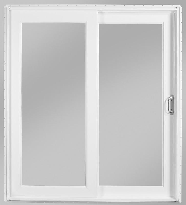
6 Door Operation and Arrangement Door Operation Patio door operation is viewed from the exterior of the unit (FIGURE 1). At time of order you can specify either a right or left active panel on a 2-wide unit. A right active panel is shown in (FIGURE 1). NOTE: If desired, 2-Wide, 6-8 doors ONLY can be reversed prior to installation so the opposite (left or right) panel becomes active. To do a reversal, the door frame, fixed panel, active panel and hardware must be reversed before installing unit in the rough opening. Reversal instructions start on Page 30. Only 2-Wide 6-8 doors are reversible. 4-Wide doors and taller 2-Wide doors are not reversible. Doors with the Blinds-In-Air-Space option are not reversible. The blinds would not function if the panel is rotated 180 degrees. DOOR ARRANGEMENT INTERIOR 2-Wide Door ACTIVE PANEL FIXED PANEL STANDARD 2-WIDE DOOR OPERATION (Viewed From Exterior) FIXED PANEL FIGURE 1 SLIDING (ACTIVE) PANEL On 4-Wide units, the Inactive Panel can be opened when the shoot bolts holding it shut are released. 4-Wide Door ACTIVE PANEL INACTIVE PANEL SCREENS FIXED PANEL FIXED PANEL The 2-Wide patio door ships with both panels installed in the frame. It is ready for installation once packing material is removed. The 4-Wide unit ships with the two fixed panels permanently mounted in the frame. The sliding active panel, inactive panel and screens are packaged separately from the frame. They are to be installed in the door unit after the frame and fixed panel assembly is installed into the rough opening. Rough opening (RO) preparation and installation is almost the same for 2-Wide or 4-Wide units. Unless specifically noted, the instructions should be followed for either a 2-Wide or 4-Wide unit. The 2-Wide and 4-Wide door units must be handled upright. Do not carry with panels parallel to the ground. vi


7 IMPORTANT: When accessories such as jamb extension have been ordered, apply according to the directions starting on page 37 BEFORE you install the unit OR prep the rough opening. Rough Opening Preparation All Units Wear gloves, safety glasses, goggles or eye-shields as appropriate. Read installation instructions completely before beginning procedure. FIGURE 1 FIGURE 2 FIGURE 3 ROUGH OPENING HEIGHT JAMB HEIGHT 1B JAMB WIDTH ROUGH OPENING WIDTH 2A 3A 1A IMPORTANT: To ensure the door panels operate smoothly, make sure the sill is level and straight and the opening is square. IMPORTANT: Perform the following BEFORE starting installation. Make sure you have: The correct door type (French, sliding, hinged, etc.) The correct size door (Width and Height) for your rough opening (FIGURE 1). Perform a complete unit inspection checking for shipping damage, broken glass, or other physical damage. Fix whatever is wrong before installation or start appropriate claim procedures. When accessories such as jamb extension have been ordered, apply according to the directions BEFORE you install the unit OR prep the rough opening. IMPORTANT: If unit is to meet design pressure ratings, a maximum 1/4" shim space is required around the perimeter. A shim space greater than 1/4" could result in lower product performance and may be considered non-compliant with certain building codes. NOTE: Doors do not require 1/4" shim space at the sill. Non-DPR installation shim space may be 1/4" to 3/8" (1/2" to 3/4" total for either width or height. If a shim space greater than listed, exists on the interior or exterior, use solid continuous furring material to fill this space until the maximum shim allowance is achieved. Furring material must be solid, continuous, and run the full height and/or width of the rough opening. Furring material depth must be at least equal to door jamb depth. Furring material must be securely fastened to the rough opening framing. 1. Measure the rough opening to ensure it meets the guidelines listed above. Check the rough opening dimensions against the unit s actual Jamb Height and Jamb Width (FIGURES 1A, & 1B). 2. Measure the opening diagonally from corner-tocorner (FIGURES 2 & 2A). The measurements should not differ more than 1/4". 3. Using a long level, check side and sill for plumb and level (FIGURES 3 & 3A). Make necessary corrections to ensure walls are plumb, straight and not twisted. 1
8 Additional RO Checks for 4-Wide Door FIGURE 1 FIGURE 2 CHECK SQUARE AT ALL CORNERS HEIGHT MUST REMAIN CONSTANT ALONG ENTIRE LENGTH TO ENSURE SMOOTH PANEL OPERATION. CHECK LEVEL AT SILL AND HEAD Because of the longer distances spanned with a 4-Wide door, it is critical that the rough opening be as perfectly level, plumb and square as possible. Check as shown in (FIGURES 1 & 2). Fix any problems before proceeding! Misalignment problems with the rough opening could be transferred to the 4-Wide door unit causing adjustment and operation difficulties for the active panels and screens. The 2-Wide and 4-Wide door units must be handled upright. Do not carry with panels parallel to the ground. 2
.")

. FIGURE 3 3. Check for level as in (FIGURE 1).")
9 Straighten & Level Subfloor All Units FIGURE 1 1. Masonry installation requires a 2 x 6 sill plate to be present. Check sill for level (FIGURE 1). Improper use of hand and power tools could result in personal injury and/or product damage. Follow equipment manufacturers instructions for safe operation. Always wear safety glasses. FIGURE 2 2. To straighten and level the subfloor, identify the areas that are above level and countersink nails in the floor area that will be under the door (FIGURE 2). FIGURE 3 3. Check for level as in (FIGURE 1). Plane area that will be under the door until it is straight and level (FIGURE 3). 3
10 RO Preparation For DPR Installation All Units FIGURE 1 WEATHER RESISTANT BARRIER CUT LINE ROUGH OPENING PERIMETER (DO NOT CUT!) The following instructions are for structures with weather resistant barrier (WRB) applied before the door is installed. Page 4 instructions must be followed if you are required to maintain design pressure ratings. If maintaining design pressure ratings are not a concern, skip to Page 5 for weather resistant barrier preparation. 1. Cut weather resistant barrier (WRB) as shown in (FIGURE 1). Cut sill straight across and parallel with the sill framing. 2. Fold WRB back and tape out of the way (FIGURE 2). Bare sheathing must be exposed. Turn to Page 6. FIGURE 2 WEATHER RESISTANT BARRIER CUT & TAPED BACK TO EXPOSE SHEATHING 45 9" SHEATHING BARE FRAMING 4
11 RO Preparation (cont.) Non-DPR Installation All Units The following instructions are for structures with weather resistant barrier (WRB) applied before doors are installed. FIGURE 1 FIGURE 3 WEATHER RESISTANT BARRIER CUT LINE Page 5 must be followed if you are installing units that do not need to maintain design pressure rating certification. FOLD WEATHER RESISTANT BARRIER INTO ROUGH OPENING FIGURE 2 ROUGH OPENING PERIMETER (DO NOT CUT!) 1. Cut weather resistant barrier (WRB) as shown in (FIGURES 1 & 2). Cut sill and head even with and parallel to framing. Cut diagonals in head WRB (FIGURE 2). 2. Lift head WRB up and tape to face of exterior (FIGURE 2). Fold side jamb WRB into the rough opening (FIGURE 3). 3. Secure WRB to interior framing with staples placed every 12" to 16" apart (FIGURE 4). If desired, trim excess before stapling. SEE DETAIL FIGURE 4 VIEWED FROM INTERIOR 9" 9" 45 FOLD WEATHER RESISTANT BARRIER TO INTERIOR. TRIM OFF EXCESS. STAPLE ENDS TO FRAMING. PLACE STAPLES EVERY 12" TO 16". 5
")
.")
12 Sill Preparation All Units FIGURE 1 FIGURE 2 WRB FOLDED INTO ROUGH OPENING 1. Cut a piece of weather barrier self-adhering tape 4" wide and as long as the opening width plus 8" (FIGURE 1). Apply to face of exterior wall so 1" extends above the opening and 4" extends beyond each side of the opening. Cut along the corners of rough opening and fold down onto the sill (FIGURE 2). 2. Apply a second continuous piece of weather barrier self-adhering tape on the top surface of the rough opening sill. Cut tape the thickness of the wall and 12" longer than the width of the opening. Align flush with interior of the wall (FIGURE 3). Start the piece (approximately 6") up the side of the rough opening and run it to the bottom of the opening, to the other side of the opening, and 6" up the other side (FIGURE 4). Use a rubber roller to apply barrier to surface (FIGURE 3). 9" 1" 4" FIGURE 3 FIGURE 4 6" 6

13 Rough Opening Caulking Details All Installations FIGURE 1 NON-DP INSTALL SHEATHING NOTE: If you have a 2-Wide door and want to change door operation, so the opposite panel opens, and the second panel is made stationary, do not install in rough opening yet. See pages 30 thru 35 to reverse door operation. Only 2-Wide, 6-8 doors are reversible! SILICONE SEALANT ON WRB SILICONE SEALANT APPLIED TO WEATHER BARRIER SELF-ADHERING TAPE ON SILL IMPORTANT: High-quality, exterior, neutral-cure, clear, silicone sealant (compatible with vinyl extrusion and exterior face of the wall) is to be used for all procedures in the following instructions which call for caulking or sealant. FIGURE 2 DP INSTALL IMPORTANT: Prior to applying sealant, ensure rough opening is square, level, and plumb. Perform any adjustments before applying sealant. Both Non-DP and DP installations require caulking on the sill and on the face of the rough opening (FIGURES 1 & 2). For Non-DP installations with WRB already applied, put sealant on top of WRB. DP installations must have sealant applied directly to the sheathing. Proceed as follows: 1. Apply a continuous, generous bead of silicone sealant along the head and vertical sides of rough opening perimeter. Locate sealant so it does not intrude into the rough opening and will also provide a continuous seal between sheathing and nailing fin or brickmould as well as door sill (FIGURES 1 & 2). 2. Apply continuous, generous silicone beads on the sill as shown in (FIGURE 3). Proceed to Door Installation on next page. FIGURE 3 SHEATHING SILICONE SEALANT APPLIED TO SHEATHING SILICONE SEALANT APPLIED TO WEATHER BARRIER SELF-ADHERING TAPE ON SILL SEALANT ON SUBFLOOR 1/2" CAULK BEAD ON EXTERIOR OF ROUGH OPENING 1-3/4" 7


14 Door Installation All Units FIGURE 1 FIGURE 2 SILL JAMB SHIM FIGURE 3 FLAT BAR Panels are heavy. Use caution when handling to avoid injury or damage. Use adequate number of people to safely handle panel. The 2-Wide and 4-Wide door assembly must be handled upright. Do not carry with panels parallel to the ground. IMPORTANT: After door is moved near the rough opening, remove the wood and cardboard used for shipping. DO NOT remove the plastic shipping blocks or open the door. IMPORTANT: If unit is to meet design pressure ratings, a maximum 1/4" shim space is required around the perimeter. Unit must be secured with #8 steel screws, long enough to penetrate framing material by at least 1-1/2". See Design Pressure Rating Fastening Method chart on Page v for screw spacing. NOTE: Doors do not require 1/4" shim space at the sill. NOTE: If maintaining design pressure ratings are not a concern, roofing nails long enough to penetrate framing material by at least 1-1/2" may be used instead of screws. To maintain unit integrity on larger doors, especially 4-Wide units, use additional personnel at the interlock locations of the fixed panels. 1. Immediately after silicone sealant has been applied to the exterior of the rough opening and the subsill per instructions on pages 3 and 4, lift and center the door into the opening (FIGURE 1). 2. While holding unit in place, level unit on the interior or exterior across the sill and head. To level the unit, place shims directly below the side jambs only. Place a flat bar underneath the sill at the side jamb, lift slightly, slide shim under sill (FIGURE 2). 3. Fasten one side top corner with a #8 steel screw long enough to penetrate framing material by at least 1-1/2" (FIGURE 3). Do not rely on one screw to hold door in position. Use adequate number of personnel to keep door in place until the door is securely fastened. 8 NOTE: If you want to reverse panel operation, so the left panel opens, and the right is stationary, do not install in rough opening yet. See pages for reversing instructions. Only 2-Wide, 6-8 doors are reversible.
.")
. 7. Use shims and a straightedge to straighten the side and top jambs.")


15 Door Installation All Units (cont.) FIGURE 4 4A 4B 4C 4. Continue holding unit securely in place. Square and plumb jambs. This can be done from the interior or exterior. Check both side-to-side and inside-to-outside. Measure unit from corner-to-corner to check for square. IMPORTANT: Take diagonal measurements across outside edges of door frame (FIGURES 4A & 4B). NOTE: For clarity, the helper who is holding the door securely in place, is not visible. 5. Use a pry bar to slide bottom of door left or right until diagonal measurements are exactly the same. 6. Secure opposite top corner of unit and check again for level, plumb and square (FIGURES 4C & 4D). 7. Use shims and a straightedge to straighten the side and top jambs. When unit is straight, plumb, and square fasten through the nailing fin spacing screws as prescribed on Page v for DP installation. For Non-DP installation, apply fasteners through each pre-punched hole in the head and side nailing fins. On 4-Wide doors, it is critical that the head and side jambs remain straight and square. Before completing head jamb fastening, check dimension from sill track to head jamb in three spots (FIGURE 5). All three measurements must be equal and remain equal during installation and fastening. If sliding panels are installed into an opening that is not straight, the panels may not operate properly. It will also be difficult to adjust the panels so accessory grills can be aligned. FIGURE 5 4-WIDE DOOR FRAME ASSEMBLY 4D FIXED PANEL FIXED PANEL MEASURE AT 3 LOCATIONS. DISTANCE MUST BE EQUAL. Continued on next page. 9


16 Door Installation All Units (cont.) 8. In a similar manner, straighten the sill and fasten through sill nailing fin. Finish securing unit by applying fasteners around entire perimeter, through nailing fin. Fastener heads should not over-compress the nailing fin flange. 1A 1C Square and Straighten the Interior 1B 1. Using a long level check the side jambs, head jamb, and sill for level (FIGURES 1A & 1B). 2. Check both side jambs for plumb (FIGURE 1C). 2. To check for square, take diagonal measurements from corner-to-corner in both directions. Readings must be the same. 3. To correct any problems, shim as needed until the unit is square and level. Finishing Details IMPORTANT: Do not over pack insulation. Loosely insulate between the door frame and rough opening with fiberglass. OR You can use minimal expansion foam products specifically designated and certified as meeting ASTM and AAMA requirements for door or window use to fill the shim space between the door frame and the rough opening. Foam manufacturer s installation and curing instructions must be followed. IMPORTANT: Do not allow trim fasteners to penetrate unit s vinyl frame. Do not fasten trim to vinyl frame with nails. Use glue or double-stick tape that is compatible with vinyl and your trim. Seal Head Weep Holes FIGURE 4 HEAD WEEP HOLE 1. Apply a bead of clear silicone sealant to weep holes at the head of the frame (FIGURE 4). Apply enough to completely close the opening. Seal both the interior and exterior. Do NOT seal sill weep holes. These extra weep holes were factory-installed to facilitate frame reversal. They should be sealed after unit installation to enhance efficiency. 10
 that was cut and taped back to allow door installation, must be resealed to the wall and door frame.")
17 Weather Barrier Tape Application DP Installations For non-dp installations, skip to Page 14. The weather resistant barrier (WRB) that was cut and taped back to allow door installation, must be resealed to the wall and door frame. Weather barrier self-adhering tape must be applied to the wall and door nailing fin before resealing the WRB. FIGURE 1 FIGURE 2 HEAD PC. LGTH. = WIDTH + 2" WIDTH Do not cut into vinyl nailing fin or vinyl frame while trimming weather resistant barrier. Damage to vinyl may adversely affect structural or water integrity. 1. One section at a time, untape and fold weather resistant barrier over nailing fin and up against door frame. Use a utility knife or scissors and carefully trim WRB alongside the door frame (FIGURE 1). When trimmed, WRB must lay flat against sheathing, overlap the nailing fin, and fit tightly against the door frame. After trimming and dry-fitting, tape WRB back out of the way. Repeat for each section of WRB. Preparation Pre-Cut Tape 1. For the sides, cut two pieces of weather barrier self-adhering tape that are 9" wide and 17-1/2" taller than the door (FIGURE 2). Cut the head piece 8-1/2" tall and long enough to span the door, the two side tapes and an extra 2" (FIGURE 2). Do not apply tape yet. Perform following caulking instructions first. 9" FRAME HEIGHT+ 9" + 9" = SIDE PIECE LENGTH 9" Typ. 9" Typ. 11
18 Weather Barrier Tape Application DP Installations (cont.) FIGURE 3 FIGURE 4 9" APPLY SILICONE SEALANT TO NAILING FIN AT HEAD AND SIDES, BEFORE APPLYING WEATHER BARRIER SELF-ADHERING TAPE. Caulk is not required if self-adhering tape is used. 4A 9" Apply Sealant 1. Apply a generous, continuous bead of silicone sealant on the sides of the nailing fin over the fasteners in the nailing fin. NOTE: Caulk is not required if self-adhering tape is used. Start 9" above the door and run the bead to bottom of nailing fin (FIGURE 3). Repeat for the other side frame. Also apply sealant along the head nailing fin (FIGURE 3). Tape Application First Apply Side Pieces 1. Start at the top, about 9" above the door (FIG- URES 4, 4A & 4B). Apply tape to the face of the wall close to the door frame and work toward the bottom. Tape must cover the entire nailing fin, including the installation holes, the joint between the fin and the building s sheathing and extend out onto the exterior wall. Use a rubber roller to get good contact with the wall. 2. Apply the other side piece the same way. Second Apply Head Piece 3. Apply head piece of weather barrier self-adhering tape so one end extends 1" beyond a side piece of tape (FIGURES 5 & 5A). Apply top piece across the head nailing fin and over the opposite side piece of tape. Ends of top piece should overlap each side piece by 1". Use a rubber roller to get good contact with the wall surface. FIGURE 5 APPLY HEAD PIECE AFTER SIDE PIECES. OVERLAP SIDES BY 1" EACH SIDE. 4B APPLY SIDE PIECES FIRST 9" 5A APPLY SIDE PIECES FIRST. 9" 12 1" EA. SIDE

19 Weather Barrier Tape Application DP Installations (cont.) FIGURE 6 APPLY SEALANT BEFORE FOLDING WEATHER RESISTANT BARRIER BACK INTO PLACE Reseal WRB To Door 1. Apply a generous, continuous bead of silicone sealant on all sides of the door where the weather resistant barrier will lay when folded down on top of the weather barrier self-adhering tape (FIGURE 6). 2. Piece by piece, untape and fold down the weather resistant barrier over the weather barrier tape (FIGURE 7). Use a rubber roller, on top of the WRB, to smooth and spread sealant applied earlier. 3. The diagonal seams in the weather resistant barrier must be sealed (FIGURE 8). Cut and apply self-adhering weather barrier tape as shown in (FIGURE 8) to seal the seams. Cut tape big enough to overlap seams by at least 1" on all sides. FIGURE 7 FIGURE 8 WEATHER RESISTANT BARRIER OVER SHEATHING AND WEATHER BARRIER SELF-ADHERING TAPE SEAL ALL DIAGONAL SEAMS WEATHER BARRIER SELF-ADHERING TAPE CUT TO FIT CORNER WEATHER BARRIER SELF-ADHERING TAPE UNDER WRB 13
20 Weather Barrier Tape Application Non-DP Installations FIGURE 1 9" 9" Typ. FIGURE 2 HEAD PC. LGTH. = WIDTH + 2" 9" WIDTH FRAME HEIGHT+ 9" + 9" = SIDE PIECE LENGTH 9" Typ. The joint between the nailing fin and wall surface must be sealed with strips of weather barrier selfadhering tape. Preparation 1. For the sides, cut two pieces of weather barrier self-adhering tape that are 9" wide and 18" taller than the door (FIGURE 1). Cut the head piece 9" tall and long enough to span the door & side tapes; plus 2" (FIGURE 1). Do not apply tape yet. Complete caulking instructions that follow. 2. Apply a generous, continuous bead of silicone sealant on the nailing fin over the fasteners. NOTE: Caulk is not required if self-adhering tape is used. Start 9" above the door and run the bead to bottom of nailing fin (FIGURE 2). Repeat for the other side frame. Also apply sealant along the head nailing fin (FIGURE 2). Tape Application First Apply Side Pieces Start at the top, about 9" above the door (FIGURES 3, 3A & 3B). Apply tape to the face of the wall close to the door frame and work toward the bottom. Tape must cover the entire nailing fin, including the installation holes, the joint between the fin and the building s sheathing and extend out onto the exterior wall. Use a rubber roller to get good contact with the wall surface. FIGURE 3 APPLY SILICONE SEALANT TO NAILING FIN AT HEAD AND SIDES, BEFORE APPLYING WEATHER BARRIER TAPE. (Sealant not required when self-adhesive tape is used over the nailing fin.). 3A APPLY SIDE PIECES FIRST 3B 9" 9" 14 9"
. Apply top piece across the head jamb and over the opposite side piece of tape.")
21 Weather Barrier Tape Application Non-DP (cont.) FIGURE 4 APPLY HEAD PIECE AFTER SIDE PIECES. OVERLAP SIDES BY 1" EACH SIDE. FIGURE 5 4A APPLY SIDE PIECES FIRST. 1" EA. SIDE Tape Application Second Apply Top Piece 1. Apply top piece of weather barrier self-adhering tape so one end extends 1" beyond a side piece of tape (FIGURES 4 & 4A). Apply top piece across the head jamb and over the opposite side piece of tape. Both ends of top piece should overlap side pieces by 1". Use a rubber roller to get good contact with the wall surface. 2. Apply a sealant bead along the top piece of weather barrier self-adhering tape. Place bead where flap of WRB will seat when folded down (FIGURE 5). 3. Untape and fold down the top flap of weather resistant barrier over the top piece of the weather barrier tape (FIGURE 6). Use a rubber roller, on top of flap, to smooth and spread sealant applied earlier. 4. The diagonal seams in the weather resistant barrier must be sealed. Cut and apply self-adhering weather barrier tape as shown in (FIGURE 7) to seal the seams. Cut tape big enough to overlap seam by at least 1" on all sides. APPLY SEALANT FIGURE 6 FIGURE 7 WEATHER RESISTANT BARRIER OVER SHEATHING AND NAILING FIN WEATHER BARRIER SELF-ADHERING TAPE CUT TO FIT CORNER 15
22 Removing Screen, Installing Screen Guides Installing Screen FIGURE 1 1 FIGURE 2 FIGURE 3 Screen Guide Screen Channel Screen Roller Adjustment Screw 2 Screen Screen Track Head Sill 3" 1A Inactive Panel Sliding Panel Screen Guide Roller Top of Screen A 2-Wide door screen is normally shipped installed in the door frame. It must be removed to install the screen guides. 4-Wide door screens are packaged separately with the active panels. Removing Screen 2-Wide and 4-Wide Door 1. Retract top and bottom screen rollers by turning the screen roller adjustment screws counterclockwise with a Phillips screwdriver (FIGURE 1 & 1A). 2. On 2-wide door open screen enough to grasp the sides. 2. On 4-wide door, after retracting rollers, slide screens open to disengage the astragal. 3. Lift screen gently until top is fully up into the head frame screen channel (FIGURE 2). 4. While holding screen up into head frame channel, carefully pull screen outward until screen bottom clears bottom channel and top can be slid out of upper channel. Installing Screen Guides Screen guides are included in the screen keeper package. These are used to stabilize the top of the screen in the screen channel, preventing excessive movement and unwanted noise. If screen is already installed, remove screen (see Removing Screen). 1. Position guide above top screen channel, about 3" from the end of the screen (FIGURE 3). 2. Press down firmly to snap screen guide into channel. 3. Repeat procedure for other side. Install two screen guides on the top of each screen. Installing Screen 2-Wide and 4-Wide Door NOTE: If you have a 4-Wide unit, do not reinstall the screens at this time. Set safely aside for later installation 1. If not already done, retract top and bottom screen rollers by turning the screen roller adjustment screws counterclockwise with a Phillips screwdriver (FIGURE 1 & 1A). If rollers are retracted, proceed to Step 2 below. 2. Grasp sides of screen and lift top into head frame screen channel (FIGURE 2). 3. Carefully push screen inward until it is in place in the frame channel and the rollers are properly positioned on the screen track. 4. Perform screen adjustment procedures on next page to ensure smooth operation. 16
. Turn clockwise to extend the roller or turn counterclockwise to retract the roller. There are rollers at each corner, both top and bottom. For best results all rollers should be adjusted.")
23 FIGURE 1 1 Screen Roller Adjustment Screw 1A Screen Adjustment Screen Adjustment To adjust screen for smooth operation use a Phillips screwdriver on the adjustment screw in each screen roller (FIGURE 1 & 1A). Turn clockwise to extend the roller or turn counterclockwise to retract the roller. There are rollers at each corner, both top and bottom. For best results all rollers should be adjusted. NOTE: To raise screen, top rollers need to be retracted and bottom rollers extended. To lower screen top rollers need to be extended and bottom rollers retracted. FIGURE 2 Screw Screen Keeper Screen Track Installing Screen Keeper 2 Wide Door Only 37 1/4" Lock Keeper Install Screen Keeper 1. Measure 37-1/4" upward from flat top of screen track and mark the side frame at this point. Mark should be centered in the frame channel (FIGURE 2). 2. Position screen keeper so bottom screw hole is centered over the mark on the side frame. 3. Fasten bottom screw through keeper and into mark on frame. Fasten top screw. Do not tighten screws completely. 4. Close screen and activate screen lock to check for correct alignment. Adjust keeper up or down, if necessary, for proper locking, then tighten screws. 17
24 Remove & Install Sliding Panel Adjust Sliding Panel 2-Wide Door FIGURE 1 Relieve pressure on roller assembly by lifting panel with a stiff-bladed putty knife (FIGURE 1) while turning roller adjusting screws. Failure to release panel weight while turning adjustment screws may damage panel adjustment system. FIGURE 2 Head Sill FIGURE 3 Hole Plugs Sliding Panel Fixed Panel Roller Installation Screw Adjustment Screw Roller Track Panels are heavy. Use caution when handling to avoid injury or damage. Use adequate number of people to safely handle panel. NOTE: The sliding panel is normally shipped completely installed. Remove Sliding Panel 1. Slide panel open about 12". 2. Insert a stiff-bladed putty knife into sill channel and gently raise door to remove pressure from roller assembly (FIGURE 1). 3. With a Phillips head screwdriver, turn roller adjustment screw (FIGURE 1 & FIGURE 4 on Page 19) counterclockwise to completely retract rollers. Repeat for other bottom roller. NOTE: Top screw seen in FIGURE 1 houses roller installation screw. Do NOT use the top screw for adjusting rollers. 4. Grasp both sides of panel and lift the panel up into the head frame channel (FIGURE 2). 5. Pull bottom of panel toward you and remove panel from frame. Install Sliding Panel 1. With panel laying down, insert a Phillips screwdriver into the roller adjustment screw at the bottom of the panel and turn counterclockwise to completely retract the rollers (FIGURES 1, 2 & 3). Repeat for other roller set. 2. With panel upright and rollers down, position panel near the center of the frame and lift it up into the head frame channel (FIGURE 2). 3. Carefully push bottom of panel away from you until it clears the inside of the sill and is positioned properly in the frame channel. A stiff-bladed putty knife can be used to help slide panel into channel. NOTE: The rollers must be correctly seated on the roller track so the panel operates smoothly. Groove of rollers must rest on crown of roller track (FIGURE 3). DOOR FRAME SLIDING PANEL Continued on next page. SILL TRACK CAP ROLLER SILL TRACK INTERIOR 18
 Roller Adjustment Screw Sliding Panel Roller Assembly Adjust Sliding Panel Turn adjusting screw (FIGURE 4): Clockwise Lower Rollers Raise Panel Counterclockwise Raise Rollers Lower Panel NOTE:")
 to raise or lower panel to achieve smooth operation and to keep panel level and plumb. Install Sliding Panels 4-Wide Door Panels are heavy.")
25 FIGURE 4 Roller Installation Screw FIGURE 1 FIGURE 2 Adjust Sliding Panel 2-Wide Door (cont.) Roller Adjustment Screw Sliding Panel Roller Assembly Adjust Sliding Panel Turn adjusting screw (FIGURE 4): Clockwise Lower Rollers Raise Panel Counterclockwise Raise Rollers Lower Panel NOTE: Before adjusting, use putty knife to lift panel slightly, taking weight off rollers (FIGURE 1 Page 18). Use roller adjustment screw (FIGURE 4) to raise or lower panel to achieve smooth operation and to keep panel level and plumb. Install Sliding Panels 4-Wide Door Panels are heavy. Use caution when handling to avoid injury or damage. Use adequate number of people to safely handle panel. Install Sliding Panels On 4-Wide units, the two sliding panels are shipped uninstalled. There is an active and inactive sliding panel. The active panel contains the latching mechanism inserted in the door stile (FIGURE 1). The inactive panel contains the latch keeper and the shootbolts (FIGURE 2). 1. Securely support both sliding panels on a clean, flat surface so you can access the rollers in the bottom of each panel. There is a roller assembly in each lower corner. NOTE: Top screw in (FIGURE 3) is the roller installation screw. Do NOT use the top screw for adjusting rollers. 2. Insert a Phillips screwdriver into the roller adjustment hole at the bottom of the panel and turn the adjustment screw counterclockwise to completely retract the rollers (FIGURE 3). Fully retract both rollers on both panels. FIGURE 3 Roller Installation Screw Sliding Panel Roller Adjustment Screw Roller Assemblies 19
26 Install Sliding Panels 4-Wide Door (cont.) FIGURE 4 ACTIVE SLIDING PANEL INTERIOR INACTIVE SLIDING PANEL INTERLOCK EXTERIOR ASTRAGAL INTERLOCK FIGURE 5 Sill Shown SILL SILL SHOOT SHOOT BOLT BOLT KEEPER EXTERIOR FIGURE 6 SIDE JAMB SLIDING PANEL KEEPER ADJUSTMENT SLOT Cover Removed from Panel INTERLOCK 3. Take one of the sliding panels, either active or inactive, and move it to the interior of the building. 4. Working from the interior, stand the panel upright so the rollers are down and the interlock is to the exterior (FIGURE 4) and closest to the fixed panel (FIGURE 6). IMPORTANT: Ensure the active or inactive sliding panel is positioned on the correct side of the door frame. The shootbolts on the inactive sliding panel must match up with the shootbolt keepers at the head and sill (FIGURE 5). 5. Side-to-side, arrange sliding panel (FIGURE 6) so its interlock will be located between the side jamb and the fixed panel interlock. If the sliding panel interlock is placed on the wrong side of the fixed panel interlock, the interlocks will interfere with each other. The interlocks could be damaged when trying to open the sliding panel and may prevent the panel from opening. The sliding panel interlock MUST be located between the side jamb and the fixed panel interlock. INTERIOR FIXED PANEL EXTERIOR OPEN DOORWAY 20
 side frame. 7. Angle panel as in (FIGURE 7) and lift it up into the head frame channel. 8.")
27 Install Sliding Panels 4-Wide Door (cont.) FIGURE 7 Head Sill FIGURE 8 Hole Plugs Sliding Panel Fixed Panel Roller Installation Screw Adjustment Screw Roller Track 6. With panel upright and rollers down, position panel close to its proper (active or inactive) side frame. 7. Angle panel as in (FIGURE 7) and lift it up into the head frame channel. 8. While holding panel up into head frame channel, carefully push bottom of panel away from you until it clears the inside of the sill and is positioned properly in the frame channel. A stiff-bladed putty knife can be used to help slide panel into channel (FIGURE 8). NOTE: The rollers must be correctly seated on the sill track so the panel operates smoothly. Groove of rollers must rest on crown of sill track cap (FIGURE 9). Relieve pressure on roller assembly by lifting panel with a stiff-bladed putty knife (FIGURE 8) while turning roller adjusting screws. Failure to release panel weight while turning adjustment screws may damage panel adjustment system. FIGURE 9 DOOR FRAME SLIDING PANEL Before operating panel, adjust sliding panel rollers so they support the panel. Damage to panel or sill track cap may occur if rollers are not supporting panel before it is slid open or shut. NOTE: Top screw seen in (FIGURE 10) is the roller installation screw. Do NOT use the top screw for adjusting rollers. Roller Adjustment Turn adjusting screw (FIGURE 10): Clockwise Lower Rollers Raise Panel Counterclockwise Raise Rollers Lower Panel NOTE: Before adjusting rollers, use putty knife to lift panel slightly, taking weight off rollers (FIGURE 8). 9. Use roller adjustment screw (FIGURE 10) to raise or lower panel to achieve smooth operation and to keep panel level and plumb. Continued on next page. SILL TRACK CAP ROLLER SILL TRACK FIGURE 10 Roller Installation Screw Sliding Panel INTERIOR Roller Adjustment Screw Roller Assembly 21


28 Install Sliding Panels 4-Wide Door (cont.) 10. Install the second sliding panel in the 4-Wide door frame following the same steps described above for the first panel. After both panels are installed follow appropriate adjustment procedures as described below. Panel Adjustments All Installations FIGURE 1 FIXED PANEL USE ROLLER ADJUSTMENT TO HELP ALIGN GRILLE BARS SLIDING PANEL Once the sliding panels are installed and fully supported on their roller systems, additional adjustments may be required to: Align panels that contain grille or SDL options. Adjust astragal connection on 4-Wide active and inactive panels. Fine tune handle set engagement. When there are decorative options such as grilles in airspace, simulated divided lite bars, etc., the roller adjustment system can be used to align the panels and the decorative features (FIGURE 1). IMPORTANT: Carefully follow the preceding panel adjustment steps until alignment is achieved. If necessary, the astragal and shoot bolt alignment on 4-Wide door units can also be slightly adjusted using the panel rollers. NOTE: There is greater adjustability built into the shoot bolt system than is available through panel roller adjustment FIGURE 2 SILL SHOOT BOLT KEEPER Shoot Bolt Adjustment 4-Wide Door SILL SHOOT BOLT Cover Removed from Panel There is a head and sill shoot bolt keeper for the inactive panel. They are screwed in place at the factory. Each keeper has two adjustment slots (FIGURES 2 & 3). 1. To realign the keeper and shoot bolt, loosen the screws and slide keeper left or right to obtain improved alignment. 2. Tighten screws to hold keeper in new position. FIGURE 3 EXTERIOR KEEPER ADJUSTMENT SLOT HEAD SHOOT BOLT KEEPER KEEPER ADJUSTMENT SLOT EXTERIOR 22 SHOOT BOLT

. 2.")
.")

29 FIGURE 1 FIGURE 2 Handle Installation 2-Wide Door Door stiles are pre-drilled for handle sets (FIGURE 4). The lock mechanism is installed in the sliding panel. The keeper is to be installed in the fixed panel. 1. Locate the two handles, two escutcheon plates, and four 3/8" long round head Phillips machine screws in the hardware package. One set is shown in (FIGURE 1). 2. Align handle with circular insets in escutcheon plate and then screw handle securely to plate from the back side with two screws (FIGURE 2). Repeat for other handle. 3. The handle with the key lock attaches to the door s exterior (FIGURE 3). The handle with the locking lever attaches to the interior of the sliding panel (FIGURE 4). 4. Align the exterior handle with the pre-drilled holes in the door and insert the tube nuts through the holes in the escutcheon plate and into the door stile holes (FIGURE 3). Hold handle in place by hand. Note the handle direction. 5. While holding the exterior handle in place, align the interior handle and insert the latch tail into the lock of the exterior handle (FIGURE 4). Continued on next page. FIGURE 3 FIGURE 4 TUBE NUTS EXTERIOR 23
.")
30 Handle Installation 2-Wide Door (cont.) FIGURE 5 6. Locate the two 1-1/2" long, Phillips, oval head, color-matched machine screws in the hardware package. From the interior, insert one of these screws into the hole on the interior handle escutcheon plate (FIGURE 5). Align machine screw with the tube nut inserted earlier and thread machine screw into the tube nut. Leave the first screw slightly loose so it will be easier to align the second screw. 7. Insert the second machine screw from the inside and then firmly tighten both machine screws to secure the handle. IMPORTANT: Be sure threads on tube nut and machine screw align. Do not cross thread. Do not overtighten the machine screws. 24
31 FIGURE 1 FIGURE 2 2 1/8" "A" Install Lock Keeper 2-Wide Door Roller Track (Side View) 1 Measure From Here 1 Mark Here Measure To Here Latch Hook NOTE: To obtain proper measurements and accurately locate keeper, the active panel must be installed in the door frame. Follow previous installation and adjustment procedures. 1. Measure distance from sill roller track to top flat part of latch hook (FIGURE 1). Record this as A (FIGURE 2). 2. Add 1/8" to A and mark this on the side frame (FIGURE 2). 3. Position lock keeper so bottom of keeper hook is in line with the mark on the side frame. Center keeper in frame channel (FIGURE 3). 4. Attach with provided screws. Do not tighten screws completely. 5. Close sliding door panel and activate lock to check for lock-to-keeper alignment. Move keeper up or down as necessary for proper locking. Tighten screws. 6. The lock latch hook may be adjusted for better locking. Turn latch hook adjustment screw clockwise to extend the latch hook and counterclockwise to retract it (FIGURE 4). Panel Frame (Face View) Roller Track FIGURE 3 Keeper 3 FIGURE 4 LATCH ADJUSTMENT SCREW "A" + 1/8" TURNING SCREW MOVES LATCH IN OR OUT Roller Track 25

32 Handle Installation 4-Wide Door FIGURE 1 COMPONENT PARTS SLIDING DOOR HANDLE SET (with lock) H E F G D D B C B A A = INTERIOR HANDLE B = SET SCREW C = LATCH LEVER D = LONG MACHINE SCREW E = ESCUTCHEON PLATE F = LOCK CYLINDER G = WASHER-HEAD SCREW H = EXTERIOR HANDLE 26

. 2.")
.")
.")
33 Handle Installation 4-Wide Door (cont.) FIGURE 2 Viewed from the exterior. FIGURE 3 2A Locate the handle sets in the hardware package. When installation is complete they will look like (FIGURES 2 or 2A ). 1. Locate the two exterior handles (FIGURE 3). 2. Locate four Phillips, flat head, long machine screws in the hardware package (FIGURE 1). 3. Locate two escutcheon plates in the hardware package (FIGURE 1). Assemble Lock to Exterior Handle NOTE: If no lock is to be installed, skip to the next page. 4. Locate the external handle with the lock hole, the lock cylinder and the washer-head machine screw (FIGURE 4). 5. Insert the lock cylinder into the handle from the underside (FIGURE 5). 6. Secure lock cylinder to underside of exterior handle with one washer-head machine screw (FIGURE 6). Screw must seat firmly against leg of lock cylinder. FIGURE 4 FIGURE 5 FIGURE 6 27
 gets the handle set without the lock hole. 7. From the exterior, align posts on bottom of exterior handle with holes in door stile (FIGURE 9).")


34 Handle Installation 4-Wide Door (cont.) FIGURE 7 FIGURE 8 Attach Handles to Door Handle with lock will attach to door with latches (FIGURE 7). Door with keeper (FIGURE 8) gets the handle set without the lock hole. 7. From the exterior, align posts on bottom of exterior handle with holes in door stile (FIGURE 9). Feed the lock post through the center hole. 8. Arrange escutcheon plate on the interior with latch lever notch facing the stationary panel (FIG- URE 10). 9. From the interior, Install one Phillips, flat head, long machine screw through one escutcheon plate hole, through the door stile, and into the screw post on the exterior handle (FIGURE 10). Tighten the screw but leave it slightly loose. 10. Install the second Phillips, flat head long machine screw as above. IMPORTANT: Ensure screws are not cross threaded. Do not over tighten screws. When both screws are properly threaded, tighten securely to hold exterior handle and escutcheon plate to the door stile. Repeat above steps for other door panel. FIGURE 9 FIGURE 10 INTERIOR MACHINE SCREWS LATCH LEVER NOTCH ESCUTCHEON PLATE ASTRAGAL 28
.")
. 13.")


35 Handle Installation 4-Wide Door (cont.) FIGURE 11 FIGURE 12 INTERIOR HANDLE 11. Locate latch lever in hardware package and insert its tail into the escutcheon plate with lever pointing toward the stationary panel (FIGURE 11). Arrange tail of latch so locking mechanism (latch or shoot bolts) will activate when the latch handle is pushed down. 12. Locate the interior handle and two colormatched Phillips, flat head, machine, set screws (FIGURE 12). 13. Insert pins on back of interior handle into escutcheon plate. (FIGURE 12) shows components unmounted for clarity. NOTE: Arrange screw holes in handle and escutcheon plate as shown so set screw can be installed. 14. While holding handle tight to escutcheon plate, insert set screw through escutcheon plate and into handle (FIGURE 13). Tighten screw loosely. Insert second set screw into escutcheon plate. 15. Tighten both screws securely. 16. Install the second interior handle on the other active panel following Steps 11 through 15 above. (FIGURE 14) shows an interior view of the completed handle installation. NOTE: The door latch mechanism, door latch keeper and shoot bolt system are preinstalled on the 4-Wide door. ESCUTCHEON PLATE SET SCREW FIGURE 13 FIGURE 14 29


36 FIGURE 1 Reversing Door Frame 2-Wide Door Only STANDARD DOOR SET-UP (Viewed From Exterior) Reversing Door Frame must be completed before installing unit in rough opening! Only 2-Wide, 6-8 doors are reversible. 2-Wide, 6-8 doors with blinds-in-airspace can t be reversed. The blinds won t work. FIGURE 2 FIGURE 3 INACTIVE PANEL SLIDING (ACTIVE) PANEL LOOKING DOWN ONTO SILL Inactive Panel Screen Track 4 Sill Sill Track With Metal Roller Cap 5 The 2-Wide 6-8 patio door can be reversed so the sliding panel is placed on the side opposite from the way it was received from the factory. Panels are heavy. Use caution when handling to avoid injury or damage. Use adequate number of people to safely handle panel. Determine Door Operation Patio door operation is viewed from the exterior of the unit (FIGURE 1). Reversible patio doors are factory set-up so the inactive panel is on the left side and the active panel is on the right side. If you wish to have the left panel active instead, the door frame, inactive panel, sliding panel and hardware must be reversed before installing unit in rough opening. Instructions follow. Reversing Door Frame Secure unit upright, positioned as in (FIGURE 1), so it will be stable while performing the following steps. 1. Remove packaging materials from door frame. 2. Remove the screen (see page 16). 3. Remove the active panel (see page 18). 4. Remove screen track from screen channel (FIGURES 2, 3 & 5). 5. Remove sill stop FIGURE 5 and rotate sill track out of the track channel (FIGURES 4 & 5). FIGURE 4 4 Screen Stop Sill Track 5 Sill Track Interior 30
 FIGURE 6 Original Bottom Inactive Panel Original Top 6 Original Bottom Inactive Panel Improper use of hand and power tools could result in personal injury and/or product damage.")
37 Original Top Reversing Door Frame (cont.) FIGURE 6 Original Bottom Inactive Panel Original Top 6 Original Bottom Inactive Panel Improper use of hand and power tools could result in personal injury and/or product damage. Follow equipment manufacturers instructions for safe operation. Always wear safety glasses. FIGURE 7 VIEWED FROM EXTERIOR 6. Carefully rotate frame (FIGURE 6) so inactive panel is in the opposite position. It will now be on the right side as viewed from the outside. 7. Snap sill track, sill stop and screen track into place on the left side of the frame by reversing steps 4 and 5 (FIGURE 7). 31

38 Reversing Sliding Panel FIGURE 1 Original Top SLIDING PANEL (removed from frame) Original Bottom FIGURE 2 Original Bottom SLIDING PANEL ROTATED TO REMOVE ROLLER ASSEMBLY Original Top The reversing process starts on page 30. If you have not completed all the steps on pages 30 and 31 go back and perform those procedures before proceeding. Move rollers from bottom to top of panel. 1. If active panel is not removed from frame (FIGURE 1), remove it according to procedures on page Lay panel on its long side so interlock is up (FIGURES 1 & 2). Secure panel in this position so it will not move or fall while roller assemblies are moved. 3. Peel off vinyl cover to expose roller mounting screw (FIGURE 3). 4. Turn installation screw (FIGURE 4) counterclockwise until roller assembly is disconnected from screw. Remove screw from frame and keep for later use. NOTE: Bottom screw in FIGURE 4 is the panel adjusting screw. Do NOT remove. MOVE ROLLER ASSEMBLY FROM BOTTOM TO TOP FIGURE 3 FIGURE 4 32
.")

. 7.")
39 Reversing Sliding Panel (cont.) FIGURE 5 FIGURE 6 5. Pull the roller assembly out through the opening in the bottom of the frame (FIGURE 5). NOTE: Adjustment screw remains attached to the roller assembly. Install Roller Assembly In Top of Panel NOTE: If present, remove cover on adjustment and mounting screw hole (FIGURE 6). 6. Take roller assembly to top of panel. Insert roller into frame pocket with adjustment screw up (FIGURE 5). 7. Hold the roller assembly in place (FIGURE 7). Fasten securely with the installation screw you removed earlier (FIGURE 7). 8. Apply vinyl self-adhesive screw hole cover (FIGURE 8). FIGURE 7 FIGURE 8 33
40 Reversing Sliding Panel (cont.) FIGURE 9 Original Bottom Original Bottom TURN PANEL TO ACCESS SCREWS FOR SECOND ROLLER ASSEMBLY MOVE 2ND ROLLER ASSEMBLY FROM BOTTOM TO TOP PANEL ROTATED TO ACCESS 2ND ROLLER ASSEMBLY Original Top Original Top 9. Turn panel (FIGURE 13) so installation screws on second roller assembly are accessible. Repeat steps 4 through 8 for this roller assembly. Before next step check that: Installation screws are firmly secured Screw hole covers are applied 10. Stand panel upright so rollers (that were moved to the top) now rest on the floor (FIGURE 14). 11. Install sliding panel into frame following Panel Install procedures on Page 18. NOTE: The sliding panel lock mechanism must be reversed so the latch hook is upward. See procedure starting on the next page. FIGURE 10 Original Bottom SLIDING PANEL (reversed) [viewed from the outside] Original Top 34
41 Reversing Door Lock FIGURE 1 2 Top Lock Installation Screw Lock 4 Mechanism FIGURE 2 Latch Hook Bottom Lock 3 Installation Screw Lock Handle Holes Lock Slot 1 NOTE: The lock mechanism is factory-installed in the active panel. If you have reversed the panel, the lock must also be reversed. 1. Locate the lock slot, which is visible through one of the large handle holes. Use a slotted screwdriver to turn the lock slot until the latch hook is fully extended (FIGURE 1). 2. Use a Phillips screwdriver to remove the top lock installation screw. 3. Grasp latch hook firmly with your fingers and remove second installation screw. 4. Continue holding latch hook securely and push lock mechanism slightly inward, then upward, until bottom of lock clears the lock opening. 5. Pull bottom end of lock out of opening and remove lock (FIGURE 2). 6. Turn lock around so latch hook faces upward (FIGURE 2). 7. Hold latch hook and insert top of lock into opening (FIGURE 2). 8. Slide lock into place, aligning the lock screw holes with holes in the vinyl sash. 9. Fasten with installation screws. 10. Install active panel in door frame following procedure on Page 18. Remove Replace 35

42 FIGURE 1 FIGURE 2 2 1/8" "A" Install Lock Keeper 2-Wide Door Roller Track (Side View) 1 Measure From Here 1 Mark Here Measure To Here Latch Hook NOTE: To obtain proper measurements and accurately locate keeper, the active panel must be installed in the door frame. Follow previous installation and adjustment procedures. 1. Measure distance from sill roller track to top flat part of latch hook (FIGURE 1). Record this as A (FIGURE 2). 2. Add 1/8" to A and mark this on the side frame (FIGURE 2). 3. Position lock keeper so bottom of keeper hook is in line with the mark on the side frame. Center keeper in frame channel (FIGURE 3). 4. Attach with provided screws. Do not tighten screws completely. 5. Close sliding door panel and activate lock to check for lock-to-keeper alignment. Move keeper up or down as necessary for proper locking. Tighten screws. 6. The lock latch hook may be adjusted for better locking. Turn latch hook adjustment screw clockwise to extend the latch hook and counterclockwise to retract it (FIGURE 4). Panel Frame (Face View) Roller Track FIGURE 3 Keeper 3 FIGURE 4 LATCH ADJUSTMENT SCREW "A" + 1/8" TURNING SCREW MOVES LATCH IN OR OUT Roller Track 36
 and jamb extension on a clean flat surface before applying.")


.")
43 Jamb Extension Installation All Installations FIGURE 1 OVERALL HEIGHT MINUS 1-3/8" OVERALL WIDTH IMPORTANT: Jamb extension must be applied to the door unit BEFORE the unit is installed or the rough opening is prepared. Place unit (interior facing up) and jamb extension on a clean flat surface before applying. NOTE: A Casement window is shown, however the Jamb Extension application procedure is the same for these doors. NOTE: Jamb extension is not applied to the sill on door units. NOTE: For non-dpr installations only. Rough opening may need to be enlarged 3/8" to 1/2" to provide clearance for accessories and insulation. FIGURE 2 SNAP-IN-CLIP FACES WINDOW CUT BACK BY 11/16" DPR installations MUST maintain the 1/4" shim space on all sides (see Page 1). How To Measure When Lineal Jamb Extension is Ordered To find the horizontal and vertical lengths when jamb extension is ordered in lineal pieces, measure the overall frame width for the horizontal pieces. Cut back the vinyl snap-in-clip by 11/16" on each end of the horizontal jamb extension only (FIGURE 2). The length for the vertical pieces is the overall frame height minus 1-3/8" (FIGURE 1). To Apply Jamb Extension 1. Lay the pieces of jamb extension so that the vinyl snap-in-clip faces the door (FIGURE 2). FIGURE 3 Flush To Frame's Edge 3A IMPORTANT: On mull or stacked units (2-Wide only), in order for the jamb extension to run the full length or width of the units, the snap-in-leg must be notched back where the units intersect. NOTE: Install the horizontal jamb extension so its ends are flush with the sides of the door frame (FIGURES 3 & 3A). 2. Using a rubber mallet, fully secure horizontal jamb extension snap-in-clip into the full length of the door s accessory groove (FIGURE 3). 3. Set the vertical jamb extension pieces between the horizontal piece. Apply both vertical pieces of wood jamb extension using a rubber mallet to exert enough force to snap the snap-in-clip into the accessory groove (FIGURE 3). 37

44 Jamb Extension Option Installation (cont.) FIGURE 4 4. Align the side of the vertical piece with the end of the horizontal piece or use a small square to square the vertical extension. While holding items aligned with each other, drill 2 holes in the back of the horizontal piece. Fasten the horizontal piece to the vertical piece with 1-1/4" long Phillips flat head stainless steel screws (FIGURE 4). Repeat for each corner where vertical and horizontal jamb extensions meet. FIGURE 5 JAMB EXTENSION INTERIOR SNAP-IN-LEG ACCESSORY GROOVE WINDOW FRAME NOTE: Install the horizontal jamb extensions so their ends are flush with the ends of the door frame (FIGURES 4 & 4A). Install horizontal pieces first; then the vertical pieces. 2. Place jamb extension at a slight angle to door so snap-in-leg starts into the interior accessory groove (FIGURE 5). Use a dead-blow hammer and block of soft wood to tap along exposed edge of jamb extension until the extension starts to seat itself in the accessory groove. 3. Rotate jamb extension to a vertical position and and use the dead-blow hammer and block of soft wood to finish seating jamb extension s snap-in-clip into the door s accessory groove. If necessary, tap end of horizontal side jamb until it aligns with edge of door frame (FIGURE 4A). 4. Apply the vertical jamb extension pieces between the horizontal pieces following the techniques in Steps 2 and 3 above. When all pieces are attached, examine joint between jamb extension and door frame to be sure extensions are fully seated around the entire perimeter. 5. Align the side of the vertical piece with the end of the horizontal piece or use a small square to square the vertical extension. While holding items aligned with each other, drill 2 holes in the back of the horizontal piece. Fasten the horizontal piece to the vertical piece with two 1-1/4" #7 flat head stainless Phillips head screws (FIGURE 6). Repeat for each corner where vertical and horizontal jamb extensions meet. 38


")
 of the rough opening when they are installed (FIGURE 1).")
45 FIGURE 1 Field Stacking Adding Transom 2 Wide Only Stacking, mulling, or combinations of stacking and mulling installation restrictions along with additional reinforcements may apply for your area. the door manufacturer recommends that the installer consult a registered Architect or local Structural Engineer for guidance to insure the installation meets all specific codes, conditions or applications regarding to stacking, mulling, or stacking and mulling combinations. FIGURE 2 Transoms or stacked units cannot be added to 4-Wide patio doors as shown here. Any transom or stacking, on a 4-Wide door, must be done by providing framing to create separate support for the transom or stacked unit. FIGURE 3 3A The process for mulling or stacking differs from mulling and stacking, please follow the proper steps. Please observe the following definition for terms used in the subsequent instructions: Stacked: Joining two or more units together vertically (FIGURE 1). 1. Place units to be stacked on a clean flat surface (interior facing down) in the position that they will be assembled (FIGURE 1). IMPORTANT: When placing units to be mulled or stacked, make sure the sills or water weeps on the units will be facing towards the sill (bottom) of the rough opening when they are installed (FIGURE 1). 2. Nailing fins must be removed from jambs that will be attached together. Remove the bottom transom fin and top door fin (FIGURE 2). 3. Use a utility knife to score each fin, tight to the frame, the entire length of the fin (FIGURE 2). 4. Use a hacksaw or tin snips to make an initial cut into a fin (FIGURE 3A). Now bend the fin, adjacent to this cut, up and down with locking pliers until it breaks off (FIGURE 3). Use this method to remove the door s top nailing fin and transom s bottom fin. 39

. 2.")

, an interior installation clip is shown, to secure the transom to the door.")
46 Field Stacking Adding Transom (cont.) 2 Wide Only FIGURE 4 IMPORTANT: Improper placement of sealant may result in transom leakage. IMPORTANT For All Mull/Stack Installs Caulk Units FIGURE 5 FIGURE 6 IMPORTANT: High-quality, exterior, neutral-cure, clear, silicone sealant (compatible with vinyl extrusion) is to be used for all procedures in the following instructions which call for caulking or sealant. 1. Apply a continuous bead of sealant on the top of the door s head frame and on the bottom of the transom s sill where the nailing fins have been removed (FIGURE 4). 2. Place the units in the position that they will be assembled and clamp tightly together. NOTE: Clamps are an assembly aid and should be removed before installing the stacked unit into the structure. 3. Use a level to align door and transom. Ensure units line up vertically and horizontally on both sides (FIGURE 5). 4. Use a metal bracket (FIGURE 6), an interior installation clip is shown, to secure the transom to the door. Apply bracket to door and transom with #8 x 1/2" long Phillips head sheet metal screws. NOTE: Maintain alignment of door and transom as brackets are attached. 5. Work back and forth between door and transom side of bracket until screws are placed in all the holes (FIGURE 7). 6. Wipe off any excess caulk with a shop towel dampened with denatured alcohol. FIGURE 7 40
 and then subtract 1/4\".")
")
47 Mull Strip Configuration & Installation 2 Wide Only FIGURE 1 FIGURE 2 MEASURE FROM HERE TO HERE APPLY CAULK THE FULL LENGTH OF MULL STRIP The door manufacturer offers a universal mull strip for both vertical and horizontal applications. Measuring and Cutting Mull Strips 1. To determine the length of the mull strip, measure the unit assembly width, jamb to jamb (FIGURE 1) and then subtract 1/4". Cut the mull strip to length with a hacksaw. 2. Using a utility knife or tin snips cut back the snap-in-leg end on each mull strip by 1/2" (FIGURE 2). Mull Strip Installation 1. Apply a minimum 1/4" continuous bead of caulk the full length of the mull strip before installing strip (FIGURE 2). 2. Apply continuous bead of caulk along entire length of accessory groove of both transom and door (FIGURE 3). 1/2" FIGURE 3 41


48 Mull Strip Configuration & Installation (cont.) 2 Wide Only FIGURE 4 3. Start the mull strip into one end of the accessory groove (FIGURE 4). With a rubber mallet lightly tap so the strip snaps into the accessory groove on both units. Check to ensure that the mull strip has fully snapped into place along the unit s entire length. If necessary, use a wood block and rubber mallet to tap mull strip tightly into place (FIGURE 5). After installing the mull cover, remove any excess caulk with shop towels dampened with denatured alcohol. FIGURE 5 Mulled, stacked or mulled and stacked units may require more than one person to lift and turn over without causing personal injury or causing damage to the windows or doors. Use appropriate number of people and safe lifting techniques. Turn Units Over 2-Wide Only 1. Turn units over so the interior side is facing up on a flat, clean surface. 2. Apply the interior mull strips using the same procedures as the exterior mull strip application. 3. Allow caulk to dry before handling or installing unit. NOTE: If clamps were used during door/transom assembly, remove clamps before installing unit in rough opening. 42
49 Recommended Finishing Instructions Always follow chemical manufacturers safety instructions when using chemicals to avoid injury or illness. Vinyl and aluminum may be cleaned with mild soap and water. Hard to remove stains and mineral deposits may be removed with mineral spirits. Factory-applied painted surfaces can be cleaned with mild household detergents and water. Do NOT clean any surface with gasoline, diesel fuel, solvent based, or petroleum based products. Do NOT use abrasive materials or strong acidic solutions against vinyl, aluminum, glass, or factory-applied finishes. Do NOT scrape or use tools that might damage the surface. Do NOT paint vinyl or aluminum surfaces. Do NOT use mastic-type tapes such as Duct Tape. NOTE: If masking tape is used on any surface to aid in painting or staining, remove tape as soon as possible after use. Tape must be removed within 24 hours of application. For long term use, such as stucco applications; use tape that will release, even when exposed to high temperatures for an extended period of time. (Examples include 3M #2080 and #2090 tapes.) For Bare Wood Surfaces For best results, we recommend sealing your wood products immediately upon receipt. Avoid storing products or leaving them unfinished for more than 30 days. 1. Remove all construction and adhesive label residue with mineral spirits before finishing. 2. Lightly sand surfaces being finished with 180 grit or finer sandpaper. Be careful not to scratch the glass. 3. After sanding, clean-off sanding dust using lacquer thinner applied to a cloth so the cloth is slightly damp. Let surface dry completely. -If a painted surface is desired: If wood is delivered with factory-applied primer paint, it may be painted without repriming, providing the finish paint coat is applied within six (6) months of unit installation. If factory-primed wood requires repriming contact your customer service representative for help in selecting a primer compatible with the factory applied material. Factory-applied AccentialsTM color system finishes in standard, designer or custom colors do not require additional painting. For touch up paint specifications contact your customer service representative. 1. Unprimed wood requires priming. Use high quality acrylic or oil-based primer. Use compatible oil or high quality acrylic finish coats. Refer to the primer and paint manufacturers instructions. 2. When priming bare wood or repriming, cover all exposed wood surfaces. Priming all exposed surfaces helps prevent end splitting, warping and/or checking. 3. Once primed, apply two (2) coats of paint on all exposed wood surfaces. -If a stained surface is desired: If no sealer is applied over stain, the wood will weather very rapidly and defects will occur. Apply at least two (2) coats of sealer. 1. Use only oil-based stain. A gel stain is easier to apply as it does not easily run or drip. The clear top coats may be oil or water-based. Apply at least two top coats of sealer or varnish. Stain applied to soft and porous woods such as pine, maple, alder, and fir can result in splotchy or uneven color appearance. Softer areas absorb pigmented stain more readily than harder areas, making the soft spots darker. The uneven absorption is especially prevalent with heavily pigmented darker stains. To determine if your stain choice is heavily pigmented and prone to splotchy application, view the opened and stirred stain container with an indirect light source. If you can see down into the stain, it is a lighter pigmented variety. If you cannot see down into the stain, it is a heavily pigmented type and will be prone to uneven absorption. Continued on the next page. 43
50 Recommended Finishing Instructions A pre-stain wood conditioner, applied before staining, will help softer woods absorb stain more evenly. Apply both wood conditioner and desired stain according to the manufacturers instructions. 2. Apply one (1) coat of sealer to the stained surface and let dry. Use a high-quality, exterior grade, uv-stabilized, clear polyurethane varnish. Let sealer dry completely. 3. Before applying the next finish coat, make sure the previous coat is completely dry. Then lightly sand previous finish coat with 180 grit or finer sandpaper. Clean off all sanding dust and wipe surfaces with a tack cloth. 4. Apply next coat of desired finish to surface and let dry. Apply only one coat at a time. 5. For any additional coats of finish, repeat steps 3 and 4. -For a clear (natural) finish: Follow Steps 1, 2, and 3 under Bare Wood and Steps 2, 3, 4, and 5 under stained surface. Products With Synthetic Stucco Serious concerns have been raised about excessive moisture problems in homes and other buildings that have Exterior Insulation Finish Systems, commonly referred to as EIFS or Synthetic Stucco. Many experts agree that a certain amount of water or moisture can be expected to enter almost any building exterior system. The building system should allow such water and moisture to escape or weep to the exterior, so no damage occurs. However, some EIFS systems may not allow water or moisture that penetrates the wall system to weep to the exterior. This can cause excessive moisture to accumulate within the wall system, which can cause serious damage to wall and other building components. It has been reported that so-called barrier EIFS systems are particularly prone to this problem. Moisture problems in any type of building structure can be reduced by proper design and construction with appropriate moisture control considerations, taking into account prevailing climate conditions. Examples of moisture control considerations include flashing and/or sealing of all building exterior penetration points, use of appropriate materials and construction techniques, adherence to applicable building codes, and general attention to proper design and workmanship of the entire building system, including allowances for management of moisture within the wall system. Determination of proper building design, components and construction, including moisture management, are the responsibility of the design architect, the contractors, and the manufacturer of the exterior wall finish products. Questions and concerns about moisture management issues should be taken up with these professionals. The door manufacturer is not responsible for problems or damages caused by deficiencies in building design, construction or maintenance, failure to install our products properly, or use of our products in systems that do not allow for proper management of moisture within the wall system. 44
51 Notes 45
52 46
Installer Please leave this booklet for the homeowner after the install is completed. IMPORTANT: Please read before you begin.
 Hinged Patio Door Standardized Installation Instructions Aluminum Clad, Vinyl Clad, Fiberglass Clad, and Units With Wood Exterior Casings Structure With Weather Resistant Barrier Applied Before Door Installation
Vinyl Hinged Door Installation Instructions Structure With Weather Resistant Barrier Applied Before Door Installation
 Vinyl Hinged Door Installation Instructions Structure With Weather Resistant Barrier Applied Before Door Installation IMPORTANT: Please read before you begin. Part No. 1221586 Install 262 02/08 Printed
CAUTION - IMPORTANT. IMPORTANT: Please read before you begin installation.
 IMPORTANT: Please read before you begin installation. CAUTION - IMPORTANT Lead-based paint may be present in older homes, and the removal of windows & doors may cause this paint to be disturbed. To decrease
IMPORTANT: Please read completely before you begin.
 Standardized Window Installation Instructions For Maintaining Design Pressure Ratings For Aluminum or Vinyl Clad & All-Vinyl Window Units With Nailing Fin Structure With Weather Resistant Barrier Applied
STACKING MULTI-SLIDE DOOR SYSTEM INSTALLATION INSTRUCTIONS
 STACKING MULTI-SLIDE DOOR SYSTEM INSTALLATION INSTRUCTIONS 1290363 Revision 1 12/16 Page 1 Weather Shield Mfg., Inc. NOTICE CAUTION! Failure to install and maintain our product according to these instructions
NEW CONSTRUCTION PATIO DOOR INSTALLATION INSTRUCTIONS (WITH NAILING FLANGE)
") NEW CONSTRUCTION PATIO DOOR INSTALLATION INSTRUCTIONS (WITH NAILING FLANGE) Slim Line & Classic French Style Patio Doors Materials included: (2) #10 x 2-1/2" Phillips Pan head keeper s (2) 3/8" Hole plugs
NEW CONSTRUCTION PATIO DOOR INSTALLATION INSTRUCTIONS (WITH NAILING FLANGE) Slim Line & Classic French Style Patio Doors Materials included: (2) #10 x 2-1/2" Phillips Pan head keeper s (2) 3/8" Hole plugs
Installation Guidelines For ALUMINUM M-SERIES 3 PANEL SLIDING DOOR
 www.quakerwindows.comv www.quakercommercialwindows.com PO Box 128 504 Highway 63 South Freeburg, MO 65035 800-347-0438 573-469-4151 (fax) Installation Guidelines For ALUMINUM M-SERIES 3 PANEL SLIDING DOOR
IMPORTANT: Please read before you begin installation.
 ProShield Single-Slide & Double-Slide Window Installation Instructions [Includes Instructions to Maintain Design Pressure Test Ratings] Including Installation of Jamb Extension Option See Separate Instructions
All Window Installation Instruction
 1 All Window Installation Instruction Hurd Window Installation Instructions for Nail Fin & Wood Brick Mould Units Nail Fin Windows See Pages 2-11 Wood Brick Mould Windows See Pages 2-6, 8 & 12BM - 14BM
Wood Hinged Patio Door Installation Instructions
 Wood Hinged Patio Door Installation Instructions #1029970 / 1029971 / 1182557 (12/05) Rev 4 IMPORTANT: Please read before you begin installation. Wood Hinged Patio Door Door Installation Instructions IMPORTANT:
Fold-A-Way Patio Door ASSEMBLY & INSTALLATION GUIDE
 Fold-A-Way Patio Door ASSEMBLY & INSTALLATION GUIDE This instruction guide provides the minimum recommended procedures to correctly prepare the rough opening, install a fold-a-way patio door unit and apply
Sliding Glass Door Assembly and Installation Guide
 Sliding Glass Door Assembly and Installation Guide Index Door System Components and Hardware The following components are needed to complete the installation of your Sliding Patio Door unit. Check all
Installation Guidelines For Quaker Window Products Aluminum flange fin sub sill & receptor system using a T mulled twin window unit.
 Installation Guidelines For Quaker Window Products Aluminum flange fin sub sill & receptor system using a T mulled twin window unit. Installer: Read these instructions completely before starting any installation.
Retractable Screen Installation Instructions For Vinyl and Aluminum Clad and Wood In-Swing Hinged Doors (See separate instructions for sliding doors)
") Retractable Screen Installation Instructions For Vinyl and Aluminum Clad and Wood In-Swing Hinged Doors (See separate instructions for sliding doors) IMPORTANT: Please read before you begin. Table of Contents
Retractable Screen Installation Instructions For Vinyl and Aluminum Clad and Wood In-Swing Hinged Doors (See separate instructions for sliding doors) IMPORTANT: Please read before you begin. Table of Contents
HR175 Sash Replacement Kit Installation Instructions
 HR175 Sash Replacement Kit Installation Instructions IMPORTANT: Please read before you begin. Weather Shield HR175 Sash Replacement Kits Important: Thoroughly read and follow these instructions, failure
4-lite Patio Door. Installation Instructions
 4-lite Patio Door Installation Instructions IMPORTANT: Read the instructions and familiarize yourself with the door parts and pieces before beginning assembly and installation. Note: Only the 5-0 x 6-8
InSTallaTIon InSTruCTIonS For 4-lITe PaTIo Door unassembled
 InSTallaTIon InSTruCTIonS For 4-lITe PaTIo Door unassembled Measuring Tape Pencil Shims Drill & Drill bits: 6", 8", 5 6", 7 6" Tools & materials You Will need: Square Hammer or Mallet Level Stiff Putty
Installation Guide. for E-Series/Eagle Clad Hinged Inswing French Door
 Installation Guide for E-Series/Eagle Clad Hinged Inswing French Door Thank you for choosing Andersen. Instructions are for typical, new wood-framed wall construction with weather protection in place.
Read guide from beginning to end before starting installation. Read all warnings and cautions during unit installation.
 Installation Guide for E-Series/Eagle High-Performance Mullion Windows with LVL Reinforcement and Installed Using Type B Clips Thank you for choosing Andersen. Instructions are for typical, new wood-framed
Tools required by installer: Materials required by installer:
 Installation Guidelines For Quaker Window Products Vinyl product line (Single Hung, Double Hung, Sliding Window, Fixed Window, Casement, Awning, and Hopper) Installer: Read these instructions completely
InstallatIon InstructIons for 2-lIte PatIo Door unassembled
 InstallatIon InstructIons for -lite PatIo Door unassembled tools & materials You will need: Measuring Tape Pencil Shims Drill & Drill bits: 6", 8", 5 6", 7 6" Utility Knife High-Performance Premium Silicone
FOLDING DOOR - FOR FACTORY ASSEMBLED JAMBS WITH APPLIED SILL
 FOLDING DOOR - FOR FACTORY ASSEMBLED JAMBS WITH APPLIED SILL READ SPECIFIC INSTALLATION INSTRUCTIONS COMPLETELY BEFORE STARTING ANY INSTALLATION Failure to install and maintain our product according to
Aluminum Clad Wood Window 1/2 Reinforced Field Mulling and Stacking Supplement
 Aluminum Clad Wood Window 1/2 Reinforced Field Mulling and Stacking Supplement 1 Aluminum Clad Wood Window 1/2 Reinforced Field Mulling and Stacking Supplement The following instructions are a supplement
INOVO 4-LITE SLIDING PATIO DOOR ASSEMBLY AND INSTALLATION INSTRUCTIONS
 INOVO 4-LITE SLIDING PATIO DOOR ASSEMBLY AND INSTALLATION INSTRUCTIONS IMPORTANT: READ THE INSTRUCTIONS AND FAMILIARIZE YOURSELF WITH THE DOOR PARTS AND PIECES BEFORE BEGINNING ASSEMBLY AND INSTALLATION.
INOVO 2-LITE SLIDING PATIO DOOR
 INOVO 2-LITE SLIDING PATIO DOOR ASSEMBLY AND INSTALLATION INSTRUCTIONS IMPORTANT: READ THE INSTRUCTIONS AND FAMILIARIZE YOURSELF WITH THE DOOR PARTS AND PIECES BEFORE BEGINNING ASSEMBLY AND INSTALLATION.
INSTALLATION INSTRUCTIONS IMPERVIA SLIDING PATIO DOOR WITH FINS
 2008 Pella Corporation Part Number: 803V0101 INSTALLATION INSTRUCTIONS IMPERVIA SLIDING PATIO DOOR WITH FINS Installation Instructions for Typical Wood Frame Construction. These instructions were developed
IMPORTANT: Please read before you begin.
 Visions ELS Single-Hung Tilt, Single-Hung Picture Center and Direct-Set Window Replacement Window Installation Instructions Including Installation of: Jamb Extensions (ordered separately) (For Non-Replacement
Weather Shield Telescoping Sliding Patio Door Installation Instructions
 Weather Shield Telescoping Sliding Patio Door Installation Instructions The Telescoping Sliding Patio Door is shipped K.D. (Knocked Down) as shown above. IMPORTANT: Please read before you begin installation.
Aluminum Clad Wood Window Field Mulling and Stacking Instructions
 Aluminum Clad Wood Window Field Mulling and Stacking Instructions Mulling Stacking Mulling and Stacking IMPORTANT: Please read before you begin. TABLE OF CONTENTS AND TOOL / MATERIAL REQUIREMENTS START
VYTEX PREMIUM SLIDING GLASS DOOR. Table of Contents. Precautions and Safety 2. Tools Required...3. Inspect and Prepare Door...4
 VYTEX PREMIUM SLIDING GLASS DOOR Table of Contents Precautions and Safety 2 Tools Required...3 Inspect and Prepare Door...4 Hardware and Parts Check List....4 Master Frame Assembly 5 Master Frame Installation..7
InStallatIon InStruCtIonS for vinyl 2-lIte PatIo door assembled
 InStallatIon InStruCtIonS for vinyl -lite PatIo door assembled tools & materials you Will need: Measuring Tape Pencil Shims Square Hammer or Mallet Level Drill & Drill bits: 6", 8", 5 6", 7 6" Utility
Flashing Materials. Rough Opening Preparation
 Installation Instructions for CertainTeed New Construction Windows Handling vinyl windows CAUTION: Always store vinyl windows and doors in an upright position on a slight angle. Never lay them flat or
Eagle clad double-hung window installation instructions
 Eagle clad double-hung window installation instructions These instructions are for typical installation in new typical wood frame wall construction. These instructions and methods are not intended for
INSTALLATION GUIDE WOOD PIVOTING CIRCLE/ OVAL
 WOOD PIVOTING CIRCLE/ OVAL READ SPECIFIC INSTALLATION INSTRUCTIONS COMPLETELY BEFORE STARTING ANY INSTALLATION Failure to install and maintain our product according to these instructions will VOID any
Sun Windows General Information New Construction Sliding Door Installation Instructions H F
 A G B D C H F H E H A. Apply Weather Resistive Barrier B. Apply Bottom Flashing Tape C. Install Sill Pan End Caps & Pan D. Caulk Sides & Top Nailing Surface, Set Door, Fasten E. Apply Side Flashing Tape
Sun Windows General Information New Construction Hinged Door Installation Instructions
 A G H F H H A. Apply Weather Resistive Barrier B. Apply Bottom Flashing Tape C. Install Sill Pan End Caps & Pan D. Caulk Sides & Top Nailing Surface, Set Door, Fasten E. Apply Side Flashing Tape F. Apply
THERMO-FIT REPLACEMENT WINDOW INSTALLATION INSTRUCTIONS (BRICKMOULD / NO NAILING FLANGE)
") THERMO-FIT REPLACEMENT WINDOW INSTALLATION INSTRUCTIONS (BRICKMOULD / NO NAILING FLANGE) fig.3 Casement, Awning, Fixed Casement, Direct-Set, Double-Hung, Single-Hung & Horizontal Slider Windows Materials
THERMO-FIT REPLACEMENT WINDOW INSTALLATION INSTRUCTIONS (BRICKMOULD / NO NAILING FLANGE) fig.3 Casement, Awning, Fixed Casement, Direct-Set, Double-Hung, Single-Hung & Horizontal Slider Windows Materials
3-LITE PATIO DOOR INSTALLATION INSTRUCTIONS
 3-LITE PATIO DOOR INSTALLATION INSTRUCTIONS IMPORTANT: Read the instructions and familiarize yourself with the door parts and pieces before beginning assembly and installation. TOOLS NEEDED: Tape Measure
4. Partially open the operating panel and tilt the top toward the interior of the door (Figure 4). Lift the panel off the sill and set it aside.
. Lift the panel off the sill and set it aside.") Effective Date: 10/1/2017 Tools Needed Kit Contents Hardware Kit Safety Glasses Cordless drill Phillips screw bit Two-step drill bit (3/8-1/8 ) utility knife Interior Mullion Exterior Mullion Cover clamps
Effective Date: 10/1/2017 Tools Needed Kit Contents Hardware Kit Safety Glasses Cordless drill Phillips screw bit Two-step drill bit (3/8-1/8 ) utility knife Interior Mullion Exterior Mullion Cover clamps
Vinyl Windows and Doors
 Vinyl Windows and Doors Manufactured by Pella Corporation Installation Instructions for Replacement of Aluminum Sliding Doors in Hard Coat Stucco Applications. Part Number: V981555 2009 Pella Corporation
Atrium Patio Door Field Service Manual
 Atrium Patio Door Field Service Manual December 2005 Table of contents Service Agreement Pg 2 Release Agreement Pg 5 Inspection form Pg 6 Warranty Pg 8 Replacing swing panel Pg 12 Replacing sliding panel
Single Hung Tilt and Double Hung Tilt Window Installation Instructions
 Single Hung Tilt and Double Hung Tilt Window Installation Instructions IMPORTANT: Please read before you begin installation. Table of Contents & Tool Material Requirements START PAGE Collections Single
Block Frame Inovo Patio Door/Transom/Sidelite Field Mulling Instructions. simonton.com/installation. If mulling sidelites, skip to Step 5.
 Effective Date: 10/1/17 Tools Needed Kit Contents Safety Glasses Cordless Drill Phillips Screw Bit Two-step Drill Bit (3/8-1/8 ) Utility Knife Interior Mullion Exterior Mullion Cover Hardware Kit Clamps
IMPORTANT: Please read completely before you begin.
 Standardized Installation Instructions For Windows With Exterior Casings or Nailing Fins For Wood Brickmould Units, PVC Casing Trim Units For Aluminum Clad, Fiberglass Clad, Vinyl Clad, and All-Vinyl Units
Installation Guidelines for all Quaker products with nail fins New Construction nail fin installation with a Zip sheathing system.
 www.quakerwindows.com www.quakercommercialwindows.com PO Box 128 504 Highway 63 South Freeburg, MO 65035 800-347-0438 573-469-4151 (fax) Installation Guidelines for all Quaker products with nail fins New
Installation Instructions Double-Hung, Single-Hung, Casement, Awning, Sliding, Picture & Shapes Non-Impact & Impact Resistant Nailing Fin Windows
 Installation Instructions Double-Hung, Single-Hung, Casement, Awning, Sliding, Picture & Shapes Non-Impact & Impact Resistant Nailing Fin Windows americancraftsmanwindows.com Project Requirements: Read
Mira Premium Series Bi-Parting French Sliding Patio Door Installation Instructions
 PREMIUM SERIES W I N D O W S Mira Premium Series Bi-Parting French Sliding Recommended Tools & Accessories Tape Measure Level (3 or longer) Hammer Power Screwdriver Load bearing Shims Flashing (recommended)
IMPORTANT: Please read this supplement and your unit installation instructions before you begin.
 Installation Supplement For All Window and Door Products Utilizing Interior Installation Clips This document must be used in conjunction with the installation instructions packed with your specific window
Installation Guidelines. Next Dimension. Single Hung / Single Hung Fixed / Double Hung / Sliding Window / Fixed Window
 Installation Guidelines Next Dimension Single Hung / Single Hung Fixed / Double Hung / Sliding Window / Fixed Window Windsor Windows & Doors Windsor Windows & Doors 900 S. 19 th St. 2210 Stafford St. Extn
Integrity Polygon and Round Top Installation and Finishing Instructions
 Integrity Polygon and Round Top Installation and Finishing Instructions 08/20/2004 70852 BEFORE YOU BEGIN IMPORTANT: Read these instructions thoroughly before beginning to install your Integrity Polygon
INSTALLATION INSTRUCTIONS IMPERVIA (Vent and Fixed) AWNING, CASEMENT, and LARGE AWNING WINDOW WITH FINS
 AWNING, CASEMENT, and LARGE AWNING WINDOW WITH FINS") 2012 Pella Corporation Part Number: 80WH0101 INSTALLATION INSTRUCTIONS IMPERVIA (Vent and Fixed) AWNING, CASEMENT, and LARGE AWNING WINDOW WITH FINS Installation Instructions for Typical Wood Frame Construction.
2012 Pella Corporation Part Number: 80WH0101 INSTALLATION INSTRUCTIONS IMPERVIA (Vent and Fixed) AWNING, CASEMENT, and LARGE AWNING WINDOW WITH FINS Installation Instructions for Typical Wood Frame Construction.
INSTALLATION INSTRUCTIONS for Wood/Clad Wood Windows without Exterior Trim or Nailing Fin (JII025) ImpOrTaNT INFOrmaTION & GlOssary.
 ImpOrTaNT INFOrmaTION & GlOssary.") for Wood/Clad Wood Windows without Exterior Trim or Nailing Fin (JII025) Thank you for selecting JELD -WEN products. Attached are JELD-WEN s recommended installation instructions for metal clad wood windows
for Wood/Clad Wood Windows without Exterior Trim or Nailing Fin (JII025) Thank you for selecting JELD -WEN products. Attached are JELD-WEN s recommended installation instructions for metal clad wood windows
NEW CONSTRUCTION, REPLACEMENT AND FLUSH FIN REPLACEMENT WINDOW INSTALLATION INSTRUCTIONS
 NEW CONSTUCTION, REPLACEMENT & FLUSH FIN WINDOWS NEW CONSTRUCTION, REPLACEMENT AND FLUSH FIN REPLACEMENT WINDOW INSTALLATION INSTRUCTIONS IMPORTANT! READ ALL INSTRUCTIONS BEFORE BEGINNING INSTALLATION.
Installation Recommendations for Finless Frame Doors
 Installation Recommendations for Finless Frame Doors These installation recommendations are made available by MI Windows and Doors, LLC (MI) to assist with the integration of finless or flange sliding
DOOR INSTALLATION GUIDE WOOD FRAMING New Construction
 DOOR INSTALLATION GUIDE WOOD FRAMING New Construction IMPORTANT NOTICES AND INFORMATION Read these instructions in their entirety prior to installing doors. Any local building code requirements supersede
STACKING MULTI-SLIDE DOOR SYSTEM
 SMSD STACKING MULTI-SLIDE DOOR SYSTEM INSTALLATION INSTRUCTIONS READ THESE INSTRUCTIONS COMPLETELY BEFORE STARTING ANY INSTALLATION! CAUTION Lead-based paint may be present in older homes, and the removal
Vinyl Sliding Glass Door Assembly Instructions
 Vinyl Sliding Glass Door Assembly Instructions SERIES SGD 5470/5570 Para instrucciones en español, visite: http://bit.ly/pgtassemblyinstructions Parts List ITEM 4 5 6 7 8 9 0 4 5 6 7 8 SGD 5470/5570 PARTS
INSTALLATION INSTRUCTION FOR WOOD DOUBLE-HUNG AND CASEMENT WINDOWS USING WOOD BRICKMOULD OR FLAT CASING
 2009 Pella Corporation Part Number: 80DZ0101 INSTALLATION INSTRUCTION FOR WOOD DOUBLE-HUNG AND CASEMENT WINDOWS USING WOOD BRICKMOULD OR FLAT CASING Brickmould/Flat Casing Aluminum Head Flashing Corner
Pocket Door Installation Instructions
 Installation Instructions Before getting started: Read instructions thoroughly. Be sure that you have the necessary tools and materials before starting the installation. Consult your local building code
Series 7600 Installation Instructions Aluminum Multi-Slide Door (Pocketing)
") Series 7600 Installation Instructions Aluminum Multi-Slide Door (Pocketing) Things to Know Before You Start Things to Know Before You Start Removal of Old Fenestration Products Ensure any old fenestration
Series 7600 Installation Instructions Aluminum Multi-Slide Door (Pocketing) Things to Know Before You Start Things to Know Before You Start Removal of Old Fenestration Products Ensure any old fenestration
WINDOW REPLACEMENT INSTRUCTIONS FOR CASEMENT, DOUBLE-HUNG AND CLAD FRAME WINDOWS USING FRAME SCREWS
 WINDOW REPLACEMENT INSTRUCTIONS FOR CASEMENT, DOUBLE-HUNG AND CLAD FRAME WINDOWS USING FRAME SCREWS These instructions were tested developed for replacing windows in wood-frame wall construction systems
How To Install Windows: Nail-Fin Application
 How To Install Windows: Nail-Fin Application Required Tools & Materials: Materials: 1 3/4" galvanized roofing nails. Nails must penetrate at least 1" into framing For mulled and/or DP50 or above units:
Please read and understand all instructions before beginning. These instructions cover impact and non-impact aluminum French Door 650/750.
 The performance and proper operation of a door is only as good as the installation. By following these instructions, the probability of a good installation greatly increases. Please read and understand
Frameless Inline Door With Return QCI5263
 INSTALLATION INSTRUCTIONS Frameless Inline Door With Return QCI5263 WALL MOUNT HINGES FRAMELESS DOOR / PANEL / RETURN PANEL QCI5263 REV. 0 Page 1 Certified 06/17/2016 Parts List with wall mount hinges
SERIES 3070-T MULTI-SLIDE ASSEMBLY & INSTALLATION INSTRUCTIONS
 Table of Contents I. Care and Maintenance...2 II. Tools / Material & Sealant Requirements...2 III. Assembly and Installation...2 IV. Glazing Assembly...3 V. Panel Assembly...3 1. X Panel...3 2. O Panel...4
Frameless Fixed Panel Slider
 INSTALLATION INSTRUCTIONS Frameless Fixed Panel Slider QCI-5279 SINGLE ROLLER WITH ANTI-JUMP DOUBLE ROLLERS QCI5279 Rev Page Certified 08/09/6 Tools: To install your New Shower Enclosure, you may need
INSTALLATION INSTRUCTIONS FRAMELESS CONTINUOUS HINGE SHOWER ENCLOSURE QCI5233
 INSTALLATION INSTRUCTIONS FRAMELESS CONTINUOUS HINGE SHOWER ENCLOSURE QCI5233 QCI5233 Rev 0 Page 1 Certified 06/20/2016 INSTALLATION NOTES: Unpack your unit carefully and inspect for freight damage. Lay
POCKETING MULTI-SLIDE DOOR SYSTEM
 PMSD POCKETING MULTI-SLIDE DOOR SYSTEM INSTALLATION INSTRUCTIONS READ THESE INSTRUCTIONS COMPLETELY BEFORE STARTING ANY INSTALLATION! CAUTION Lead-based paint may be present in older homes, and the removal
WOOD OUT SWING AWNING, CASEMENT, & HOPPER WINDOW
 WOOD OUT SWING AWNING, CASEMENT, & HOPPER WINDOW INSTALLATION GUIDE READ SPECIFIC INSTALLATION INSTRUCTIONS COMPLETELY BEFORE STARTING ANY INSTALLATION Failure to install and maintain our product according
Installation Guide for E-Series/Eagle Clad Mechanically Fastened Windows
 Guide for E-Series/Eagle Clad Mechanically Fastened Windows Thank you for choosing Andersen. Instructions are for typical, new wood-framed wall construction with weather protection in place. Instructions
Tilt and Slider Replacement Window Installation Instructions
 Tilt and Slider Replacement Window Installation Instructions Installer Please leave this booklet for the homeowner after the install is completed. IMPORTANT: Please read completely before you begin. Part
VINYL WINDOWS (new construction or replacement) page 2. VINYL PATIO DOORS pages WOOD CLAD WINDOWS (new construction).page 5 WOOD CLAD WINDOWS
 page 2. VINYL PATIO DOORS pages WOOD CLAD WINDOWS (new construction).page 5 WOOD CLAD WINDOWS") RECOMMENDED INSTALLATION INSTRUCTIONS Please choose the appropriate instructions for the product(s) you are using. Read the instructions thoroughly before beginning the installation process. All instructions
RECOMMENDED INSTALLATION INSTRUCTIONS Please choose the appropriate instructions for the product(s) you are using. Read the instructions thoroughly before beginning the installation process. All instructions
Picture Window Rough Opening Installation with Sheathing Intact with Brickmould Tools: (Not supplied by manufacturer) Fig. 0-1
 Fig. 0-1") Picture Window Rough Opening Installation with Sheathing Intact with Brickmould Tools: (Not supplied by manufacturer) Tape Measure Drill Level Putty Knife Square Foam Gun Utility Knife Caulk Gun Hammer
Picture Window Rough Opening Installation with Sheathing Intact with Brickmould Tools: (Not supplied by manufacturer) Tape Measure Drill Level Putty Knife Square Foam Gun Utility Knife Caulk Gun Hammer
INSTALLATION INSTRUCTION - INSTRUCCIONES DE INSTALACIÓN FOR CLAD CASEMENT & AWNING WINDOW VENTANA DE DOS HOJAS CON REVESTIMIENTO
 2008 Pella Corporation Part Number: 801P0101 INSTALLATION INSTRUCTION - INSTRUCCIONES DE INSTALACIÓN FOR CLAD CASEMENT & AWNING WINDOW VENTANA DE DOS HOJAS CON REVESTIMIENTO Corner Corner Top Fin Corner
I n s t a l l a t i o n I n s t r u c t i o n s
 HInged PAtio Door Systems I n s t a l l a t i o n I n s t r u c t i o n s IMPORTANT: Read the instructions and familiarize yourself with the door parts and pieces before beginning assembly and installation.
Installation of Fiberglass Windows
 Installation of Fiberglass Windows Before you begin please read and understand these installation instructions. The following installation instructions are recommended by Norwood and failure to follow
INSTALLATION INSTRUCTIONS for Wood Bay or Bow Windows with Nailing Fin or Exterior Trim (JII032)
") for Wood Bay or Bow Windows with Nailing Fin or Exterior Trim (JII0) Thank you for selecting JELD-WEN products. Attached are JELD-WEN s recommended installation instructions for wood and clad wood bay
for Wood Bay or Bow Windows with Nailing Fin or Exterior Trim (JII0) Thank you for selecting JELD-WEN products. Attached are JELD-WEN s recommended installation instructions for wood and clad wood bay
SLIDING TUB / SHOWER ENCLOSURE WITH STATIONARY 90º PANEL
 SLIDING TUB / SHOWER ENCLOSURE WITH STATIONARY 0º PANEL This instruction sheet applies to the following units. C, C7, C7, C77, C, C7 This instruction sheet also applies to the following units. VTE / VSE
window installation Guide wood FRaMinG New Construction
 window installation Guide wood FRaMinG New Construction IMPORTANT NOTICES AND INFORMATION Read these instructions in their entirety prior to installing windows. Any local building code requirements supersede
INSTALLATION INSTRUCTIONS for Vinyl Windows with Integral Nailing Fin (JII001) IMPORTANT INFORMATION & GLOSSARY ROUGH OPENINGS
 IMPORTANT INFORMATION & GLOSSARY ROUGH OPENINGS") Thank you for selecting JELD-WEN products. Attached are JELD-WEN s recommended installation instructions for Vinyl windows with an integral nailing fin. While the use of these installation instructions
Thank you for selecting JELD-WEN products. Attached are JELD-WEN s recommended installation instructions for Vinyl windows with an integral nailing fin. While the use of these installation instructions
675 Quick N Stall Neo Angle Framed Hinge Shower Enclosure
 INSTALLATION INSTRUCTIONS 675 Quick N Stall Neo Angle Framed Hinge Shower Enclosure Call Technical Dept @ 1-800-452-2726 QCI1003 Page 1 of 9 Certified 10/01/09 INSTALLATION NOTES: Unpack your unit carefully
1200 SERIES 2 PANEL DOOR rev.1 DETAILED INSTALLATION INTRUCTIONS
 1200 SERIES 2 PANEL DOOR 10.2013 rev.1 DETAILED INSTALLATION INTRUCTIONS GENERAL: Door elevations shown in these instructions are as viewed from the outside. X denotes the active or moving panel(s). O
Panel Assembly and Installation
 Assembly and Installation Assembly and Installation for Andersen 400 Series Frenchwood, 200 Series Narroline, 200 Series Perma-Shield Gliding Patio Doors and 400 Series Perma-Shield Gliding Patio Doors
INSTALLATION INSTRUCTIONS - INSTRUCCIONES DE INSTALACION FOR HURRICANESHIELD IMPACT-RESISTANT DOUBLE-HUNG, SINGLE-HUNG AND SIMULATED-HUNG
 2008 Pella Corporation Part Number: 80ED0101 INSTALLATION INSTRUCTIONS - INSTRUCCIONES DE INSTALACION FOR HURRICANESHIELD IMPACT-RESISTANT DOUBLE-HUNG, SINGLE-HUNG AND SIMULATED-HUNG Instrucciones en español
I n s t a l l a t i o n I n s t r u c t i o n s S E N T I N E L S E R I E S 1 50 SLIDING GLASS DOORS
 I n s t a l l a t i o n I n s t r u c t i o n s S E N T I N E L S E R I E S 1 50 SLIDING GLASS DOORS Page 2-9: Installation Instructions, Figures 1, 2, & 3 Page 10-12: Figures A-1, A-2, & A-3: Installation
Series 7650 Installation Instructions Sliding Glass Door
 Series 7650 Installation Instructions Sliding Glass Door Things to Know Before You Start Things to Know Before You Start Removal of Old Fenestration Products Ensure any old fenestration products are removed
Transom Joining. for Andersen Elliptical Windows over Perma-Shield Gliding Patio Door
 Transom Joining for Andersen Elliptical Windows over Perma-Shield Gliding Patio Door INSTALLER: Please leave this guide with the building owner to file for future reference. Congratulations! You have just
INSTALLATION INSTRUCTIONS for Wood/Clad Wood Windows with Exterior Trim or Nail Fin (JII024)
") Thank you for selecting JELD-WEN products. Attached are JELD-WEN s recommended installation instructions for metal clad wood windows with nailing fin or primed wood windows with exterior trim. While the
Thank you for selecting JELD-WEN products. Attached are JELD-WEN s recommended installation instructions for metal clad wood windows with nailing fin or primed wood windows with exterior trim. While the
MULTISLIDE DOORS INSTALLATION GUIDE & SITE PREPARATION
 MULTISLIDE DOORS INSTALLATION GUIDE & SITE PREPARATION TOOLS AND SUPPLIES 1 TOOLS CHECK LIST 1. laser level 2. hammer 3. pry bars 4. ladders 5. utility knife 6. screw gun 7. applicator foam gun 8. "j"
Assembled Patio Door Installation Guide 2-Panel Patio Door with Non-Welded Frame
 Assembled Patio Door Installation Guide 2-Panel Patio Door with Non-Welded Frame americancraftsmanwindows.com American Craftsman and all other marks where denoted are trademarks of Andersen Corporation
INSTALLATION INSTRUCTION FOR CLAD BOW WINDOWS WITHOUT HEAD AND SEAT BOARD
 2008 Pella Corporation Part Number: 80KG0101 INSTALLATION INSTRUCTION FOR CLAD BOW WINDOWS WITHOUT HEAD AND SEAT BOARD Note: These instructions may be used for all Pella Bow windows that do not have a
SERIES 4070-T GENERAL ASSEMBLY AND INSTALLATION INSTRUCTIONS
 Table of Contents I. Care and Maintenance... 2 II. Tools / Materials, Sealant Requirements, & Anchor Instructions... 2 III. Structure Verification & Sub-Sillpan Installation... 3 1. Opening Verification...3
INSTALLATION INSTRUCTION - INSTRUCCIONES DE INSTALACION FOR SLIDING PATIO DOOR
 Vinyl Windows and Doors Manufactured by Pella Corporation INSTALLATION INSTRUCTION - INSTRUCCIONES DE INSTALACION FOR SLIDING PATIO DOOR Lea las instrucciones en español en el reverso. Installation Instructions
Installation Guide for E-Series/Eagle Ascent 2 or 4 Panel Gliding (Sliding) Patio Doors
 Patio Doors") Installation Guide for E-Series/Eagle Ascent 2 or 4 Panel Gliding (Sliding) Patio Doors Thank you for choosing Andersen. Instructions are for typical, new wood-framed wall construction with weather protection
Installation Guide for E-Series/Eagle Ascent 2 or 4 Panel Gliding (Sliding) Patio Doors Thank you for choosing Andersen. Instructions are for typical, new wood-framed wall construction with weather protection
TRUE TECHNICAL SERVICE MANUAL - ALL MODELS. DOORS/DRAWERS/LIDS
 DOORS/DRAWERS/LIDS 55 56 NOTES DOORS/DRAWERS/LIDS Swing s 73 74 NOTES INSTALLATION OF A GDM-SWING DOOR Phillips Head Screwdriver (2) - 1/8" Drift Punches (forged) Top Bracket NOTE: It may be necessary
INSTALLATION INSTRUCTIONS FRAMELESS CONTINUOUS HINGE SHOWER ENCLOSURE QCI5232
 INSTALLATION INSTRUCTIONS FRAMELESS CONTINUOUS HINGE SHOWER ENCLOSURE QCI5232 QCI5232 Rev 0 Page 1 Certified 06/20/2016 INSTALLATION NOTES: Unpack your unit carefully and inspect for freight damage. Lay
Vinyl Windows and Doors
 Vinyl Windows and Doors Part Number: V983571 2011 Pella Corporation INSTALLATION INSTRUCTION - INSTRUCCIONES DE INSTALACION 350 SERIES WINDOW INTO EXISTING WOOD FRAME WINDOW Lea las instrucciones en español
INSTALLATION INSTRUCTION INSTRUCCIONES DE INSTALACIÓN FOR CLAD HINGED PATIO DOOR PUERTA DE BISAGRA PARA PATIO
 2008 Pella Corporation Part Number: 801V0101 INSTALLATION INSTRUCTION INSTRUCCIONES DE INSTALACIÓN FOR CLAD HINGED PATIO DOOR PUERTA DE BISAGRA PARA PATIO REMEMBER TO USE APPROPRIATE PERSONAL PROTECTIVE
Metal & Vinyl, Flush Mount and Recessed Fin Windows Recommended Installation Instructions
 PO Box 480 Ph: 417-235-7821 Monett, MO 65708 Fax: 417-737-7140 Metal & Vinyl, Flush Mount and Recessed Fin Windows Recommended Installation Instructions These installation instructions are recommendations
ASSEMBLY AND INSTALLATION INSTRUCTIONS for Premium Aluminum and Premium Atlantic Aluminum Sliding Patio Doors (JII020)
") for Premium Aluminum and Premium Atlantic Aluminum Sliding Patio Doors (JII020) Thank you for selecting jeld-wen products. Attached are jeld-wen s recommended installation instructions for Premium Aluminum
for Premium Aluminum and Premium Atlantic Aluminum Sliding Patio Doors (JII020) Thank you for selecting jeld-wen products. Attached are jeld-wen s recommended installation instructions for Premium Aluminum