Pulaski County, Virginia Typical Deck Details Based on the 2012 Virginia Residential Code
|
|
|
- Gwendoline McDaniel
- 6 years ago
- Views:
Transcription

1 Pulaski County, Virginia Typical Deck Details Based on the 2012 Virginia Residential Code The design details in this document apply to residential, single-level decks only. Construction cannot deviate from the details herein unless prior approval is obtained by the county.
2 Pulaski County, Virginia Typical Deck Details guard CONTENTS blocking decking ledger board fasteners existing house floor construction ledger board attachment to existing house guard post attachment rim joist joists post footing joist-to- connection knee-bracing post-to- connection Section 1 General Notes...3 Design Considerations...3 Material Specifications...3 Section 2 Deck Surface...4 Decking...4 Safety Glazing...4 Electrical...5 Section 3 Joists...6 Joist Size...6 Joist Framing at Projections...8 Joist Hangers...8 Joist-to-Beam Connection...8 Section 4 Beams...9 Beam Size...10 Beam Assembly...10 Section 5 Footings & Posts...11 Footing Size...11 Post-to-Footing Connection Post Size & Maximum Height Beam-to-Post Connection Section 6 Ledger Attachment General Requirements Ledger Board Fasteners Section 7 Lateral Support Bracing Methods Bracing-to-Framing Connection Section 8 Guards Guard Construction Guard Post Connections Section 9 Stairs Stair Geometry Stair Landing Stair Construction /9/2015 Pulaski County, Virginia - Typical Deck Details Page 2 of 24
3 1 General Notes These typical deck details are provided to ensure design and construction of decks in Pulaski County is consistent and code compliant. Prior to designing your deck, read this publication thoroughly and pay close attention to each applicable detail. Once you have selected the size of your deck, use the joist and span tables to determine their size, spacing, span lengths and overhang dimensions. Use the remaining details to guide you in determining the other design elements of your deck. Ensure you record your deck design on Page Error! Bookmark not defined.. If you have questions, please contact the county at DESIGN CONSIDERATIONS 1. These details are based on the prescriptive requirements of the 2012 Virginia Residential Code, industry best-practices and applicable referenced standards such as the National Design Specification for Wood Construction. 2. Framing members in these details are designed for a 40 PSF live load, 10 PSF dead load, normal loading duration, wet service conditions and deflections of l / 360 for main spans and l / 180 for overhangs with a 220-pound point load. 3. The use of these details to design and construct multi-level decks is prohibited. 4. Deviation from these details require approval by county staff prior to construction. 5. Decks constructed in accordance with these details are not approved for privacy screens, planters, built-in seating or hot tubs. 6. Decks must be designed to ensure rain and melting ice and snow flow away from the existing house. MATERIAL SPECIFICATIONS 1. Lumber shall be preservative-treated, southern pine, grade #2 or better. Lumber not native to North America, such as Ipe, may be used as decking only; its use in guards is prohibited. 2. Lumber in contact with the ground shall be rated as ground-contact. Not all treated lumber is rated for ground contact. 3. Concrete in footings shall have a minimum compressive strength of 3,000 PSI. 4. Nails shall be threaded, ring-shanked or annular grooved. A ⅛-inch pilot hole shall be used at toenailing locations. 5. Carriage-bolts may be substituted where throughbolts are specified provided carriage-bolt washers (with square holes) are installed at the bolt head. 6. Fasteners shall be hot-dipped galvanized, stainless steel or approved for use with preservative-treated lumber. 7. Hardware and mechanical connectors, e.g., joist hangers or post anchors, shall be stainless steel or galvanized with 1.85 ounces of zinc per square foot (G-185 coating). Look for product lines such as Zmax, Triple Zinc or Gold Coat. 8. Flashing at ledger board connections (see Page 13) shall be copper (with copper nails only), stainless steel, UV resistant plastic or galvanized steel with a G-185 coating. 9. Plastic composites are materials composed of bound wood and plastic fibers. Permissible as noted in this document, plastic composites must bear a label indicating its compliance with ASTM 6/9/2015 Pulaski County, Virginia - Typical Deck Details Page 3 of 24
4 D Plastic composite s label and installation instructions must be available to the inspector. 10. When using plastic composites, exercise caution as some members do not have the same capacity as their wood equivalents. 11. PVC decking and guards are permitted provided they have a valid evaluation report from an accredited listing agency such as the International Code Council Evaluation Service. Installation shall be in conformance with the report and the manufacturer's instructions which must be available to the inspector. 12. The use of other materials and products, other than those permitted herein, shall be approved by the county prior to installation. 2 Deck Surface DECKING Decking shall be per TABLE 1 and placed perpendicularly or at an angle up to 45 degrees to the joists. Wood decking shall be attached per FIGURE 1. If installed wet, place decking with no gap so after drying a ⅛-inch gap is created. The use of hidden fasteners and similar attachment devices is prohibited. Each decking member shall bear on a minimum of three joists or blocking between joists. Placement and attachment of plastic composites shall be per manufacturer s instructions. 2x4, 2x6 or "fivequarter" board (2)8d nails or (2)#8 screws at each joist 1 8 " typical gap after drying FIGURE 1: TYPICAL DECKING TABLE 1: DECKING REQUIREMENTS AND MAXIMUM JOIST SPACING Material Type and Maximum Joist Spacing (inches) Nominal Size Angular Perpendicular Wood five-quarter board Wood 2x4 or 2x Plastic composites, PVC per manufacturer per manufacturer SAFETY GLAZING To reduce injury due to an accidental impact, safety glazing in window glass is required when the existing house wall encloses any portion of the deck surface or acts as a barrier to stairs, landings and areas at the top and bottom of the stairs. 6/9/2015 Pulaski County, Virginia - Typical Deck Details Page 4 of 24
5 36" <18" 36" >36" Windows adjacent a deck surface. As shown in FIGURE 2, single panes of glass meeting all the requirements listed below must be safety-glazed. Glass area is greater than 9 square feet, The bottom edge of the pane is less than 18 inches above the walking surface of the deck, and The top edge of the pane is greater than 36 inches above the walking surface of the deck. In the absence of safety glazing, a horizontal rail across the window must be installed. The rail must meet the requirements of a stair handrail per Page 23. Windows adjacent stairways and landings. Single panes, partially or wholly located in the hatched area shown in FIGURE 2, must be safety-glazed. In the absence of safety glazing, a stair guard per Page 22 or handrail per Page 23, must be constructed to separate the window from the stairway. no safety glazing required safety glazing required single pane area > 9 sf safety glazing required walking surface of deck lower walking surface ADJACENT DECK SURFACE 60" ADJACENT STAIRS/LANDING FIGURE 2: SAFETY GLAZING REQUIREMENTS ELECTRICAL Outlets. Decks shall have a minimum of one electrical outlet along the perimeter of the deck and within 6.5 feet of the floor. Stair lighting. Each stairway section shall have a light source that illuminates all stairs and landings. Lights shall be operated from interior switches, motion detectors or timed switches. Low voltage lighting at each stair tread is permissible. 6/9/2015 Pulaski County, Virginia - Typical Deck Details Page 5 of 24
6 3 Joists Joists are repetitively placed framing members spaced at 12, 16 or 24 inches on center which are supported at each end by a or ledger board. Single span decks are framed with joists that have one span between supports (not including overhang) as shown in FIGURES 3 and 4. Multi-span decks have joists with more than one span which bear on multiple as shown in FIGURES 5 and 6. At the house connection, joists bear on the attached ledger board. Joists on a free-standing deck do not connect to the house; instead bearing is provided by an additional located at or near the house wall as shown in FIGURE 7. JOIST SIZE Joist span length is measured from the ledger board to the centerline of the supporting or between the centerlines of the supporting s at each end. Joists are permitted to overhang past a dropped ; joist span length does not include overhangs. The joists design is based on spacing, size and span length. Use TABLE 2 to determine joist size and the corresponding maximum allowable overhang. Note: the overhang dimension shall never exceed one-fourth of the actual joist span. Provide full-depth 2x blocking between overhanging joists above locations. Exception: blocking may be omitted if the overhang is less than or equal to 2 feet. Where blocking between joists is required, attach blocking using joist hangers at each end or by toenailing blocking to joists at each end, top and bottom with 10d nails. Attach a continuous rim joist or blocking at the joist ends as shown in FIGURES 3, 5 and 7. Attach a rim joist to the end of each joist with (3)10d nails or (3)#10 by 3-inch wood screws. When choosing 2x6 joists, the corresponding ledger board must be a 2x8 minimum. See Page 13 for more information. Guards cannot be attached to decks framed with 2x6 joists. See Page 20 for more information. Joist Spacing (inches on center) TABLE 2: MAXIMUM JOIST SPAN LENGTH Allowable Joist Size Span Allowable Overhang x6 9'-11" 1'-3" 12 2x8 13'-1" 2'-1" 12 2x10 16'-2" 3'-4" 12 2x12 18'-0" 4'-6" 16 2x6 9'-0" 1'-4" 16 2x8 11'-10" 2'-3" 16 2x10 14'-0" 3'-6" 16 2x12 16'-6" 4'-2" 24 2x6 7'-7" 1'-6" 24 2x8 9'-8" 2'-5" 24 2x10 11'-5" 2'-10" 24 2x12 13'-6" 3'-4" 1 Overhang dimension shall not exceed one-fourth of the actual joist span. 6/9/2015 Pulaski County, Virginia - Typical Deck Details Page 6 of 24
7 continuous rim joist blocking (between overhanging joists only) joist hanger post dropped outside joist ledger board optional overhang joist span FIGURE 3: SINGLE SPAN DECK - JOISTS ATTACHED AT HOUSE WITH DROPPED BEAM flush outside post joist hanger joist joist hanger ledger board joist span FIGURE 4: SINGLE SPAN DECK - JOISTS ATTACHED AT HOUSE WITH FLUSH BEAM continuous rim joist joist-overlap 1 blocking (between overhanging joists only) joist hanger post dropped outside dropped joist-2 1 inside joist-1 1 post ledger board optional overhang joist-2 span joist-1 span 1 One continuous joist is permitted to span over the top of the inside dropped with no overlap. FIGURE 5: MULTI-SPAN DECK - JOISTS WITH DROPPED BEAMS flush outside post joist-2 post flush inside joist hanger joist-1 ledger board joist-2 span joist-1 span post 2 continuous rim joist FIGURE 6: MULTI-SPAN DECK - JOISTS WITH FLUSH BEAMS 2x blocking between joists or continuous rim joist blocking (between overhanging joists only) dropped dropped outside joist 2 outside 1 post 2 1 post 2 optional overhang joist span optional overhang 1 Flush s are permitted with freestanding decks when joists do not overhang. 2 Align joists to be located at post locations in order to accommodate lateral bracing per FIGURE 30. FIGURE 7: JOISTS WITH FREESTANDING DECKS 6/9/2015 Pulaski County, Virginia - Typical Deck Details Page 7 of 24
8 3' max. FRAMING AT PROJECTIONS Additional framing and ledger board fasteners per Section 6 on Page 15 are required at projections such as chimneys or bay windows as shown in FIGURE 8. Each ply of the header shall be equal to the deck joist size. Joist hangers shall meet the requirements below. 6' maximum chimney or bay window chimney or bay window decking overhang 6" max. ledger board two ledger board fasteners three-ply 1 trimmer joist, each side PLAN VIEW two-ply header SECTION 1 May be reduce to two-ply trimmer joist if joist spacing equals 24 inches on center or joist span is less than or equal to 8.5 feet. JOIST HANGERS FIGURE 8: FRAMING AT CHIMNEY OR BAY WINDOW three-ply 1 trimmer joist ledger board Joist hanger depth, d, as shown in FIGURE 9, shall be greater than or equal to 60 percent of the joist depth. The manufactured width of the joist hanger shall accommodate the number of plies being carried. Do not bend hanger flanges to accommodate field conditions. Joist hangers shall be fastened to the ledger board or flush using its manufacturer s recommended screws. All other fasteners are permitted to be nails. Use joist hangers with inside flanges when clearances to the edge of the or ledger board dictate. Clip angles or brackets used to support framing members in lieu of joist hangers are prohibited. joist hanger with inside flanges d JOIST-TO-BEAM CONNECTION fasteners to ledger board or flush shall be hanger manufacturer's recommendation screws FIGURE 9: JOIST HANGERS Each joist shall be attached to the in accordance with FIGURE 10. Mechanical connectors or hurricane clips shall have a minimum capacity of 100 pounds in both uplift and lateral directions. Installation shall be per manufacturer s instructions. As shown in FIGURE 10, multi-span joists are permitted to span continuously over a dropped interior with one mechanical connector or overlap with a mechanical connector at each joist. 6/9/2015 Pulaski County, Virginia - Typical Deck Details Page 8 of 24
9 (3)10d nails at joist-overlap overlapped joists bearing at inside s mechanical connector or hurricane clip each side of joist-overlap overhanging or multispan continuous joists mechanical connector or hurricane clip, typical as shown joists shall span to opposite edge of top of flush and joists shall be at same elevation FIGURE 10: JOIST-TO-BEAM CONNECTION 4 Beams Beams are assembled, multi-ply framing members which span between supporting posts. Multi-span decks have more than one ; spacing between s is dependent on the allowable span lengths of the supported joists. Inside s have joists bearing from each side. Outside s have joists, with or without an overhang, bearing from one side. Dropped s have joists bearing above; flush s have joists with hangers bearing on its sides; see FIGURES 3 through 7 and FIGURE 11. Multi-span decks are permitted to mix flush and dropped s. BEAM SIZE Beam size is based on its influence width and longest span length per TABLE 3. Beam influence width, as shown in FIGURE 12, is based on supported joists span lengths and overhang dimensions. Beam span length, as shown in FIGURE 11, is measured between the centerlines of two adjacent posts and does not include the overhangs. Beams may overhang past the center of the post up to one-fourth of the actual span. Flush s shall have a depth greater than or equal to the deepest joist. joists post splice at interior post locations only post joists optional overhang span span optional overhang optional overhang span optional overhang DROPPED BEAM FIGURE 11: BEAM TYPES FLUSH BEAM 6/9/2015 Pulaski County, Virginia - Typical Deck Details Page 9 of 24
10 influence width 1 2 joist span overhang influence width 1 2 joist span influence width overhang 1 2 joist span joist span OUTSIDE DROPPED BEAM influence width joist span OUTSIDE FLUSH BEAM influence width joist span BEAM AT FREE-STANDING DECK 1 2 joist-1 span 1 2 joist-2 span 1 2 joist-1 span 1 2 joist-2 span joist-1 span joist-2 span joist-1 span joist-2 span Beam Influence Width (ft) less than or equal to: INSIDE DROPPED BEAM INSIDE FLUSH BEAM FIGURE 12: BEAM INFLUENCE WIDTH TABLE 3: MINIMUM BEAM SIZE 1 Longest Beam Span Length (feet), less than or equal to: (2)2x6 (2)2x6 (2)2x8, (3)2x6 (2)2x8 (2)2x10, (3)2x8 (2)2x12 (3)2x10 3 (2)2x6 (2)2x6 (2)2x8 (2)2x10, (3)2x8 (2)2x12, (3)2x10 (3)2x10 (3)2x12 4 (2)2x6 (2)2x8, (3)2x6 (2)2x10, (3)2x8 (2)2x12, (3)2x10 (3)2x10 (3)2x12 NA 5 (2)2x6 (2)2x8, (3)2x6 (2)2x12, (3)2x8 (3)2x10 (3)2x12 NA NA 6 (2)2x8, (3)2x6 (2)2x10, (3)2x8 (2)2x12, (3)2x10 (3)2x12 NA NA NA 7 (2)2x8, (3)2x6 (2)2x10, (3)2x8 (3)2x10 (3)2x12 NA NA NA 8 (2)2x8, (3)2x6 (2)2x12, (3)2x8 (3)2x12 NA NA NA NA 9 (2)2x10, (3)2x6 (2)2x12, (3)2x10 (3)2x12 NA NA NA NA 10 (2)2x10, (3)2x8 (3)2x10 (3)2x12 NA NA NA NA 11 (2)2x10, (3)2x8 (3)2x10 NA NA NA NA NA 12 (2)2x10, (3)2x8 (3)2x10 NA NA NA NA NA 13 (2)2x12, (3)2x8 (3)2x12 NA NA NA NA NA 14 (2)2x12, (3)2x8 (3)2x12 NA NA NA NA NA 15 (2)2x12, (3)2x8 (3)2x12 NA NA NA NA NA 16 (2)2x12, (3)2x10 (3)2x12 NA NA NA NA NA 17 (2)2x12, (3)2x10 (3)2x12 NA NA NA NA NA 18 (3)2x10 NA NA NA NA NA NA 1 Design conditions which fall within the shaded cells are prohibited. BEAM ASSEMBLY The plies of the shall be fastened in accordance with FIGURE 13. The distance from the centerline of the fastener to the top or bottom edge of the shall be ½-inch minimum. The distance from the centerline of the fastener to the ends of the shall be 1-inch minimum. Beam plies are permitted to have splices. However, splices shall be located at inside posts connections as shown in FIGURE 11. 6/9/2015 Pulaski County, Virginia - Typical Deck Details Page 10 of 24
11 1" min. 16" typical 1 2 " min. top and bottom For 3-ply s, attach each outside ply to inside as shown 10d nails or #10 x 3" wood screws, staggered in 2 rows FOOTING SIZE FIGURE 13: BEAM PLY FASTENING 5 Footings & Posts 2 fasteners at each end and splices Footing size is found by using TABLE 4 to obtain the footing type based on the influence width and the longest span length and TABLE 5 to determine the minimum footing dimensions. Beam Influence Width (ft) Footing sizes shall be consistent for each and designed for its maximum span. Footings shall bear on solid ground 24 inches below grade; footings shall be deeper if solid ground is not found. Bearing conditions must be verified by county inspectors prior to placement of concrete. When the edge of a deck footing is closer than 5 feet to an existing exterior house wall, the footing must bear at the same elevation as the existing house footings as shown in FIGURE 14. Do not construct footings over utility lines or service pipe. Call Miss Utility at 811 before you dig. TABLE 4: FOOTING TYPE AND MAXIMUM POST HEIGHT 1 Longest Beam Span Length (feet), less than or equal to: less than or equal to: Footing Type Max. Post Ht. Footing Type Max. Post Ht. Footing Type Max. Post Ht. Footing Type Max. Post Ht. Footing Type Max. Post Ht. Footing Type Max. Post Ht. Footing Type Max. Post Ht. 2 A 14 A 14 A 14 A 14 A 14 B 14 B 14 3 A 14 A 14 B 14 B 14 B 14 B 14 C 14 4 A 14 B 14 B 14 B 14 C 14 D 14 5 B 14 B 14 C 14 D 14 E 14 6 B 14 B 14 D 14 E 14 7 B 14 C 14 E 14 E 13 8 B 14 C 14 E 13 9 C 14 D 14 E D 14 E 13 F D 14 E E 14 F E 14 F E 13 F F 12 G 9 16 F 12 H 9 17 G 11 H 9 18 G 11 1 Design conditions which fall within the shaded cells are prohibited. 6/9/2015 Pulaski County, Virginia - Typical Deck Details Page 11 of 24
12 24" minimum thickness per table 1 when less than 5', footings must be at same elevation Type TABLE 5: FOOTING SIZE Sides of Diameter Square of Round (inches) (inches) Thickness (inches) A B C D E F G H FIGURE 14: FOOTINGS ADJACENT EXISTING HOUSE POST-TO-FOOTING CONNECTION Post attachment requirements shall be in accordance with FIGURE 15. Post anchors shall have a 1-inch minimum base. Posts shall be centered on the footing. pre-manufactured post base with cast-in-place post anchor 1" minimum post base 12" diameter concrete stem grade frost depth size per table 1 size per table 1 size per table 1 1 See TABLE 5 for footing dimensions. POST SIZE & MAXIMUM HEIGHT FIGURE 15: FOOTINGS Post size shall be 6x6 with a maximum height based on the corresponding influence width and longest span length in accordance with TABLE 4. Posts with a height less than or equal to 2.5 feet are permitted to be 4x4. Post height is measured from the top of the footing to the underside of the. Cut ends of posts shall be field treated with a wood preservative containing copper naphthenate which can be found in the paint department of most hardware or home center stores. BEAM-TO-POST CONNECTION Beams shall be attached to 6x6 posts using one of the methods shown in FIGURE 16 or 17. Beams shall be attached to 4x4 posts using the method shown in FIGURE 17. 4x4 posts are prohibited from supporting three-ply s. Beams shall not be attached to the sides of an unnotched post as shown in FIGURE 18. Pre-manufactured post caps shall be specifically designed for two- or three-ply s and the post size used. Attachment shall be per manufacturer's instructions. 6/9/2015 Pulaski County, Virginia - Typical Deck Details Page 12 of 24
 1 2\" diameter through-bolts notch post for flush bearing TYPICAL POST > 3 4\" <5\" splice FIGURE 16: NOTCHED 6x6 POST-TO-BEAM CONNECTION POST AT BEAM SPLICE")
13 >2" 2 1 2" min. >2 1 2" min. two-ply only must bear on notch SECTION (2) 1 2" diameter through-bolts notch post for flush bearing TYPICAL POST > 3 4" <5" splice FIGURE 16: NOTCHED 6x6 POST-TO-BEAM CONNECTION POST AT BEAM SPLICE > 3 4" two- or threeply pre-manufactured post cap post FIGURE 17: POST CAP CONNECTION FIGURE 18: PROHIBITED CONNECTION GENERAL REQUIREMENTS 6 Ledger Board Attachment Ledger boards shall be attached to the existing house in accordance with the requirements herein. Compliance is critical to ensure the safety and structural stability of your deck. Ledger board depth shall be greater than or equal to the depth of the deck joists, but not less than a 2x8. The ledger board shall be attached in accordance with one of the conditions shown in FIGURES 20 through 22. The existing band board shall be capable of supporting the deck. If this cannot be verified or existing conditions differ from the details herein, then a free-standing deck or an engineered design is required. The top of the ledger board and top of the deck joists shall be at the same elevation. Wood I-joists. Many homes are constructed with wood I-joists, as shown in FIGURE 19. Rather than utilize a 2x band board, these systems are often constructed with a minimum 1-inch thick engineered wood product (EWP) band board capable of supporting a deck. If a minimum 1-inch EWP or 2x band board is not present, then a free-standing deck or an engineered design is required. Flashing. Flashing shall be installed in accordance with the following requirements. See Page 3 for flashing material specifications. FIGURE 19: WOOD I-JOISTS The exterior finish, i.e., house siding, must be removed prior to the installation of the ledger board. Continuous flashing, as shown in FIGURE 20, is required at the ledger board when attached to woodframed construction. 6/9/2015 Pulaski County, Virginia - Typical Deck Details Page 13 of 24
14 exterior sheathing existing stud wall existing 2x or 1" minimum EWP band board floor joist remove siding at ledger prior to installation continuous flashing deck joist 1 2 " diameter lag screws or through-bolts or 1 4" approved wood screws joist hanger foundation wall 2x ledger board FIGURE 20: LEDGER BOARD-TO-BAND BOARD ATTACHMENT to resist corrosion and decay, this area should be caulked edge distance per manufacturer deck joist concrete or solid masonry wall 1 2 " diameter expansion anchors with washers embedment distance per manufacturer joist hanger 2x ledger board FIGURE 21: LEDGER BOARD-TO-SOLID FOUNDATION ATTACHMENT to resist corrosion and decay, this area should be caulked edge distance per manufacturer deck joist hollow masonry wall embedment distance per manufacturer 8" block wall minimum joist hanger 1 2 " diameter approved adhesive anchors with washers 2x ledger board attached to block wall; attachment through brick veneer is prohibited FIGURE 22: LEDGER BOARD-TO-HOLLOW FOUNDATION ATTACHMENT 6/9/2015 Pulaski County, Virginia - Typical Deck Details Page 14 of 24
15 Prohibited ledger attachments. The ledger board attachment conditions shown below are prohibited. In such cases, a free-standing deck or engineering design is required. open web floor trusses deck joist deck joist brick/stone veneer or masonry chimney overhang or bay window LEDGER BOARD FASTENERS FIGURE 23: PROHIBITED LEDGER ATTACHMENTS General requirements. Ledger board fasteners shall be installed in accordance with this section. Placement and spacing shall be in accordance with FIGURE 24 and TABLE 6. Only those fastener types noted herein are approved for use; lead anchors are prohibited. Adequacy of connections will be verified by county inspectors. 4 fasteners, each end of ledger board 2" min. each end 2" min. typical spacing 5 1 2" min. for 2x " min. for 2x " min. for 2x12 2" interior fasteners; 2 rows staggered 3 4 " min. FIGURE 24: LEDGER BOARD FASTENER SPACING AND CLEARANCES TABLE 6: LEDGER BOARD FASTENER SPACING, INCHES ON CENTER Fastener Band Joist Span (feet), less than or equal to: Fastener Board Lag Screws EWP Lag Screws 2x lumber Through-Bolts EWP Through Bolts 2x lumber Wood Screws 2 EWP Approved Wood Screws 2 2x lumber Expansion Anchors Adhesive Anchors EWP = 1-inch minimum manufactured engineered wood product; see Page 13 for more information. 2 Wood screws shall be permitted to be spaced in accordance with its corresponding evaluation report if less restrictive than the values in TABLE 6. 2" 6/9/2015 Pulaski County, Virginia - Typical Deck Details Page 15 of 24
16 Through-bolts. Through-bolts shall have a minimum ½-inch diameter. Pilot holes for through-bolts shall be 17 / 32 to 9 / 16 inches in diameter. Through-bolts must be equipped with washers at the bolt-head and nut. Bolts should be tightened six to 12 months after construction due to drying and wood shrinkage. Expansion anchors. Expansion anchors shall be used only when attaching a ledger board to a concrete or solid masonry wall as shown in FIGURE 21. The bolt or threaded rod of expansion anchors shall have a ½-inch diameter minimum; in some cases, this may require a ⅝-inch anchor size. Expansion anchors must be installed per manufacturer s instructions and shall be equipped with washers. Adhesive anchors. The adhesive anchors listed in TABLE 7 with a minimum ½-inch diameter threaded rod shall be used when attaching to concrete or solid or hollow masonry as shown in FIGURE 22. Anchors shall be installed per manufacturer s instructions and shall be equipped with washers. Adhesive cartridges must be remain on the jobsite for inspector verification. TABLE 7: APPROVED ADHESIVE ANCHORS Manufacturer Product Red Head Epcon A7 Hilti HY-70 Lag screws. Lag screws shall be hot-dipped galvanized or stainless steel with a ½-inch minimum diameter. Length and shank requirements shall be in accordance with FIGURE 25. Lag screws shall be equipped with washers and installed in the sequence below. 1. Drill a ½-inch diameter hole in the ledger board and a 5 / 16 -inch diameter pilot-hole into the solid connection material of the existing house. 2. Insert the lag screw through the ledger board and into the pilot hole by turning. Do not drive with a hammer. Use soap or a wood-compatible lubricant as required to facilitate tightening. 3. Tighten each lag screw snugly, but do not over tighten so as to cause wood damage. 1 2 " dia " shank (no threads) length must extend through existing band board FIGURE 25: LAG SCREW screw must penetrate beyond band board a minimum of 1 2" Wood screws. The wood screws listed in TABLE 8 with a ¼-inch diameter may be used to attach to woodframed construction. Wood screws shall have a sufficient length to fully penetrate the existing house band board. Installation shall be in conformance with the manufacturer s instructions. TABLE 8: APPROVED WOOD SCREWS Manufacturer Product FastenMaster LedgerLok Simpson Strong-Tie Strong-Drive Screws (SDS, SDW) 6/9/2015 Pulaski County, Virginia - Typical Deck Details Page 16 of 24


17 7 Lateral Support BRACING METHODS All decks with post heights greater than 2.5 feet are required to be designed to resist lateral load caused by human activity and environmental forces. Use TABLE 9 to determine the applicable methods based on post height and deck type as defined in Section 3. Post Height (feet) less than or equal to: TABLE 9: LATERAL SUPPORT REQUIREMENTS Single Span Decks Multi-span Decks Free-standing Decks 2.5 None required None required None required Method 1 or Method 2 Method 1 and Method 2 Method 2 1 Method 1 and Method 2 1 Method 2 may be omitted from the closest to the existing house wall if Method 1 is utilized at the house connection. Method-1, Tension-ties (four total): Install one tension-tie at each end joist and install the remaining two to inside joists equally spaced along the width of the deck as shown in FIGURE 27. A set of tension-ties shall be installed for each structurally independent section of deck. Tension-ties shall be attached to the joists and exterior wall per the manufacturer s instructions with specified fasteners as shown in FIGURE 28. Fasteners shall penetrate a minimum of 3 inches into the sill plate or top plate of a wood framed wall. Method 2 1 and Method 3 Method 1, Method 2 and Method 3 LTS19 DTT1 FIGURE 26: TENSION-TIES Approved tension-ties include: LTS19 from USP or DTT1 from Simpson Strong-Tie; see FIGURE 26. The minimum capacity of each tension-tie shall be 750 pounds. Where attaching to a concrete or solid masonry wall, fasteners are permitted to be substituted with expansion anchors or adhesive anchors with a threaded rod as recommended by the tension-tie manufacturer. The withdrawal capacity of the anchors shall be a minimum of 750 pounds. The anchor shall be installed per its manufacturer recommendations. install 4 tension-ties: one at each end joist and two equally spaced inside joists FIGURE 27: METHOD 1 - TENSION TIE LOCATIONS 6/9/2015 Pulaski County, Virginia - Typical Deck Details Page 17 of 24
18 2' 3'-7" 2' 3'-7" maximum 1 3 4" for 2x " for 2x10 sill or top plate 1 2x8 or 2x10 blocking 2 rows, (10)10d nails or #10 screws sill or top plate 1 sill or top plate 1 tension-tie fastener per manufacturer TO UNDERSIDE OF JOIST tension-tie fastener per manufacturer TO SIDE OF JOIST (DTT1 only) 1 Tension-ties may be anchored to concrete or solid masonry walls with expansion or adhesive anchors as permitted on Page 17. per tension-tie, but not less than 24" TO ATTACHED BLOCKING (DTT1 only) Method-2, Knee-bracing at : FIGURE 28: METHOD 1 - TENSION-TIE CONNECTION Knee-bracing shall be comprised of 2x or 6x6 members. Decks shall have 2x knee-bracing installed at each post- location or 6x6 knee-bracing at end posts and both sides of every other interior post in accordance with FIGURE 29. Connections of knee-bracing shall be in accordance with FIGURE 31 or 32. joists 2' 2x kneebracing 3'-7" 6x6 kneebracing 2x KNEE-BRACING 6x6 KNEE-BRACING FIGURE 29: METHOD 2 - KNEE-BRACING AT BEAM-POST LOCATIONS Method-3, Knee-bracing at joists-post locations (free-standing decks only): Knee-bracing shall be comprised of 2x or 6x6 members. Knee-bracing shall be installed at each post-joist location in accordance with FIGURE 30. Connections of knee-bracing shall be in accordance with FIGURE 31 or blocking at unaligned joists joists 45 2x kneebracing 6x6 kneebracing 2x BRACING 6x6 BRACING FIGURE 30: METHOD 3 - KNEE-BRACING AT JOIST-POST LOCATIONS 6/9/2015 Pulaski County, Virginia - Typical Deck Details Page 18 of 24
19 >30" deck floor elevation BRACING-TO-FRAMING CONNECTIONS alternate bracing from front to back of posts (2)20d nails or (2) approved wood screws 1 at all connections 2 24" min. add blocking to accommodate connection OR joist or bracing, on front or rear of post AT POST joist or AT JOIST OR BEAM 2 rows (10) 10d nails or #10 screws 2 AT UNALIGNED JOIST 1 Approved wood screws are listed in TABLE 8. 2 Nails shall have a distance of ⅜ inches to all edges and ⅞ inches to ends of the bracing member. FIGURE 31: TYPICAL CONNECTIONS OF 2x KNEE-BRACING optional recess joist or bracing 1 2 " horizontal through-bolt post mitre/notch recess in bracing for fastener(s) 3 4 " min. each side AT POST bracing AT BEAM OR JOIST 1 Approved wood screws are listed in TABLE 8. FIGURE 32: TYPICAL CONNECTIONS OF 6x6 KNEE-BRACING 8 Guards (1) 1 2" lag screw, (2)20d nails or (2) approved wood screws 1 notch bracing and/or provide blocking to accommodate connection GUARD CONSTRUCTION A guard is required when a deck is greater than 30 inches above grade at a point 36 inches from the edge of the deck, as shown in FIGURE 33. Guards shall be constructed in accordance with the requirements herein; deviations are prohibited. Guards which are not required, but are nevertheless provided, must also comply with these requirements. edge of deck 36" Plastic composites. Plastic composites of equal dimension and complying with the criteria noted on Page 3 may be substituted for the guard cap and infill elements shown in FIGURE 34 provided the manufacturer s performance criteria specifically permit such use. Guard systems. Guard systems with a valid evaluation report from an accredited listing agency are permitted as referenced on Page 3. Pre-fabricated systems without an evaluation report will require a plan review during the permit application process. grade elevation point FIGURE 33: WHEN A GUARD IS REQUIRED Openings. Guards shall be constructed to restrict the passage of a 4-inch diameter sphere through any opening. Wet lumber shall be spaced such that when shrinkage occurs, a compliant opening is maintained. 6/9/2015 Pulaski County, Virginia - Typical Deck Details Page 19 of 24
20 2 1 2"- 5" 36" minimum 2x2 ballusters spaced such that a 4" diameter sphere cannot pass 6' maximum guard cap: 2x6, "five-quarter" board attach guard cap to post with (3)16d nails or (3)#12 wood screws 4x4 posts 2x4 guard runners fastened to guard post with (2)8d nails or (2)#8 wood screws attach ballusters to guard runners with (1)#8 wood screw or (2)8d nails (2) 1 2" diameter through bolts and washers GUARD POST CONNECTION 2" min. top & bottom 2x8 minimum FIGURE 34: GUARD CONSTRUCTION Guard posts shall be attached to the deck structure in accordance with the requirements below in order to ensure resistance to imposed loads. Notching guard posts, as shown in FIGURE 35, is prohibited. Hold-down anchors, as shown in FIGURES 37 and 38, shall be used to attach the guard post to the end joist and rim joist, respectively. Hold-down anchors shall have a minimum capacity of 1,800 pounds. Guards may be attached to either side of the rim joist or end joist. at first interior bay, provide full-depth 2x blocking at guard posts; toe nail with 10d nails top and bottom, each side do not notch guard post 1 hold-down anchors end joist guard post 1 fasteners and attachment per hold-down manufacturer FIGURE 35: POST NOTCHES PROHIBITED end joist SECTION blocking PLAN VIEW 1 Guards can be attached to either side of the end joist. FIGURE 36: GUARD POST-TO-END JOIST 6/9/2015 Pulaski County, Virginia - Typical Deck Details Page 20 of 24
21 guard post 1 hold-down anchor, fasteners per manufacturer joist post aligned at joist 1 joists guard post 1 rim joist joist rim joist rim joist SECTION at joist location PLAN VIEWS between joists STAIR GEOMETRY 1 Guards can be attached to either side of the rim joist. FIGURE 37: GUARD POST-TO-RIM JOIST 9 Stairs Stairs shall be constructed with the dimensions listed below. The minimum width of a stairway is 36 inches. Stair geometry and opening limitations shall meet the requirements shown in FIGURE 38. Treads, risers and nosing dimensions shall not deviate at each step by more than ⅜ inches. STAIR LANDING If the total vertical height of a stairway exceeds 12 feet, then an intermediate landing is required and must be constructed as a free-standing deck. 6/9/2015 Pulaski County, Virginia - Typical Deck Details Page 21 of " max. riser 9" min. tread 3 4 " " nosing tread riser 4" diameter sphere shall not pass FIGURE 38: TREADS AND RISERS Stair landings may be constructed with 4x4 posts with post heights no greater than 8 feet. Landing widths shall be equal to the total width(s) of the stairway(s) served. STAIR CONSTRUCTION Stair stringers: Stringers shall be sawn or solid 2x12s complying with the tread and riser geometry requirements. Stringers shall be spaced at a maximum of 18 inches on center. Stringers shall bear on footings and attach to the deck or landing per FIGURE 39. Stringer span length is measured using the horizontally projected distance between the bearing at each end and shall not exceed the dimensions shown in FIGURE 40. SOLID STRINGER EXCEPTION: Solid stringers of stairways with a width equal to 36 inches shall be permitted to have a span as shown in FIGURE 40. Throat size of cut stringers shall not exceed the value shown in FIGURE 40.
22 3" min. 3" min. toe nail with (3)8d nails or outside joist per hanger manufacturer or outside joist landing structure deck or landing structure sloped joist hanger 8" square or 10" round by 12" deep footing LOWER BEARING AT LANDING UPPER BEARING AT DECK OR LANDING LOWER BEARING AT FOOTING FIGURE 39: STRINGER BEARING centerline of bearing 5 1 4" minimum throat 6'-9" maximum 13'-3" maximum Tread and riser material: STRINGER SPAN SOLID STRINGER EXCEPTION FIGURE 40: MAXIMUM STRINGER SPAN LENGTH Tread material shall be equivalent to the decking specified on Page 4 and attached in accordance with FIGURE 41. The span of plastic composites shall be per manufacturer and in some cases may be less than 18 inches specified in FIGURE 41. Stairs constructed using the solid stringer exception shall have treads constructed of 2x wood material only; see FIGURE 41. Risers may be framed with 1x lumber minimum or equivalent plastic composite. Open risers are permitted provided the opening does not allow the passage of a 4-inch diameter sphere. outside solid stringers typical tread attachment: (2)#8 screws or (2)8d nails per board at each stringer or ledger strip width = 36" 2x wood material only cut stringer 18" max. 18" max. 18" max. 18" max. 2x ledger strip 1, each side, full depth of tread; attach with (4)10d nails or (4)#10 screws SAWN & CUT STRINGER COMBINATION CUT STRINGERS SOLID STRINGER EXCEPTION 1 A galvanized staircase clip angle, installed per manufacturer s instructions, is permitted to substitute for the 2x ledger strip. FIGURE 41: STRINGER TREADS Stair guards. Stair guards are required when the total rise of the stair is greater than 30 inches at a point 36 inches from the edge of the stair. Stair guards shall be constructed in accordance with Section 8 and FIGURE 42. 6/9/2015 Pulaski County, Virginia - Typical Deck Details Page 22 of 24
23 guard post or wall guard post or wall guard post or wall 6' maximum 1 3 4" min. guard post Handrails: 34" - 38" (measured from nosing of step to top of stair guard) triangular opening shall not permit the passage of a 6" diameter sphere FIGURE 42: STAIR GUARD provide blocking between stair stringers and hold-down anchors as shown at guard post locations; toe nail blocking with 10d nails each side Stairs with four or more risers shall have a handrail on one side at a height between 34 to 38 inches above the nosing of the step. Handrails shall be attached to a stair guard or exterior wall acting as a barrier as shown in see FIGURE 43. Handrail and connecting hardware material shall be decay and corrosion resistant. Handrails shall have a smooth surface with no sharp corners and shall be graspable. Recessed sections may be shaped from a 2x6 or five-quarter board as shown in FIGURE 44. Handrails shall run continuously from a point directly over the lowest riser to a point directly over the highest riser and shall return to the guard or wall at each end. Handrails may be interrupted by guard posts at a turn in the stair only. Handrails installed in lieu of window safety glazing, as required on Page 4, shall be supported at appropriate intervals to ensure that when a 50-pound load is applied, the rail does not deflect into the glass " min " min " min. 34"-38" to nosing of stairs 2 1 4" max " - 2" 5 16 " 1 1 4" " 3 4 " 7 8 " corrosion-resistant handrail hardware 3 8 " 2x blocking attach blocking and handrail with 8d 16" o.c. FIGURE 43: HANDRAILS handrail return at top and bottom RECESSED FIGURE 44: HANDRAIL GRASPABILITY 6/9/2015 Pulaski County, Virginia - Typical Deck Details Page 23 of 24
24 6/9/2015 Pulaski County, Virginia - Typical Deck Details Page 24 of 24

25

26
27


28

29

30


31
City of Virginia Beach, Virginia Typical Deck Details
 City of Virginia Beach, Virginia Typical Deck Details Based on the 2012 Virginia Residential Code The design details in this document apply to residential, single-level decks only. Construction cannot
Maryland Building Officials Association Typical Deck Details
 Maryland Building Officials Association Typical Deck Details Based on the International Residential Code The design details in this document apply to residential decks only. Framing requirements are limited
Typical Deck Details
 Botetourt County guard decking ledger board fasteners existing house floor construction guard post attachment ledger board attachment to existing house s footing beam -to-beam connection post-to-beam connection
Typical Deck Details Based on the City of Nixa Residential Deck Ordinance
 Typical Deck Details Based on the City of Nixa Residential Deck Ordinance The use of this package in lieu of submitted drawings applies to Single Span, Single Level, Residential Decks ONLY. Decks must
Typical Deck Details
 Inspection Services Division Typical Deck Details Based on the 2009 Virginia Uniform Statewide Building Code Sheet 1 of 31 COVENANTS AND DEED RESTRICTIONS Many of the subdivisions and developments in Arlington
Typical Deck Details
 Based on the 2009 Michigan Statewide Building Code guard decking ledger board fasteners existing house floor construction guard post attachment ledger board attachement to existing house s footing beam
SECTION R507 DECKS DECKING LEDGER BOARD BEAM. FOOTING BEAM SPAN CANTILEVER For SI: 1 inch = 25.4 mm FIGURE R507.2 DECK CONSTRUCTION
 SECTION R507 DECKS R507.1 Application. The provisions of this section shall provide prescriptive requirements for the design and construction of all uncovered, wood-framed, single-span exterior decks.
Lateral Support. Decks over 24 above grade require lateral support* *Exceptions to be discussed later
 Lateral Support Decks over 24 above grade require lateral support* *Exceptions to be discussed later Decking Types of Decking: -2x4s & 2x6s -five quarter span rated decking boards -Wood plastic composite
Deck Design Guide. One and Two Family Residential Dwellings
 Deck Design Guide One and Two Family Residential Dwellings The City of Lake Oswego is providing this information to help you design your deck, obtain a building permit and pass inspections. The standards
DECKS. Stairway illumination Positive attachment of ledger Lateral load connection required board (R507.2) required (R ) (R311.7.
 required (R ) (R311.7.") DECKS Max. riser height-7 ¾ Min. tread depth-10 Landings required at (R311.7.5.1) (R311.7.5.2) top and bottom of stairs (R311.7.6) Notched guardrail post NOT allowed Graspable handrail required Spacing
DECKS Max. riser height-7 ¾ Min. tread depth-10 Landings required at (R311.7.5.1) (R311.7.5.2) top and bottom of stairs (R311.7.6) Notched guardrail post NOT allowed Graspable handrail required Spacing
Residential Decks. Typical Deck Details DECKING REQUIREMENTS
 City of Republic Community Development Department Residential Decks REVISION DATE: DECEMBER 2016 Typical Deck Details The use of this package in lieu of submitted drawings applies to Single Span, Single
Prescriptive Residential Wood Deck Construction Guide Based on the 2006 International Residential Code
 Prescriptive Residential Wood Deck Construction Guide Based on the 2006 International Residential Code Where applicable, provisions and details contained in this document are based on the International
PRESCRIPTIVE RESIDENTIAL DECK CONSTRUCTION GUIDE. Based on the 2015 International Residential Code
 MULTI- JURISDICTIONAL BROCHURE PRESCRIPTIVE RESIDENTIAL DECK CONSTRUCTION GUIDE Based on the 2015 International Residential Code BP-68 guard decking ledger board fasteners existing house floor construction
Page 1 of 70
 www.garyklinka.com Page 1 of 70 New Deck Code Quiz (12 hrs) Instructions 1. Print these pages. Fee $100 2. Answer the Simple questions that follow the mini sections of the code language. 3. Circle the
Deck Evaluation Checklist
 Date: Reported By: Project Name/Client: Year Deck was Built: I. Stairs A. Not Applicable B. Are there any visible signs of cracks, decay or over-notching? No Yes 1. If yes, where? C. Stairway width: (Hint:
ONE AND TWO FAMILY DWELLINGS Uncovered Decks July, 2007
 ONE AND TWO FAMILY DWELLINGS Uncovered Decks July, 2007 In the City of Lee s Summit, the construction of uncovered decks with a floor surface more than 30 inches above the adjacent grade level requires
24" max from each end of the ledger. See detail 6A & 6B, typ. both ends IRC R Ledger R507.2
 NOTE: All exposed lumber to be pressure treated (P.T.) or decay resistant. Fasteners for P.T. wood shall be hot-dipped galv. or stainless steel, typical. see pages 2 & 5 for footings 8'-0" -10'-0" Beam
APPLICATION FOR A BUILDING PERMIT
 APPLICATION FOR A BUILDING PERMIT City of San Jacinto 595 S. San Jacinto Ave San Jacinto CA 92583 95.487.7330 fax 95.654.9896 Must print legibly, submit (3) sets of building and plot plans. Fill out all
REVISION CHANGES: REV. NO. REV. DATE
 C COPYRIGHT 2016 TAYLOR MORRISON --- THESE DRAWINGS AND ITS REPRODUCTIONS ARE THE PROPERTY TAYLOR MORRISON AND MAY NOT BE REPRODUCED, PUBLISHED OR USED IN ANY WAY WITHOUT THE WRITTEN PERMISSION OWNER:
3.1 General Provisions
 WOOD FRAME CONSTRUCTION MANUAL 107 3.1 General Provisions 3.1.1 Prescriptive Requirements The provisions of this Chapter establish a specific set of resistance requirements for buildings meeting the scope
SDWH TIMBER-HEX Screw
 Simpson Strong-Tie Fastening Systems Structural Wood-to-Wood Connections, Including Ledgers Double-barrier coating provides corrosion resistance equivalent to hot-dip galvanization, making it suitable
When is a Building Permit Required? Deck Details: What Must be Submitted with a Building Permit Application?
 P.O. Box 1190, Fort Collins, Colorado 80522-1190, Planning (970) 498-7683, Building (970) 498-7700, Larimer.org When is a Building Permit Required? A permit is required if ANY of the following is true:
Load Tables, Technical Data and Installation Instructions
 W22. W22. W22. W22. W22 W22.. Simpson Strong-Tie Fastening Systems Structural Wood-to-Wood Connections Including Ledgers Designed to provide an easy-to-install, high-strength alternative to through-bolting
APA Performance Rated Rim Boards
 D a t a F i l e APA Performance Rated Rim Boards A Rim Board is the wood component that fills the space between the sill plate and bottom plate of a wall or, in second floor construction, between the top
FASTENERS BUILDING DEPARTMENT
 FASTENERS BUILDING DEPARTMENT 952-446-1660 WWW.CITYOFMINNETRISTA.COM This handout is intended only as a guide and is based in part on the 2015 Minnesota Residential Code, Minnetrista City ordinances, and
Attachment of Residential Deck Ledger to Side of Metal Plate Connected Wood Truss Floor Ladder. Installation Instructions Revised 9/2/2016
 Attachment of Residential Deck Ledger to Side of Metal Plate Connected Wood Truss Floor Ladder Installation Instructions Revised 9/2/2016 SBCA has been the voice of the structural building components industry
THE ENGINEERED WOOD ASSOCIATION
 D A T A F I L E APA Performance Rated Rim Boards A rim board is the wood component that fills the space between the sill plate and bottom plate of a wall or, in second floor construction, between the top
PAINT & MISC. Notes. Table of Contents. Front Handrail Posts Front Handrails Closet Shelving Exterior Deck...
 118 PAINT & MISC. Table of Contents Front Handrail Posts... 119 Front Handrails... 122 Closet Shelving... 125 Exterior Deck... 127 Look for painter s tape on the hammer drill for where to set the depth.
 JOIST DETAILS Plate nail, 16d (0.15" x 1 ") at 1 on-center Blocking panel: 1 1 8" TJ Rim Board, 1 1 TimberStrand SL or TJI joist Toe nail, 10d (0.11" x ") at on-center A1 CS BEAM DETAILS L1 eb stiffener
ICC-ES Evaluation Report
 ICC-ES Evaluation Report www.icc-es.org (800) 423-6587 (562) 699-0543 ESR-2608 Reissued January 2016 This report is subject to renewal January 2017. A Subsidiary of the International Code Council DIVISION:
Featuring TJ Rim Board and TimberStrand LSL
 #TJ-8000 SPECIFIER S GUIDE TRUS JOIST RIM BOARD Featuring TJ Rim Board and TimberStrand LSL Multiple thicknesses, grades, and products to cover all your rim board needs 1¼" Thickness matches lateral load
Lateral Tension System
 FASTENMASTER TECHNICAL BULLETIN Lateral Tension System The International Residential Code (IRC) requires that decks be designed to withstand both vertical and lateral loads. Until recently, the existing
Perennial Wood Decking Installation Guide
 Perennial Wood Decking Installation Guide 1 WARNING! Read this entire Installation Guide prior to installing your Perennial Wood decking. Leave this guide at the job site. Table of Contents Perennial Wood
FREDERICK COUNTY USBC/IRC 2015
 8/1/2018 FREDERICK COUNTY USBC/IRC 2015 IS DECK SUPPORTED AT HOUSE WALL W/LEDGER BOARD WITH REQUIRED LATERAL BRACING? YES NO OR IS DECK FREE STANDING WITH TWO GIRDERS (Free Standing)? YES NO EXTERIOR GROUND
ROOF-CEILING CONSTRUCTION
 CHAPTER 8 ROOF-CEILING CONSTRUCTION SECTION R801 GENERAL R801.1 Application. The provisions of this chapter shall control the design and construction of the roof-ceiling system for all buildings. R801.2
Ohlson Project Property Owner: Kathy Ohlson Property Address: Deer Lake Rd. Derwood MD 20855
 Ohlson Project Property Owner: Kathy Ohlson Property Address: 16116 Deer Lake Rd. Derwood MD 20855 Trademark LLC Prepared By: Travis Murphy Drawing Index 1. Cover 2. Rear Elevation 3. Top View 4. Dimensions
SECTION: 15 ZONING RULE LOT AREA 6134 S.F S.F. BUILDING AREA (FOOTPRINT) LOT COVERAGE 20.2% 24.86' FRONT YARD SIDE YARD 8.
 LOT COVERAGE 20.2% 24.86' FRONT YARD SIDE YARD 8.") PROPOSED 1ST FLOOR PROPOSED 2ND FLOOR Anthony Hatziioannou Architect, P.C. EXISTING 1ST FLOOR ZONING CALCULATION JURISDICTION: TOWN OF OYSTER BAY SECTION: 15 BLOCK: 71 LOT: ZONE: RESIDENCE R1-7 PERMITTED
PROPOSED 1ST FLOOR PROPOSED 2ND FLOOR Anthony Hatziioannou Architect, P.C. EXISTING 1ST FLOOR ZONING CALCULATION JURISDICTION: TOWN OF OYSTER BAY SECTION: 15 BLOCK: 71 LOT: ZONE: RESIDENCE R1-7 PERMITTED
Attachment of Residential Deck Ledger to Metal Plate Connected Wood Truss Floor Systems Overview Revised 9/2/2016
 Attachment of Residential Deck Ledger to Metal Plate Connected Wood Truss Floor Systems Overview Revised 9/2/2016 SBCA has been the voice of the structural building components industry since 1983, providing
Heartland Perma-Column 1841 E 1450 Rd. Lawrence, KS (785)
") 141 E 1450 Rd. Lawrence, KS 66044 (75) 594-5696 Perma-Column Installation Instructions i Unlike any other concrete post-frame foundation system, Perma-Column Precast Concrete Piers use 10,000 psi concrete
141 E 1450 Rd. Lawrence, KS 66044 (75) 594-5696 Perma-Column Installation Instructions i Unlike any other concrete post-frame foundation system, Perma-Column Precast Concrete Piers use 10,000 psi concrete
Beam & Header Technical Guide. LP SolidStart LVL. 2900F b -2.0E. U.S. Technical Guide U.S. TECHNICAL GUIDE
 U.S. Technical Guide U.S. TECHNICAL GUIDE LP SolidStart LVL & Header Technical Guide 2900F b -2.0E Please verify availability with the LP SolidStart Engineered Wood Products distributor in your area prior
VERSA-LAM BCI INSTALLATION GUIDE LIMIT STATES DESIGN CANADA
 INSTALLATION GUIDE VERSA-LAM BCI LIMIT STATES DESIGN CANADA The information in this document pertains use in the CANADA ONLY, Limit States Design. Refer the appropriate Specifier Guide US for use in the
ESR-2403 Reissued October 1, 2009 This report is subject to re-examination in one year.
 ICC-ES Evaluation Report ESR-403 Reissued October, 009 This report is subject to re-examination in one year. www.icc-es.org (800) 43-6587 (56) 699-0543 A Subsidiary of the International Code Council DIVISION:
installation Guide What you don t Safety I-Joist Storage and Handling United states Installation Instructions for Residential Floor Systems
 Safety GP Lam lvl installation Guide wood i beam joists. Walking on the joists should not be permitted until they are properly braced. 2. Lateral restraint, such as an existing deck or braced end wall,
Chapter 17 - Porch Trim
 Chapter 17 - Porch Trim Contents Chapter 17 - Porch Trim... 17-1 Timing & Prerequisites... 17-2 Trim on Porch Beams (Volunteer)... 17-4 Smart Trim on the Bottom of the Beam... 17-4 Smart Trim on the Inside
SECTION ROUGH CARPENTRY
 SECTION 06100 PART I - GENERAL 1.01 DESCRIPTION A. Scope: Work of this Section shall include all materials and installation necessary to provide Rough Carpentry as shown and detailed on the Drawings and
installation care & maintenance instructions lifecycledecking.com 25-year limited residential warranty 20-year limited commercial warranty
 installation care & maintenance instructions lifecycledecking.com 25-year limited residential warranty 20-year limited commercial warranty Installation Instructions As with any building project, use proper
Call (770) STEP 6: Caulk bolt hole within the bracket for protection from the elements.
 STEP 6: Caulk bolt hole within the bracket for protection from the elements.") Call (770) 777 7007 Structural Deck Support System: Product Numbers: H1-GQ, H2-GCL (Also applies to H1-GK and H2-GCR) STEP 1: Following the spacing guidelines per the deck design and joist layout, mark
Call (770) 777 7007 Structural Deck Support System: Product Numbers: H1-GQ, H2-GCL (Also applies to H1-GK and H2-GCR) STEP 1: Following the spacing guidelines per the deck design and joist layout, mark
Chapter 33: Lofts (Or Second Floors)
") Chapter 33: Lofts (Or Second Floors) Most Common Mistakes: 1. Designing loft yourself and installing later. 2. Inadequate height either below or above. 3. Not enough headroom for stairs. 4. Failure to
Chapter 33: Lofts (Or Second Floors) Most Common Mistakes: 1. Designing loft yourself and installing later. 2. Inadequate height either below or above. 3. Not enough headroom for stairs. 4. Failure to
TYPICAL PATIO COVERS. OWNER: ADDRESS: PHONE:
 City of Aliso Viejo Building Division 12 Journey, Suite 100 Aliso Viejo, CA 92656 (949)425-2540 Fax (949)425-3899 www.cityofalisoviejo.com TYPICAL PATIO COVERS 111 I. GENERAL Patio covers are one-story,
A. Rough carpentry includes but is not limited to the following:
 SECTION 06100 ROUGH CARPENTRY PART 1 - GENERAL 1.01 RELATED DOCUMENTS A. Drawings and general provisions of Contract, including General and Supplementary Conditions and Division-1 Specification Sections,
Use the Design Properties (100% Load Duration) Table from Page 3 for questions 1-7
 Table from Page 3 for questions 1-7") www.garyklinka.com page 1 of 16 Truss Joist I-Joist Quiz Instructions: www.garyklinka.com 1. Print these pages. 2. Print referencing manual from my site at http://garyklinka.com/manuals/tj-4000.pdf or
www.garyklinka.com page 1 of 16 Truss Joist I-Joist Quiz Instructions: www.garyklinka.com 1. Print these pages. 2. Print referencing manual from my site at http://garyklinka.com/manuals/tj-4000.pdf or
Introducing AJSTM INSTALLATION GUIDE USA. 8 th Edition USA
 The SIMPLE FRAMING SYSTEMSM INSTALLATION GUIDE USA for Floors This Installation Guide is intended to provide general information for the designer and end-user. For further information, please refer to
TRUS JOIST RIM BOARD. Featuring TJ Rim Board and TimberStrand LSL. Multiple thicknesses, grades, and products to cover all your rim board needs
 #TJ-8000 SPECIFIER S GUIDE TRUS JOIST RIM BOARD Featuring TJ Rim Board and Multiple thicknesses, grades, and products to cover all your rim board needs 1¼" Thickness matches lateral load capacity of 2x
Fastener Schedule. a, b, c. FASTENER Roof 3-8d (2 1 / ) / ) 3-10d. 3-10d ( ) 3-16d box nails. (3 1 2 toe nails on one side
 / ) 3-10d. 3-10d ( ) 3-16d box nails. (3 1 2 toe nails on one side") ITEM 1 DESCRIPTION OF BUILDING ELEMENTS Blocking between joists or rafters to top plate, toe 2 Ceiling joists to plate, toe 3 4 5 6 Ceiling joists not attached to parallel rafter, laps over partitions,
ITEM 1 DESCRIPTION OF BUILDING ELEMENTS Blocking between joists or rafters to top plate, toe 2 Ceiling joists to plate, toe 3 4 5 6 Ceiling joists not attached to parallel rafter, laps over partitions,
ESR-1254 * DELETED BY CITY OF LOS ANGELES. Reissued April 1, 2006 This report is subject to re-examination in one year.
 ESR-1254 Reissued April 1, 2006 This report is subject to re-examination in one year. www.icc-es.org Business/Regional Office 5360 Workman Mill Road, Whittier, California 90601 (562) 699-0543 Regional
T-BRACE / I-BRACE DETAIL WITH 2X BRACE ONLY
 August 10, 2010 T-BRACE / I-BRACE DETAIL WITH 2X BRACE ONLY ST - T-BRACE 2 R MiTek Industries, Chesterfield, MO Page 1 of 1 Note: T-Bracing / I-Bracing to be used when continuous lateral bracing is impractical.
ESR-2648 Reissued May 1, 2012 This report is subject to renewal June 1, 2013.
 ICC-ES Evaluation Report ESR-2648 Reissued May 1, 2012 This report is subject to renewal June 1, 2013. www.icc-es.org (800) 423-6587 (562) 699-0543 A Subsidiary of the International Code Council DIVISION:
TOLL FREE:(888) FAX:(941) ASSEMBLY of ProTEC CONCRETE STRUCTURAL INSULATED PANEL
 FAX:(941) ASSEMBLY of ProTEC CONCRETE STRUCTURAL INSULATED PANEL") ASSEMBLY of ProTEC CONCRETE STRUCTURAL INSULATED PANEL The ProTEC panels are manufactured with grooves on all four sides to accept the steel components. This grooving applies to the regular panel whose
ASSEMBLY of ProTEC CONCRETE STRUCTURAL INSULATED PANEL The ProTEC panels are manufactured with grooves on all four sides to accept the steel components. This grooving applies to the regular panel whose
Sections & Details VOCABULARY
 1 Sections & Details VOCABULARY 1 ROOF FRAMING DETAIL RIDGE BOARD SHEATHING SHINGLES WEB FASCIA RAFTER (chord) SOFFIT SHEATHING STUD INSULATION DOUBLE TOP PLATE CEILING JOIST 2 FOUNDATION DETAIL STUD SHEATHING
COMPACT DECK. Compact Deck SOUTHERN FOREST PRODUCTS ASSOCIATION SOUTHEASTERN LUMBER MANUFACTURERS ASSOCIATION
 COMPACT DECK SOUTHERN FOREST PRODUCTS ASSOCIATION SOUTHEASTERN LUMBER MANUFACTURERS ASSOCIATION P.O. BOX 641700 KENNER, LA 70064-1700 (504) 443-4464 FAX (504) 443-6612 www.southernpine.com Compact Deck
2x6. 2x8. 2x10. Size. 2-2x10 8'-5" w/ 2 NJ 7'-3" w/ 2 NJ
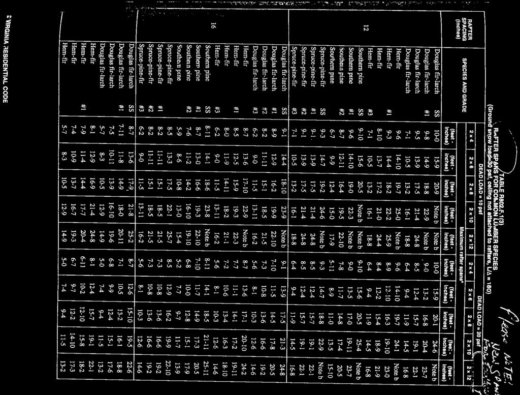
 1 Rafter Size Spacing Allowable span 24" 11'-9" 24" 2x6 14'-1" 2x4 12" 15'-6" 12" 24" 14'-10" 24" 2x8 18'-2" 2x6 12" 20'-5" 12" 24" 18'-2" 24" 2x10 22'-3" 2x8 12" 25'-8" 12" 24" 21'-0" 24" 2x12 25'-9"
10x10 Shed Plans and Building Guide
 Page 1 Legal 2018 Zac Spade & Christopher D. Brown. All Rights Reserved For information about special discounts available for bulk purchases, sales promotions, fundraising and educational needs, contact
Trusted ICC ES PASLODE, Evaluation. report, or as to any. ICC-ES Evaluation
 0 ICC ES Evaluation Report ICC ES 000 (800) 423 6587 (562) 699 0543 www.icc es.orgg Most Widely Accepted and Trusted ESR 3072 Reissued 09/2018 Revised 10/2018 This report is subject to renewal 09/2020.
ICC-ES Evaluation Report Reissued June 1, 2010 This report is subject to re-examination in one year.
 ICC-ES Evaluation Report ESR-2648 Reissued June 1, 2010 This report is subject to re-examination in one year. www.icc-es.org (800) 423-6587 (562) 699-0543 A Subsidiary of the International Code Council
6x6 Shed Plans and Building Guide
 Page 1 Legal 2018 Zac Spade & Christopher D. Brown. All Rights Reserved For information about special discounts available for bulk purchases, sales promotions, fundraising and educational needs, contact
ICC-ES Evaluation Report
 ICC-ES Evaluation Report ESR-6 Reissued April, 009 This report is subject to re-examination in two years. www.icc-es.org (800) 4-6587 (56) 699-054 A Subsidiary of the International Code Council DIVISION:
COMPOSITE RAILING INSTALLATION
 COMPOSITE RAILING INSTALLATION Tools All you ll need is a hammer and screw gun, circular saw (carbidetipped blade with fewer than 20 teeth is recommended), level, tape measure, rasp and blue chalk line.
Joint Evaluation Report
 0 Joint Evaluation Report ICC-ES (800) 423-6587 (562) 699-0543 www.icc-es.org 000 ESR-2909 Reissued 09/2017 This report is subject to renewal 09/2019. DIVISION: 06 00 00 WOOD, PLASTICS AND COMPOSITES SECTION:
WAL-MART SUPERCENTER # ; Milwaukie, OR: SPECIFICATIONS. Revisions to Specification Fence
 MILWAUKIE OR #3144-00 ADDENDUM #5 NARRATIVE: 11-08-12 WAL-MART SUPERCENTER #3144-00; Milwaukie, OR: SPECIFICATIONS SPECIFICATIONS Revisions to Specification 02822 Fence Spec division 02822 has been revised
Deck Designer Specification Kit For AZEK. All rights reserved copyright 2015 AZEK Building Products
 Deck Designer Specification Kit For AZEK All rights reserved copyright 2015 AZEK Building Products Deck layout diagram Top view without planks Bottom view with planks Top view with planks Page 2 Permit
Step 2 - Measure and install joist hangers every 16". See Figure "B" above. Fill every hole in each
 Adding a deck is one of the most useful projects a homeowner can do to improve their home. Each deck is different and presents it's own set of challenges, so contact us with unique questions if they are
IRC 2012 Code Compliant Wood Framed Residential details. Miss Installed Connectors with code references and remedies, discussion.
 IRC 2012 Code Compliant Wood Framed Residential details Miss Installed Connectors with code references and remedies, discussion. You can help avoid this, by being diligent with inspections. Notes to Attendees
Dura-Lock Roof System
 DLR-14 Dura-Lock Roof System Assembly and Installation Instructions Read the instructions before starting the job. They explain the steps required to produce a finished product that will meet factory specifications.
eco-shake INSTALLATION INSTRUCTION
 1 eco-shake INSTALLATION INSTRUCTION NOTE: Shuffling the eco-shakes during installation may be necessary to obtain a uniform color throughout the roof. Due to the natural wood content in the ecoshakes,
Deck Designer Specification Kit For AZEK. All rights reserved copyright 2015 AZEK Building Products
 Deck Designer Specification Kit For AZEK All rights reserved copyright 2015 AZEK Building Products Deck layout diagram Top view without planks Bottom view with planks Top view with planks Page 2 Permit
10x12 FOUNDATION GUIDE 10x12 TRICO AND FLORA SHEDS
 10x12 FOUNDATION GUIDE 10x12 TRICO AND FLORA SHEDS 10x12 WOOD SKID FLOOR FLOOR SYSTEM FOR 10x12 TRICO AND FLORA SHEDS RAW MATERIALS LIST: 2 (9) FLOOR FRAMING AND SHEATHING: 1) BAND BOARD 2 x 6 x 12 PRESSURE
Deck Designer Specification Kit For. TimberTech. All rights reserved copyright 2015 AZEK Building Products
 Deck Designer Specification Kit For TimberTech All rights reserved copyright 2015 AZEK Building Products Deck layout diagram Top view without planks Bottom view with planks Top view with planks Page 2
TCC/SHORE TRANSIT BUS MAINTENANCE FACILITY - PHASE II
 SECTION 061000 - ROUGH CARPENTRY PART 1 - GENERAL 1.1 RELATED DOCUMENTS: A. The General Conditions, any Supplementary General Conditions and Division 1, General Requirements, are hereby made a part of
DECK PERMIT APPLICATION PACKET
 Building Division 865 SE Barrington Dr Oak Harbor, WA 98277 Ph 360.279.4510 Fax 360.279.4519 DECK PERMIT APPLICATION PACKET SUBMITTAL FORMS INDEX Basic Deck Submittal Checklist Residential Deck Submittal
Vertical Offset Base and Safety Rail System Installation Instructions
 Section 5 Vertical Offset Base and Safety Rail System Installation Instructions The vertical offset base and safety rail assembly are designed to be used in residential construction for sloped or flat
Sturdi-Wall Design Manual for SW46, SW66, SW63, SW64, SW60, SW83, SW84, and SW80 Models
 Sturdi-Wall Design Manual for SW46, SW66, SW63, SW64, SW60, SW83, SW84, and SW80 Models Project Number ME086-05 by Brent Leatherman, P.E. Timber Tech Engineering, Inc E-Mail: bl@timbertecheng.com January
DIVISION: WOOD, PLASTICS AND COMPOSITES SECTION: WOOD, PLASTIC, AND COMPOSITE FASTENINGS REPORT HOLDER:
 0 Most Widely Accepted and Trusted ICC ES Evaluation Report ICC ES 000 (800) 87 () 99 0 www.icc es.org ESR 9 Reissued 0/08 This report is subject to renewal 0/09. DIVISION: 0 00 00 WOOD, PLASTICS AND COMPOSITES
IRC 2015 Code Compliant Wood Framed Residential Details. Incorrect Installations of Connectors with code references and remedies, discussion.
 IRC 2015 Code Compliant Wood Framed Residential Details Incorrect Installations of Connectors with code references and remedies, discussion. You can help to avoid this, by being diligent with inspections.
Collins Engineers Palmetto Islands County Park Boardwalk Repairs 03/28/2014 SECTION ROUGH CARPENTRY
 PART 1 GENERAL 1.1 RELATED SECTIONS SECTION 061000 ROUGH CARPENTRY A. Drawings and general provisions of the Construction Contract, including General Conditions and Division 1 Specification Sections, apply
INSTALLATION SHOP DRAWINGS FOR MINNEAPOLIS, MN
 MINNEAPOLIS, MN 2-0- 2-- General Notes Abbreviations Deviations from Architectural Specifications Deviations from Architectural Drawings ALUM. = ALUMINUM B.O. = BY OTHERS CONT. = CONTINUOUS. = CLEARANCE
Deck Designer Specification Kit For. TimberTech. All rights reserved copyright 2015 AZEK Building Products
 Deck Designer Specification Kit For TimberTech All rights reserved copyright 2015 AZEK Building Products Deck layout diagram Top view without planks Bottom view with planks Top view with planks Page 2
STORAGE SHED. Storage Shed SOUTHERN FOREST PRODUCTS ASSOCIATION SOUTHEASTERN LUMBER MANUFACTURERS ASSOCIATION
 STORAGE SHED SOUTHERN FOREST PRODUCTS ASSOCIATION SOUTHEASTERN LUMBER MANUFACTURERS ASSOCIATION P.O. BOX 641700 KENNER, LA 70064-1700 (504) 443-4464 FAX (504) 443-6612 www.southernpine.com Storage Shed
DIVISION: WOOD, PLASTICS AND COMPOSITES SECTION: WOOD, PLASTIC, AND COMPOSITE FASTENINGS REPORT HOLDER:
 0 Most Widely Accepted and Trusted ICC ES Report ICC ES 000 (800) 423 6587 (562) 699 0543 www.icc es.org ESR 3096 Reissued 01/2017 This report is subject to renewal 01/2018. DIVISION: 06 00 00 WOOD, PLASTICS
ROOF-CEILING CONSTRUCTION
 CHAPTER 8 ROOF-CEILING CONSTRUCTION SECTION R801 GENERAL R801.1 Application. The provisions of this chapter shall control the design and construction of the roof-ceiling system for all buildings. R801.2
Installation of Balustrade Systems
 Installation of Balustrade Systems IMPORTANT: Be sure to mark the center point of each newel post's location prior to installation to insure proper spacing. All product interfaces must use PL Premium Adhesive
Installation Instructions for. Before You Begin TOOLS REQUIRED
 Composite Railing System STEP-BY-STEP Installation Instructions for Spectrum Composite Railing Virtually maintenance free 20-year warranty EverNew Spectrum Railing system is designed to work with a number
Deck Designer Specification Kit For. TimberTech. All rights reserved copyright 2015 AZEK Building Products
 Deck Designer Specification Kit For TimberTech All rights reserved copyright 2015 AZEK Building Products Deck layout diagram Top view without planks Bottom view with planks Top view with planks Page 2
PREPARATION & TOOL CHECK LIST
 INSTRUCTION MANUAL RAILING PRODUCTS BEGIN TO AGE AS SOON AS THEY ARE EXPOSED TO NATURE. BUILDINGS EXPERIENCE AGING FACTORS DIFFERENTLY, SO IT IS DIFFICULT TO PREDICT HOW LONG RAILING PRODUCTS WILL LAST.
TREX PERGOLA INSTALLATION INSTRUCTIONS
 RECOMMENDED TOOLS/SUPPLIES: Pencil 4' Level Measuring Tape Framing Square/Speed Square 8' High Step Ladder (Two recommended) Hacksaw or Bolt Cutters Socket Wrench with 9/16" Socket and 3/4" Deep Socket
Deck Designer Specification Kit For. TimberTech. All rights reserved copyright 2015 AZEK Building Products
 Deck Designer Specification Kit For TimberTech All rights reserved copyright 2015 AZEK Building Products Deck layout diagram Top view without planks Bottom view with planks Top view with planks Page 2
INDEX PAGE RELEASE SECTION NUMBER DATE
 INSTALLATION INSTRUCTIONS For Wind Zone 1 (other Wind Zones available on request) Version 11/20/2002 INDEX PAGE RELEASE SECTION NUMBER DATE Approval INTRODUCTION 2 2/26/2001 GENERAL INSTALLATION 3 2/26/2001
ROOF-CEILING CONSTRUCTION
 CHAPTER 8 ROOF-CEILING CONSTRUCTION SECTION R801 GENERAL R801.1 Application. The provisions of this chapter shall control the design and construction of the roof-ceiling system for all buildings. R801.2
SECTION ROUGH CARPENTRY
 SECTION 06 10 00- ROUGH CARPENTRY PART 1 - GENERAL 1.1 RELATED DOCUMENTS A. Drawings and general provisions of the Contract, including Contracting Requirements and Division 1 Specification Sections, apply