Is there sufficient space adjacent the driveway for the gate to slide back onto when open?
|
|
|
- Opal Stokes
- 6 years ago
- Views:
Transcription
1 How to Install a sliding gate from EasyGate Want to install your own automatic sliding gate? EasyGate has all the gear you need to build and install an automatic sliding gate. Note: The information on this page is intended as a guide only representing a typical installation. Dimensions will vary depending on your gate type and running gear setup. What is the width of the driveway? Is there sufficient space adjacent the driveway for the gate to slide back onto when open? Will 240V power be required at the gate or will you install a low voltage system like the EasyGate 24v Boxer motor which can operate with the 240v upto 100m away or solar powered? Is the driveway the only entrance to the property? If YES - Will a pedestrian gate be required? If YES - Consider installing battery backup such as the EasyGate Boxer motor to ensure your gate remains operational if you have a power blackout. Is there a fall across the driveway from left to right? I.e. is the ground under the gate level? To workout the fall run a string line that is level across the driveway and check the difference at each end. If you have a significant fall you will need to add a minimum 25% extra in your weight calculations for the motor. What type of design would you like for your gates? You can view some of EasyGate gate designs. Click on Sliding Gates under the main picture of the home page. Estimate the approximate weight of the gate. Take into consideration that with solid gates (sheeted gates you can't see through) the power needed to drive the gate increases because of the increased weight and wind load (friction) on the gate. Allow a minimum 25% extra in your weight calculations. The average person can lift 70 kgs so 4 people will lift 280kgs. This is a medium gate. Gates over 400kgs are considered heavy and gates under 200kgs are light. EasyGate alloy gates are light to medium but very strong so the Boxer motor will push it with ease. What surface is the driveway? The surface needs to be continuous concrete for double the width of the driveway and generally mm across. The depth of the footing will be dependent on soil conditions and traffic weights. Things to consider when you are having your gate built; Aluminium gates are light weight, strong and will not corrode in hash conditions such as sea side locations. They are easy to install and will not need expensive heavy duty openers and are easy on the running gear wear and tear. Steel gates are strong but heavy and need to be zinc coated prior to powder coating if you want them to last as long as alloy. The bottom rail needs to be no less than 75mm high. EasyGate Manor gates have a 100mm x 50mm bottom section and are made from aluminium. A support post of no less than 75x75 RHS is required, preferably 100 x100 and concreted into the ground. Ensure a catcher bracket is installed in the closed position and a top guide bracket fitted to the top of the post above your automation motor to hold the gate vertical. This will help prevent it being pushed over. Always install a stopper at the bottom of the gate in the fully open position to prevent over running. Basically the gate must run well manually before installing automation. The test we use is that you must be able to 1
2 open the gate with two fingers while slowly walking (on level ground). If your installation is on a slope please ring EasyGate on to discuss what will work best. Do you want the gate to automatically close behind you when you drive in or out? All EasyGate gate openers have this feature. If NO - you will press your hand transmitter once to open the gate and then press it again to close it. If YES - a conduit will need to be installed between the motor position and the catch post. If this is not possible a 5mm slot will need to be cut into the concrete parallel to the edge of the sliding gate track. This will allow for the installation of optional Safety Beams which will prevent the gate closing on obstacles such as you car. How will visitors enter or let you know they have arrived if there is no pedestrian entry? We recommend the EasyGate Keypad for the outside of the property and the EasyGate Exit Button on the inside of the property as standard. Place your mobile number next to the keypad (plastic name badge will do fine) and the visitor can ring you for access. Audio/Visual Intercom - you can have a combination of video monitors and audio handsets to suit your requirements. We recommend the EasyGate Kocom Audio intercom Do you need access back out through the gate without your remote control while gardening or walking the dog? A keypad is a good option here as with the entry but a keyed exit button is also a common addition placed inside your property so that you can press it from the car window. In-depth look at Planning a sliding gate installation; The more time you spend at this stage the less mistakes are made and time wasted doing re-work, so spend a bit of time getting this part right. Any sliding gate has only a few key points that need consideration - the track, the gate, guide support post or pier, receiver post or pier and the catcher. Granted, the automation section has many more considerations but just for the moment let's concentrate our planning on the basics as they remain constant whether the gate is automated or not. The first thing we need is two definable points to determine our gate opening. You may have existing posts, brick or concrete piers. If not you will need to allow for the installation of posts or piers to act as a receiver or catcher on closing and guide support bracket to stop the gate from falling over. If you are installing new posts I would suggest 75mm -100 mm square as a good size and if concreting into the ground a minimum of 600mm in concrete with legs attached. 2
3 Once we have determined our two points we can start to look for and record some information - 1. The opening width between our two posts or piers. 2. This will give us a width for our gate called the FRAME LENGTH - usually this is the opening width plus 50mm overlap on the receiver side plus overlap on the guide / roller side, typically 100mm for a manual gate or 300mm for an automated gate. 3. Once we have a total gate width we can check to ensure sufficient room to slide open fully without impeding the opening. Now that we have worked out where our gate will slide we can determine the track position. The track centre will run approx. 75mm from the face of your posts or piers when using a standard EasyGate of 50mm thick. When your gate is thicker than this you will need to adjust the track centre to suit. Concreting In Posts; Sounds simple enough I hear you say but poorly installed posts account for 90% of all gate problems. If the post moves, the gate fails it s that simple! Start with your post. As a good guide one third of your post should be in the ground. In other words if the finished gate post is 1800 high from the ground your total length is now A minimum of 600mm should be in the ground. Fit a leg or two to your post. A post without any cross braces or legs to anchor the post in the concrete will simply slide out of the concrete when dry or worse still may sink down if no concrete has been put underneath. Put at least on decent cross brace about 300mm up your post and about 150mm wide or place a tile under the post. Dig your hole deep, not round. A common mistake is to dig a one metre by one metre hole but only 400mm deep. Do not. 400mm x 400mm x 1000mm deep is much better and takes less than half the concrete. The simplest way to mix your concrete is to buy the premix concrete packs at your local hardware. They are inexpensive, the mix is accurate and strong and they only take 5 minutes to mix in a bucket. Just add water. Most posts require about four 35kg bags. DO NOT USE QUICKSET, RAPIDSET OR ANY OTHER FAST DRYING CONCRETE. These work fine in static fence posts but will quickly come unstuck when a big hinged gate starts swinging on the post. Where they can be handy is your very first mix in the bottom of the hole. This allows you to set your height and squareness while the concrete sets and stops any further movement whilst you complete your concreting. Gate Construction; We will cover here basic, or more correctly, common gate construction. There are countless ways to construct your gate that would take a complete book if you included drawings etc. The easiest place to start is the bottom rail of the gate. The bottom rail is generally 100x50mm RHS such as the EasyGate Manor Gates. This will give you more overall strength and added room if installing your motors gear rack at the bottom although 50x50mm RHS is perfectly acceptable on short gates under 3.5m. Light weight gates can be made from 1.6mm wall thickness whilst wide gates should be 2.5mm -3mm wall thickness such as the EasyGate manor gates. Sides and top are typically 50x50mm.Gate fill is obviously a personal choice. A gate using a centre fill contained within the main frame and a gate using a front surface mounted fill like pickets or spears. A pair of wheels will need to be installed at 25% in from each end of the gate. There are 2 types of wheels available. Trapeze (high profile) is a wheel that bolts directly under your gate while Support (low profile) wheels need to be inserted into your bottom spin rail of the gate so only a portion of the wheel is exposed. 80mm diameter wheels for short (under 3.5m) light gates and 100mm for larger heavy gates. You have a choice of V shape or U shape depending on your personal preference but U shape is better suited to driveways with small stones then V but apart from that they will both do the job. How to fit wheels to your sliding gate To attach the wheels to the gate you must decide on a suitable position you wish to place the wheel in from the end. 3


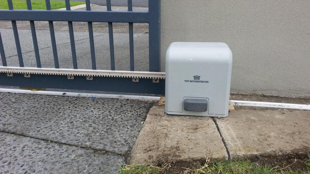
4 The most common is about 1m and in the centre of the vertical round bars. If your concrete is uneven then you may need to go further in so as the centre of the gate does not hit the wheel track. Option 1: Support Wheel Depending on the position of the cradle determines the width of the cut hole in the gate. Note: EasyGate sliders are supplied with the wheel space already cut and wheels fitted. Only cut a rectangle hole big enough to fit the portion of the wheel required. This is done using a simple hand grinder with a cut off blade once you have marked the hole with a marker or tape. Place the gate at 45 degrees on 2 x trestles so you can safely cut the holes. Be sure to protect the gate from damage with soft mats or do it on grass. When cutting the hole you will not need to cut right up to the corners with alloy but near enough...use a hammer and punch to tap the excess rectangle into the gate and remove it once free from the corners. Fit the wheel into the hole and check for free running. Use standard fasteners to secure the wheel to the gate. Option 2: Trapeze Wheel Track basics; Perhaps the two most basic fundamentals of a sliding gate are a) straight and b) consistent. I say consistent because it is not necessary for a track to be level left to right, but it must be consistent. In other words, if your driveway has a consistent drop from one side to the other of say 200mm, then the run off portion of your track must also fall 200mm so that the entire track, which is twice the length of your gate opening falls a consistent 400mm. No rises and falls but a smooth, consistent drop. Straight is pretty much common sense. The centre of your track should generally be about mm from your guiding post or pier for a 50mm thick gate. This dimension will vary dependent on your gate thickness roller configuration. What type of track; 1. Bolt Down Track; By far the most preferred method and is what all EasyGate sliders come with. This type of track assumes you have a surface suitable to bolt down to. Usually an existing concrete driveway or in some rare cases well secured and level brick paving will suffice if traffic flow is not heavy or constant. Most professional installers prefer to lay a full concrete plinth and then bolt down the track. Their argument is that using bolt down track gives them flexibility and allows a section to be replaced if damaged. When bolted down to an existing driveway it is not unusual to see the back edge of the track or "run off" section with brackets or legs at 500mm intervals 4


.")


5 either bolted to an existing wall or concreted at footing points (see photo below). This is acceptable in most cases as there will be no traffic over this section and will carry the gate only. To secure your wheel track EasyGate provide concrete anchor pins with your gate and even include the drill bit! 2. Full concrete plinth allowing for driveway completion; This is simply a concrete plinth poured to give allowance for driveway finishing and be the foundation to your wheel track, be it a brick paving header course or Asphalt etc. A few different levels can be used to achieve different finished results (see below). This track has maximum strength due to the reinforcing and the run off area of the track is also well supported by the reinforcing. Guide Bracket; Once the wheel track is positioned you can install the guide bracket above the gate. Positioned on the post behind the motor this bracket is to prevent the gate from falling over and guide it left and right. For small light gates less then 3.1m a 2 x roller guide bracket will do and a 4 x roller for all others. Gate Catcher or receiver; Positioned on the post at the closed gate end the Gate Catcher guides the gate to the closed position and prevents the gate from being lifted off the track. There are 2 types of gate catchers. The standard butt catcher is used for positions that the gate will butt upto the post and the side mountable catcher for gates that will pass the end post which are positioned in-line with the centre post. The EasyGate Side Catcher is fitted with 2 rollers and can be adjusted up and down as well as sideways giving a higher level of installation options. Gate Stopper; Positioned on the ground to the rear of the fully open gate to stop the gate running off the wheel track or guide bracket. This is an important safety device that should be installed. 5
6 6
7 7
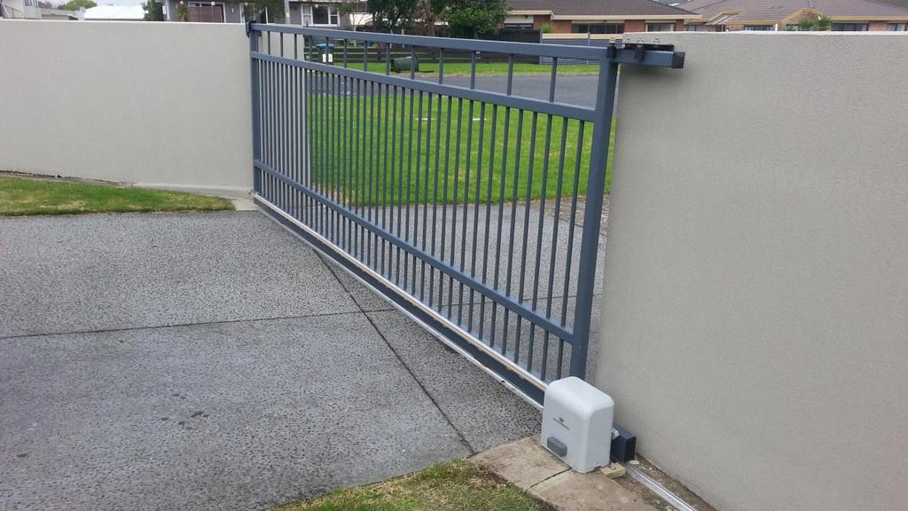
8 Do not fit wheels in the middle of the gate. If the ground drops off the edge of the driveway a steel rail can be used to support the gate track. Guide systems for Sliding Gates 8

9 Sliding Gates require a guide system to hold the gate up as it moves, the simplest being a guide roller either side of the gate. Open Hard Stopper The gate must also be prevented gate over running off the guide system and fall over, which can be dangerous and damaging. 9

10 Mounting your motor and gear rack; The most common method of motor mounting is to bolt down to a pre prepared concrete pad although most motors have a base plate available that can be installed in concrete beforehand with your track work making the bolt down procedure even simpler. Use a length of rack to position your motor in relation to the gate and take into account limit switch positioning. Once you have bolted the motor down securely use your manual override to put the gate into manual mode. Start at one end and use tek screws (supplied) to fasten your first length of rack centred over the pinion or sprocket. The rack should not sit directly on the pinion but have a 1-1.2mm gap between the pinion and the rack. Use a 1-1.2mm spacing washer under the 4 corners of the motor base plate while installing the gear rack, then remove these to do the final setup. Slide the gate back and forth to ensure the first length is level. You can now slide the gate along until the pinion is about 80mm from the end of the first length of rack. Attach the next length of rack into the interlocking point of the first length of rack and position the other end of the rack on the pinion. You should now be able to fasten this length of rack at two points and move along to the next and subsequent lengths. You may need to cut the last length to suit. When all lengths are fitted, remove the spacing washers and re tighten the motor to the ground. Check the operation of the rack before inserting all fasteners. Ready to power and program; At this point I assume you have had your power connected and all other wiring has been completed. My simple suggestion here is that you leave most extras like photo cell beams and keypads not connected, and have all required control board connector block wire loops installed until after you finish programming and have your gate running smoothly. Having bells and whistles connected will only complicate matters if things don't go exactly as expected. By having the bare basics makes fault finding much easier. For further information please visit the EasyGate website info@easygate.co.nz. Ph
TELESCOPIC GATE MANUFACTURING AND INSTALLATION MANUAL.
 TELESCOPIC GATE MANUFACTURING AND INSTALLATION MANUAL. Telescopic gates have been manufactured for many years essentially in the same way they are largely today. In recent years hardware suppliers have
E N G L I S H GARDEN SHED. Assembly Instructions. Suitable for Models WITH VARYING DEPTHS
 GARDEN SHED Assembly Instructions Suitable for Models 6' Wide 8' Wide 0' Wide WITH VARYING DEPTHS GI0003 November 0 INSTALLATION ADVICE It's Not That Difficult! The construction of your shed isn't as complicated
CertainTeed INSTALLATION GUIDE SIMTEK FENCE PRODUCTS. Fence Installation Guide 3', 4' & 6' High
 CertainTeed INSTALLATION GUIDE SIMTEK FENCE PRODUCTS Fence Installation Guide 3', 4' & 6' High INSTALLATION GUIDE These instructions are designed to assist both professional installers and do-it-yourselfers
Swerve Rack CUSTOM RACKS AVAILABLE
 CUSTOM RACKS AVAILABLE Swerve Rack The design of the Swerve mirrors the bike frame, thus providing superior bike support while making it easy to secure both the bike frame and wheel with a standard u-lock.
Good Neighbour INSTALLATION GUIDE GOOD NEIGHBOUR FENCING BEFORE YOU START TOOLS AND HARDWARE REQUIRED
 INSTALLATION GUIDE Good Neighbour GOOD NEIGHBOUR FENCING Stratco Good Neighbour fencing is both strong and attractive. Its design allows clean and uncluttered lines to be enjoyed by neighbours on both
Downtown Rack. Custom logo option available
 Custom logo option available Downtown Rack The Downtown Rack uses thick, square-tube construction that can t be cut with a pipe cutter. The extended width of the Downtown Rack makes for easy bike parking
GOOD NEIGHBOUR FENCING INSTALLATION GUIDE GOOD NEIGHBOUR FENCING BEFORE YOU START TOOLS AND HARDWARE REQUIRED
 GOOD NEIGHBOUR FENCING Stratco Good Neighbour fencing is both strong and attractive. Its design allows clean and uncluttered lines to be enjoyed by neighbours on both sides of the fence. Good Neighbour
10x10 Trellis Pergola
 0x0 Trellis Pergola ASSEMBLY GUIDE Ver.-007 Table of Contents PAGE 0x0 Trellis Pergola Introduction & Overview...................................................... Pergola Materials Overview..............................................................
FENCE INSTALLATION GUIDE 8 HIGH WALLS
 FENCE INSTALLATION GUIDE 8 HIGH WALLS 1.866.648.9336 www.simtekfence.com INSTALLATION GUIDE These instructions are designed to assist both professional installers and do-it-yourselfers of SimTek decorative
10x10 Trellis Pergola
 0x0 Trellis Pergola ASSEMBLY GUIDE Ver.0-7 Table of Contents PAGE Introduction & Overview...................................................... Pergola Materials Overview..............................................................
Installation Instructions. Tools Needed. Tape measure. Level. Shovel or Post hole digger. Concrete. Drill. Stakes. Mallet or hammer.
 Installation Guide EcoStone Fence 1330 West 400 North Orem, UT 84057 Toll Free 1.866.648.9336 Tel. 1.801.655.5236 Fax 1.801.655.5240 www.ecostonefence.com Installation Instructions Introduction. These
The Queen Quilter Professional Quilters Kit Frame
 The Queen Quilter Professional Quilters Kit Frame Assembly Instructions Table of Contents: Before you begin......................... Pg. 2 Wood parts............................. Pg. 3 Hardware..............................
Greenhouse Assembly Instructions
 Greenhouse Assembly Instructions Our Help Line provides support and advice to customers of Summer Garden Buildings after ordering. For advice before you buy you can phone us free 7 days a week on 0800
BUMP GATE FITTING INSTRUCTIONS.
 1 BUMP GATE FITTING INSTRUCTIONS. HEAVY DUTY MODEL FOR STEEL POSTS. Hinge post Lock post Bump arms Two-way lock Thank you for purchasing a Bump Gate. This device will provide you with many years of good
Gardman Lean-to Greenhouse Assembly Instructions
 Page 1 Gardman Lean-to Greenhouse Assembly Instructions Our Help Line provides support and advice to customers of Summer Garden Buildings after ordering. For advice before you buy you can phone us free
WARNING: Prior to installation, turn the power off to the vending machine and unplug it from its power source. Also, make sure to level the machine.
 Installation of Gum and Mint Tray for National 147, 157, 167 Important Note: Please read all instructions thoroughly before continuing with installation of kit. If you are having problems installing the
HOOP RACK HEAVY DUTY Setbacks WALL 36" WALL 42" 36" STREET 59" STREET Dero
 Setbacks WALL 36" WALL 42" STREET 36" 59" STREET Installation Instructions Tape Measure Marker or Pencil Masonry Drill Bit Drill (Hammer drill recommended) Hammer Wrench 9/16 Level RECOMMENDED BASE MATERIAL
Spiral Slide
 IMPORTANT Page 1 PLEASE READ THESE INSTRUCTIONS BEFORE COMMENCING ASSEMBLY. All equipment must be installed in accordance with these instructions. Check your shipment against Bill of Lading and Parts list.
FENCE INSTALLATION GUIDE 6 HIGH FENCE
 FENCE INSTALLATION GUIDE 6 HIGH FENCE 1.866.648.9336 www.simtekfence.com INSTALLATION GUIDE These instructions are designed to assist both professional installers and do-it-yourselfers of SimTek decorative
SteelChief Installation Instructions for pre-assembled panel form sheds GABLE ROOF
 SteelChief Installation Instructions for pre-assembled panel form sheds GABLE ROOF Please read fully before commencing work...any queries will be promptly answered, contact theboss@steelchief.com.aui MPORTANT
Aluminum. Fence Systems
 Aluminum M Fence Systems Lifetime Warranty Aluminum Fence Systems Gates & Hardware The Morgan Series Aluminum Fence System is manufactured of the highest quality aluminum and all parts of the system are
INSTALLATION MANUAL. 2. Check with local utility companies for locations of underground cables or pipe lines.
 INSTALLATION MANUAL Install our maintenance free fencing system yourself! About 90% of our residential clientele install our fencing systems themselves. Why hire and pay someone to install it when you
ALUMINUM. Fence Systems. Made. in the USA
 Aluminum Fence Systems Gates and Hardware Made in the USA ALUMINUM M Fence Systems Lifetime Warranty KeyLinkFencing.com Table of Contents Gates and Hardware 3 Morgan Accessories 3 4000 Series 4 & 5 2000
Installation Guide. Step-by-Step Guide
 Installation Guide Step-by-Step Guide Thank you for choosing one of our quality products. We are the industry leaders in designer panel fencing. This product will provide you with years of trouble free
H O O P RAC K. Simple Security
 H O O P RAC K Simple Security The Hoop Rack is a proven design that provides high security and easy bike parking. The Hoop Rack uses thick pipe construction and the full radius of the bend makes the Hoop
INSTALLATION GUIDE DUOFUSE SLAT WALL SYSTEM
 06/2013 ENG 1 INSTALLATION GUIDE DUOFUSE SLAT WALL SYSTEM The Duofuse wood composite slat wall system is much more durable than wooden fences, and correct installation is necessary to enjoy the fences
EASY-IN POOL STEP SYSTEM NE132
 EASY-IN POOL STEP SYSTEM NE132 This instruction manual features multiple guides for the step unit components. 7939 EASY POOL STEP (NE113) FOR USE WITH: EASY-IN POOL STEP (NE126) 6492 PARTS & HARDWARE FOR
IMPORTANT!!! ASSEMBLY ASSEMBLY INSTRUCTIONS. (Internal Dimensions)
") ASSEMBLY ASSEMBLY INSTRUCTIONS (Internal Dimensions) Ent Spec Edition Ltr v-0- Overall dimensions including base: 7. L x 9 W x 0 H cms 97.5" L x 7" W x 8.7" H IMPORTANT!!! Please read these instructions
ASSEMBLY ASSEMBLY INSTRUCTIONS (Internal Dimensions) Ent Spec Edition Ltr v-0- Overall dimensions including base: 7. L x 9 W x 0 H cms 97.5" L x 7" W x 8.7" H IMPORTANT!!! Please read these instructions
LAWN AND GARDEN GREENHOUSE
 MODELS# OG0AL8-BKE OGAL-8 OGrow Walk-in ' x 8' LAWN AND GARDEN GREENHOUSE With Heavy Duty Aluminium Frame MANUAL VERSION # Grow r! e h t e g To Let's Thank you for purchasing the OGROW greenhouse Follow
END FRAMES. End frames built using pressure treated 2x4 (1 1/2" x 3 1/2") 36" 34" 7/16" pilot hole. 5 1/2" x 1/2" lag bolt 8" wheel 23"
 36 34 7/16 pilot hole. 5 1/2 x 1/2 lag bolt 8 wheel 23") END FRAMES End frames built using pressure treated 2x4 (1 1/2" x 3 1/2") 23" 17 1/2" (B) (B) Measure from the bottom of your stone to 1" below the lip to get your measurement. 17 1/2"(B) 36" 34" 1/2" flat
END FRAMES End frames built using pressure treated 2x4 (1 1/2" x 3 1/2") 23" 17 1/2" (B) (B) Measure from the bottom of your stone to 1" below the lip to get your measurement. 17 1/2"(B) 36" 34" 1/2" flat
Clopay Models 835/837 Sliding Door System Installation Guide
 Clopay Models 835/837 Sliding Door System Installation Guide The aim of this instruction is to guide you through the process of construction and fitting of Sliding Doors. Due to the number of sizes available
Installa on Guide: Fence Distributors. YourNextFence.com
 TM YourNextFence.com Plan Your Fence each line by dividing the length of each line in inches by 97. Round any remainder up. 2 Calculate Materials Tools Needed Stakes Circular Saw String Line Drill Marking
INSTALLATION MANUAL. 2. Check with local utility companies for locations of underground cables or pipe lines.
 INSTALLATION MANUAL Install our maintenance free fencing system yourself! About 90% of our residential clientele install our fencing systems themselves. Why hire and pay someone to install it when you
PVC Fencing Install Instructions
 PVC Fencing Install Instructions Step 1-Pounding the Galvanized Steel Posts Call your local area utility company to come mark underground lines before any digging or pounding any posts into the ground.
Taurean Sectional Garage Door INSTALLATION INSTRUCTIONS
 BEFORE YOU BEGIN MAKE SURE THESE INSTRUCTIONS ARE READ AND UNDERSTOOD COMPLETELY. THESE INSTRUCTIONS ARE INTENDED FOR PROFESSIONAL GARAGE DOOR INSTALLERS. ALL REFERENCES ARE TAKEN FROM THE INSIDE LOOKING
Piazzola Pergola Awning Manufacturing and installation guide
 Piazzola Pergola Awning Manufacturing and installation guide Date Changes Page General information Maximum and minimum width Width Projection 150 to 349 cm 350 to 500 cm From 200 to 250 cm X From 251 to
LAWN AND GARDEN GREENHOUSE
 MODEL# OGAL-66 OGrow Walk-in 6' x ' LAWN AND GARDEN GREENHOUSE With Heavy Duty Aluminium Frame Let'sGrow Together! Thank you for purchasing the OGROW greenhouse Follow the assembly and safety instructions
Installation Instructions - Model V4JSD 1
 Installation Instructions - Model V4JSD 1 Support Assemblies: Parts list: (Note see enclosed cut sheet for quantities and dimensional information) A vertical structural member (1 ½ x 1 ½ modular frame)
Assembly instructions. 6x4. Model GH1354A. 6x6. Model GH1357A. 6x8. Model GH1360A. 6x10. Walk-in Greenhouse. Model GH1363A
 ssembly instructions x Model GH x Model GH7 x8 Model GH0 x0 Model GH Walk-in Greenhouse Statement ear Customer! May we congratulate you on your new Greenhouse. We feel sure that by following the detailed
INSTALLATION INSTRUCTIONS for the JOMY RETRACTABLE LADDER. If there are any questions, please call (800)
") INSTALLATION INSTRUCTIONS for the JOMY RETRACTABLE LADDER If there are any questions, please call (800) 255-2591 INSTALLATION INSTRUCTIONS WARNING! Ladder Sections Lock When Closed. Do Not Install or Close
INSTALLATION INSTRUCTIONS for the JOMY RETRACTABLE LADDER If there are any questions, please call (800) 255-2591 INSTALLATION INSTRUCTIONS WARNING! Ladder Sections Lock When Closed. Do Not Install or Close
FRAMELESS GLASS FENCING DIY GUIDE
 FRAMELESS GLASS FENCING SITE MEASURE 1. Planning is the first step of any successful project. 2. We have a large range of sizes to allow for varying site requirements. 3. Simply decide where you would
MODEL No: GSS3030G. Model No:...GSS3030G Overall Size (W x D X H*) x 3000 x 2100mm Roof Type:...Gable *Minimum Wall Height
 x 3000 x 2100mm Roof Type:...Gable *Minimum Wall Height") 1. SAFETY INSTRUCTIONS INSTRUCTIONS FOR: GALVANIZED STEEL SHED GREEN 3 x 3 x 2.1m MODEL No: GSS3030G Thank you for purchasing a Sealey product. Manufactured to a high standard, this product will, if used
1. SAFETY INSTRUCTIONS INSTRUCTIONS FOR: GALVANIZED STEEL SHED GREEN 3 x 3 x 2.1m MODEL No: GSS3030G Thank you for purchasing a Sealey product. Manufactured to a high standard, this product will, if used
H HD Adult Wheelchair Swing Frame & Hangers(perm) IMPORTANT
 IMPORTANT") Page 1 IMPORTANT PLEASE READ THESE INSTRUCTIONS BEFORE COMMENCING ASSEMBLY. All equipment must be installed in accordance with these instructions. Check your shipment against Bill of Lading and Parts list.
Page 1 IMPORTANT PLEASE READ THESE INSTRUCTIONS BEFORE COMMENCING ASSEMBLY. All equipment must be installed in accordance with these instructions. Check your shipment against Bill of Lading and Parts list.
ASPEN STYLE. ORNAMENTAL GATE INSTALLATION GUIDE 3 Rails, Pressed Top/Flat Bottom Model No. EGBR5842-N2P
 1 ASPEN STYLE ORNAMENTAL GATE INSTALLATION GUIDE 3 Rails, Pressed Top/Flat Bottom Model No. EGBR5842-N2P INSTALLATION VIDEO AVAILABLE AT: video01.xcelfence.com Item Description Gate installation and assembly
Insolroll Clutch Operated Shades Installation Instructions Installation Instructions
 All clutch operated shades are shipped fully assembled and ready for installation. Mounting screws are not provided. Screws for chain guide installation to meet the child safety standards are provided.
Installation Guide. Capped Cellular PVC Fencing. Table of Contents. Storage and Handling Tools Needed Fence Layout and Locating Posts
 Capped Cellular PVC Fencing Installation Guide Table of Contents Storage and Handling Tools Needed Fence Layout and Locating Posts Installation instructions 4 x 4 Over Sleeve Post - 3.5 Rail Privacy Shadowbox
Residential Fencing Picket. Installation Guide
 Residential Fencing Picket. Installation Guide Jabiru Picket Fence White Contents Getting Started 4 Installation Tips 4 Shortening a Panel Tools Required 5 Instructions 6 3 Getting Started Congratulations
Sectional Door Installation Instructions
 Sectional Door Installation Instructions 1. Check opening height and door size. a. 25-30mm overlap on each side and >10mm at top. b. At least 150mm side room required 2. Check headroom clearance, standard
Assembly Instructions 10 X 10 Aluminum Roof Support
 Assembly Instructions 10 X 10 Aluminum Roof Support Aluminum Roof Support Bolt Package 16-5/16 X 2 ¼ SS Bolt 24-5/16 X 1 SS Bolt 40-5/16 SS Nylon Lock Nuts 16-5/16 SS Flat Washers 28-4 ½ Wood Screws 36-1
Flex Fence Instruction Manual
 The Safer Stronger Smarter Choice Flex Fence Instruction Manual Table of contents 2 3 4 4 5 5 6 7 8 10 10 11 11 12 13 13 15 18 18 19 20 22 Table of contents Supplies, tools and equipment Introduction Laying
Installa on Guide: Fence Distributors. YourNextFence.com
 YourNextFence.com Plan Your Fence each line by dividing the length of each line in inches by 96. Round any remainder up. 2 Calculate Materials * For standard single gates (46 1/4 opening) : (1) small Trex
DIY GLASS BALUSTRADE AND POOL FENCING THE CHOICE IS SIMPLE
 DIY GLASS BALUSTRADE AND POOL FENCING THE CHOICE IS SIMPLE SAFE STYLISH AND AFFORDABLE FOR DIY GLASS FENCE SOLUTIONS THE CHOICE IS SIMPLE Bring your outdoor areas to life with clear views and clean lines.
400A 40113V, 401A 40120V, & 401AL 40120VL ALUMINUM VERTICAL 4000 LB LIFT INCLUDES SCREW LEG ASSEMBLY INSTRUCTIONS
 12/11/07 PAGE 1 OF 12 400A 40113V, 401A 40120V, & 401AL 40120VL ALUMINUM VERTICAL 4000 LB LIFT INCLUDES SCREW LEG ASSEMBLY INSTRUCTIONS Thank you for purchasing our product! *Please read these instructions
FENCE INSTALLATION GUIDE 3, 4, & 6 HIGH FENCE
 FENCE INSTALLATION GUIDE 3, 4, & 6 HIGH FENCE 1.866.648.9336 www.simtekfence.com INSTALLATION GUIDE These instructions are designed to assist both professional installers and do-it-yourselfers of SimTek
RUN-IN SHED INSTRUCTIONS
 RUN-IN SHED INSTRUCTIONS 14321 5th Line Nassagaweya, Rockwood, ON, N0B 2K0 Phone 519-856-9959 ~ Fax 519-856-4141 Toll Free 1-800-461-3362 ~ Email sales@systemhorse.com Website www.systemfence.com RUN-IN
 SUPREME WALL GARDEN ASSEMBLY INSTRUCTIONS 24/08/16 www.hallsgreenhouses.com Please refer to website for the most up to date instructions. SAFETY WARNING 1. Always wear protective glasses, shoes, gloves
UNIVERSAL PANEL AND GATE
 PVC Fencing / Residential Style UNIVERSAL PANEL AND GATE INSTALLATION INSTRUCTIONS Fencing Without Boundaries TM 1 BEFORE YOU START, IT S IMPORTANT TO CHECK......That fence footings do not exceed legally
SHADOWBOX INSTALLATION FOR: Standard 6 H x 8 W Shadowbox Fence 5 x 5 Routed Posts Dog Ear or Straight-Edge Pickets 1.75 x 3.5 Rail
 SHADOWBOX INSTALLATION FOR: Standard 6 H x 8 W Shadowbox Fence 5 x 5 Routed Posts Dog Ear or Straight-Edge Pickets 1.75 x 3.5 Rail Storage and Handling Fence Preparation and Layout Locate and Set Posts
Woodline USA Woodline Spacer Fence System
 Woodline USA Woodline Spacer Fence System MADE IN THE USA Includes: (1) ¼ Spacer Fence (1) 3/8 Spacer Fence (1) ½ Spacer Fence (1) Hardware Package (1) 3 Piece Brass bar set (2) Setup Blocks Visit Us Online
CONTENTS TOOL LIST U P S I D E I N N O V A T I O N S, L L C RAMP AND STEP SYSTEM ASSEMBLY INSTRUCTIONS. Revised: June 2013
 U P S I D E I N N O V A T I O N S, L L C RAMP AND STEP SYSTEM ASSEMBLY INSTRUCTIONS TOOL LIST Required Tools: - Reciprocating Saw with Metal Cutting Blade - Drill - 7/16 Drill Bit for Metal Drilling -
How To Measure Your Finished Opening
 3000 Series Bifold Doors How To Measure Your Finished Opening MEASURE FROM RIGHT TO LEFT 2 PLACES (WIDTH) MEASURE FROM TOP TO BOTTOM 2 PLACES (HEIGHT) Tools Required for Assembly: Tools Needed: Phillips
Assembly Instructions
 Unite Panel System Hinge Door July 2016 #12 x / slotted hex washer head bolt Figure 1 threshold bracket frame Detail F threshold bracket threshold bracket (installed) #12 x / slotted hex washer head bolt
Ranch Rail Vinyl Fence
 Ranch Rail Vinyl Fence INSTALLATION INSTRUCTIONS These instructions are to be used as general guidelines for the installation of your vinyl fence under normal installation conditions. Local conditions
SLIDING GATES BRUNDLE
 SLIDING GATES BRUNDLE 32 BRUNDLE TOOTHED GATE RACK & ACCESSORIES TO BE WELDED TO GATE. GALVANISED OR SELF COLOUR IN ROLLED STEEL FOR GATES UP TO 1800KG Rack 22 x 22 H Art L H T L T Self Colour Self Colour
GALVANIZED SHED GREEN 2.3 X 2.3 X 1.9m
 INSTRUCTIONS FOR: GALVANIZED SHED GREEN 2.3 X 2.3 X 1.9m MODEL NO: GSS2323G Thank you for purchasing a Sealey product. Manufactured to a high standard, this product will, if used according to these instructions,
Vinyl Fence Installation Instructions. Privacy Fence Installation Instructions
 Privacy Fence Installation Instructions Tips Before You Start - Read this instruction sheet completely. - During fence assembly, work on a soft, non-abrasive surfaces where possible to avoid - scratching
Installation Manual for Gate Guard
 Installation Manual for Gate Guard Fast Opening Barrier Gate for Emergencies and Contra Flow Innovative safety technology from SGGT of Germany TABLE OF CONTENTS Page Number Preface 3 Introduction 3 System
Stage 2: Preparing the door (read in conjunction with Hole Drilling Options on back of Template).
.") There are three stages to fitting the CL100 mortise case: Stage 1: Marking out the position of the lock. Stage 2: Preparing the door by mortising and drilling holes. Stage 3: Fitting lock, door furniture,
There are three stages to fitting the CL100 mortise case: Stage 1: Marking out the position of the lock. Stage 2: Preparing the door by mortising and drilling holes. Stage 3: Fitting lock, door furniture,
Heavy-Duty Bypass Track System
 Heavy-Duty Bypass Track System Please Note: This track system must be installed with the screws going into a solid surface such as studs or a header. Due to the spacing of the holes on these Brackets,
ClearSpan End Frame Kit 26' Wide x 12' High
 ClearSpan End Frame Kit 26' Wide x 12' High Diagram shows the end frame kit for an end wall without a door. (Door and end panel are purchased separately.) Rafter and struts shown in the above diagram are
Oxford Stalls Installation Instructions
 Oxford Stalls Installation Instructions RAMM Horse Fencing and Stalls 13150 Airport Hwy. Swanton, OH 43558-9615 1-800-434-8456 Rev. 8/15/17 Before You Start Typical stall sizes are 10 x 10, 12 x 12 or
640D & 650D SERIES FRAMED BYPASS BATH ENCLOSURES
 INSTALLATION INSTRUCTIONS 640D & 650D SERIES FRAMED BYPASS BATH ENCLOSURES 800-643-1514 www.alumaxshowerdoor.com Page 1 !WARNINGS! INSTALLATION WARNINGS a) Alumax Bath Enclosures by Sapa are intended to
SECTION 19: Endwood Fusion Welded Gate Installation Guide
 SECTION 19: Endwood Fusion Welded Gate Installation Guide ASSEMBLY AND INSTALLATION FOR: Fusion Welded Gates Gate Frame with Full Size Pickets Privacy & Board on Board California & Shadowbox Gate width
PRIVACY FENCE WITH LATTICE INSTALLATION INSTRUCTIONS
 PRIVACY FENCE WITH LATTICE INSTALLATION INSTRUCTIONS These instructions are to be used as general guidelines for the installation of your vinyl fence under normal installation conditions. Local conditions
Carousels - Overlapping Slat
 Carousels - Overlapping Slat Introduction The overlapping slat carousel is designed to re-circulate baggage through a series of rectangular shaped slats overlapped and linked to form a continuous loop.
Gable HomeshedsTM INSTALLATION BEFORE YOU START TOOLS REQUIRED GUIDE LARGE SPAN. Council Approval. Before Starting
 INSTALLATION GUIDE Gable HomeshedsTM LARGE SPAN BEFORE YOU START Council Approval It is important to contact your local council before building your Stratco Gable Homeshed. You will have already received
S H E D A S S E M B L Y I N S T R U C T I O N S
 T I T A N R A N G E S H E D A S S E M B L Y I N S T R U C T I O N S 8 X 10 ft Approx = 2550 x 3140 cm COMPONENT LIST Component illustrations are given as a visual guide only and are not in proportion PART
BIFOLD FUTON FRAME TRINITY ARM. Seat Rails and Slats x 1. *Note: Use 4pc of 100mm Bolts and 4pc of 60mm Bolts to attach the arms to the Stretchers.
 1A Parts in this box. 2pc with extra holes 2pc with extra holes & plastic stoppers Arms x 2 Back Rails and Slats x 1 Full Size: Slat Supports x 6 3pc are longer for the Back deck Back Side Rails x 2 Seat
ASPEN STYLE. ORNAMENTAL FENCE INSTALLATION GUIDE 3 Rails, Pressed Top/Flat Bottom Model No. NBR7958-NPF
 1 ASPEN STYLE ORNAMENTAL FENCE INSTALLATION GUIDE 3 Rails, Pressed Top/Flat Bottom Model No. NBR7958-NPF INSTALLATION VIDEO AVAILABLE AT: video01.xcelfence.com Item Description Fence installation and assembly
Low/High Tunnel Greenhouse Plans
 Low/High Tunnel Greenhouse Plans Tools Needed (See the complete list of Greenhouse Tools) Hacksaw or Reciprocating Saw Socket Wrench, Adjustable Wrench or Nut Drivers Electric Drill with Drill Bits Sledge
ROMAN AND. Roller Lift System Continuous Cord Loop GETTING STARTED BRACKET INFORMATION INSIDE MOUNT. A few simple tools are required:
 ROMAN AND WOVEN WOOD SHADES Roller Lift System Continuous Cord Loop GETTING STARTED BRACKET INFORMATION A few simple tools are required: The brackets you received with your product are REQUIRED for proper
3,500/4,500lb. Vertical Cable Feighner Lift
 3,500/4,500lb. Vertical Cable Feighner Lift CAUTION - PUT SAFETY FIRST 1. Before attempting to install or operate this lift, study and fully understand the proper operating procedures and safety precautions
Installing Gates and Posts Tips and Pointers
 Installing Gates and Posts Tips and Pointers When one installs a gate we hope that the gate will not sag and that the gate post will not move so that our work will not only look great but function properly.
Frameless Fixed Panel Slider
 INSTALLATION INSTRUCTIONS Frameless Fixed Panel Slider QCI-5279 SINGLE ROLLER WITH ANTI-JUMP DOUBLE ROLLERS QCI5279 Rev Page Certified 08/09/6 Tools: To install your New Shower Enclosure, you may need
PAINT & MISC. Notes. Table of Contents. Front Handrail Posts Front Handrails Closet Shelving Exterior Deck...
 118 PAINT & MISC. Table of Contents Front Handrail Posts... 119 Front Handrails... 122 Closet Shelving... 125 Exterior Deck... 127 Look for painter s tape on the hammer drill for where to set the depth.
S H E D A S S E M B L Y I N S T R U C T I O N S
 T I T A N R A N G E S H E D A S S E M B L Y I N S T R U C T I O N S 6 X 4ft = 190 x 150 cm 6 X 6ft = 190 x 190 cm 6 X 8ft = 190 x 255 cm COMPONENT LIST Component illustrations are given as a visual guide
Dura-Lock Roof System
 DLR-14 Dura-Lock Roof System Assembly and Installation Instructions Read the instructions before starting the job. They explain the steps required to produce a finished product that will meet factory specifications.
RLP Mini Low Profile V Track Hardware sliding door hardware/ barn door track
 Page 1 of 9 Installation Suggestions for: RLP Mini Low Profile V Track Hardware sliding door hardware/ barn door track Read these instructions to end before starting installation or ordering hardware.
ULTRA SPACE SAVER SQUARED Installation Instructions
 Installation Instructions The Ultra Space Saver Squared has several steps for installation. Note that the single and double sided setups and parts are different. Make sure you follow the instructions according
S W E RV E RAC K. Simple Security. Simple Stability.
 S W E RV E RAC K Simple Security. Simple Stability. The Swerve Rack is a proven design that provides high security and easy bike parking. The Swerve Rack uses thick pipe construction and the full radius
PRIVACY INSTALLATION FOR: Standard 6 H x 8 W Privacy Fence 4 x 4 Post Sleeve & Brackets Dog Ear or Straight-Edge Pickets 1.75 x 3.
 PRIVACY INSTALLATION FOR: Standard 6 H x 8 W Privacy Fence 4 x 4 Post Sleeve & Brackets Dog Ear or Straight-Edge Pickets 1.75 x 3.5 Rail Storage and Handling Fence Preparation and Layout Locate and Set
Instruction Guide TV Floor/ Trolley Flat Panel Electric
 Instruction Guide TV Floor/ Trolley FP1M- FP1MA- Flat Panel Electric Accessories Please note: If you have received a paper copy of the instruction guide we urge you to log onto www.trolleydollies.com.au
SECTIONAL DOORS INSTALLATION GUIDE. (incl. Inspiration Doors) THIS GUIDE IS FOR USE BY EXPERIENCED INSTALLERS OF GARAGE DOORS
 THIS GUIDE IS FOR USE BY EXPERIENCED INSTALLERS OF GARAGE DOORS") SECTIONAL DOORS INSTALLATION GUIDE (incl. Inspiration Doors) THIS GUIDE IS FOR USE BY EXPERIENCED INSTALLERS OF GARAGE DOORS By undertaking the installation of this door, the installer understands the
SECTIONAL DOORS INSTALLATION GUIDE (incl. Inspiration Doors) THIS GUIDE IS FOR USE BY EXPERIENCED INSTALLERS OF GARAGE DOORS By undertaking the installation of this door, the installer understands the
Keyed latch. Cover. Service Outlet 115VAC, 15A. Plastic base. Unpack. Operator. the Operator
 Service Outlet Quick Start Steps Keyed latch Cover 115VAC, 15A Plastic base Operator Unpack the Operator Site Planning and Operator Installation The illustrations and instructions presented in this guide
The Festival Assembly Instructions
 The Festival Assembly Instructions Toll Free: 866.768.8465 Hours: 9-5 Monday-Friday EST www.homeplacestructures.com Package ships as shown CONTACT INFORMATION: HomePlace Structures 301 Commerce Drive New
GROWING BETTER THROUGH DESIGN. 6ft Lean-To LEAN-TO. Assembly Instructions 04/02
 GROWING BETTER THROUGH DESIGN 6ft Lean-To LEAN-TO Assembly Instructions 04/02 6ft Lean-To Greenhouse Base Plan Introduction/Tools/Contents / / Contents This is a copy of our Lean-To greenhouse base plan.
#11179 Wellington ARBOR
 #11179 Wellington ARBOR Assembly INSTRUCTIONS TOOLS NEEDED Tape Measure Variable Speed Drill with #2 Phillips Bit (recommended) or Phillips Screwdriver Hammer or Mallet ARBOR SIDE PANEL ASSEMBLY (Refer
PRIVACY FENCE WITH SCALLOPED PICKET INSTALL INSTRUCTIONS
 PRIVACY FENCE WITH SCALLOPED PICKET INSTALL INSTRUCTIONS These instructions are to be used as general guidelines for the installation of your vinyl fence under normal installation conditions. Local conditions
AWNING / PATIO COVER INSTALLATION INSTRUCTIONS
 AWNING / PATIO COVER INSTALLATION INSTRUCTIONS Before You Begin Read the installation instructions thoroughly before beginning the installation procedure. Perspective In the Awning Instructions, Back means
Two Panel Frameless Bypass Door
 INSTALLATION INSTRUCTIONS Two Frameless Bypass Door Series 00 Please Record Model Number From Carton Label Here Please read these instructions carefully to familiarize yourself with the required tools,