EVALUATION OF ALTERNATIVE DOWEL BAR MATERIALS
|
|
|
- Logan Walker
- 5 years ago
- Views:
Transcription


1 EVALUATION OF ALTERNATIVE DOWEL BAR MATERIALS REVISED INTERIM REPORT State Job Number TPF-5(188) Prepared For: Ohio Department of Transportation Office of Research and Development In Cooperation With: U.S. Department of Transportation Federal Highway Administration April 2009
2 TABLE OF CONTENTS Preface... iii Chapter 1. Introduction... 1 The HITEC Mission... 1 The HITEC Process... 1 Evaluation and Testing Plan for Alternative Dowel Bars... 2 History of HITEC Evaluation Plan for Alternative Dowels... 4 Reporting... 5 Chapter 2. Annotated Literature Review... 7 Performance Issues... 7 Applications of Alternative Dowel Bars...10 Chapter 3. Status of Field Installations...11 Ohio...11 Iowa...14 Illinois...15 Wisconsin...17 Chapter 4. Revised Evaluation Plan for TPF-5(188) - April 15, Objective...21 Background...21 Proposed Evaluation of Original HITEC Projects...21 FWD Deflection Testing, Dowel Bar Removal, Chloride Analysis, and Roughness...21 FWD Deflection Testing...21 Coring of Alternative Dowel Bar Materials...22 Number of Cores...22 Testing of Cores...22 Alternate Testing Procedures...23 Proposed Evaluation of Epoxy-Coated Dowel Projects after 15 Years or More of Traffic...23 Summary of Recommendations...24 References...25 Bibliography APPENDIX A HITEC Evaluation Plan for Fiber Reinforced Polymer Composite Dowel Bars and Stainless Steel Dowel Bars, May 8, A-1 APPENDIX B HITEC Panel List...B-1 APPENDIX C OH 2 Core Photos and 2001/2004 FWD Data...C-1 APPENDIX D Detailed Project Status... D-1 APPENDIX E Listing and Location of TE-30 and Related Projects... E-1 i
3 LIST OF FIGURES Figure 1. LTE measurements for OH 2 project Figure 2. LTE measurements on IL 2 project (Gawedzinski 2000) Figure 3. LTE measurements for WI 2 project (Smith 2002b) Figure 4. LTE measurements for WI 3 project (Smith 2002b) LIST OF TABLES Table 1. Summary of alternative dowel bar materials (Smith 2002b) Table 2. FHWA HPCP projects evaluating alternative dowel bar materials (Smith 2002a) ii
4 Preface Under a previous contract, a draft Interim Report on alternative dowel bars was submitted to the Highway Innovative Technology Evaluation Center (HITEC) on March 31, 2005 just prior to the termination of the HITEC program. This revised Interim Report has been prepared under a contract (State Job Number Agreement Number 22160) with the Ohio Department of Transportation as Transportation Pooled Fund Project TPF-5(188). This contract provides for an extended evaluation of the original HITEC alternative dowel bar material projects constructed in with additional monitoring in 2009 and Mr. Roger Green of the Ohio Department of Transportation (DOT) serves as Chair of the TPF- 5(188) Technical Advisory Panel, and is joined on the panel by Mr. Andy Gisi, Kansas DOT; Ms. Irene Battaglia, Wisconsin DOT; and Mr. Mark Gawedzinski, Illinois DOT. In addition, Dr. Max Porter, Iowa State University, and Dr. Seung-Kyoung Lee, FHWA (TFHRC) are corresponding members. Roger Larson and Kurt Smith of Applied Pavement Technology, Inc. are the panel consultants. The proposed schedule for this continuation project includes: Task 1. Revise Interim Report by May 1, Task 2. Conduct web conference held February 25, Task 3. Field Data Collection May 1, 2009 to December 31, Task 4. Draft Final Report January 1, 2011 to June 17, Task 5. Panel Meeting to be scheduled. Task 6. Final Report Complete by October 17, Task 7. Quarterly Reports each calendar quarter (March 31, June 30, September 30, and December 31). The start date for this contract was October 17, The Project Start-Up Meeting and initial panel teleconference was held on November 24, The initial panel web conference was held on February 25, This revised Interim Report will reflect: comments by the panel at the initial teleconference and written responses received in January 2009; and comments during the February 25, 2009 web conference and subsequent written comments on the revised evaluation plan. The recommended evaluation plan addresses consideration of the following two issues: 1. Compare the performance and service life costs of fiber-reinforced polymer (FRP) and Type 304 solid stainless steel or concrete-filled pipes or tubes with epoxy coated mild steel for use in dowel bars on projects constructed in IA, IL, OH, and WI in Evaluate the performance of epoxy coated mild steel dowels on other projects that are years or more old so the cost effectiveness of the more expensive alternative materials can be better evaluated. iii
5 iv
6 EVALUATION OF ALTERNATIVE DOWEL BAR MATERIALS Chapter 1. Introduction The HITEC Mission The Highway Innovative Technology Evaluation Center (HITEC) was established to facilitate the introduction of new or innovative technology in the highway market. In the past, the process for introducing new products often caused inadvertent barriers to innovation. This occurred for many reasons, one of which was the lack of objective technical information upon which the product could be accepted. Demonstrating a new product to each individual highway agency is inefficient, time consuming, and often cost prohibitive, particularly to small companies or individual entrepreneurs. Based upon the interest and support of many stakeholders in the highway community, including government officials, contractors, consultants, manufacturers, researchers, and organizations, including the American Association of State Highway and Transportation Officials (AASHTO), Federal Highway Administration (FHWA), and the American Society of Civil Engineers (ASCE), HITEC was established to facilitate the introduction of new technologies in the highway community. HITEC was structured to facilitate the conduct of consensus-based, nationally accepted performance evaluations of new and innovative products for the highway community. In operation from 1996 to 2005, HITEC functioned as an independent entity under ASCE s Civil Engineering Research Foundation (CERF). While the name HITEC and the phrase new and innovative technologies carry a strong connotation of highly technical products associated with the electronics and computer industries, HITEC served to evaluate almost any product, system, service, material, or equipment that potentially could be productively used on the nation's highways. The HITEC Process Under the HITEC program, interested parties submitted applications describing their product, its function, and any available test or performance data. If the application was accepted, HITEC established a Technical Evaluation Panel of experts, which includes nationally recognized individuals from the user community, private sector, and academia. The goal was to assemble a panel that has relevant expertise in technical areas related to the new product. The panel then would meet with the applicant or their representatives and establishes a Comprehensive Evaluation Plan (Plan) tailored to the product. This plan addresses the specific questions and concerns that the panel believed must be answered if the product is to be nationally accepted. The Plan, once approved by the applicant, is then executed under the guidance of the Panel. Upon completion, a project final report is prepared and reviewed by the Panel in conjunction with the applicant and is ultimately presented for distribution to the highway community. 1
7 Evaluation and Testing Plan for Alternative Dowel Bars One of HITEC s initial projects was the evaluation of alternative dowel bars for load transfer in jointed concrete pavements. A variety of materials were considered in this evaluation, including fiber reinforced polymer (FRP) bars, stainless steel bars and pipes, and conventional epoxycoated dowel bars. Pavement projects incorporating these alternative dowel bars were constructed as early as 1996, and a document was prepared by HITEC in May 1998 (included as Appendix A) that details the procedure for evaluating the constructed projects. The evaluation plan limited the variables to the dowel materials and limited the materials to a selected few offered by the applicant materials industries. The evaluation plan consists of three parts: literature review, field installations, and laboratory investigations. The principal thrust of the May 1998 HITEC Evaluation Plan was to be on the observation and testing of field installations completed or planned by various state highway agencies (SHAs). However, based on the current information available, it is proposed to emphasize monitoring the 5-year (or longer) field performance (including coring of selected joints) and to eliminate materials testing of full-length field samples after the initial 5-year evaluation period. There are a number of reasons for this proposed change including: No SHAs (except for the Ohio 1983 and 1985 projects) have taken full-length field samples. There are few standard test protocols, particularly for the FRP materials. There is not a universally acceptable model that is capable of predicting expected performance from variations in the material properties obtained during testing. Previous coring of dowel specimens in Ohio and Iowa has shown minimum deterioration due to corrosion during the 5-year field evaluation period, making any significant findings unlikely. At this early age, socketing in the concrete around the dowel or delaminations in the concrete at the dowel bar are more likely to be the important performance indicators. Sufficient test results are available to characterize the range of materials properties of interest (information is available from Ohio, Iowa, University of Manitoba, the University of West Virginia, and research conducted in California). Based on these considerations, a modified field evaluation and testing plan is proposed and included later in this report. The focus of this Interim Report is on the use of 1.5-in diameter fiber reinforced polymer (FRP) bars; 1-5-in diameter, Type 304 stainless steel solid or clad bars; 1.5-in diameter, Type 304 stainless steel, concrete-filled tubes or pipe; and 1.5-in diameter, epoxy-coated mild steel smooth round dowels (as the control). Table 1 summarizes some of the alternative dowel bar materials commonly in use. 2
8 Table 1. Summary of alternative dowel bar materials (Smith 2002b). Material Type Description Advantages Disadvantages Nominal Cost FRP Composite Bars FRP Composite Tubes Filled with Cement Grout Plastic-Coated Dowel Bars Solid Stainless Steel Bars Stainless Steel Clad Bars Stainless Steel Tubes Filled with Cement Grout Epoxy-Coated Steel Bars A solid bar made up of a composite material consisting of a matrix binder (such as polyester, vinyl ester, or epoxy), a reinforcing element (such as fiberglass or carbon fiber), and fillers. An FRP composite tube filled with a high-strength cement grout for strength and deformation resistance. A carbon steel bar containing a thin layer (about 0.5 mm [0.020 in]) of plastic coating, such as polyethylene. Low carbon steels (less than 1 percent) that contain at least 10.5 percent chromium by weight for corrosion resistance. Type 316 is commonly used for dowel bars. Stainless steel cladding (commonly Type 316 and between about 1.8 to 2.3 mm [0.07 to 0.09 in] thick) metallurgically bonded to a conventional carbon steel core. A stainless steel tube filled with a high-strength cement grout for strength and deformation resistance. A carbon steel bar containing a fusion-bonded epoxy coating (commonly between 0.2 to 0.3 mm [0.008 to in] thick) which acts as a barrier system against moisture and chlorides. Not susceptible to corrosion Durable High tensile strength Light weight /easy to handle Closer in relative stiffness to PCC than steel bars, which reduces damage at dowel interface Not susceptible to corrosion Durable Less expensive than solid FRP composite bar Closer in relative stiffness to PCC than steel bars, which reduces damage at dowel interface Corrosion resistance Relatively moderate cost Does not bond to PCC (may not require bond breaker coating) Maintains low pull-out resistance Strong corrosion resistance Durable High tensile strength Long service lives (50 75 years) Fully recyclable No special handling requirements Strong corrosion resistance Durable High tensile strength Long service lives (50 75 years) Cheaper than either FRP or solid stainless steel bars No special handling requirements Strong corrosion resistance Durable High tensile strength Long service lives (50 75 years) Cheaper than either FRP or solid stainless steel bars No special handling requirements Resistance to corrosion High tensile strength Cheapest of all corrosion-resistant bars More expensive than epoxycoated steel bars Lower modulus of elasticity and shear strength than epoxycoated steel bars Low specific gravity (bar may float to surface during vibration if not secured) More expensive than epoxycoated steel bars Lower modulus of elasticity and shear strength than epoxycoated steel bars Potential for damage during construction handling Greater relative stiffness of bar compared to PCC may cause damage at dowel interface More expensive than epoxycoated steel bars More difficult to handle than FRP bars Higher relative stiffness than FRP bars More expensive than epoxycoated steel bars (but not as expensive as solid stainless steel bars) More difficult to handle than FRP bars Higher relative stiffness than FRP bars More expensive than epoxycoated steel bars (but not as expensive as solid stainless steel bars) More difficult to handle than FRP bars Higher relative stiffness than FRP bars Long-term effectiveness of corrosion protection may be an issue Coating can easily be nicked or scratched during construction handling Greater relative stiffness of bar compared to PCC may cause damage at dowel interface $6.61 to $8.81 per kg ($3 to $4 per lb) $4 to $9 per dowel (depends on diameter) $4 to $9 per dowel (depends on diameter) $3 to $6 per dowel (depends on diameter) $4.40 to $5.28 per kg ($2 to $2.40 per lb) $18 to $20 per dowel (depends on diameter) $1.10 to $1.65 per kg ($0.50 to $0.75 per lb) $6 to $11 per dowel (depends on diameter) $5 to $10 per dowel (depends on diameter) $0.66 to 0.77 per kg ($0.30 to $0.35 per lb) $2.50 to $5.00 per dowel (depends on diameter) 3
9 History of HITEC Evaluation Plan for Alternative Dowels Initial field installations of FRP and stainless steel dowels began in 1996 in conjunction with the FHWA High Performance Concrete Pavement HPCP (TE-30) project (originally referred to as the High Performance Rigid Pavement [HPRP] project). At about the same time, a document titled Preliminary Assessment of Alternative Materials for Concrete Highway Pavement Joints was prepared (Porter and Braun 1997). That report consisted of a literature review and the results of a HITEC survey that included 36 responses from state highway agencies. The intent of that report was to provide HITEC with information to determine whether or not the use of alternative materials for concrete highway joints was worth a more thorough and rigorous evaluation. Both the Composites Institute and the Specialty Steel Industry of North America sponsored the original non-proprietary evaluation program. A Technical Evaluation Panel was established to guide the evaluation effort. The original panel members are listed in the May 1998 HITEC Evaluation Plan (included herein as Appendix A), with the 2003 HITEC panel members listed in Appendix B. Several of these individuals are now serving as technical advisory panel members on the current pooled-fund study. The principal thrust of the evaluation was to be on the observation and testing of field installations. Periodic evaluations and a 5-year summary report were to be developed for each project by the various state highway agencies. These field projects were being developed as part of FHWA s HPCP Program. A summary of the status of that comprehensive HPCP effort has now been provided (FHWA 2006), including a review of projects in Ohio, Iowa, Illinois, and Wisconsin (which are the major focus of this Interim Report). The preliminary assessment referenced above was the initial literature review. On September 26, 2003, APTech developed an Annotated Literature review that was provided to the Technical Evaluation Panel (TEP). The second and concurrent part of the field installations program was an evaluation of old FRP and stainless steel dowels from concrete pavement joint repair installations made in Ohio in 1985 on I-77 in Guernsey County and FRP dowels installed in 1983 in Ohio on State Route 7 in Belmont County. In addition to condition surveys and deflection testing, cores and full-length dowels were cut from the Ohio pavements and used in additional laboratory evaluations. The results of this effort are documented in the report Fiber-Reinforced Polymer (FRP) Composite Dowel Bars a 15-year durability study by the Composites Institute (MDA 1999). Also, RJD Industries, Inc. developed a 2-page summary Long Term Field Performance of GFRP Pavement Dowels and a report FRP Dowel Bars, Analysis of Fiber Reinforced Polymer Dowels Removed From Active Roadways (McCallion 1999). This second part of the effort has been completed. The third and final part of the field program was to be the removal and laboratory evaluation, at the conclusion of the 5-year observation period, of sample cores and full-length dowels from the alternative materials dowel joints placed as a part of this experiment. An updated field evaluation and testing plan will be presented later in this interim report containing a proposed change to eliminate the retrieval and testing of the full-length dowel samples. In addition to the industry funding, a HITEC State Pooled Funds Study has solicited additional funding to continue evaluations on this project. A contract for SPR-2(204) started July 1, 1999, and that study was replaced by TPF-5(028) on February 13, An extension to the planned 4
10 5-year observation period to 10-years is now in progress under this pooled fund effort (TPF- 5(188)). Reporting Under the original evaluation plan, a report was to be prepared by HITEC that documented the performance of the alternative dowel bar installations at the conclusion of the 18-month observation period. However, that report was never prepared and the current interim report will provide an update to the dowel bar performance. In regards to related FHWA HPCP information, the TEP was furnished copies of the High Performance Concrete Pavements: Project Summary prepared by APTech (Smith 2002a) and High Performance Concrete Pavements: Alternative Dowel Bars for Load Transfer in Jointed Concrete Pavements, also prepared by APTech (Smith 2002b). Those documents provided an excellent summary of the more comprehensive HPCP (TE-30) alternative dowel bar evaluation effort. An updated summary report on the HPCP projects has also been published (FHWA 2006). That document provides information on the 16 HPCP or related projects evaluating alternative dowel bar materials including the projects that are the focus of this Interim Report. The related projects contain dowel bar material types, sizes, and spacing, which are outside of the scope of this more limited HITEC Evaluation. Quarterly progress reports have been provided since the letter contract between HITEC and APTech was executed on July 2, An Annotated Bibliography was ed to the TEP on September 26, From December 19, 2003 to August 4, 2004, a stop work order was issued by HITEC. Quarterly progress reports were ed on October 11, 2003; January 6, 2004; April 8, 2004; October 11, 2004; and January 8, All work on the original HITEC project was terminated after the submission of the draft Interim Report on March 31,
11 6
12 Chapter 2. Annotated Literature Review Since the project was established, there have been a number of significant changes. One major change has been the significant increase in the number of projects included in the FHWA TE-30 HPCP program. An updated draft report on the HPCP projects (QES 2004) contains 16 dowel bar or related projects including a much larger range of variables. As provided in the HITEC Letter Agreement, the focus of this Interim Report is limited to seven sites in four States (OH 2; IA 2; IL 1, 2, and 3; and WI 2 and 3). Portions of the updated draft report on the HPCP projects (QES 2004) for the focus projects are included in Appendix D for information. The updated HPCP summary report is now available (FHWA 2006). Also, the major emphasis of this Interim Report will be on the performance of 1.5-in diameter FRP dowels and 1.5-in diameter Type 304 solid or clad stainless steel dowels or concrete-filled tubes compared to conventional 1.5-in diameter epoxy-coated mild steel dowels. These restrictions also limit the conclusions that can be drawn from the testing results available. For example, FRP diameter increases or bar spacing reductions have been shown in the laboratory to provide similar deflection and load transfer performance as the 1.5-in diameter epoxy-coated mild steel dowels used as the control. Also, some of the constructed projects have used Type 316L stainless steel which provides enhanced corrosion protection compared to the Type 304L stainless steel. In addition, there are other research studies, either recently completed or ongoing, being performed on the use of alternative dowel bars at a number of venues, including Iowa State University (Cable, Porter, and Guinn 2003; Porter 2009), the University of Manitoba (Murison 2004; Murison, Shalaby, and Mufti 2005), the University of California at Davis (Bian 2003), and West Virginia University (GangaRao 2004; Gupta 2004; Vijay, GangaRao, and Li 2006). There have also been a number of accelerated load testing studies of alternative dowel bar size, spacing, and materials that can provide additional insight into expected performance. A study using the Heavy Vehicle Simulator (HVS) was completed in California and a study in Kansas (Melhem 1999) is also available. Two reports evaluating alternative materials for retrofit dowels were published by the University of Minnesota (Odden, Snyder, and Schultz 2003; Popehn, Schultz, and Snyder 2003). A study using the Minne-ALF to evaluate Type 316 stainless steel Schedule 40 unfilled structural pipe (1.66-in outside diameter and 0.14-in wall thickness) has now been completed at the University of Minnesota (Khazanovich et al. 2005). The results of these evaluations should be considered in any expanded study of alternative dowel bar materials. The report Load Transfer Design and Benefits for Portland Cement Concrete Pavements (ERES 1996) provides information on the history and benefits of dowel bar load transfer in jointed concrete pavements. The beneficial effect of dowels is also documented in the Long-Term Pavement Performance (LTPP) KEY FINDINGS from LTPP Analysis (FHWA 2004a). Data from the LTPP program clearly demonstrate that dowels significantly reduce faulting and significantly increase the transverse joint load transfer efficiency. Performance Issues One of the key questions regarding the use of conventional epoxy-coated dowel bars is whether corrosion is at all compromising their long-term performance. Unfortunately, there are very limited data available documenting the extent of the problem. Nevertheless, the interest in the use of alternative dowel bar suggest that there is at least the perception of a significant problem. 7
13 Until better nationwide data are available, each state will have to evaluate their pavement performance to determine if this is a significant issue, and if so, whether or not the use of alternative dowel materials is cost-effective for their specific design conditions (traffic, climate, deicing applications, etc.). This is particularly an issue for Long-Life Concrete Pavements (FHWA 2007). Regarding the use of alternative dowel bars, the major performance issue identified so far relates to the significantly lower load transfer efficiencies (LTEs) of the 1.5-in FRP dowels after only a few years and under relatively low accumulated ESALs (10 million maximum in 6 years on IL 1, and much less on all the other projects). This statement is based on the performance of the FRP dowels compared to alternative materials at the same locations during falling weight deflectometer (FWD) testing in the spring or fall of the year when the joints are not locked up. As expected for the short performance period being evaluated, all the pavements sections were reported to be generally in very good condition at the end of the 5-year evaluation period. The 5- year evaluation report for the Wisconsin projects has now been received (Crovetti 2006). An excerpt from the abstract is as follows: The study results indicate that FRP composite dowels may not be a practical alternative to conventional epoxy coated steel dowels due to their reduced rigidity, which results in lower deflection load transfer capacities at transverse joints. Ride quality measures also indicate higher IRI values on sections constructed with FRP composite dowels. Study results for sections constructed with reduced placements of solid stainless steel dowels also indicated reduced load transfer capacities and increased IRI as compared to similarly designed sections incorporating epoxy coated dowels. Reduced doweling in the driving lane wheel paths also is shown to be detrimental to performance for most constructed test sections. The performance of doweling in the passing lane wheel paths indicates that this alternate may be justifiable to maintain performance trends similar to those exhibited by the driving lane with standard dowel placements. Laboratory test results and particularly the results of field evaluations of the HPCP projects raise concern about the long-term performance of these FRP materials. There appears to be a need for a consensus on what is considered acceptable load transfer performance for the short term (5-10 year evaluation period) and for the long term (30 years or longer). Recent laboratory testing results bear out this concern about the long-term performance capabilities of FRP dowels. For example, research at Iowa State University showed lower load transfer efficiencies for 1.5-in solid FRP dowels, with the recommendation for increasing dowel size or decreasing dowel spacing (Cable and Porter 2003). The draft and final West Virginia University research reports provide considerable information on these options based on lab testing and field evaluation studies (GangaRao 2004; Vijay, GangaRao, and Li 2006). Similarly, the University of Manitoba study also looks at larger FRP tubes (2- or 2.5-in diameter) filled with mortar due to concerns about the performance of 1.5-in solid FRP dowels (including lower load transfer efficiencies and higher bearing stresses in the concrete at the joint face than the 1.5- in epoxy-coated mild steel dowel used as a control) (Murison 2004; Murison, Shalaby, and Mufti 2004). Moreover, the recent University of Minnesota evaluation suggests looking at 2-in diameter FRP dowels to have similar performance to 1.5-in epoxy-coated mild steel dowels (Odden, Snyder, and Schultz 2003). Also, they concluded that the differential deflection at the joint (maximum of 5 mils), in addition to load transfer efficiency, is an important failure 8
14 criterion. It was also recommended that the partial failure criterion of 70 percent or less LTE be tightened to 85 percent or less to allow for more useful comparisons between the details being evaluated (Popehn, Schultz, and Snyder 2003). Caution is necessary when evaluating load transfer efficiencies if the maximum deflection is very low so this factor also needs to be considered. Conversely, if the maximum deflection is very high (10 mils or higher), it indicates poor base/subbase/subgrade support, which has been shown to be a significant problem particularly on some project with unstabilized permeable bases. It is suggested that these criterion be considered for this evaluation. In November 2004, joint cores were retrieved from the OH 2 project (located on U.S. 50 near Athens, Ohio, and built in 1997). The coring of the FRP materials showed no significant distress. However, the coring (4-in diameter) of the epoxy-coated dowels and the concrete-filled Type 304 stainless steel tubes or pipes showed significant distress in the adjacent concrete (although the core was not centered on the dowels). Further investigation by the Ohio DOT using 6-in diameter cores is planned to determine if the coring contributed to the distress observed. FWD data collected in both 2001 and again in 2004 are also available. Load history data was collected but has not been analyzed. A study analyzing the deflection/load history FWD data has now been funded by ODOT at Ohio State University. Appendix C contains photos of the cores taken from the U.S. 50 project in Athens, Ohio, along with the most recent FWD data. The unexpected findings from the cores on the OH 2 project raise some additional questions about the long-term effectiveness of the epoxy-coated and Type 304 stainless steel dowels. HIPERPAV II may be helpful in evaluating the early age stresses on the OH 2 project which may have contributed to the delaminations in the concrete near the dowel bars. This updated version of the model used earlier information from the instrumented dowels on the OH 2 project to evaluate the expected short-term performance of jointed concrete pavement. However, it is likely that the poor support from the New Jersey unstabilized permeable base is a major cause of the distress in the concrete near the more rigid epoxy-coated steel dowels and concrete-filled Type 304L stainless steel tubes or pipe. A recent Michigan research report Qualify Transverse Cracking in PCC from Loss of Slab-Base Contact evaluates this factor in more detail (Hansen, Peng, and Smiley 2004). On the Iowa project, 4-in diameter cores of the FRP dowels showed no distress (Cable and Porter 2003). Although the photo in the 2003 Final Evaluation Report appears to show cracking at the dowel bar level on core sample #9 taken at station , this was determined to be duct tape used to help determine the location of the dowel. They were able to center the cores over the dowels by using a nail taped to the dowel so the FRP dowel could be located. However, the Type 316 solid stainless steel dowels were not cored. The minimum load transfer efficiency of all dowels (including FRP) exceeded 79 percent in Iowa, which is higher than reported on projects in the three other states. Additional research in Iowa is now underway to evaluate elliptical FRP and elliptical epoxy-coated steel dowels (Cable, Porter, and Guinn 2003; Porter 2009). Absorptivity of the FRP composite material is another concern. Several research studies (at the University of California, Davis [Bian 2003] and at the West Virginia University [Gupta 2004]) are currently addressing this concern and published reports should be available shortly. 9
15 It should be noted that reviews of monitoring data from other HPCP projects raise similar concerns about low LTEs. For example, in the Michigan 1 project, both the European section (variably spaced 1.25-in, plastic-coated dowels) and the control section (1.25-in epoxy-coated mild steel dowels) exhibited LTEs less than 70 percent (Buch, Lyles, and Becker 2000; Weinfurter, Smiley, and Till 1994). Similarly, the KS 1 project has a number of epoxy-coated steel dowel sections with LTEs 70 percent (Wojakowski 1998). Further, a recent LTPP analysis indicated several 1.5-in epoxy-coated dowel bars exhibited LTEs of 40 percent or less (FHWA 2004a). The probable reason given for the low LTEs on the LTPP evaluation is poor consolidation, but it is also possible that this may be due to horizontal cracking of the concrete slab at the dowel bar level caused by high initial curling/warping, poor support, and/or heavy overloads. Follow-up evaluations of these sections (by others) should be performed to verify the probable cause of these poor LTEs with standard design and construction practices that have usually performed very well. Applications of Alternative Dowel Bars All the seven sites included under the original HITEC program are new concrete pavement construction. However, some of the accelerated testing research has been performed on rehabilitated sections including load transfer restoration by dowel bar retrofit. The original Ohio sections (part 2 of the 1998 Evaluation Plan) included evaluation of dowel specimens from fulldepth patches. 10
16 Chapter 3. Status of Field Installations This section describes the performance of the alternative dowel bar installations that feature 1.5- in FRP, 1.5-in Type 304 solid stainless steel, 1.5-in Type 304 stainless steel clad and tubing, and 1.5-in epoxy-coated dowel bars. These installations are found in projects in Ohio, Iowa, Illinois, and Wisconsin. Table 2 summarizes all HPCP projects incorporating alternative dowel bars. Ohio In 1998, the Ohio Department of Transportation completed the construction of three TE-30 pavement projects, all located on U.S. 50 near Athens. One of the projects evaluates the use of alternative dowel bars, including conventional epoxy-coated steel dowel bars, type 304 stainless steel tubes filled with cement grout, and FRP composite dowel bars; several of these dowel bars were instrumented to allow investigation of dowel response under a variety of loading and environmental conditions and to compare the measured responses of different types of dowel bars (Sargand 2001). The instrumented dowels were monitored under both environmental and dynamic loading for the first few months after paving. An analysis of the strains in the FRP composite and conventional epoxy-coated steel bars revealed the following (Sargand 2001): Environmental forces (thermal curling and/or moisture warping) produced greater bending moments in both the steel and FRP composite dowel bars than dynamic loading forces. The dynamic bending stresses induced by a 12,800-lb load were considerably less than the environmental bending stresses induced by a 5.4 o F temperature gradient. Significant stresses were induced by the steel dowel bars early in the life of this pavement as it cured late in the construction season under minimal temperature and thermal gradients in the slab. PCC pavements paved in the summer under more severe conditions may reveal even larger environmental stresses. Steel dowel bars induced greater environmental bending moments than FRP bars. Both types of dowel bars induced a permanent bending moment in the PCC slabs during curing, the magnitude of which is a function of bar stiffness. Curling and warping during the first few days after PCC placement can result in large bearing stresses being applied to the PCC around the dowels. This stress may exceed the strength of the concrete at that early age and result in socketing around the bars. Steel dowel bars transferred greater dynamic bending moments and vertical shear stresses across transverse joints than FRP composite bars of the same size. 11
17 Table 2. FHWA HPCP projects evaluating alternative dowel bar materials (Smith 2002a). Project/ Location Illinois 1 I-55 SB, Williamsville Illinois 2 Route 59, Naperville Illinois 3 U.S. 67 WB, Jacksonville Illinois 4 Route 2 NB, Dixon Iowa 2 U.S. Route 65, Des Moines Kansas 1 K-96, Haven Michigan 1 I-75, Detroit Minnesota 1 I-35W, Richfield Minnesota 2 Mn/Road Low Volume Road Facility, Albertville Ohio 2 U.S. Route 50, Athens Wisconsin 2 WI 29, Owen Wisconsin 3 WI 29, Hatley Date Built / Type of Load Transfer Devices Epoxy-coated dowels FRP composite dowels (RJD Industries, Inc.) Epoxy-coated dowels FRP composite dowels (RJD Industries, Inc.) FRP composite dowels (Corrosion Proof Products, Inc.) FRP composite dowels (Glasforms, Inc.) Epoxy-coated dowels FRP composite dowels (RJD Industries, Inc.) FRP composite dowels (Strongwell Corporation) FRP composite dowels (Creative Pultrusions, Inc.) FRP composite tubes filled with cement grout (Concrete Systems, Inc.) Type 316L stainless steel clad dowels (Stelax Industries, Inc.) FRP composite tubes filled with cement grout (Concrete Systems, Inc.) Type 316L stainless steel tubes filled with cement grout Type 316L stainless steel clad dowels (Stelax Industries, Inc.) Dowel Diameter 38 mm (1.5 in) 38 mm (1.5 in) 38 mm (1.5 in) 38 mm (1.5 in) 44 mm (1.75 in) 38 mm (1.5 in) 38 mm (1.5 in) 38 mm (1.5 in) 38 mm (1.5 in) 38 mm (1.5 in) 38 mm (1.5 in) 51 mm (2 in) 38 mm (1.5 in) 51 mm (2 in) 38 mm (1.5 in) 44 mm (1.75 in) 38 mm (1.5 in) 44 mm (1.75 in) 38 mm (1.5 in) Epoxy-coated dowels FRP composite dowels (Hughes Brothers, Inc.) (203- and 305-mm [8- and 12-in] spacings) 48 mm (1.88 in) FRP composite dowels (RJD Industries, Inc.) (203- and 305-mm [8- and 12-in] spacings) 38 mm (1.5 in) Solid stainless steel dowels (203- and 305-mm [8- and 12-in] spacings) 38 mm (1.5 in) Epoxy-coated dowels 32 mm (1.25 in) FRP composite tubes filled with cement grout (Concrete Systems, Inc.) 51 mm (2 in) X-Flex TM Device (Kansas State University) Plastic-coated dowels 32 mm (1.25 in) Epoxy-coated dowels 32 mm (1.25 in) Epoxy-coated dowels 38 mm (1.5 in) Type 316L stainless steel clad dowels (Stelax Industries, Inc.) 38 mm (1.5 in) 44 mm (1.75 in) Type 316 solid stainless steel dowels (various manufacturers) 38 mm (1.5 in) Plastic-coated dowels (PCC shoulders only) 38 mm (1.5 in) Epoxy-coated dowels 25 mm (1.0 in) 32 mm (1.25 in) FRP composite dowels 32 mm (1.25 in) 38 mm (1.5 in) Epoxy-coated dowels 38 mm (1.5 in) FRP composite dowels (RJD Industries, Inc.) 38 mm (1.5 in) Stainless steel (type 304) tubes filled with cement grout 38 mm (1.5 in) Epoxy-coated dowels (5 layout configurations) 38 mm (1.5 in) FRP composite dowels (RJD Industries, Inc.) 38 mm (1.5 in) FRP composite dowels (Creative Pultrusions, Inc.) 38 mm (1.5 in) FRP composite dowels (Glasforms, Inc.) 38 mm (1.5 in) Type 304L solid stainless steel dowels (Avesta Sheffield, Inc.) (2 layout configurations) 38 mm (1.5 in) Type 304L stainless steel tubes filled with cement grout (Damascus Bishop Tube Company) 38 mm (1.5 in) Epoxy-coated dowels (2 configurations) 38 mm (1.5 in) FRP composite dowels (Strongwell Corporation) 38 mm (1.5 in) FRP composite dowels (Glasforms, Inc.) 38 mm (1.5 in) FRP composite dowels (Creative Pultrusions, Inc.) 38 mm (1.5 in) FRP composite dowels (RJD Industries, Inc.) 38 mm (1.5 in) Type 304L solid stainless steel dowels (Slater Steels, Inc.) 38 mm (1.5 in) 12
18 LTEs on the OH 2 project in 2001 are shown in figure 1. Again, these results are for the steel and FRP composite dowels only. The stainless steel tubes were not instrumented because the thin tube thickness did not permit the machining of a flat surface for the attachment of the lead wires (Sargand 2001). The results of this instrumented dowel project have been used in the development of HIPERPAV II Load Transfer Efficiency (%) Joint Joint Joint Joint Joint Joint Steel Fiberglass Stainless Steel Dowel Type Figure 1. LTE measurements for OH 2 project. Additional FWD testing and coring was performed on this project in 2004 (Roger Green, personal communications, November 17 and December 28, 2004). Photos of the cores and the FWD data are included in Appendix C. FWD testing in 2001 and 2004 was performed during relatively high temperatures, which significantly affects the conclusions that can be made from the data. Load history data were collected but not analyzed. The 4-in diameter cores taken of the epoxy-coated dowels and the concrete filled Type 304 stainless steel showed delaminations of the concrete at the dowel bar level. As corrosion of the stainless steel dowel at this age is unlikely, the cause of the cracking is most likely due to the high early environmental stresses noted during construction and/or the poor support provided by the New Jersey unstabilized permeable base combined with the more rigid steel dowel bar properties. Further evaluation of this issue, including additional FWD testing at lower temperatures and additional 6-in diameter cores, is planned. Results from evaluation of removed field samples (Part 2 of the 1998 Evaluation Plan) are available in the Composites Institute Report (MDA 1999). A review of the Dynaflect deflection data showed LTEs in the 40s for both the epoxy-coated and FRP dowels during cooler weather (McCallion 1999). The good performance of the joints despite the low LTE values will require additional investigation to determine the reason for this apparent discrepancy. The different deflection equipment (FWD and Dynaflect), different testing temperatures, different testing procedures (location of the load plate, number of drops, whether load history information was gathered on the last drop), and different analysis procedures significantly compound the complexity of the analysis of the data and attempts to compare testing results. 13
19 Iowa The Iowa Department of Transportation and Iowa State University have conducted a significant amount of dowel bar research including the evaluation of alternative materials (Porter and Guinn 2002; Cable and Porter 2003). The following summaries and conclusions have been reached based on the data collected during one field study evaluating alternative dowel bars (Cable and Porter 2003): All dowel materials tested are performing equally in terms of load transfer, joint movement, and faulting over the 5-year evaluation period. Stainless steel dowels do provide load transfer performance equal to or greater than epoxy-coated dowels in this study on the average over 5 years. FRP dowels of the sizes tested in this research should be spaced no greater than 8-in spacings to gain load transfer performance at the same level as epoxy-coated steel dowels at 12-in spacing. No deterioration due to road deicers was found on any of the dowel materials retrieved in the 2002 coring operation. (note: the Type 316L solid stainless steel dowels were not cored). The following items should be considered for future research in the area of alternative dowel materials (Cable and McDaniel 1998): Future research is needed on the methods of securing FRP dowels into basket assemblies for construction. Efforts must be made to reduce the cost of FRP and stainless steel solid dowels to make them cost competitive with epoxy-coated steel dowels if they are to be included in highway work. Laboratory work in the area of consideration of shape, spacing, and chemical composition of the FRP dowels is essential for specification development in the future. Additionally, it was noted that the FRP tie bars floated during insertion. It appears there would be a similar problem with FRP dowels if a dowel bar inserter were used. However, this was not reported to be a problem in Wisconsin. Also, the problem of locating FRP or stainless steel dowels (in baskets or with an inserter) needs to be evaluated. In the Iowa field demonstration study, the FRP dowels had only 79 percent LTE compared to 84 percent with the solid stainless steel or 90 percent with the epoxy-coated mild steel (Cable and McDaniel 1998; Cable and Porter 2003). This appears to be a statistically significant difference. Cable and McDaniel (1998) conclude From the test data it appears that a longer period of time (10 to 20 years) would be necessary to draw any conclusions on the relative performance of the material types. Iowa State University prepared a report, Assessment of Dowel Bar Research, that summarizes major dowel projects and investigations since 1990 (Porter and Guinn 2002). This information was used by the authors to identify gaps in the current knowledge base and to develop 14
20 recommendations and conclusions. The authors recommended that universal testing procedures for both laboratory and field conditions first be determined so that a correct, consistent comparison between dowel bar types can be made. A standardized dowel bar testing procedure was considered vitally important. Iowa has now completed significant additional research on elliptical FRP and epoxy-coated mild steel dowels that will be also be included in the Final Report. A comprehensive listing of Dowel Bar Papers and Reports, Dowel Bar Research Projects, and Dowel Bar Report was recently provided by Max Porter, Iowa State University (Porter 2009). Illinois Illinois has four projects evaluating the use of alternative dowel bars (some in conjunction with sealed or unsealed joints). The oldest was built in 1996 on a weigh station ramp on I-55 near Williamsville; it was soon followed by a project on Route 59 near Naperville in 1997 and a project on U.S. 67 near Jacksonville in 1999 (Gawedzinski 1997). The most recent project was constructed in 2000 on Route 2 in Dixon. Dowel bar types evaluated in the various projects include FRP composite dowels, cement grout-filled FRP tubes, type 316L stainless steel clad dowels, type 316 stainless steel tubes filled with cement grout, and conventional epoxy-coated dowel bars. Consideration is being given to including elliptical steel and FRP dowels in a future project. The Illinois DOT has been monitoring the performance of these sections, including regular measurements of load transfer efficiency. Test sites are monitored with an FWD on a monthly, semi-annual, or annual basis, depending upon test schedules. After up to 4 years of service, all of these sections were performing well (Gawedzinski 2000). The LTE data for the sections containing FRP dowels is lower and more variable than that for the section containing conventional epoxy-coated steel dowel bars. The 1996 project, IL 1, included 64, 1.5-in diameter, FRP dowels in four contraction joints in an entrance ramp to I-55 from a truck weigh station. At an age of 7.5 years and over 10.1 million ESALs the joints show little damage or distress. However, initial testing in 1998 showed all FRP dowels with less than 75 percent LTEs. More frequent testing is planned at this site to evaluate the cause of the response to the FWD testing. A bituminous aggregate mixture subbase (BAM) was used. The 1997 project, IL 2, consisted of five different FRP sections and the epoxy-coated dowel bar control section. A plot of the LTE measurements is shown in figure 2. This shows that all five FRP sections had LTEs less than 85 percent soon after construction. Overall performance of the FRP joints (range 65 to 80 percent LTE after 6 years and 1.3 million ESALs) appears to be very close to the behavior of the epoxy-coated steel control set (minimum of 83 percent LTE after 6 years). This project had a granular subbase. 15
21 Load Transfer Efficiency (%) S1 = Epoxy S4 = RJD Industries, Inc. S2 = RJD Industries, Inc. S5 = Corrosion Proof Products S3 = RJD Industries, Inc. S6 = Glasforms, Inc S1 S2 S3 S4 S5 S6 Test Section Aug-97 Apr-97 Oct-98 Mar-99 Oct-99 Figure 2. LTE measurements on IL 2 project (Gawedzinski 2000). One construction issue that arose on the IL 2 project was that the fiber composite bars were loose and only partially attached to the upper support wire of the basket (Gawedzinski 1997). A special metal spring clip was devised to secure the dowel bars to the basket so they did not move when the PCC was placed. The 1999 project, IL 3, consisted of five alternative dowel sections (3 different solid 1.5-in diameter FRP composite dowels, 1 FRP tube filled with hydraulic cement grout, and 1 Type 316 stainless steel clad dowel) and two epoxy-coated steel dowel control sections, one with sealed joints and the other with unsealed joints. This project had a cement aggregate mixture subbase (CAM2 with a minimum of 200 lbs of cement per cubic yard). The control section with epoxycoated dowels, the epoxy-coated dowel section with unsealed joints, the stainless steel clad carbon steel dowel section, and the fibrillated wound fiber composite bars exhibited better load transfer and lower joint deflections than the pultruded fiber composite bars. The 2000 project, IL 4, included stainless steel tubes filled with cement grout, Type 316L stainless steel clad carbon steel tubes, and fiber composite tubes filled with cement grout. Two different diameters, 1.5 and 1.75 in, were used for the stainless steel tubes and for the stainless steel clad dowels. The fiber composite tubes were formed using a pultrusion process and had a diameter of 2 in. The pultrusion process produced a much smoother bar, compared to the first generation, fibrillated bars. All joints were to remain unsealed. On this project all test sections had LTEs greater than 85 percent in 2003 after only about 130,000 ESALs. 16
22 The four Illinois projects have the most extensive FWD testing data available, which should help evaluate the performance of the various alternative dowel materials in the future. Presently all four test sites appear to be performing well and as expected. No signs of spalling, faulting, or other pavement distress are visible at any of the four test sites. It is too soon to tell what effect the generally lower LTEs on the FRP composite dowel sections will have on long term performance. Proposed expansion of the study will include a test site to evaluate the performance of elliptical dowel bars, both fiber composite and carbon steel. Unfortunately, due to manpower limitations and traffic control/safety concerns, the IL 2 project located on IL 59 near Naperville will no longer be evaluated with FWD. In order to gather all nine locations (OWP, CL, and IWP for all three lanes), two of the three lanes need to be closed during the testing. This is no longer possible, given the urban location and high traffic volumes. Wisconsin The Wisconsin DOT constructed three experimental PCC projects under the TE-30 program, two in the summer of 1997 and one in the summer of The older projects (both located on Highway 29, one between Owen and Abbotsford and one between Hatley and Wittenberg) were constructed to evaluate the use of alternative dowel bars, alternative dowel bar spacings, and variable pavement cross sections (Crovetti 1999). The dowel bars included in the study are standard epoxy-coated steel dowel bars, type 304L solid stainless steel dowel bars, FRP composite dowel bars, and type 304L stainless steel tubes filled with cement grout. All were placed in standard dowel configurations with 12-in spacings with the exception of some of the solid stainless steel dowel bars, which were placed in configurations clustering three and four dowel bars in the wheelpath of the outer lane (Crovetti 1999). These sections are performing well after only a few years of service. FWD testing of transverse joint load transfer has been conducted on the projects, with the results for the outer lane wheelpaths of WI 2 and WI 3 shown in figures 3 and 4. Generally speaking, the late season tests (October 1997 and November 1998) indicate significantly reduced LTE for the FRP composite dowels, although the LTE measurements in the summer do not indicate any significant differences within the test sections, probably because of the increased aggregate interlock brought about by the closing of the joints due to the warmer temperatures (Crovetti 1999, Smith 2002). The use of impact echo testing to determine dowel bar locations on WI 2 was inconclusive for the solid stainless steel dowels and the Type 304L stainless steel tubes filled with cement grout. Additional field testing was conducted in 2004 and a summary of performance is now available (Crovetti 2006). No coring of any dowels has yet been performed. 17
23 Load Transfer Efficiency, % Creative Glas- RJD Damascus Avesta Epoxy Epoxy C1 Pultrusions CP forms GF Industries RJD Bishop HF (3 4S per wheelpath) 4E Epoxy C2 Test Section Oct 97 Jun 98 Nov 98 Figure 3. LTE measurements for WI 2 project (Smith 2002b). 100 Load Transfer Efficiency, % RJD Various Slater Epoxy Industries RJD FRP FR Bars Steels SS (3 per 1E wheelpath) C1 Epoxy TR Epoxy Test Section Oct 97 Jun 98 Nov 98 Figure 4. LTE measurements for WI 3 project (Smith 2002b). 18
24 The more recent HPCP project (WI 4) was constructed in September 2002 on I-90 near Tomah with a design life of 50-years (QES 2004). Dowel bars were Type 316L solid stainless steel. One problem was the flexibility of the baskets made with in diameter wire, and as a result 0.19-in diameter wire will be specified on future projects. This project is too new to have any significant findings. The most recent performance evaluation of WI 2 and WI 3 (Crovetti 2006) included the results of laboratory testing, joint deflection tests, and dowel bar pull-out tests (AASHTO T (1993)). A summary of the average transverse joint load transfer based on FWD testing revealed the following: Average outer wheel path transverse joint load transfer provided by standard placements with FRP composite (CP, GF, RJD) and hollow-filled stainless steel (HF) dowels is markedly reduced as compared to conventional epoxy coated steel dowels (C1, C2). The overall average joint load transfer for the FRP, HF and epoxy coated steel dowels was 69 percent, 78 percent, and 88 percent, respectively. Average wheel path transverse joint load transfer provided by alternate placements with stainless steel (3S, 4S) is slightly lower than comparable placements with conventional epoxy coated steel dowels (3Ea, 3Eb, 4E). Mean test section values for the stainless steel and conventional epoxy coated steel dowels ranged from 73 to 77 percent and from 76 to 79 percent, respectively. Deflection test results are strongly dependant upon the season of the year and temperature gradients causing downward curling during field testing. The negative effects are more pronounced as the stiffness of the subgrade layer increases. A recent synthesis of Alternative Dowel Bar Size and Placement in Concrete Pavements is available from the WisDOT Research & Library Unit (CTC & Associates LLC 2007). 19
25 20
26 Chapter 4. Revised Evaluation Plan for TPF-5(188) - April 15, 2009 Objective The main objective of this effort is to evaluate the performance of 1.5-in diameter, 18-in long (all at 12-in centers) FRP composite and Type 304 stainless steel solid dowels or concrete-filled tubes compared to that of conventional, epoxy-coated steel dowels (used as the control) after at least 10 years of service. Recommendations for the use of alternative dowel bars will be made based on this study and other related research findings. To help evaluate the cost effectiveness of these newer materials, a secondary objective is to document the performance of 8 to 12 projects (minimum of two projects and a maximum of three projects in each age category) in each state where the epoxy-coated steel dowels (used in this effort as the control material) have been subjected to years of deicing materials and traffic. Note: The extent of corrosion observed on cores of the epoxy-coated steel dowels removed from these older projects would help verify the extent of the corrosion problem and help justify the use of more expensive alternative dowel bars in order to minimize the problem, particularly in long-life JPCP pavement designs. Background The major background for this study is the May 1998 Final Evaluation Plan produced during the original HITEC study. More extensive details are included in the draft Interim Report (dated March 31, 2005) produced by a pooled-fund extension of the original HITEC study, which has now been replaced by this TPF-5(188) study. Proposed Evaluation of Original HITEC Projects To complete the 10-year performance evaluation of the subject projects the following field testing is proposed: FWD Deflection Testing, Dowel Bar Removal, Chloride Analysis, and Roughness Testing should be conducted on projects IL-3, IA-2, OH-2, and WI-2 and WI-3. Due to the limited number of joints, it is recommended that only FWD testing be conducted on IL-1. Traffic volumes will not allow FWD testing and coring on IL-2; instead it is recommended that consideration be given to evaluating the roughness of the joints with the various FRP materials using a high speed profilometer similar to the 2006 evaluation of WI-2&3. It is recommended that FWD testing also be conducted on SR 7 (1983) and I-77 (1987) in Ohio which were not previously evaluated as a part of this project. Based on the higher pavement roughness at the FRP joints on the WI-2&3 projects, it is recommended that roughness be evaluated for the different material types on all the joints being evaluated as part of the HITEC project continuation. It is suggested that the ProVAL software be used for this analysis. FWD Deflection Testing It is recommended that the states continue their deflection testing studies in both 2009 and 2010 to complete this 10-year evaluation of performance. In addition, it is recommended that deflection/load history data on last drop be stored in an Access database so they can be exported to EXCEL and graphed in the future. It is especially important that LTE, differential joint 21
27 deflection, and total joint deflection data be available for both approach and leave slab positions and particularly on the joints where the dowels will be cored or removed for evaluation. Coring of Alternative Dowel Bar Materials It is recommended that 6-in diameter cores be taken through the dowels at the joints containing alternative dowel bar materials that are the subject of this study (that is, only 1.5-in diameter, 18- in long dowels at 12-in spacing consisting of FRP composite, Type 304 stainless steel (solid or tube), or epoxy-coated steel). Cores of other materials, sizes, or spacings may be retrieved at the option of the respective state. Note: The removal of three full length dowels of each type at one joint for each project for additional laboratory testing as recommended in the May 1998 HITEC Evaluation Plan is not considered warranted at this time. Number of Cores Desirable sampling level: For projects where two or less FRP composite materials are used, it is recommended that cores be taken at the first and eighth dowel (as measured from the outside shoulder edge of the outer traffic lane) for two joints each for the FRP composite dowels, the Type 304 solid stainless steel dowels or Type 304 concrete filled stainless steel tubes, and the epoxy-coated steel dowel control joints. If a defect is noted during the coring of the joint, it is recommended that an additional 6-in core be taken at the sixth dowel in the joint. If three or more types of FRP composite dowels are used on the project, only one joint (2 or 3 cores) of each FRP composite dowel need to be sampled. If only one joint is sampled preference should be given to joints with lower LTEs and/or higher differential slab deflections. If two joints are selected, one joint with the lower LTE and/or higher differential slab deflections and one with average LTE and differential joint deflection should be cored. Minimum sampling level: As a minimum, one joint per material type (except two joints for the epoxy-coated steel dowel used as the control) should be taken with cores at the first (outer) dowel and the eighth dowel and a core taken at the sixth dowel only if some defect was noted in the first or eighth dowel core. This would reduce the impact on performance of the dowels removed while still having some samples of the dowel material to verify no significant problems are anticipated. For this minimum sampling option, it is suggested a joint with the lowest load transfer efficiency and/or highest differential slab deflection be taken. Testing of Cores The cores taken should be photographed and given a detailed visual examination for signs of defects, (i.e. socketing around dowel, corrosion of dowel at concrete/dowel interface, abrasion of the dowel surface at the crack face, etc.) and any observations noted. The core hole should be visibly examined and any defect of the dowel/concrete slab interface or base material noted. The cores should be tagged and wrapped before transporting to the laboratory. In the laboratory, the cores should be split at the joint and the dowel specimens removed for visual inspection and photographing. No lab testing of any dowel specimens is anticipated at this time. For the cores of Type 304 stainless steel dowels or tubes and for epoxy-coated steel dowels, the concrete in the core face above the dowel should be sampled for chloride content as per ASTM C 1152, Test Method for Acid-Soluble Residue in Mortar and Concrete or AASHTO T 260. The purpose of the test is to 1) determine the chloride content in the concrete at the dowel bar level, and 2) relate any occurrence of corrosion with the chloride content. For 6-in 22
28 diameter cores, one sample could be taken on both sides within 1.5 in of the joint crack and one sample from the 1.5 in of concrete on the outer edges of the core. Chloride testing is not necessary on cores with FRP composite dowels or Type 316 stainless steel dowels. Data on the amount and type of deicing chemicals used should be obtained, if available. Note: It is not expected that there will be significant corrosion of either the Type 304 stainless steel dowel or tube or the epoxy-coated steel dowel within the 10-year evaluation period. However, it is considered necessary to verify the chloride content to predict future risk of corrosion and to verify that there are not any signs of significant corrosion within this minimum 10-year evaluation period. Alternate Testing Procedures The States can use alternate testing procedures that conform to their standard practices; however, similar procedures should be used to evaluate the HITEC projects and the 15-year and older epoxy coated dowel bar projects. A full length bar could be removed by making 2-in cores on the end of each dowel to just below the dowel, saw cutting at edges of core holes below level of dowel, and using a jackhammer to remove the concrete and the dowel bar. If the full length dowel is removed, a new dowel bar would be inserted on a chair and the hole patched similar to the dowel bar retrofit process. This technique has the advantage of restoring full load transfer at the joint. Chloride ion testing could also be done in a similar fashion as for bridge decks. A hollow stem carbide bit and vacuum system is used to collect concrete at ¾-in intervals. The concrete dust is collected on a filter paper and the filter paper is treated with silver nitrate titrate to determine the chloride content in lbs/cf. This is essentially a non-destructive test procedure. Corrosion potential of the dowel bars could also be measured using the method outlined in NCHRP Synthesis 57, May 1979 using a potentiometer half-cell and copper sulfide probe. This could be accomplished in conjunction with the chloride sampling. Several of all of the bars at a joint could be tested with minimally invasive practices, i.e. a hole to attach a probe on the dowel. Note: The purpose of this test is to help evaluate the potential corrosion on the epoxy coated dowels and Type 304 stainless steel solid dowels or tubes. If available, the amount and type of deicing salts applied would be valuable. Proposed Evaluation of Epoxy-Coated Dowel Projects after 15 Years or More of Traffic As a means of determining the extent of the dowel bar corrosion problem, it is proposed that each state pull cores (or full length dowels) from older projects (15 to 30 + years) and assess their overall condition; this will help determine if more corrosion resistant dowels are warranted and, ultimately, whether they are cost-effective. It is currently recommended that epoxy-coated steel dowels remain the standard corrosion protection for routine projects (other than long-life pavements). To ensure cost-effective performance (compared to black steel dowels which should not be used), the current performance of epoxy-coated steel dowels must be evaluated and documented. There currently is very limited documentation of the long-term performance of epoxy-coated dowels on regular construction projects. It is recommended that each state, select a minimum of 2 (maximum of 3) projects with epoxycoated dowels in each of the following ages since construction category: years years. 23
29 25-29 years. 30 years or more. Candidate projects for each of these categories can include HMA overlays of existing jointed concrete pavements. Removal of the dowels and chloride testing should be performed in the same manner as that used to evaluate the 10-year performance of the HITEC projects. It is recommended that one epoxy-coated steel dowel at a minimum of three and maximum of five consecutive joints (to minimize effect on joint load transfer capability at each joint sampled) at two randomly determined locations on each project be selected for taking 6 in diameter cores. The cores would be visually examined and the dowels removed and examined as recommended above. The concrete face above the dowels would be sampled (two locations) in accordance with ASTM C 1152 or AASHTO T 260 as noted above, any corrosion of the dowels noted and the dowels photographed for future reference. It would be desirable, but not required, to have FWD data on the dowels selected for testing. For this evaluation: Total Number of Cores = 2 locations/project x minimum 3 cores/location x 2 projects/age category x 4 categories = 48 cores minimum Total Number of Chloride Tests = 2 locations/project x 3 cores/location x 2 samples per core x 2 projects/age category x 4 categories = 96 ASTM C 1152 chloride tests recommended. It is estimated that the ASTM C 1152 testing costs would be $80-$120 per core or using $100 per core average x 96 cores = $9,600 which is in addition to the coring and traffic control costs. Each state would have to fund the testing as funds are not currently available from the pooled funds project. This is considered to be a very reasonable cost to help verify whether or not corrosion resistant dowels are currently being provided so that full-depth repairs to joints caused by dowel bar corrosion in the future are avoided/minimized or that more corrosion resistant dowels are warranted. Summary of Recommendations It is recommended that the Revised Evaluation Plan for TPF-5(188) dated April 15, 2009, be implemented. States should evaluate their existing epoxy coated dowel practices to ensure that current Best Practices are being followed (Mancio et al. 2007). For long-life pavement projects, Washington State and Minnesota practices should be considered (FHWA 2007; Mancio et al. 2007). The Final Report for this project will reflect the results of this 10-year evaluation of the HITEC projects and other related laboratory testing and field evaluations. 24
30 References Benmokrane, B NSERC Industrial Research Chair in Innovative Fibre Reinforced Polymer (FRP) Composite Materials for Infrastructure: 24-Month Progress Report Second Five- Year Term ( ). National Sciences and Engineering Research Council of Canada. University of Sherbrooke, Sherbrooke, Quebec, Canada. Bian, Yi Test Plan for Laboratory Work on Dowel Durability and Mechanical Properties. Caltrans Partnered Pavement Research Center, University of California, Davis, CA. Bian, Y., J. T. Harvey, and A. Ali Construction and Test Results on Dowel Bar Retrofit HVS Test Sections 556FD, 557FD, and 559FD, State Route 14, Los Angeles County at Palmdale. Final Report UCPRC-RR California Department of Transportation, Sacramento, CA. Buch, N., R. Lyles, and L. Becker Cost Effectiveness of European Demonstration Project: I-75 Detroit. Report No. RC Michigan Department of Transportation, Lansing, MI. Cable, J. K. and L. L. McDaniel Demonstration and Field Evaluation of Alternative Portland Cement Concrete Pavement Reinforcement Materials. Iowa DOT Project HR Iowa Department of Transportation, Ames, IA. Cable, J. K., and M. L. Porter Demonstration and Field Evaluation of Alternative Portland Cement Concrete Pavement Reinforcement Materials. Final Report, Iowa DOT Project HR Iowa Department of Transportation, Ames, IA. Cable, J. K., M. L. Porter, and R. J. Guinn, Jr Field Evaluation of Elliptical Fiber Reinforced Polymer Dowel Performance. Construction Report, DTFH61-01-X-00042, Project #5. Iowa State University and the Federal Highway Administration, Washington, DC. Crovetti, J. A Cost Effective Concrete Pavement Cross-Sections. Report No. WI/SPR Wisconsin Department of Transportation, Madison, WI. Crovetti, J. A Cost Effective Concrete Pavement Cross Sections. Report No. WI/SPR Wisconsin Department of Transportation, Madison, WI. CTC & Associates LLC Alternative Dowel Bar Size and Placement in Concrete Pavements. Transportation Synthesis Report. Wisconsin Department of Transportation, Madison, WI. ERES Consultants, Inc. (ERES) Load Transfer Design and Benefits for Portland Cement Concrete Pavements, A State-of-the-Art Report. Report Number E1. American Highway Technology, Kankakee, IL. Federal Highway Administration (FHWA). 2004a. Key Findings from LTPP Analysis Final Report HRT Federal Highway Administration, Washington, D.C. Federal Highway Administration (FHWA). 2004b. Long-Term Plan for Concrete Pavement Research and Technology: The CP Road Map, An Executive Summary. Federal Highway Administration, Washington, DC. 25
31 Federal Highway Administration (FHWA) HPCP Technical Summary of Results of TE- 30. Final Report FHWA-IF Federal Highway Administration, Washington, DC. Federal Highway Administration (FHWA) Long-Life Concrete Pavements. FHWA-HIF Federal Highway Administration, Washington, DC. GangaRao, H Evaluation of Jointed Plain Concrete Pavements (JPCP) with FRP Dowels. Draft Final Report. West Virginia University and Federal Highway Administration, Washington, DC. Gawedzinski, M Fiber Composite Dowel Bar Experimental Feature Construction Report. Illinois Department of Transportation, Springfield, IL. Gawedzinski, M TE-30 High Performance Rigid Pavements Illinois Project Review. Illinois Department of Transportation, Springfield, IL. Gawedzinski, M TE-30 High Performance Concrete Pavements: An Update of Illinois Projects. Report I Illinois Department of Transportation, Springfield, IL. Gupta, R Diffusion in GFRP Under Hygrothermal and ph Variations. Draft Final Report. West Virginia University and Federal Highway Administration, Washington, DC. Hansen, W., Peng, Y., and Smiley, D. L Qualify Transverse Cracking in PCC Pavement from Loss of Slab-Base Contact. Final Report RC Michigan Department of Transportation, Lansing, MI. Khazanovich, L. A. Shultz, et al Investigation of Deterioration of Stainless Steel Dowel Tubes Under Repeated Loading. Minnesota Department of Transportation, St. Paul, MN. Mancio, M., C. Carlos, Jr., J. Zhang, J.T. Harvey, and P.J.M. Monteiro Laboratory Evaluation of Corrosion Resistance of Steel Dowels in Concrete Pavement. Final Report UCPRC-RR California Department of Transportation, Sacramento, CA. Market Development Alliance (MDA) Fiber Reinforced Polymer (FRP) Composite Dowel Bars a 15-Year Durability Study. Technical Report. Market Development Alliance, Harrison, NY. McCallion, J. P FRP Dowel Bars Analysis of Fiber Reinforced Polymer Dowels Removed From Active Roadways. Technical Report. RJD Industries, Laguna Hills, CA. Melhem, H Accelerated Testing for Studying Pavement Design and Performance. FHWA-KS Federal Highway Administration, Topeka, KS. Murison, Scott Evaluation of Concrete-Filled GFRP Dowels for Jointed Concrete Pavements. MS Thesis. University of Manitoba, Winnipeg, Manitoba, Canada. Murison, S., Shalaby, A., and Mufti, A Concrete-Filled Glass Fibre Reinforced Polymer (GFRP) Dowels for Load Transfer in Jointed Rigid Pavements. (CD-Rom) TRB 2005 Annual Meeting, Transportation Research Board, Washington, DC. Odden, T. D., Snyder, M. B., and Schultz, A. E Performance Testing of Experimental Dowel Bar Retrofit Designs Part I Initial Testing. Final Report MN-RC A, Minnesota Department of Transportation, St. Paul, MN. 26
32 Popehn, N. A., A. E. Schultz, and M. B. Snyder Performance Testing of Experimental Dowel Bar Retrofit Designs: Part 2 Repeatability and Modified Designs. Final Report MN-RC B. University of Minnesota and Minnesota Department of Transportation, St. Paul, MN. Porter, M.L Lists of Dowel Bar Research at Iowa State University. January 5 Communication to HPF-5(188) Technical Advisory Panel. Iowa State University, Ames, IA. Porter, M. L. and Braun, R. L Preliminary Assessment of the Potential Use of Alternative Materials for Concrete Highway Pavement Joints. Iowa State University, Ames, IA. Porter, M. L. and R. J. Guinn, Jr Assessment of Dowel Bar Research. Iowa DOT Project HR Iowa Department of Transportation, Ames, IA. Quality Engineering Solutions, Inc. (QES) High Performance Concrete Pavements: Project Summary. Draft Report, Federal Highway Administration, Washington, DC. Sargand, S. M Performance of Dowel Bars and Rigid Pavement. FHWA/HWY- 10/2001. Ohio Department of Transportation, Columbus, OH. Smith, K. D. 2002a. High-Performance Concrete Pavements: Summary Report. FHWA-IF Federal Highway Administration, Washington, DC. Smith, K. D. 2002b. Alternative Dowel Bars for Load Transfer in Jointed Concrete Pavements. FHWA-IF Federal Highway Administration, Washington, DC. Vijay, P.V., H.V.S. GangaRao, and H. Li Design and Evaluation of Jointed Concrete Pavement with Fiber-Reinforced Polymer Dowels. Final Report FHWA-HRT Federal Highway Administration, McLean, VA. Weinfurter, J. A., D. L. Smiley, and R. D. Till Construction of European Concrete Pavement on Northbound I-75 Detroit, Michigan. Research Report R Michigan Department of Transportation, Lansing, MI. Wojakowski, J High Performance Concrete Pavement. Report No. FHWA-KS-98/2. Kansas Department of Transportation, Topeka, KS. 27
33 28
34 Bibliography Arnold, C. J Performance of Several Types of Corrosion Resistant Load Transfer Bars for as Much as 21 Years of Service in Concrete Pavements. Research Report No Michigan Department of Transportation, Lansing, MI. Black, K. N., R. M. Larson, and L. R. Staunton Evaluation of Stainless-Steel Pipes for Use as Dowel Bars. Public Roads, Volume 52, No. 2. Federal Highway Administration, McLean, VA. Clemena, C. G Investigation of the Resistance of Several New Metallic Reinforcing Bars to Chloride-Induced Corrosion in Concrete. Interim Report, VTRC 04-R7. Virginia Transportation Research Council, Charlottesville, VA. Davis, D. and M. L. Porter Evaluation of Glass Fiber Reinforced Plastic Dowels as Load Transfer Devices in Highway Pavement Slabs. Proceedings, 1998 Transportation Conference. Iowa State University and the Iowa Department of Transportation, Ames, IA. Federal Highway Administration (FHWA) Stainless Steel Reinforcing Bars for Concrete Structures. Technical Summary. Federal Highway Administration, Southern Resource Center, Atlanta, GA. Federal Highway Administration (FHWA) Materials and Methods for Corrosion Control of Reinforced and Prestressed Concrete Structures in New Construction. FHWA-RD Federal Highway Administration, Washington, DC. Highway Innovative Technology Evaluation Center (HITEC) HITEC Evaluation Plan for Fiber Reinforced Polymer Composite Dowel Bars and Stainless Steel Dowel Bars. Final Version. Highway Innovative Technology Evaluation Center, Civil Engineering Research Foundation, Washington, DC. Kelleher, K. and R. M. Larson The Design of Plain Doweled Jointed Concrete Pavement. Proceedings, Fourth International Conference on Concrete Pavement Design and Rehabilitation. Purdue University, West Lafayette, IN Minkarah, I. and J. P. Cook A Study on the Effect of the Environment on an Experimental Portland Cement Concrete Pavement. Research Report No. OHIO-DOT Ohio Department of Transportation, Columbus, OH. Mitchell, R. G The Problem of Corrosion of Load Transfer Dowels. Highway Research Board Bulletin 274. Highway Research Board, Washington, DC. Neville, A. M Properties of Concrete. Fourth Edition. John Wiley & Sons, Inc., New York, NY. Porter, M. L., B. W. Hughes, and B. A. Barnes Fiber Composite Dowels in Highway Pavements. Proceedings, 1996 Semisesquicentennial Conference. Iowa State University and the Iowa Department of Transportation, Ames, IA. Ramey, G. E Investigation of Dowel Bar Coatings. HPR Report No. 35. Alabama Highway Department, Montgomery, AL. RJD Industries, Inc. (RJD) Glossary of FRP Terms. RJD Industries, Inc. Laguna Hills, CA. 29
35 Smith, K. D., M. J. Wade, D. G. Peshkin, L. Khazanovich, H. T. Yu, and M. I. Darter Performance of Concrete Pavements, Volume I: Field Investigation. FHWA-RD Federal Highway Administration, McLean, VA. Turgeon, C Minnesota s High Performance Concrete Pavements, Evolution of the Practice. (CD-Rom) Transportation Research Board 2003 Annual Meeting, Transportation Research Board, Washington, DC. Van Dam, T. J., L. L. Sutter, K. D. Smith, M. J. Wade, and K. R. Peterson Detection, Analysis, and Treatment of Materials-Related Distress in Concrete Pavements, Volume 1: Final Report. FHWA-RD Federal Highway Administration, McLean, VA. Van Breemen, W Experimental Dowel Installations in New Jersey. Proceedings, Annual Meeting of the Highway Research Board, Volume 34. Highway Research Board, Washington, DC. Vyce, J. M Performance of Load Transfer Devices. Report No. FHWA/NY/RR-87/140. New York State Department of Transportation, Albany, NY. Wood, L. E. and R. P. Lavoie Corrosion Resistance Study of Nickel-Coated Dowel Bars. Highway Research Record 44. Highway Research Board Washington, DC. 30
36 APPENDIX A HITEC Evaluation Plan for Fiber Reinforced Polymer Composite Dowel Bars and Stainless Steel Dowel Bars Final Version May 8, 1998 A-1
37 TABLE OF CONTENTS Table of Contents... i Technical Evaluation Panel... ii Abstract... iii 1.0 Introduction HITEC Mission and Process Alternative Materials for Dowel Bars in Concrete Pavement Joints Products to be Evaluated Epoxy-Coated Mild Steel Dowels Fiber Reinforced Polymer (FRP) Composite Dowel Bars Stainless Steel (ASTM T304) Dowel Bars Scope of Evaluation Performance Issues Transverse contraction joints in concrete pavements Transverse expansion joints in concrete pavements Positioning Dowels Overview of Evaluation Plan Literature Review Field Installations Laboratory Investigations Evaluation Plan Objectives Field Installations Design Data Construction Data Performance Data Operations Data, Annual Laboratory Evaluations Laboratory Tests Reporting Laboratory-Field Coordination Reports...13 Reference...14 Bibliography...15 Appendix... Follows page 15 List of Tables Follows Page Table 1 Summary of Plan Schedule, Sites, and Tests...8 Table 2 Tests Specifications for FRP and Stainless Steel Dowels...9 A-2
38 Technical Evaluation Panel Panel Chair: Robert Schmiedlin, P.E., Wisconsin Department of Transportation Peter R. Booth, Nevada Department of Transportation Peter Capon, Rieth Riley Construction Company Mark Gawedzinski, Illinois Department of Transportation Andrew Gisi, Kansas Department of Transportation David Graves, New York Department of Transportation Roger Green, Ohio Department of Transportation Joseph Hannon, California Department of Transportation Roger Larson, Federal Highway Administration James Mack, American Concrete Pavement Association Vernon Marks, Iowa Department of Transportation Max Porter, Iowa State University Gary Robson, West Virginia Division of Highways Billy C. Wade, Illinois Department of Transportation HITEC Staff: David Reynaud, Senior Program Manager Michael S. Higgins, Research Engineer Panel Consultant: L. G. (Gary) Byrd A-3
39 ABSTRACT This plan has been prepared at the request of two Highway Innovative Technology Evaluation Center (HITEC) applicants. It documents a procedure developed to provide an objective evaluation of Fiber Reinforced Polymer (FRP) Composite Dowel Bars and Stainless Steel Dowel Bars. These products are used to transfer loads across sawed or formed transverse joints from one concrete pavement slab to another. Presently, steel dowel bars with various coatings are used to transfer these loads, but as they age corrosion problems have become evident causing joint problems. The products under consideration in this HITEC evaluation are intended to have similar load transfer characteristics without the corrosion problems. The conventional epoxycoated mild steel dowel will serve as the control for this study. The goal of this evaluation is to provide potential users (material, structural, highway, and construction engineers, etc.) with objective design, material, construction, and performance information needed to make an informed assessment of these systems for particular engineering applications. During execution of this plan existing field installations will be inspected, removed, and tested; laboratory testing will be completed; and new dowel bars will be installed and monitored for a time period of up to five years. The overall evaluation, including field activity, will take place over a five to six year period. A-4
40 1.1 HITEC Mission and Process 1.0 INTRODUCTION The Highway Innovative Technology Evaluation Center was established by the Civil Engineering Research Foundation through a grant from the Federal Highway Administration to encourage and expedite the introduction of new innovative technologies to the highway program, particularly from the private sector and the entrepreneur who might not otherwise seek to penetrate the diverse and difficult highway market. Applications for evaluation of technologies are screened for suitability by HITEC and, if accepted, Panels are formed to design and monitor the implementation of an evaluation plan to assess the performance of the technology in its highway application. The objective of the evaluation is to provide potential users of an applicant's technology with sufficiently-comprehensive information to permit them to make at least preliminary decisions about including the technology in their programs. 1.2 Alternative Materials for Dowel Bars in Concrete Pavement Joints The use of steel dowel bars to transfer loads across sawed or formed transverse joints from one concrete pavement slab to another while permitting expansion and contraction movements of the concrete, has been a basic design practice in most U. S. state departments of transportation for many decades. As the U. S. highway system ages, however, doweled pavement joints have shown many problems. (1) A common problem is the corrosion of the steel dowels which causes the bars to be "frozen" into place in the surrounding concrete, thus "locking" the joint and transferring the slab movement stresses to the concrete where cracking and spalling and eventually joint faulting may occur producing an unsatisfactory serviceability level for the pavement. To address the corrosion problem, experimentation has been performed in the field and laboratory using various coatings, from asphalt cement to epoxy resins, applied to the steel dowels. Also, alternative materials have been used to manufacture dowels that are corrosion resistant in the concrete matrix. While the resistance to corrosion for some alternative materials has been well documented in laboratory examinations, other performance characteristics affecting service life remain to be fully evaluated, particularly in representative field installations and over meaningful time periods. With the foregoing common objective, two applicants offering different alternative dowel materials separately requested evaluation but agreed to participate concurrently in a joint program of field installations, laboratory tests, observations and evaluations. 1.3 Products to be Evaluated A-5
41 1.3.1 Epoxy-Coated Mild Steel Dowels Epoxy-coated mild steel dowels are the standard of practice for concrete pavement joints for most departments of transportation today. As such, they will be used as the "control" material against which the alternative materials will be evaluated in this experiment. Samples of epoxy-coated mild steel dowels will be tested and included as the control in all laboratory and field tests delineated in the following experiment plan for evaluation of Fiber Reinforced Polymer (FRP) and Stainless Steel dowels Fiber Reinforced Polymer (FRP) Composite Dowel Rods The Composites Institute, New York, New York, made application to HITEC for the evaluation of "a new generation of FRP composite dowel rods and installation methods for new construction and repair of concrete highways." The FRP Composites are defined by the Composites Institute as: " A matrix of polymeric material that is reinforced by fibers or other reinforcing material." FRP composite constituents include resins (polymers), fiber reinforcements, fillers, and additives. The Composites Institute (CI) is the largest division of the Society of the Plastics Industry, Inc.(SPI). The CI trade association is the collective and leading voice of the composites industry, with more than 375 member companies. Formed in 1945, CI continues to be the foremost association supporting the use of composites in construction and civil infrastructure. The Market Development Alliance (MDA) consists of broad-based CI membership representing suppliers, fabricators, processors, and consultants of the composites industry. It acts as the coordinating body for CI's generic pre-competitive market development activities, including development and commercialization of new composites and application for the civil infrastructure. The MDA has focused committees on marine/waterfront piling system, structural shapes, concrete repair, FRP composite bridges, and the newly formed Composite Dowel Bar Team. There are a number of FRP projects underway in fields related to highways and structures, including: an Army Pier restoration in Oakland, California a cable stayed suspension foot bridge in Perthshire, Scotland a repaired I-95 prestressed concrete bridge beam in West Palm Beach, Florida polymer concrete parapet panels used on the Pennsylvania Turnpike and Allegheny Bridge, and a composite wrap to repair structural columns on FDR Drive in New York City. The FRP Composite Dowel Bar Project is the newest focus of the MDA with 17 members committed and four or five others expected to participate in its support Stainless Steel (ASTM T304) Dowel Bars A-6
42 An additional application for evaluation was made by the Specialty Steel Industry of North America for the evaluation of "Stainless Steel (ASTM T304) dowel bars as load transfer devices in concrete highway joints." Stainless Steel is a corrosion-resistant material due to the presence of chromium and other alloying elements that create an impenetrable barrier to oxidation. The composition of Stainless Steel can be controlled to provide corrosion resistance in different environments. T304 is designed to resist corroding in high chloridebearing concretes such as coastal areas or where there is extensive use of de-icing salts during winter snow storms. Stainless Steel bars can be fabricated as: solid bars of full-section Stainless Steel, stainless clad bars with a core of mild steel or other material and a bonded Stainless Steel outer layer, Stainless Steel hollow pipes, and Stainless Steel pipes, filled with concrete or other materials. While Stainless Steel has been in commercial use since the 1920s, initial costs have deterred its use in highway applications until more recent recognition of the importance of life-cycle costs and extended service life. Current highway projects and field programs reflecting a renewed interest in Stainless Steel include: a Michigan DOT bridge deck (built in 1984) using Stainless Steel reinforcing bars for one-half and epoxy-coated steel for the other, a New Jersey bridge deck (1984) using stainless-clad reinforcing bars, Stainless Steel dowel bars on Maryland Highway 97 in the late 1980s, adoption of Stainless Steel specifications for concrete reinforcing bars by the British Standards Institute, and Stainless Steel reinforcing projects planned by the Oregon DOT, the New Jersey Turnpike Authority, and the Ontario Ministry of Transport. A-7
43 2.1 Performance Issues 2.0 SCOPE OF EVALUATION Applications to be considered in the field evaluations include the use of the alternative dowel bars in two types of joints Transverse contraction joints in concrete pavements Pavement joints are constructed in new pavements to accommodate one or more of several movements. While the new concrete is curing, the hydration process causes the pavement mass to contract or shrink and the presence of transverse contraction joints at strategic longitudinal intervals, generally 12 to 20 foot, prevents the development of random cracks in the slab. Cured and mature pavement slabs respond to changes in ambient temperature and radiant heat from the sun by expanding and contracting. These movements are accommodated in part by the doweled joints where at least one end of each of the embedded dowel bars is treated with a debonding agent and is free to slide longitudinally within the concrete. Problems occur when the mild steel dowels corrode. The oxidized surface of the dowel expands and locks the dowel into the surrounding concrete, thus transferring any longitudinal movement stresses to the concrete which fails in tension or shear. The failure process, once begun, is progressive as the cracked concrete admits moisture, the corrosion of the dowels increases, the concrete disintegrates further, and the joint weakens and eventually faults. In current practice, mild steel dowels are usually epoxy coated to prevent or reduce corrosion Transverse expansion joints in concrete pavements Adjacent to structures and at other strategic locations where pressure from adjacent pavement slabs could be highly damaging, expansion joints are constructed with a full-depth formed opening width of up to 7.5 centimeters or 3 inches, filled with a preformed compressible material. The dowels in expansion joints are fitted with hollow caps to provide a recess into which they can slide as the expansion joint closes. The primary functional difference between contraction and expansion joints is the need for the dowel to span a greater space between slabs for load transfer when an expansion joint is open. The same failure mechanism occurs in expansion joints as in contraction joints. Corroded and locked dowels may transfer compressive stresses to the concrete which may result in crushing or shear failures at the joint or damage to adjacent structures or facilities Positioning dowels A-8
44 Methods used in positioning the dowels in field installations in new concrete pavement construction include the use of wire baskets to position dowel bars or the use of mechanical inserters. Regardless of the placement method, a critical consideration is the accuracy of the dowel position in the joint. The dowel must be aligned horizontally with the centerline of the pavement, vertically with the longitudinal profile of the pavement, at an elevation that is mid-point in the pavement slab thickness, and approximately centered longitudinally on the sawed or formed joint opening. Where pavement joints are skewed rather than perpendicular to the pavement centerline, the positioning of the dowels must remain parallel to the centerline and profile. In any of the alignment requirements, a misaligned dowel can "lock" the joint and transfer stresses to the concrete just as a corroded dowel may do. Quality control in the construction of joints requires the ability to verify the accuracy of the dowel placement in the finished concrete matrix. Ground penetrating radar (GPR) is the most promising non-destructive technology for this process but its applicability for FRP bars is still unproven and its effectiveness may be diminished in wet, uncured concrete. The use of taggants may be required for the detection of FRP bars by the GPR or by other metal-detecting devices. 2.2 Overview of Evaluation Plan The evaluation plan is designed to limit the variables to the dowel materials and to limit the materials to a selected few offered by the applicant materials industries. The dowels from the Composites Institute to be evaluated will be glass-fiber reinforced polymer (FRP), meeting approximately the performance specifications for mild steel dowels except in the bending modulus. Dowels will be approximately 18 inches in length and 1.5 inches minimum diameter. Dowels from the Specialty Steel Industry of North America, will be T304 Stainless Steel solid or hollow pipe filled with concrete or other materials. Dowels will be approximately 18 inches in length and 1.5 inches in diameter. Conventional epoxy-coated mild steel dowels will serve as the control for this study. The Evaluation Plan will consist of three parts as described in the following sections Literature Review Valuable testing work has been done on non-corrosive dowel bars by the Engineering Research Institute at the Iowa State University and by the Federal Highway Administration. Highway structures have been constructed in the U. S., Canada, and overseas using alternative materials for concrete reinforcement A-9
45 and/or for structural members. Experimental projects using non-corrosive dowel bars in concrete pavements have been completed in Illinois, Connecticut, Wisconsin, Ohio and Arkansas. The Ohio Department of Transportation has accepted the FRP dowel bars as an alternative to epoxy coated steel for the repair of doweled joints. The records and reports of these laboratory and field activities and others will be reviewed, synthesized and incorporated in the evaluation report. (See the brief Bibliography at the end of this plan report.) Environmental issues will be addressed to determine if there is documentation in the literature or manufacturer's records that the dowels are free from hazardous materials in the manufacturing process or product. Information on the potential for recycling of used bars or by-products of the manufacturing process will be sought also Field Installations The principle thrust of the HITEC evaluation will be in the observation and testing of field installations completed or planned by various state departments of transportation. Construction of new or rehabilitated concrete pavements with joints using alternative materials for dowels has been completed in some participating highway agencies and others are planned for the next construction season. Five states, Illinois, Iowa, Kansas, Ohio, and Wisconsin will participate in these field installations under the FHWA initiative, TE-30, High Performance Rigid Pavements (HPRP). The participating states, in some cases, also may conduct additional experiments with other alternative materials and designs under TE-30, but the HITEC program will be confined to the evaluation of FRP and Stainless Steel dowels installed in standard joint designs using bond-breakers as recommended by the manufacturers providing the dowels. Initial monitoring of the HITEC test sections will be performed by the highway agency immediately upon completion and curing of the installations and at six month intervals for the first 18 months of service life. Annual monitoring by the highway agency will continue thereafter, for a total period of five years. In addition to pavement condition observations using the Strategic Highway Research Program (SHRP) protocol, load transfer will be measured using falling weight deflectometers (FWD) and verification of dowel positions will be determined using NDT methods such as ground penetrating radar (GPR). If these methods prove to be inadequate, cores may be required to determine dowel bar positions and orientation in the experiment installations. A second and concurrent part of the field installation program will be the joint condition assessment, deflection testing, and the coring of "old" FRP and Stainless dowels from concrete pavement joint repair installations made in Ohio in 1985 on I-77 in Guernsey County, and FRP dowels installed in 1983 in Ohio on A-10
46 State Route 7 in Belmont County. Cores and full-length dowels to be cut from the Ohio pavements will be used in the laboratory investigations. The third and final part of the field program will be the removal and laboratory evaluation, at the conclusion of the five-year observation period, of sample cores and full-length dowels from the alternative materials dowel joints placed as a part of this experiment Laboratory Investigations On laboratory samples of the dowel bars and laboratory concrete castings, tests will be conducted on dowel fatigue, dowel debonding or pull out stress, dowel durability and load transfer capability using dowel shear tests. The laboratory shall design and propose fatigue testing subject to the approval of the Panel. The 1983 and 1985 Ohio section cores and dowels and those taken from the experiment sections at the end of five years, will be inspected and tested for all forms of degradation and performance as outlined in the following evaluation plan. A-11
47 3.0 EVALUATION PLAN 3.1 Objectives The objectives of the evaluation are: To assess the constructability, placement verification, environmental qualities and performance capabilities of Fiber Reinforced Polymer dowels and Stainless Steel dowels to perform the load transfer and joint movement requirements in concrete pavement joints for the full service life of the pavement without detrimental corrosion or deterioration; and To consider the comparative performance and service-life costs of these alternative materials and epoxy-coated mild steel for use in dowel bars. 3.2 Field Installations Dowels will be supplied by the applicants for the field and laboratory tests in compliance with the state specifications for dowel dimensions and installation methods in each of the participating state departments of transportation. The sponsoring agencies are encouraged to select project sites so that different types of joints are constructed (i.e. expansion, contraction, and/or repair). Dowel installations will be designed to meet standard size, positioning, and joint design requirements for epoxy-coated mild steel doweled joints so that the performance data will reflect the alternative dowel materials, not alternative joint designs. Epoxy-coated mild steel doweled joints will also serve as the control for all comparisons. The field installations to be made in the participating states will include the use of FRP and/or Stainless Steel dowels meeting the minimum dimensions of 18 inches in length and 1.5 inches in diameter. Installations will be by baskets or by inserters as defined by project specifications for joint construction in each state. The planned installations are delineated in Table 1, Summary of Plan Schedule, Sites, and Tests for Field Program. In addition, previous installations of FRP Dowels will be extracted and tested per the testing program described below. At a minimum, the dowels from the Ohio projects shall be removed. Dowels from other previous installations may also be added to the evaluation. Information to be recorded for each field installation project will include the following: Design data Location: route and milepost or section. New construction, or rehabilitation. Design traffic: ESALS Roadway location: tangent, curve, grade, cut/fill. Type of joint: contraction, expansion. Joint design: position, spacing, sealant used ( if any). Dowel: size, material (manufacturer's specifications), debonding agent. A-12
48 Dowel basket or insertion details and specifications. Pavement design: subgrade soil, subbase, base, slab thickness, mix design, reinforcement Construction Data Manufacturer of dowels. Date and weather conditions during construction. As-built pavement, joint design, and concrete strength data. Base and subbase classifications and conditions Materials, equipment, and labor costs for the joint(s) construction (if available). Observations regarding the constructability, ease of handling, quality control, and other dowel-related factors. Dowel placement verification using Ground Penetrating Radar (GPR) or other method to determine dowels positions in constructed joints Performance Data Immediately before opening to traffic, at six-month intervals over the first 18 months, and annually for the remainder of the 5-year period: FWD measurements of load transfer. Faulting measurements. Joint condition (spalling, cracking, crushing, etc.,) observations using the SHRP protocol Joint sealant condition. Pavement roughness (Mays Number, IRI, or other, but preferably IRI) Operations Data, Annual Weather data: temperature range, freeze-thaw cycles. Traffic data and axle loading estimates developed and accumulated throughout the observation period. Joint sealing practices, materials and cleaning-resealing frequency. Snow and ice control practices, salt and abrasive applications and frequency during observation period. 3.3 Laboratory Evaluations A series of tests and analyses, listed in Table 2, Test Specifications for FRP and Stainless Steel Dowels, will be performed in one or more laboratories (selected by HITEC with the advice of the Panel) to supplement the field investigations and to permit accelerated loadings and exposure through simulations of field conditions. Three types of laboratory information will be used in the evaluation: 1) Laboratory samples and castings of fabricated specimens using new, original tests, 2) Cores and full length dowels of each material type taken from the field test sites and subjected to laboratory examination and performance testing, A-13
49 3) Manufacturer's and other accredited laboratory tests and analyses of dowel bar physical properties, and manufacturer's certification that dowel materials, manufacturing processes, and products meet all current Federal environmental requirements Laboratory Tests The following tests will be performed in selected laboratories using the FRP dowels and the Stainless Steel dowels supplied by the manufacturers. Where accredited laboratories have already performed the specified tests on sample dowels that meet the same identical specification as the dowels provided for field installations, the HITEC Panel may waive the repetition of those tests and incorporate the already available test data in the evaluation. In any event, the dowels tested in the laboratory for this evaluation must be identical to those provided for the field evaluation program. In general, the laboratory portion of the evaluation plan includes the following items: Physical property test data (to be furnished by applicants), Durability test data, Fatigue testing to simulate repeated truck loading, Elemental isopescu shear strength test, Debonding and pullout tests, Limited durability tests of full-length cut outs of: (a) previously-installed dowel bars (Ohio), and (b) the five-year experimental joints, and Correlation of laboratory specimens with field measurements and behavior. Each of the laboratory tests are shown in Table 2 and described in the following sections Physical Property Tests The material properties of modulus of elasticity, tensile strength, coefficient of thermal expansion, porosity and elongation characteristics should be determined by the Applicants for the alternative material dowels (in accredited laboratories) and reported to the Evaluation Panel for each type of dowel bar to be evaluated in the field and laboratory program Elemental Isopescu Shear Strength Tests Elemental tests will be used to determine the shear strengths of the dowel bars of the alternative materials. These tests use full-size dowel bars embedded in blocks of concrete and subjected to pure shear isolated from moments and other forces. A-14
50 The tests provide a means of determining the shear strength of the dowel. In addition, the tests provide a means of determining the informal contact modulus properties for a more theoretical determination of the force distribution along the dowel length. Three tests of each alternative material should be performed Debonding and Pullout Tests Since dowel bars are not designed to be subjected to axial forces and are designed to slip in the pavement joints, the dowels must not bond with the concrete in the joint. Pull-out (debonding) tests with and without bond breakers are needed to show that the alternative material dowel bars pull out freely from the concrete. The surface roughness, dowel bar materials, and the concrete material properties should be varied for tests through the range of conditions expected in highway pavement joints. A standard pullout test is indicated in Table 2. However, the test configuration or size of specimen should be large enough so as to not allow the resisting load to be located close to the zone of influence of the pullout (bond) forces of the dowel bar. Three tests of each material and parameter should be performed Durability Tests Durability tests are needed for each selected alternative material dowel bar and previously installed dowel bars. Since corrosion is a potential problem of mild steel dowel bars, the alternative materials should be investigated for possible degradation due to corrosive environments. Potential deleterious environmental conditions may cause different reactions for different alternative materials. Corrosive chloride ions and acids may affect Stainless Steel, where high alkalinity moisture conditions may affect FRP materials. Each of these potential degrading conditions needs to be tested in the laboratory using the Owens Corning test protocol described in the Appendix. The tests should include submersed specimens in a bath, followed by shear strength tests to measure any potential decline of the dowel bars performance. Three specimens should be tested for each selected environmental condition for each alternative material Testing of Previously-Installed Dowel Bars Full-length dowels for each material cut out of the 1980s installations in Ohio sections and the five-year-old experiment sections installed under the HITEC program should be subjected to the durability tests. Other installations as deemed appropriate may also be removed. Dowel bars that were installed in Ohio in and at the end of five years in each of the cooperating states, dowel bars on the experiment sections will be A-15
51 removed following pavement condition surveys by coring three sections of each alternative dowel material for observation and limited durability tests. In addition, three full-length dowels of each alternative material will be cut out. The departments of transportation will perform the coring. Cutting out the full-length dowels will be arranged by HITEC in coordination with the departments. The dowels will be subjected to flexural bend strength tests and compared to original (new) dowel strength values. The dowels will be observed for signs of deterioration due to the loads and environment. Also, durability tests will be performed. A-16
52 4.1 Laboratory-Field Coordination 4.0 REPORTING The field and laboratory data will be recorded by the participating state agencies (under FHWA TE-30) and selected laboratories (under HITEC contracts) and collected by a HITEC representative on a quarterly basis for further analysis by the Evaluation Panel and publication as warranted. The HITEC effort is intended to augment and compliment the individual state evaluation projects and the FHWA initiative, while striving to establish consistency in data collection and reporting systems wherever possible. In order to provide meaningful correlation of the field and laboratory tests described in the foregoing sections, a coordination consultant will be retained by HITEC to represent the Panel and work with the participating agencies and laboratories by visiting each of the laboratories and field test sites, obtaining samples of the products used in each of the sites, coordinating the testing of the field and lab samples, assembling the tabulation of data, assisting the Panel in performing independent analyses of the laboratory and field test results, and participating in the preparation of reports of the results obtained from the laboratory and field determinations. 4.2 Reports A quarterly progress report will be issued to update all parties involved until the completion of the HITEC evaluation. A stand-alone report will be published by HITEC at the conclusion of the initial 18 month observation period and a final complete report will be published following the end of a five year monitoring period. The 18 month report will cover: Experiment design and construction data Dowel placement verification Field construction observations Initial load transfer performance Initial joint condition observations All completed laboratory analyses. The five year complete report will cover: An executive summary of the 18 month report Joint condition and dowel performance data for the full five year period All laboratory test results and analyses An analysis of potential life cycle costs for the alternative dowel materials, as compared to epoxy-coated mild steel dowels. A-17
53 References 1. "Concrete Pavement Joints, Technical Advisory. " Publication T , Federal Highway Administration, November 30, Devalapura, R. K., Gauchel, J. V., Greenwood, M. E., Hankin, A., Humphrey, T., "Long- Term Durability of Glass-Fiber Reinforced Polymer Composites in Alkaline Environments ", Owens Corning, Toledo, Ohio, Porter, Max L. and Braun, Randall L., "Preliminary Assessment of Potential Use of Alternative Materials for Concrete Highway Pavement Joints " Iowa State University, January, "The Corrosion Performance of Inorganic, Ceramic, and Metallic Clad Reinforcing Bars and Solid Metallic Reinforcing Bars in Accelerated Screening Tests, Technical Summary." Publication Number FHWA RD , Federal Highway Administration, October, 1996 A-18
54 BIBLIOGRAPHY Arnold, C. J., "Performance of Several Types of Corrosion-Resistant Load Transfer Bars For As Much As 21 Years of Service in Concrete Pavements", Research Laboratory Section, Michigan Transportation Commission, Lansing, Michigan, August, Beegle, D. J., Sargand, S. M., "Three-Dimensional Modeling of Rigid Pavement", Center for Geotechnical and Environmental Research, Ohio University, Athens, Ohio, September, Black, Kevin N., Larson, Roger M., and Staunton, Loren R., "Evaluation of Stainless-Steel Pipes for Use as Dowel Bars" PUBLIC ROADS, September, Kelleher, Karleen, Larson, Roger M., "The Design of Plain Doweled Jointed Concrete Pavement", Proceedings, 4th International Conference on Concrete Pavement Design and Rehabilitation, Purdue University, April 18-20, Larson, Roger M., "Summary of Methods Used for Corrosion Protection of Dowel Bars" Pavement Division, Federal Highway Administration, unpublished memorandum, April 23, Porter, Max L., Hughes, Bradley W., Barnes, Bruce A., Viswanath, Kasi P., "Non-Corrosive Tie Reinforcing and Dowel Bars for Highway Pavement Slabs", Engineering Research Institute, Iowa State University, November, Porter, Max L., Lorenz, Eric A., Barnes, Bruce A., Viswanath, Kasi P., "Thermoset Composite Concrete Reinforcement", Engineering Research Institute, Iowa State University, October, Sargand, Shad M., Cinadr, Edward, "Field Instrumentation of Dowels" Center for Geotechnical and Environmental Research, Ohio University, Athens, Ohio, April, Sargand, Shad M., Hazen, Glenn A., "Evaluation of Pavement Joint Performance", Center for Geotechnical and Environmental Research, Ohio University, Athens, Ohio, January, A-19
55 Table 1 Summary of Plan, Schedule, Sites and Tests for Field Program FRP and Stainless Steel Dowel HITEC Evaluation March 26, 1999 Location Timing Materials Sites/Sizes Tests/ Observations ILLINOIS 1997 FRP 5 sections: 1@450' Construction costs & features 2@225'; 2@150' FWD load transfer Faulting 1998 Stainless & 7 Sections Dowel position check FRP 150' Concrete cracks & spalls IOWA 1997 Stainless & FRP 450' Traffic loading data FRP- 4 sections: Construction costs & features 100' FWD load transfer Stainless- 2 Faulting sections 220'; 520' Dowel position check Concrete cracks & spalls Traffic loading data KANSAS 10/01/97 FRP 106 joints Construction costs & features constructed over a length of 1600' FWD load transfer 24 joints were FRP Faulting Dowel position check Concrete cracks & spalls Traffic loading data OHIO 10/16/97 Stainless & FRP Spring '98 Stainless & FRP 6 joints, ea mat'l Construction features FWD load transfer 6 joints, ea mat'l Faulting Dowel position check Concrete cracks & spalls Traffic loading data Fall '97 Stainless & FRP 1983 & 1985 FWD tests at joints Installations GPR dowel position verification Inspection of joint conditions A-20
56 WISCONSI N Fall '97 Stainless & FRP 2 600' ea with chairs for placement Core 3 dowels, each mat'l and cutout 3 full dowels, each mat'l at each site Construction costs & features FWD load transfer Faulting GPR dowel position check Concrete cracks & spalls Traffic loading data Fall '97 Stainless & FRP 4000' ea Construction costs & features with DBI for placement FWD load transfer Faulting GPR dowel position check Concrete cracks & spalls Traffic loading data FWD tests at joints Each After 5 Stainless & FRP As installed Experiment years Inspection of joint conditions Section Core 3 dowels, each mat'l Cutout 3 full dowels, each mat'l at each site Note: Epoxy-coated mild steel dowels will serve as the control on all projects. A-21
57 Table 2 Tests Specifications for FRP and Stainless Steel Dowels FRP and Stainless Steel Dowel HITEC Evaluation March 26, 1999 Number of Type of Test Specifications/Standards Specimens Notes TESTS PERFORMED ON NEW FRP BARS Elasticity Elasticity can be obtained from tensile strength tests below Open Data to be furnished by the suppliers. Thermal Expansion ASTM D696/D3386 Open Data to be furnished by the suppliers. Longitudinal Transverse Tensile Strength ASTM D3916/D638 Open Data to be furnished by the suppliers. Porosity ASTM D570 Open Data to be furnished by the suppliers. Shear ASTM D4255/D4255M Open Data to be furnished by the suppliers. Elemental Isopescu Shear ASTM D per material Pull-Out AASHTO T253 & ASTM A775 3 per material Durability & Fatigue Owens Corning Protocol (modifying ASTM D4255/D4255M and ASTM D4476) Flexural ASTM D790 3 per material 3 per material See Appendix for most recent version. A-22
58 Clients: Mr. Brian Leslie Specialty Steel Industry of North America 3050 K Street, Suite 400 Washington, DC (202) (202) Home- send info and call here: 3868 Grant Place Bandon, OR / brleslie@mindspring.com Mr. John Busel Executive Director Market Development Alliance 600 Mamaroneck Ave., 4th Floor Harrison, NY / x / jbusel@mdacomposites.org Panel Chair: Mr. Roger Green Research and Development Engineer Ohio DOT 25 S. Front Street, Room 308 Columbus, OH (614) (614) roger.green@dot.state.oh.us APPENDIX B HITEC Panel List Dowel Bar Pavement Joints 9/29/03 Panel Members: Ms. Debra Bischoff Wisconsin DOT, BHC, Pavements Section 3502 Kinsman Boulevard Madison, WI (608) (608) debra.bischoff@dot.state.wi.us Mr. Michael Brinkman Materials Bureau New York State DOT 1220 Washington Avenue Albany, NY (518) mbrinkman@dot.state.ny.us Mr. Tom Hoover CALTRANS Materials and Infrastructure Office Division of Research and Innovation 1101 R. St. Sacramento, CA (916) tom.hoover@dot.ca.gov Mr. Andrew Gisi Assistant Geotechnical Engineer Bureau of Materials and Research Materials and Research Center Kansas DOT 2300 Van Buren Topeka, KS (913) (913) agisi@ksdot.org Mr. Mark Gawedzinski Research Implementation Engineer Illinois DOT 126 E. Ash Street Springfield, IL B-1
59 (217) (217) Mr. Richard Genthner Director, Materials Division West Virginia Division of Hwys Kanawha Boulevard East Building 5, Room 109 Charleston, WV (304) (304) Mr. Peter R. Booth Resident Engineer Construction Division Nevada DOT Reno, NV (775) Mr. James Mack Executive Director American Concrete Pavement Assn. Northeast Chapter 800 N. Third Street #201 Harrisburg, PA / / Mr. Peter Capon Rieth Riley Construction Company PO Box 477 Goshen, IN Dr. Max Porter, P.E. Iowa State University Civil & Construction Engineering Iowa State University Ames, IA (515) (515) Mr. Mark J. Dunn Office of Materials IOWA DOT 800 Lincoln Way Ames, IA (515) (515) Mr. Samuel S. Tyson Concrete Pavement Engineer FHWA, Office of Pavement Technology HIPT, Room Seventh Street, SW Washington, DC Program Manager Mr. David A. Reynaud Director, HITEC CERF 1801 Alexander Bell Drive, Suite 630 Reston, VA / / Panel Consultant Roger M. Larson, P.E. Senior Engineer, APTech 7501 Candytuft Ct. Springfield, VA Phone/Fax: B-2


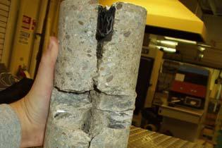


60 APPENDIX C OH 2 Core Photos and 2001/2004 FWD Data C-1
61 Load Transfer Efficiency (%) Joint Joint Joint Joint Joint Joint Steel Fiberglass Stainless Steel Dowel Type Load Transfer Efficiency (%) Joint Joint Joint Joint Joint Joint Steel Fiberglass Stainless Steel Dowel Type C-2
62 APPENDIX D Detailed Project Status Reports (Source: Draft FHWA July 30, 2004 Updated HPCP Summary Report QES 2004) CHAPTER 27. OHIO 1, 2, AND 3 (U.S. Route 50, Athens) Introduction Under the TE-30 program, the Ohio Department of Transportation (ODOT) constructed three experimental pavement projects on U.S. 50, approximately 8 km (5 mi) east of the city of Athens (see figure 45). The projects incorporate a variety of experimental design features, including high-performance concrete mixtures utilizing ground granulated blast furnace slag (GGBFS) (Ohio 1), alternative dowel bar materials (Ohio 2), and alternative joint sealing materials (Ohio 3) (Ioannides et al. 1999; Sargand 2000; Hawkins et al. 2000). Although each project was funded separately under the TE-30 program, they are all located on the same section of roadway and share many of the same design and construction attributes, as well as the same traffic and environmental loadings; therefore, these projects are all described together in this chapter Columbus Athens Ohio 1, 2, and 3 U.S. 50, Athens Figure 45. Location of OH 1, 2, and 3 projects. D-1
63 Study Objectives The study objectives for the overall U.S. 50 pavement project may be broken out by each specific study. For OH 1, the evaluation of GGBFS, the primary objective is to evaluate the effectiveness of GGBFS as a partial cement replacement in PCC pavements. The expectation of adding GGBFS to a concrete mix is increased workability, increased durability, and increased long-term strength. For OH 2, the evaluation of alternative dowel bar materials, the general purposes of the study are to evaluate dowel response under a variety of loading and environmental conditions and to compare the measured responses of different types of dowel bars (Sargand 2000). Specific objectives include the following (Sargand 2000): Instrument standard steel and fiberglass dowels for the monitoring of strain induced by curing, changing environmental conditions, and applied dynamic forces. Record strain measurements periodically over time to determine forces induced in the dowel bars during curing and during changing environmental conditions. Record strain measurements in the dowel bars as dynamic loads are applied with the FWD. Evaluate strain histories recorded for the in-service pavement. For OH 3, the evaluation of joint sealing materials, the objectives are to (Ioannides et al. 1999): Assess the effectiveness of a variety of joint sealing practices employed after the initial sawing of joints, and to examine their repercussions in terms of reduced construction times and life-cycle costs. Identify those materials and procedures that are most cost effective. Determine the effect of joint sealing techniques on pavement performance. Project Design and Layout General Design Information The U.S. 50 project is a 10.5-km (6.5-mi) segment of highway that was reconstructed and expanded to a new four-lane divided facility. The eastbound lanes of the project were constructed in the fall of 1997, and the westbound lanes were constructed in the fall of 1998 (Ioannides et al. 1999). D-2
64 The 20-year design traffic loading for this pavement is approximately 11 million ESAL applications. The subgrade over the project site is predominantly a silty clay material (Ioannides et al. 1999). The cross-sectional design for the projects is a 254-mm (10-in) JRCP placed over a 102-mm (4- in) open-graded base course. The open-graded base course in the eastbound direction is a New Jersey type nonstabilized base, whereas the open-graded base course in the westbound direction is a Iowa type nonstabilized base (Ioannides et al. 1999). A 152-mm (6-in) crushed aggregate subbase is located beneath the open-graded bases, and is topped with a bituminous prime coat to prevent migration of fines into the open-graded layers (Ioannides et al. 1999). Table 21 provides the actual project gradations for these materials. A 102-mm (4-in) underdrain was placed at both the outside and inside edges of the pavement to collect infiltrated moisture from the open-graded bases (Ioannides et al. 1999). Table 21. Comparison of actual base and subbase gradations used on Ohio U.S. 50 project. Total Percent Passing Sieve New Jersey Open- Iowa Open- Crushed Aggregate Size Graded Base (EB) Graded Base (WB) Subbase (EB/WB) 2 in 100 1½ in in 100 # # # # # # # The slabs are reinforced with smooth welded wire fabric (WWF) to control random cracking (Sargand 2000). Wire style designation W8.5 x W4 6x12 was specified, meaning that the longitudinal wires have a cross sectional area of 54.8 mm 2 (0.085 in 2 ) and are spaced 152 mm (6 in) apart, and the transverse wires have a cross-sectional area of 25.8 mm 2 (0.04 in 2 ) and are spaced 305 mm (12 in) apart. This style designation translates to a longitudinal steel content of 0.14 percent. The transverse joints are spaced at fixed 6.4-m (21-ft) intervals and contain 38-mm (1.5-in) diameter, 457-mm (18-in) long, epoxy-coated dowel bars on 305-mm (12-in) centers (Sargand 2000). However, some of the joints within the alternative dowel bar project contain either fiberglass dowels or stainless steel tubes filled with concrete (Sargand 2000). Transverse joints were sealed with a preformed compression sealant except for the joints within the joint sealant project. The longitudinal centerline joint is tied with 16-mm (0.62-in) diameter, 760-mm (30-in) long, deformed bars spaced at 760-mm (30-in) intervals (Ioannides et al. 1999). D-3
65 Plain concrete shoulders were paved separately from the mainline pavement. These were tied to the mainline pavement using 16-mm (0.62-in) diameter, 76-mm (30-in) long, deformed tie bars. The outside shoulder is 3 m (10 ft) wide and the inside shoulder is 1.2 m (4 ft) wide (Ioannides 1999). Project Layout Information As described previously, the U.S. 50 project actually includes three projects, one evaluating GGBFS, one evaluating alternative dowel bar materials, and one evaluating joint sealant materials. In addition, a control section that does not contain GGBFS is located at the western end of the project. The general layout of these projects is shown in figure 46. More detailed information on each project is provided in the following sections. Begin Project STA End Project STA OH 3 Joint Seal Study to OH 3 Joint Seal Study to U.S. 50 WB U.S. 50 EB OH 2 Dowel Bar Study to OH 3 Joint Seal Study to OH 3 Joint Seal Study to OH 1 Control Section (No GGBFS in mix) to OH 1 GGBFS Study to Both Directions Figure 46. Layout of experimental projects on Ohio U.S. 50. OH 1, Evaluation of Ground Granulated Blast Furnace Slag The entire 10.5-km (6.5-mi) length of the U.S. 50 project was constructed using a highperformance concrete mix. The mixture consists of a Type I cement with GGBFS replacing 25 percent of the cement (Sargand 2000). An AASHTO #8 gravel (0.13 mm [0.5 in] top size) was used for the coarse aggregate and a natural sand was used for the fine aggregate (Sargand 2000). A w/c of 0.44 was used in the mix design. The complete PCC mix design is shown in table 22. D-4
66 Table 22. Concrete pavement mix design used on Ohio U.S. 50 project. PCC Mix Design Component Quantity Natural Sand 1437 lb/yd 3 AASHTO #8 Aggregate 1374 lb/yd 3 Type I Cement 412 lb/yd 3 Water 236 lb/yd 3 GGBFS 138 lb/yd 3 Water Reducer 11 oz/yd 3 Air Entraining Agent 16.5 oz/yd 3 Design Air 8% Design Slump 3 in Samples from the concrete mix used in the actual paving operation were tested in the laboratory and showed a 28-day compressive strength of 27.6 MPa (4000 lbf/in 2 ) and a 28-day modulus of rupture of 2.76 MPa (400 lbf/in 2 ) (Sargand 2000). The 28-day static modulus of elasticity was GPa (3,760,000 lbf/in 2 ) (Sargand 2000). As previously mentioned, a control pavement section that does not contain GGBFS in the concrete mix is located at the western end of the project, between stations and Other than the mix design, the design of the control section is the same as the GGBFS section. OH 2, Evaluation of Alternative Dowel Bars Three types of dowel bars were used in the dowel bar project: epoxy-coated steel dowel bars, fiberglass dowel bars (manufactured by RJD Industries, Inc.), and stainless steel tubes filled with concrete. The diameter of the steel and fiberglass dowels bars is 38 mm (1.5 in), while the stainless steel tubes have an outer diameter of 38 mm (1.5 in) and an inner diameter of 34 mm (1.35 in) (Sargand 2000). All bars are 457 mm (18 in) long. Most of the U.S. 50 project contains conventional epoxy-coated steel dowel bars. However, three specific test sections, each incorporating one of the load transfer devices under study, were set up near the western-most limits of the project in the eastbound direction to instrument dowel response and to compare the performance of the different load transfer devices. Each test section is made up of six consecutive joints, with the middle two joints containing instrumented dowel bars (see figure 47). The concrete-filled stainless steel bars were not instrumented because the thin wall thickness did not permit the necessary installation operation to protect the lead wires of the gages (Sargand 2001). Three dowel bars within each joint are instrumented. The instrumented bars are located at distances of 152 mm (6 in), 762 mm (30 in), and 1980 mm (78 in) from the outside edge of the pavement, as shown in figure 48 (Sargand 2000). Each instrumented dowel bar contained a uniaxial strain gauge on the top and the bottom of the bar, and one 45-degree rosette on the side. The uniaxial gauges measure environmental and dynamic strains while the rosette gauges measure only dynamic strains (Sargand 2000). D-5
67 Dowel Test Section (6 joints for each dowel type) Traffic Traffic 21 ft Instrumented Joints Figure 47. Layout of dowel test sections on Ohio U.S. 50 project. Two thermocouple units were also installed near each instrumented joint to measure temperatures in the concrete slab. One unit housed three sensors that measure temperatures at depths of 102, 178, and 254 mm (4, 7, and 10 in) from the surface of the slab, and the second unit consists of a single sensor measuring temperatures at a depth of 25 mm (1 in) below the surface of the slab (Sargand 2000). Traffic Flow Instrumented Dowels 3.66 m (12 ft) Dowel #3 508 mm (20 in) Dowel #3 229 mm (9 in) Dowel #2 Thermocouples 1.37 m (54 in) 1.52 m (60 in) Thermocouples 1.98 m (78 in) Dowel #2 Dowel #1 Dowel #1 762 mm (30 in) 152 mm (6 in) Joint 1 Joint m (21 ft) Figure 48. Dowel instrumentation layout for Ohio U.S. 50 project (Sargand 2000). D-6
68 OH 3, Evaluation of Joint Sealing Materials The joint sealant evaluation is conducted in selected segments of both the eastbound and westbound directions of U.S. 50. A total of nine different joint sealants are evaluated (including four silicone sealants, two hot-poured sealants, and three compression seals), each of which is installed in a unique joint channel configuration. In addition, several pavement sections containing no sealant are included in the study. Table 23 summarizes the location of the different sealant materials in each direction, as well as the joint channel configuration (see figure 49) used for each material (Hawkins, Ioannides, and Minkarah 2000). The westbound sections each represent replicate sealant sections of those in the eastbound lanes, with the exception of the Watson Bowman WB-687 in the eastbound lanes, which was replicated using the Watson Bowman WB-812 in the westbound lanes (Ioannides et al. 1999). The eastbound lanes were sealed in October and November of 1997, whereas the westbound lanes were sealed in December 1998 (silicone and compression seals) and April 1999 (hot-poured sealants) (Ioannides et al. 1999). State Monitoring Activities The Ohio DOT, in conjunction with researchers from several state universities, monitored the performance of these pavements for 5 years. Annual condition surveys and profile measurements were conducted, along with special FWD testing on the instrumented joints. In addition, detailed joint sealant evaluations following SHRP procedures were performed annually on a selected samples of each sealant material. Table 23. Sealant materials used in joint sealant study on Ohio U.S. 50 project (Hawkins, Ioannides, and Minkarah 2000). Sealant Material Eastbound Direction Sealant Type Begin Station End Station Joint Configuration Section Length, ft No. of Joints TechStar W-050 Preformed No Sealant Dow 890-SL Silicone Crafco 444 Hot-Pour Crafco 903-SL Silicone Watson Bowman WB-687 Preformed Crafco 902 Silicone Silicone Crafco 903-SL Silicone Dow 890-SL Silicone No Sealant Delastic V-687 Preformed Crafco 221 Hot-Pour Dow 890-SL Silicone Dow 888 Silicone Dow 888 Silicone D-7
69 Westbound Direction TechStar W-050 Preformed No Sealant Dow 890-SL Silicone Crafco 221 Hot-Pour Crafco 903-SL Silicone Crafco 903-SL Silicone Dow 890-SL Silicone Crafco 444 Hot-Pour Dow 888 Silicone Delastic V-687 Preformed Watson Bowman WB-812 Preformed Dow 888 Silicone Crafco 903-SL Silicone Dow 890-SL Silicone No Sealant / 8 ± 1 / 16 in 1 / 4 ± 1 / 16 in 3 / 8 ± 1 / 16 in 1 / 4-3 / 8 in 1 / 4-3 / 8 in 1 / 4-3 / 8 in 1 / 4-3 / 8 in 1 ½ in 3 ¼ in 3 ¼ in 1 in 1 ½ in 3 ¼ in Compression Seal ½ in Backer Rod 5 / 16 in Backer Rod 1 / 8 in 1 / 8 in 1 / 8 in Detail 1 Detail 3 Detail 5 1 / 8 ± 1 / 16 in 1 / 8 ± 1 / 16 in 1 / 4-3 / 8 in 3 / 16-5 / 16 in 1 / 4 ± 1 / 16 in 3 ¼ in 3 ¼ in ¼ in Backer Rod 3 ¼ in Detail 2 Detail 4 Detail 6 Figure 49. Joint channel configurations used in sealant study on Ohio U.S. 50 project (Hawkins, Ioannides, and Minkarah 2000). D-8
70 Results/Findings Performance results are available in the final reports for these sections. This information is presented in the following sections for each specific study. OH 1, Evaluation of Ground Granulated Blast Furnace Slag The final report, Application of High Performance Concrete in the Pavement System, Structural Response of High Performance Pavements, March 2002 provides the results from this study. Several factors related to the performance of the HPC pavement containing 25 percent GGBFS have been evaluated with the following results. Temperature gradients generated between the top and bottom of concrete slabs during the cure period can have a significant impact on the development of early cracks. HPC pavement sections placed in October, 1997 experienced gradients of 10 degrees C, and developed cracking within eighteen hours of placement. One HPC and one standard pavement section placed in October, 1998 experienced gradients of only 5 degrees C, and did not develop cracking. The higher temperature gradient in 1997 resulted from a cold front shortly after placement. Large values of strain recorded with the vibrating wire strain gages and maturity measurements indicated that the HP 1 and HP 2 sections could be expected to crack, as was observed in the field. HP 3 constructed one year later of the same concrete mix but during a period of warmer weather did not develop cracks. In this case, both strain and maturity data collected in the field indicated a low probability of cracking. Results from HIPERPAV also suggested that sections HP 1 and HP 2 would crack, while HP 3 would not. Predicted strength curves were calculated for the placements, in addition to those provided by the standard HIPERPAV prediction model. Section HP 3 had less initial warping than did section SP (standard ODOT paving concrete). Sections HP 1 and 2 developed cracking, precluding effective curling measurement of these slabs. Based on the laboratory results and field data obtained in this study, the following conclusions were derived (Sargand 2002): Temperature gradients generated between the surface and bottom of concrete slabs during the curing process can have a significant impact on the formation of early cracks. Section HP3 had less initial warping than did section SP constructed with standard ODOT class C concrete. FWD data indicated that, under similar loading conditions, the HP3 section experienced slightly less deflection at joints than the SP section. With limited data available, it was suggested that the moisture in the base at sealed and unsealed joints was similar. In some cases, however, moisture under sealed conditions D-9
71 was observed to be slightly higher, indicating that joint seals might trap moisture under the pavement. During FWD tests the deflection at sealed joints was generally higher than at unsealed joints. OH 2, Evaluation of Alternative Dowel Bars An analysis of the strains in both the fiberglass and steel dowel bars under environmental and dynamic loading was conducted (ORITE 1998; Sargand 2000; Sargand 2001). Major findings from that analysis include (Sargand 2000; Sargand 2001): In addition to transferring dynamic load across PCC pavement joints, dowel bars serve as a mechanism to reduce the curling and warping of slabs due to curing and temperature and moisture gradients in the slabs. Steel and fiberglass dowels both experienced higher moments from environmental factors than from dynamic loading. The dynamic bending stresses induced by a 56.9 kn (12,800 lb) load were considerably less than the environmental bending stresses induced by a 3 o C (5.4 o F) temperature gradient. Steel bars induced greater environmental bending moments than fiberglass bars. Significant stresses were induced by steel dowel bars early in the life of this pavement as it cured late in the construction season under minimal temperature and thermal gradients in the slab. Concrete pavements paved in the summer under more severe conditions may reveal even larger environmental stresses. Both types of dowels induced a permanent bending moment in the PCC slabs during curing, the magnitude of which is a function of bar stiffness. Curling and warping during the first few days after concrete placement can result in large bearing stresses being applied to the concrete around the dowels. This stress may exceed the strength of the concrete at that early age and result in some permanent loss of contact around the bars. Steel bars transferred greater dynamic bending moments and vertical shear stresses across transverse joints than fiberglass bars of the same size. Given these findings, it is concluded that the effects of environmental cycling and dynamic loading both must be included in the design and evaluation of PCC pavement joints (Sargand 2001). Because of the high bearing stresses that can be generated in concrete surrounding dowel bars, this parameter should be considered in dowel bar design, especially during the first few days after placement of concrete (Sargand 2001). D-10
72 It is noted that these results are based on the analysis of the instrumented steel and fiberglass dowel bars only. The stainless steel tubes were not instrumented for the reason stated earlier. OH 3, Evaluation of Joint Sealing Materials The results from this experiment, through the 2001 performance evaluation have resulted in several observations (Ioannides et al. 1999; Hawkins, Ioannides, and Minkarah 2000): The silicone and hot-poured sealants in the eastbound lanes are in fair to poor condition, typically suffering from full-depth adhesion failure. The worst of the sealed sections were those with a narrow joint width of 3 mm (0.12 in). In these installations, the sealant material had overflowed and run onto the pavement surface. There is a significant difference in the performance of the same joint seal materials from EB (constructed in '97) and WB (constructed in '98). This difference is attributed to improvements in installation temperatures, experience, and equipment. The joints in this experiment were cleaned only by water- and air-blasting, even when the sealant manufacturers recommended sand blasting. This suggests that some of the adhesion loss may be due to an inadequate cleaning process. Both the Watson Bowman and the Delastic compression seals have performed by far best overall in both directions. In the WB direction, the silicones have performed best, but were poor in the EB. The performance of the hot pour materials is very different, being far better in WB in general. However, the Crafco 221 material did relatively well in one EB test section. The TechStar compression seal, however, has developed significant adhesion failure and has sunk into the joint. The compression seals have performed by far best overall in both directions. In the WB direction, the silicones have performed best, but were poor in the EB. The performance of the hot pour materials is very different, being far better in WB in general. However, the Crafco 221 material did relatively well in one EB test section. Hot pour material appears to have performed better when installed within the manufacturer's recommended temperature range. No specific temperature range is recommended for the silicone materials. Roughness measurements made using PSI, IRI, and Mays meter do not provide any conclusive trends relating to pavement performance. Assessment of joint seal efficiency has little relationship to pavement condition, at this time. It is recommended to reseal the EB sites, except for the two compression seals for continued performance monitoring. D-11
73 The Techstar W-050 material performed poorly in both directions, and is considered unsuitable for pavement applications. Currently, the unsealed sections seem to have more spalling, corner, and midslab cracking distress than others, although there is no conclusive pavement performance related trends as yet. A summary of estimated joint sealant costs on this project is provided in table 24 (Ioannides et al. 1999). These costs are based solely on the material costs themselves and do not include the costs of backer rods, adhesives, or labor. Table 24. Summary of sealant costs on Ohio U.S. 50 project (Ioannides et al. 1999). Material Unit Cost Estimated Cost/Joint Dow 890-SL $48.00/gal $12.27 Crafco 903-SL $36.00/gal $9.50 Dow 888 $42.00/gal $10.74 Crafco 902 $39.00/gal $9.97 Crafco 444 $10.50/gal $2.68 Crafco 221 $0.25/lb $0.64 Watson Bowman WB-812 $1.03/ft $43.26 Watson Bowman WB-687 $0.72/ft $30.24 Delastic V-687 $0.66/ft $27.72 TechStar V-050 $8.65/ft $ Points of Contact Shad Sargand Ohio University Ohio Research Institute for Transportation and the Environment Department of Civil and Environmental Engineering Stocker Center Athens, OH (740) Anastasios Ioannides Department of Civil and Environmental Engineering 741 Baldwin Hall (ML-0071) University of Cincinnati P.O. Box Cincinnati, OH (513) Roger Green Ohio Department of Transportation Office of Pavement Engineering 1980 West Broad Street Columbus, OH (614) D-12
74 References Hawkins, B. K., A. M. Ioannides, and I. A. Minkarah To Seal or Not to Seal: Construction of a Field Experiment to Resolve an Age-Old Dilemma. Preprint Paper No th Annual Meeting of the Transportation Research Board, Washington, DC. Ioannides, A. M., I. A. Minkarah, B. K. Hawkins, and J. Sander Ohio Route 50 Joint Sealant Experiment Construction Report (Phases 1 and 2) and Performance to Date ( ). Ohio Department of Transportation, Columbus, OH. Ohio Research Institute for Transportation and the Environment (ORITE) Measurement of Dowel Bar Response in Rigid Pavement. ORITE-1. Ohio Department of Transportation, Columbus, OH. Sargand, S. M Performance of Dowel Bars and Rigid Pavement. Draft Final Report. Ohio Department of Transportation, Columbus, OH. Sargand, S.M., Edwards, W., Khoury, I Ohio Research Institute for Transportation and the Environment (ORITE). Application of High Performance Concrete in the Pavement System, Structural Response of High Performance Concrete Pavement. Final Report Sargand, S.M Performance of Dowel Bars and Rigid Pavement. Final Report. Ohio Research Institute for Transportation and the Environment (ORITE), Athens, Ohio. D-13
75 CHAPTER 11. IOWA 2 (U.S. Route 65, Des Moines) Introduction The Iowa Department of Transportation s second TE-30 project consists of an evaluation of alternative dowel bar materials and spacings. The experimental project was constructed in 1997 on the U.S. 65 Bypass near Des Moines (Cable and McDaniel 1998b). Figure 17 shows the location of this project. 35 Des Moines Iowa 2 U.S. 65 Bypass, Des Moines Figure 17. Location of IA 2 project. Study Objectives Because of the susceptibility of steel dowel bars to corrosion, the Iowa DOT has expressed interest in the use of alternative dowel bar materials to provide load transfer across transverse joints in concrete pavements. Therefore, one of the goals of this project is the comparative study of concrete pavement joints containing fiber reinforced polymer (FRP) dowel bars, stainless steel dowel bars, and conventional epoxy-coated steel dowel bars under the same design criteria and field conditions (Cable and McDaniel 1998b). Another goal of the project is the investigation of the transverse joint load transfer characteristics of alternative dowel bar spacings (Cable and McDaniel 1998b). This evaluation is a 5-year study being performed through the combined efforts of the Iowa Department of Transportation and the Iowa State University. D-14
76 Project Design and Layout This project was constructed in 1997 on the northbound lanes of the U.S. 65 Bypass near Des Moines. The basic design for the project is a 305-mm (12-in) JPCP on a 152-mm (6-in) granular base course (Cable and McDaniel 1998b). Transverse joints are located at 6.1-m (20-ft) intervals and are skewed 6:1 in the counterclockwise direction (Cable and McDaniel 1998b). Both transverse and longitudinal joints are sealed with a hot-poured sealant. Number 5 tie bars, 914 mm (36 in) long and spaced at 762-mm (30-in) intervals, were mechanically inserted by the paver across the longitudinal centerline joint (Cable and McDaniel 1998b). The shoulder for the JPCP is a 203-mm (8-in) asphalt concrete (AC) layer, paved 2.4 m (8 ft) wide on the outside edge and 1.6 m (6 ft) on the inside edge (Cable and McDaniel 1998b). Longitudinal subdrains are located under the outside shoulder and adjacent to the edge of the outside driving lane (Cable and McDaniel 1998b). Four different load transfer systems are included in the study: a fiber composite dowel bar manufactured by Hughes Brothers, a fiber composite dowel bar manufactured by RJD Industries, a Type 316L solid stainless steel dowel bar, and a conventional epoxy-coated steel dowel bar (Cable and McDaniel 1998b). The Hughes Brothers dowel bar is 48 mm (1.88 in) in diameter, whereas the other dowel bars are 38 mm (1.5 in) in diameter. The required diameters for the alternative dowel bars were determined from laboratory testing and experimental research performed by the manufacturers (Cable and McDaniel 1998b). A standard spacing of 305 mm (12 in) was used for each load transfer system included in the study. In addition, sections were constructed using a spacing of 203 mm (8 in) for the alternative dowel bar materials. The experimental design matrix for this project is shown in table 9, and the layout of the test sections is shown in figure 18. The dowel bar spacing configurations used on this project are illustrated in figure 19. Table 9. Experimental design matrix for IA mm (12-in) JPCP 6.1-m (20-ft) Joint Spacing (skewed) Fiber Composite Dowel Bars (Hughes Brothers) Fiber Composite Dowel Bars (RJD Industries) Stainless Steel Dowel Bars Epoxy-Coated Steel Dowel Bars 38-mm (1.5-in) Diameter Dowel Section 3 (100 ft) Section 5 (222 ft) 203-mm (8-in) Dowel Spacing 48-mm (1.88-in) Diameter Dowel Section 1 (440 ft) 38-mm (1.5-in) Diameter Dowel Section 4 (80 ft) Section 6 (556 ft) Section 8 (477 ft) 305-mm (12-in) Dowel Spacing 48-mm (1.88-in) Diameter Dowel Section 2 (417 ft) D-15
77 Section in Fiber Composite Dowel Bars (RJD Industries) 8 in Dowel Spacing Section in Fiber Composite Dowel Bars (RJD Industries) 12 in Dowel Spacing U.S. 65 NB Section in Fiber Composite Dowel Bars (Hughes Brothers) 8 in Dowel Spacing Section in Fiber Composite Dowel Bars (Hughes Brothers) 12 in Dowel Spacing Section in Stainless Steel Dowel Bars 8 in Dowel Spacing Section in Stainless Steel Dowel Bars 12 in Dowel Spacing Section in Epoxy-Coated Steel Dowel Bars 12 in Dowel Spacing 440 ft 417 ft 100 ft 80 ft 222 ft 556 ft 477 ft Figure 18. Layout of IA 2 project. Outer Traffic Lane Inner Traffic Lane in spacings in spacings a) 12-in Spacings Inner Traffic Lane Outer Traffic Lane 18 8-in spacings 18 8-in spacings b) 8-in Spacings Figure 19. Illustration of dowel bar spacing configurations on IA 2. D-16
78 Fiber composite tie bars were also provided by the fiber composite dowel bar manufacturers for installation in their respective test sections. However, these fiber composite tie bars had a tendency to float to the top of the surface during or immediately after their placement (Cable and McDaniel 1998b). This was attributed to either an incompatibility of the automatic tie bar inserter to the smaller diameter of the fiber composite tie bars or to the lighter weight of the fiber composite bars themselves (Cable and McDaniel 1998b). After several bars surfaced in succession, the epoxy-coated steel tie bars were used on the remainder of the project. State Monitoring Activities The performance of these test sections was monitored under a 5-year monitoring program (from the Fall of 1997 through the Spring of 2003) being conducted jointly by the Iowa DOT and the Iowa State University (Cable and Porter 2003). The following monitoring activities were conducted (Cable and Porter 2003): Visual distress survey using LTPP procedures. As part of these surveys, joint openings were monitored using PK nails placed along joints in each section, and joint faulting was measured using a Georgia Digital Faultmeter. Deflection testing using a Dynatest Falling Weight Deflectometer (FWD). Within each section, deflection testing was performed at three joints and at three center slab locations per lane. Testing was performed twice a year, once in March or April (to represent a weak foundation condition) and once in August or September (to represent a strong foundation condition). In addition, ground penetrating radar (GPR) was used to establish the location (depth and orientation) of dowel bars and tie bars (Cable and Porter 2003). At the end of 5 years, selected joints in each section were cored and the condition of each dowel bar type was inspected (Cable and Porter 2003). Preliminary Results/Findings During the construction of the project, several items were noted to be of importance to future installations of alternative dowel bars in concrete pavements (Cable and McDaniel 1998b): The original method of securing the fiber composite and stainless steel dowel bars to the basket was inadequate. To address this, plastic zip ties were fastened around each basket brace loop and end of dowel to hold them in place. Any excess tie length was cut or turned down to prevent surface finishing problems. The placement of the stainless steel dowels required three to five people to handle the baskets. Future use of stainless steel dowels will require x braces welded to the basket to prevent side sway and collapse during handling. D-17
79 Nails were attached to the bottom of the fiber composite tie bars to facilitate their location using both cover meters and GPR. As stated previously, the fiber composite tie bars, placed using the automatic tie bar inserter on the paver, were susceptible to floating to the surface. If this is a continuing problem, the placement of these bars in tie bar baskets or the use of conventional epoxycoated tie bars may be required. Final Results/Findings Project test sections were tested twice a year, beginning in the Fall of 1997, with the final tests in the Spring of Testing could not be performed in the fall of The results of the FWD testing were interpreted through calculating load transfer efficiency. The results of the load transfer analysis are illustrated in figure 20 (Cable and Porter 2003). In figure 20, the dowel bars are labeled according to their material and spacing: standard epoxy (std. epoxy), stainless steel (S.S.), fiber composite (FRP). Figure 21 displays the overall average faulting over the period of research (Cable and Porter 2003). Figure 22 illustrates the changes in joint openings over the research period (Cable and Porter 2003). Visual surveys of this project resulted in only minor corner cracking being noted immediately after construction. There are no visible signs of pavement distress that can be associated with joint reinforcement or typical highway loading over the five years of surveys (Cable and Porter 2003). The following summaries and conclusions have been reached based on the data gathered during the study (Cable and Porter 2003): All dowel materials tested are performing equally in terms of load transfer, joint movement, and faulting over the five-year analysis period. Stainless steel dowels do provide load transfer performance equal to or greater than epoxy-coated steel dowels in this study on the average over five years. FRP dowels of the sizes tested in this research should be spaced no greater than 8 inches (203 mm) apart to gain load transfer performance at the same level as epoxy-coated steel dowels at 12-inch (305 mm) spacing. No deterioration due to road deicers was found on any of the dowel materials retrieved in the 2002 coring operation. D-18
80 Std. Epoxy 8" 94 Dowel Type & Scheme " 12" " 8" " 12" " 8" 80 Passing Driving Driving Passing Figure 20. Average Load Transfer Efficiency 0 Epoxy@12" S.S.@12" 8" 1.5" 12 " 1.5" 8" " 12" " 8" Ave. Fault, in Outside Wheelpath Ave. Inside Wheelpath Ave. Average Figure 21. Average Faulting Over Research Period D-19
81 Joint Opening Change (mm) Fall 1997 Spring 1998 Fall 1998 Spring 1999 Fall 1999 Spring 2000 Data Collection Period Spring Fall 2001 Spring 2002 Figure 22. Joint Opening Trends Points of Contact Jim Cable Iowa State University Department of Civil and Construction Engineering 378 Town Engineering Building Ames, IA (515) Mark Dunn Iowa Department of Transportation 800 Lincoln Way Ames, IA (515) Reference Cable, J. K. and L. L. McDaniel. 1998b. Demonstration and Field Evaluation of Alternative Portland Cement Concrete Pavement Reinforcement Materials. Iowa DOT Project HR Iowa Department of Transportation, Ames, IA. D-20
82 Cable, J. K. and M.L.Porter Demonstration and Field Evaluation of Alternative Portland Cement Concrete Pavement Reinforcement Materials. Iowa DOT Project HR Iowa State University, Ames, IA. D-21
83 CHAPTER 36. WISCONSIN 2 (Highway 29, Owen) AND WISCONSIN 3 (Highway 29, Hatley) Introduction In the summer of 1997, WisDOT constructed two experimental concrete pavement projects on Highway 29 to investigate the constructibility and cost effectiveness of alternative concrete pavement designs (Crovetti 1999; Crovetti and Bischoff 2001). Constructed with partial funding from the TE-30 program, one project (designated WI 2) is located in the eastbound lanes of Highway 29 between Owen and Abbotsford, while the other project (designated WI 3) is located in both lanes of Highway 29 between Hatley and Wittenberg (see figure 60). The WI 3 test sections are also part of FHWA s ongoing Strategic Highway Research Program (SHRP) study. Because of the similarities and complementary design of these two projects, they are considered together in this chapter. Wisconsin 2 Highway 29 EB, Owen to Abbotsford Wisconsin 3 Highway 29, Hatley to Wittenberg 94 Owen 29 Abbotsford Wittenberg Hatley 39 Madison 94 Milwaukee Figure 60. Location of WI 2 and WI 3 projects. D-22
84 Study Objectives The overall objective of these projects is to evaluate the constructibility and cost-effectiveness of alternative concrete pavement designs (Crovetti 1999). Among the different concrete pavement designs and design features being investigated in these projects are (Crovetti 1999): Reduced number of dowel bar across transverse joints. Alternative dowel bar materials for transverse joint load transfer. Variable thickness pavement cross section. Project Design and Layout Wisconsin 2 The WI 2 project is located only in the eastbound lanes of Highway 29. It was constructed in September 1997 and includes both alternative dowel bar materials and alternative dowel bar layouts (Crovetti 1999; Crovetti and Bischoff 2001): Alternative Dowel Bar Materials Standard epoxy-coated steel dowel bars. Solid stainless steel dowel bars, manufactured by Avesta Sheffield. Fiber-reinforced polymer (FRP) composite dowel bars, manufactured by Glasforms. FRP composite dowel bars, manufactured by Creative Pultrusions. FRP composite dowel bars, manufactured by RJD Industries. Stainless steel tubes filled with mortar, manufactured by Damascus Bishop. Alternative Dowel Bar Layouts Standard dowel layout (dowels spaced at 305-mm [12-in] intervals). Alternative dowel layout 1 (three dowels in each wheelpath). Alternative dowel layout 2 (four dowels in outer wheelpath, three in all other wheelpaths). Alternative dowel layout 3 (four dowels in outer wheelpath, three in all other wheelpaths, one dowel at outer edge). Alternative dowel layout 4 (three dowels in all wheelpaths, one dowel near outer edge). The alternative dowel bar layouts are illustrated in figure 61. These layouts were selected to reduce dowel bar requirements while still maintaining standard placement locations used in Wisconsin (Crovetti 2001). The nominal pavement design for these pavement sections is a 275-mm (11-in) JPCP with skewed variable joint spacing of m ( ft) (Crovetti 1999). The dowel bars were 38 mm (1.5 in) in diameter and were placed using an automated dowel bar inserter (DBI). The transverse joints were left unsealed. The pavement was constructed over existing base materials that were salvaged from the in-place structure, including 230 mm (9 in) of existing dense-graded, crushed aggregate subbase and 125 D-23
85 mm (5 in) of existing dense-graded, crushed aggregate base. An additional 50 mm (2 in) of new dense-graded aggregate base was placed prior to the PCC paving. Figure 62 shows the approximate layout of the eleven test and two control sections included in the WI 2 project, using the section nomenclature adopted by the researchers. Nominal 161-m (528-ft) long pavement segments generally consisting of twenty-nine joints were selected from within each test section for long term monitoring (Crovetti 1999). Table 30 provides the experimental design matrix for the project. 12 ft Inner Lane 14 ft Outer Lane Standard Dowel Layout (26 dowels at 12-in spacings) Alternative Dowel Layout 1 (3 dowels per wheelpath) Alternative Dowel Layout 2 (4 dowels in outer wheelpath, 3 dowels in all other wheelpaths) Alternative Dowel Layout 3 (4 dowels in outer wheelpath, 3 dowels in all other wheelpaths, 1 dowel at outer edge) Alternative Dowel Layout 4 (3 dowels in all wheelpaths, 1 dowel near outer edge) Figure 61. Alternative dowel bar layouts used on WI 2. D-24
86 Section CP Section 4E 11-in JPCP Transition 11-in JPCP FRP Composite Bars 11-in JPCP Steel Dowels (Creative Pultrusions) Steel Dowels Dowel Layout 4 Standard Dowel Layout Standard Dowel Layout Section RJD 11-in JPCP Section 3S FRP Composite Bars 11-in JPCP (RJD Industries) Stainless Steel Dowels Standard Dowel Layout Dowel Layout 3 Section 2E 11-in JPCP Steel Dowels Dowel Layout 2 Section C2 11-in JPCP Steel Dowels Standard Dowel Layout 12 ft 14 ft Traffic 18,785 ft 1612 ft 1555 ft 1651 ft ft 1561 ft 6242 ft 5340 ft 4218 ft 5268 ft 6504 ft Section GF 11-in JPCP FRP Composite Bars (Glasforms) Standard Dowel Layout Section 4S 11-in JPCP Stainless Steel Dowels Dowel Layout 4 Section 3Eb 11-in JPCP Steel Dowels Dowel Layout 3 Section 1E 11-in JPCP Steel Dowels Dowel Layout 1 Section C1 11-in JPCP Steel Dowels Standard Dowel Layout Section HF Section 3Ea 11-in JPCP 11-in JPCP Stainless Steel Tubes Steel Dowels Filled with Mortar Dowel Layout 3 (Damascus-Bishop) Standard Dowel Layout Figure 62. Approximate layout of WI 2 test sections. Table 30. Experimental design matrix for WI 2. Standard Epoxy-Coated Steel Dowels Solid Stainless Steel Dowels (Avesta Sheffield) FRP Composite Dowel Bars (Creative Pultrusions) FRP Composite Dowel Bars (Glasforms) FRP Composite Dowel Bars (RJD Industries) Stainless Steel Tubes Filled with Mortar (Damascus-Bishop) Standard Dowel Layout Section C1 Section C2 Section CP Section GF Section RJD Section HF 11 in JPCP ft Joint Spacing Alternative Alternative Alternative Dowel Layout 1 Dowel Layout 2 Dowel Layout 3 Section 1E Section 2E Section 3Ea Section 3Eb Section 3S Alternative Dowel Layout 4 Section 4E Section 4S Wisconsin 3 The westbound lanes of the WI 3 project were constructed in June 1997, whereas the eastbound lanes were constructed in October 1997 (Crovetti 1999). The project includes the evaluation of a variable thickness cross section, an alternative dowel bar layout, and alternative dowel bar D-25
87 materials. The variable thickness cross section uses a 275 mm (11 in) thickness at the outside edge of the outer lane that then tapers to a thickness of 200 mm (8 in) at the far edge of the inner lane (see figure 63). The goal is the more efficient use of materials in areas subjected to greater traffic loading, resulting in more cost-effective designs. 14 ft Outside Widened Slab 12 ft Inner Lane 12 ft Outer Lane Paint Stripe for 12 ft Lane 8 in Deformed Tie Bar PCC Slab 11 in Base Figure 63. Variable cross section used on WI 3. The following alternative dowel bar materials are also included on the WI 3 project (Crovetti 1999): Standard epoxy-coated dowel bars. FRP composite dowel bars, manufactured by MMFG. FRP composite dowel bars, manufactured by Glasforms. FRP composite dowel bars, manufactured by Creative Pultrusions. FRP composite dowel bars, manufactured by RJD Industries. Solid stainless steel dowel bars, manufactured by Slater Steels. The nominal pavement design for these pavement sections is a 275-mm (11-in) JPCP with a uniform joint spacing of 5.5 m (18 ft). However, as previously described, one section has a variable thickness cross section, varying from 275 mm (11 in) for the outer lane, and then tapering to 203 mm (8 in) at the edge of the inner lane. The pavement rests on a 150-mm (6-in) crushed aggregate base course, and the transverse joints contain 38-mm (1.5-in) diameter dowels and are not sealed. A total of six sections are included in the WI 3 project. The approximate layout of the WI 3 sections being monitored is shown in figure 64. All dowel bars were placed on baskets prior to paving (Crovetti 2001). It is noted that within the section incorporating various FRP composite dowel bars (Section FR), some of the composite dowel bars were improperly distributed between the 3.7-m (12-ft) and 4.3-m (14-ft) baskets, resulting in different manufacturers bars being placed across some of the inner and outer traffic lanes (Crovetti 1999). The location of the different manufacturers dowel bars is shown by lane in the blowup illustration in figure 64. D-26
88 Section TR 8-11 in JPCP Steel Dowels Standard Dowel Layout Section C1 11 in JPCP Steel Dowels Standard Dowel Layout Section 1E 11 in JPCP Steel Dowels Dowel Layout 1 WB Traffic 14 ft 12 ft 12 ft 14 ft EB Traffic Section RJD 11 in JPCP FRP Composite Dowels (RJD Industries) Standard Dowel Layout Section FR 11 in JPCP FRP Composite Dowels (Glasforms, Creative Pultrusions, MMFG) Standard Dowel Layout Section SS 11 in JPCP Solid Stainless Steel Dowels Standard Dowel Layout Inner Lane MMFG + Glas MMFG Glas Glas CP Outer Lane MMFG MMFG MMFG CP CP 1 Joint 1 Joint 252 ft 180 ft 108 ft Figure 64. Approximate layout of WI 3 monitoring sections. The experimental design matrix for the WI 3 project is shown in table 31. Most of the dowel materials are placed in the standard dowel layout, although one section is placed in alternative dowel layout 1. As previously mentioned, all of these sections are included in the SHRP study, and the SHRP code is provided in table 31 for each section. D-27
89 Table 31. Experimental design matrix for WI 3. Standard Epoxy-Coated Steel Dowels Solid Stainless Steel Dowels (Slater Steels) FRP Composite Bars (MMFG, Glasforms, Creative Pultrusions) FRP Composite Dowel Bars (RJD Industries) Standard Dowel Layout Section C1 (SHRP ) Section SS (SHRP ) Section FR (SHRP A) Section RJD (SHRP B) 11-in JPCP 18-ft Joint Spacing Alternative Dowel Layout 1 Section 1E (SHRP ) 8- to 11-in JPCP 18-ft Joint Spacing Standard Dowel Layout Section TR (SHRP ) State Monitoring Activities WisDOT, in conjunction with Marquette University, is monitoring the performance of these pavement test sections. These monitoring activities include (Crovetti 1999; Crovetti and Bischoff 2001): Dowel bar location study conducted 2 months after construction. FWD testing conducted immediately prior to paving, immediately after paving, and after 6 and 12 months of trafficking. Distress surveys conducted immediately after paving and after 6 and 12 months of trafficking. The distress surveys are being conducted over a nominal 161-m (528-ft) pavement segment selected from within each test section. Ride quality surveys conducted using a pavement profiler and measured on the sections after approximately 1 and 3 years of service. Continued monitoring of these sections, in the form of FWD testing, distress surveys, and ride quality surveys, will continue through 2004 (Crovetti and Bischoff 2001). Preliminary Results/Findings Even though these sections are only 3 years old, some significant findings have been revealed through their early monitoring. These findings are described in the following sections by type of monitoring activity. Construction Monitoring D-28
90 A dowel bar inserter (DBI) was used during the construction of WI 2. The DBI easily accommodated the various types of dowel bar materials used in the study, and the DBI also accommodated the various dowel layout patterns with minimal disruption to the paving operations (Crovetti 1999). Dowel Bar Location Study With the purpose of determining the depth, longitudinal position, and transverse position of each dowel bar, a dowel bar location study was performed on the WI 2 project 2 months after construction using an impact echo device (Crovetti 1999). A summary of the results from the study are provided in table 32 (Crovetti 1999). Generally, it appears that the dowel bars are slightly deeper than the mid-depth of the slab (140 mm [5.5 in]), and that some vertical skewing of the dowels occurred across the joint. It should be noted that dowel depth data were inconclusive for the stainless steel tubes and the solid stainless steel dowels, and that the device could not provide exact longitudinal and transverse positions of each dowel end (Crovetti 1999). Table 32. Summary of dowel bar location study results from WI 2 (Crovetti 1999). Test Section No. of Joints Tested Average Depth, West Side of Joint, in Average Depth, East Side of Joint, in Average Depth Variation, in C1 (epoxy-coated steel dowel) CP (FRP composite dowel) GF (FRP composite dowel) RJD (FRP composite dowel) FWD Testing FWD testing has been conducted several times since the construction of these test sections. Table 33 summarizes the backcalculated k-value and concrete elastic modulus, as well as the total joint deflection (defined as the sum of the deflections from both the loaded and unloaded sides of the joint) obtained from the FWD testing (Crovetti 1999). Generally, the test results are fairly consistent over time, although greater variability was noticed in the June 1998 tests for both directions, presumably because of higher slab temperature gradients (Crovetti 1999). Apparent increases in total joint deflections may be due to FWD testing conducted in the early morning when upward slab curling is likely. D-29
91 Table 33. Summary of FWD test results for WI 2 and WI 3 projects (Crovetti 1999). WI 2 WI 3 Property EB lanes EB lanes WB lanes Oct 97 Jun 98 Nov 98 Oct 97 Jun 98 Nov 98 Jun 98 Nov 98 Dynamic k-value, lbf/in 2 /in PCC Elastic Modulus, lbf/in 2 3,560,000 3,870,000 4,820,000 3,970,000 5,990,000 6,060,000 5,290,000 6,130,000 Total 9000-lb Joint Deflection, mils Transverse joint load transfer efficiencies were also measured on all test sections using the FWD. Figure 65 illustrates the average transverse joint load transfer for the outermost wheelpath of the WI 2 project, while figure 66 illustrates the average transverse joint load transfer for the outermost wheelpath of the WI 3 project (Crovetti 1999). For WI 2, the late season tests (October 1997 and November 1998) indicate significantly reduced LTE in the composite doweled sections and in dowel layout 1 as compared to the control sections (Crovetti 1999). However, LTE measured in the summer do not indicate any significant differences within the test sections, probably because of the increased aggregate interlock brought about by the closing of the joints due to the warmer temperatures (Crovetti 1999). For WI 3, figure 66 shows that the FRP composite dowel sections and dowel layout 1 experience a reduction in LTE in the November 1998 test results; there is also a slight reduction in the LTE of the stainless steel section (Crovetti 1999). However, LTE measured in June 1998 do not indicate any significant differences between the test sections. Distress Surveys Distress surveys were conducted for both WI 2 and WI 3 in June and December Some joint distress (spalling, chipping, and fraying of the transverse joints) was observed and is primarily attributable to the joint sawing operations that dislodged aggregate particles near the joint faces (Crovetti and Bischoff 2001). However, this joint spalling has not yet progressed to the point to be considered as low severity based on the Wisconsin DOT Pavement Distress guidelines (Crovetti and Bischoff 2001). Other than the minor joint spalling, no transverse faulting, slab cracking, or other surface distress has been observed to date (Crovetti and Bischoff 2001). Ride Quality Surveys Figure 67 presents the average international roughness index (IRI) measurements in the outer lane of the WI 2 and WI 3 pavement sections (Crovetti and Bischoff 2001). These measurements were recorded in the summer of 1998 and the winter of Although there is D-30
92 some variability in the data, most of the test sections are performing comparably to the control sections (Crovetti and Bischoff 2001). Points of Contact James A. Crovetti Marquette University Department of Civil and Environmental Engineering P.O. Box 1881 Milwaukee, WI (414) Debbie Bischoff Wisconsin Department of Transportation 3502 Kinsman Boulevard Madison, WI (608) Load Transfer Efficiency, % C 1 C P G F RJ D H F 3 S 4 S 4 E 3 E 2 E 1 E C 2 Test Section Oct 97 Jun 98 Nov 98 Figure 65. Transverse joint load transfer for outermost wheelpath on WI 2 (Crovetti 1999). D-31
93 Load Transfer Efficiency, % RJD FR SS 1E C1 TR Test Section Oct 97 Jun 98 Nov 98 Figure 66. Transverse joint load transfer for outermost wheelpath on WI 3 (Crovetti 1999) IRI, in/mi C1 1E 2E 3Ea 4E 4S 3S 3Eb HF RJD GF CP C2 1E FR RJD SS TR C1 Wisconsin 2 Sections Wisconsin 3 Sections Figure 67. Average IRI values in the outer traffic lanes of WI 2 and WI 3 pavement sections (Crovetti and Bischoff 2001). D-32
94 References Crovetti, J. A Cost Effective Concrete Pavement Cross-Sections. Report No. WI/SPR Wisconsin Department of Transportation, Madison, WI. Crovetti, J. A. and D. Bischoff Construction and Performance of Alternative Concrete Pavement Designs in Wisconsin. Preprint Paper No th Annual Meeting of the Transportation Research Board, Washington, DC. D-33
95 CHAPTER 5. ILLINOIS 1 (I-55 SB, Williamsville) Introduction This project was the first constructed by the Illinois Department of Transportation (IDOT) to evaluate alternative dowel bars for use in jointed concrete pavements. Constructed in 1996, the project is located on the exit ramp of a weigh station in the southbound direction of I-55 (milepost 107) near Williamsville, just north of Springfield (see figure 2). Although not a TE-30 project, it did serve as a springboard for future IDOT projects evaluating alternative dowel bars under the TE-30 program Williamsville Springfield 55 Illinois 1 I-55 SB, Williamsville Figure 2. Location of IL 1 project. Study Objectives On most concrete pavements, steel dowel bars are used at transverse joints to provide positive load transfer between adjacent slabs. However, even if epoxy coated, these dowel bars are susceptible to corrosion, which can create locked or frozen joints that can spall and crack the concrete, significantly reducing the service life of the pavement. The purpose of this study, therefore, is to compare the performance of non-corrosive type E fiberglass and polyester dowels to the performance of conventional epoxy-coated dowel bars in a side-by-side field evaluation project. D-34
96 Project Design and Layout This project was constructed in 1996 and consists of a 280-mm (11.25-in) slab placed on a 100- mm (4-in) bituminous aggregate subbase (BAM) (Gawedzinski 2000). In accordance with IDOT practices at the time, the jointed concrete pavement was constructed as a hinge-joint design, in which conventional doweled transverse joints are spaced at 13.7-m (45-ft) intervals and intermediate hinge joints containing tie bars are placed at 4.6-m (15-ft) intervals between the doweled joints (see figure 3); this pavement is essentially a jointed reinforced design with the reinforcing steel concentrated at locations where the pavement is expected to crack. The hinge joints contain number 6 epoxy-coated tie bars, 900-mm (36-in) long and placed at 450-mm (18- in) intervals across the joint (Gawedzinski 2000). Preformed compression seals (32-mm [1.25- in] wide) are placed in the doweled transverse joints and a hot-pour joint seal placed in the tied hinge joints (Gawedzinski 2000). Figure 3. Illinois DOT hinge joint design (IDOT 1989). The pavement was paved 4.9-m (16-ft) wide, and a 3.0-m (10-ft) tied portland cement concrete (PCC) shoulder was placed adjacent to the mainline exit ramp. The shoulders were tied using number 6 epoxy-coated tie bars, 900-mm (36-in) long and placed at 750-mm (30-mm) intervals (Gawedzinski 2000). A total of seven joints (excluding hinge joints) are included in the project, the layout of which is shown in figure 4. The first two regular transverse joints of the project contain conventional epoxy-coated steel dowel bars (38-mm [1.5-in] diameter). The next four regular transverse joints D-35
97 contain type E fiberglass and polyester bars (38-mm [1.5-in] diameter and 450-mm [18-in] long). The fiberglass and polyester resin bars were manufactured by RJD Industries of Laguna Hills, CA. The final regular transverse joint in the project contains conventional epoxy-coated steel dowel bars. 16 ft From Weigh Station 45 ft Between Contraction Joints 2 Hinge 15 ft To I-55 SB Joint 1 Control Joint 1.5-in Epoxy-Coated Joint in Fiber Composite Dowels Joint in Fiber Composite Dowels Joint 7 Control Joint 1.5-in Epoxy-Coated Dowels Joint 2 Control Joint 1.5-in Epoxy-Coated Dowels Joint in Fiber Composite Dowels Joint in Fiber Composite Dowels Dowels State Monitoring Activities Figure 4. Layout of IL 1 project. IDOT collects traffic data from the sorter scale located at the entrance ramp of the weigh station. Traffic totals from the period from September 1996 to September 1999 are summarized in table 2 (Gawedzinski 2000). Table 2. Traffic data for IL 1 (September 1996 to September 1999) (Gawedzinski 2000). Truck Type Number of Vehicles Accumulated 18-kip ESAL Applications Single-Unit Trucks 95,623 31,324 Multiple Unit Trucks 1,860,542 3,056,458 TOTALS 1,956,165 3,087,783 All seven joints in the project are evaluated at least semi-annually by IDOT to assess their performance. This evaluation consists of both distress surveys and nondestructive testing using the falling weight deflectometer (FWD). Results from the FWD testing program are plotted in figures 5 and 6 (Gawedzinski 2000). Figure 5 shows the load transfer across each of the seven joints as a function of time, whereas figure 6 shows the maximum joint deflection measured at each joint as a function of time. A gradual decrease in overall load transfer efficiency is observed in figure 5, with the conventional steel dowel bars consistently showing higher levels of load transfer then the fiber composite bars. But, as seen in figure 6, the largest deflection is consistently shown by one of the conventional doweled joints, although the other two conventional doweled joints show D-36
98 consistently low deflections. However, for both load transfer types, the load transfer efficiency is still relatively high and the magnitude of the joint deflections relatively low. Figure 5. Load transfer efficiency on IL 1 (Gawedzinski 2000). Figure 6. Maximum joint deflections on IL 1 (Gawedzinski 2000). D-37
99 Preliminary Results/Findings After about 4 years of service, this project is performing well. None of the joints is exhibiting any signs of distress. IDOT will continue monitoring the project to assess the relative performance of the different dowel bar types. Interim Project Status, Results & Findings Truck data continues to be gathered from the sorter scale installed in the entrance ramp of the weigh station. Equivalent Single Axle Loads (ESALs) were computed using scale vendor software and standard IDOT design coefficients. Reported ESAL counts are lower than actual applied ESALs due to the failure of the hard drive on the sorter scale computer for a 13½ month period of time from January 23, 2002 to March 13, ESAL counts for the missing period of time were projected using the truck data previously gathered from the scale and manual counts obtained from scale operators. Cumulative ESAL estimates are provided in table 3 (Gawedzinski 2004). Table 3. Cumulative ESALs as of the Day of FWD Testing (Gawedzinski 2004). Date Cumulative ESALs 09/26/ /18/97 292, /22/97 485, /23/97 1,047, /28/97 1,167, /27/98 1,637, /17/98 2,173, /24/99 2,525, /13/99 2,719, /28/99 3,114, /6/99 3,164, /13/00 3,710, /14/01 5,704, /11/01 6,487, /17/02 7,551, /3/02 8,666, /16/03 9,719, /11/30 9,841, /2/03 10,075, /24/03 10,103,714.9 Visual observations of the joints show no obvious signs of pavement distress; neither faulting nor spalling was evident at any of the seven joints. The original construction had the joints sealed D-38

100 with a preformed elastomeric joint seal material compressed into a 5/8 thick saw cut. Over time, the preformed elastomeric joint material has been pushed deeper into the saw cut, especially in the wheel paths. Load Transfer Efficiency Percentage (LTE %) and joint deflection values were determined for each of the seven pavement joints. The average values were determined from deflections measured as simulated 4, 8, and 12 kip loads were applied to the pavement on the approach and leave sides of the joints. The joints were tested at both inner and outer wheel paths and at the center of the lane for a total of 18 tests per joint. Figure 7 (Gawedzinski 2004) provides a summary of the LTE % versus ESALs, as measured over time. Figure 8 (Gawedzinski 2004) provides a graph of average pavement temperature at a four inch depth verses LTE %. Figure 7. Load Transfer Efficiency vs ESALs (Gawedzinski 2004). D-39
 Williamsville is the oldest TE-30 test site in Illinois, at 7½ years, and over 10.1 million ESALs.")
101 Figure 8. Load Transfer Efficiency vs Pavement Temperature (Gawedzinski 2004). Current Observations (Gawedzinski 2004) Williamsville is the oldest TE-30 test site in Illinois, at 7½ years, and over 10.1 million ESALs. The joints at Williamsville show very little sign of distress or damage. The preformed elastomeric joint seal is still intact showing only that it is deeper in the joints under the wheel paths. Overall, only very minor spalling is displayed at the joints; however, it is not known if this was due to damage during the cutting of the original saw cuts or if it has occurred over time. Evaluation of the FWD data indicate that, on average, the fiber composite dowel bars perform somewhat less effectively than the carbon steel control dowel bars. Graphs showing the individual joint performance show that changes in deflection and LTE% are related to the overall pavement system performance, rather than changes in individual joint performance. Dips and spikes in deflection and LTE % are similar to some degree for all of the joints, rather than the joints behaving individually. More frequent FWD testing is planned for the Williamsville site in order to evaluate what causes this response for the bars. Data show LTE% and joint deflection do not appear to be affected by changes in pavement temperature. It is unknown what the moisture content is at the dowel bar/joint interface and how much the moisture content effects LTE% and joint deflections. Points of Contact Mark Gawedzinski Illinois Department of Transportation Bureau of Materials and Physical Research 126 E. Ash Street David Lippert Illinois Department of Transportation Bureau of Materials and Physical Research 126 E. Ash Street D-40
102 Springfield, IL (217) Springfield, IL (217) Reference Gawedzinski, M TE-30 High Performance Rigid Pavements Illinois Project Review. Illinois Department of Transportation, Springfield, IL. Illinois Department of Transportation (IDOT) Mechanistic Pavement Design. Supplement to Section 7 of the Illinois Department of Transportation Design Manual. Illinois Department of Transportation, Springfield, IL. Gawedzinski, M TE-30 High Performance Rigid Pavements: An Update of Illinois Projects. Illinois Department of Transportation, Springfield, IL. CHAPTER 6. ILLINOIS 2 (Route 59, Naperville) Introduction The first TE-30 project constructed in Illinois is located in the southbound lanes of Illinois Route 59 between 75 th and 79 th Streets, just east of Naperville, a suburb of Chicago (see figure 7). This is IDOT s second project evaluating alternative dowel bar materials, and was constructed in 1997 as part of the reconstruction and widening of Illinois Route 59 (Gawedzinski 2000) Naperville 74 Illinois 2 Route 59, Naperville Springfield 55 Figure 7. Location of IL 2 project. D-41
103 Study Objectives The purpose of this project is to continue IDOT s investigation into alternative dowel bar materials by comparing the performance of IDOT s standard steel dowel bars to several different types of alternative dowel bars (Gawedzinski 2000). This project essentially expands on the IL 1 study by incorporating additional alternative dowel bars from several other manufacturers. Secondary objectives of the study include an evaluation of different transverse joint reservoir designs and a comparison of different traffic counters. Transverse joint reservoir designs include a standard transverse joint configuration containing preformed joint seals, narrow-width joints containing a hot-poured sealant, and narrow-width joints left unsealed. The traffic counters included in the project are conventional loop detectors/piezo electric axle sensors and a new device that measures traffic-induced changes to the earth s magnetic field (Gawedzinski 2000). Project Design and Layout This project was constructed in 1997 and consists of a 255-mm (10-in) slab placed on a 305-mm (12-in) aggregate base course (Gawedzinski 2000). A porous granular embankment subgrade (PGES) material meeting the gradation shown in table 3 is located beneath the aggregate base course (Gawedzinski 1997). Table 3. Gradation of PGES crushed stone material. Sieve Size Percent Passing 150 mm (6 in) mm (4 in) mm (2 in) μm (#200) Pavement designs for the experimental sections consist of both hinge-joint designs and alldoweled designs. As described for IL 1, the hinge-joint design contains conventional doweled transverse joints spaced at 13.7-m (45-ft) intervals and intermediate hinge joints containing tie bars at 4.6-m (15-ft) intervals between the doweled joints (see figure 3). The hinge joints contain number 6 epoxy-coated tie bars, 900-mm (36-in) long and placed at 450-mm (18-in) intervals across the joint. The all-doweled designs have transverse joints spaced at 4.6-m (15-ft) intervals and contain dowel bars across every joint. The project has three lanes in the southbound direction (total width of 10.8-m [36-ft]), with the inside and center lanes paved together and the outside lane paved later. A tied curb and gutter was placed adjacent to both the inside and outside lanes. In addition to pavement design, another variable being evaluated under the study is type of load transfer device. The following five load transfer devices are included (Gawedzinski 1997; Gawedzinski 2000): D-42
104 Conventional 38-mm (1.5-in) diameter epoxy-coated steel dowel bars conforming to ASTM M mm (1.5-in) diameter polyester and type E fiberglass dowel bars, manufactured by RJD Industries. 44-mm (1.75-in) diameter polyester and type E fiberglass dowel bars, manufactured by RJD Industries. 38-mm (1.5-in) diameter polyester and type E fiberglass dowel bars, manufactured by Corrosion Proof Products, Inc. 38-mm (1.5-in) diameter epoxy resin and type E fiberglass dowel bars, manufactured by Glasforms, Inc. Joint width and joint sealant are other variables that are being evaluated under the study. Two of the sections were constructed with 16-mm (0.62-in) wide transverse joints; these were used on the hinge-joint designs only, and were sealed with preformed elastomeric joint seals conforming to AASHTO M220 (Gawedzinski 2000). The other six sections were constructed with narrow 3- mm (0.12-in) transverse joints; five of these were sealed with a hot-poured sealant conforming to ASTM D3405 and one section was left unsealed (Gawedzinski 1997). The layout of the sections is presented in figure 8. This figure summarizes the main features included in each of the sections. The experimental design matrix for this project is shown in table 4. Section 4 All Doweled Joints 1.75-in Fiberglass Dowels (RJD Industries) Narrow Joints Hot-Poured Sealant Section 6 All Doweled Joints 1.5-in Fiberglass Dowels (Glasforms, Inc.) Narrow Joints Hot-Poured Sealant IL Route 59 SB Section 1 Hinge Joint 1.5-in Steel Dowels Wide Joints Preformed Seal Section 2 Hinge Joint 1.5-in Fiberglass Dowels (RJD Industries) Wide Joints Preformed Seal Section 7 All Doweled Joints 1.5-in Steel Dowels Narrow Joints No Joint Sealant Section 8 All Doweled Joints 1.5-in Steel Dowels Narrow Joints Hot-Poured Sealant 270 ft 450 ft 210 ft 225 ft 150 ft 150 ft 450 ft 450 ft Section 3 All Doweled Joints 1.5-in Fiberglass Dowels (RJD Industries) Narrow Joints Hot-Poured Sealant Section 5 All Doweled Joints 1.5-in Fiberglass Dowels (Corrosion Proof Products) Narrow Joints Hot-Poured Sealant Figure 8. Layout of IL 2 project. D-43
105 State Monitoring Activities IDOT collects traffic data for the three southbound lanes and the three northbound lanes using the following devices: Peek 241 traffic classifier. Nu-Metrics Groundhog traffic sensors. The Peek 241 uses traditional traffic loop detectors placed in the subbase, with piezo electric axle sensors installed in channels sawed in the surface of the pavement (Gawedzinski 1997). The Groundhog uses changes in the earth s magnetic field to classify vehicles, and requires only a 178-mm (7-in) diameter hole cored in the new pavement to install the device. However, problems were encountered with the Groundhog device and therefore no comparisons between the devices are possible (Gawedzinski 2000). Table 4. Experimental design matrix for IL 2. JRCP Hinge-Joint Design 45-ft Joint Spacing JPCP All-Doweled Joints 15-ft Joint Spacing Hot-Poured Sealant (narrow joints) Preformed Seal (wide joints) Hot-Poured Sealant (narrow joints) No Sealant Preformed Seal (wide joints) No Sealant 38-mm (1.5-in) Epoxy- Coated Steel Dowel Bars Section 1 (270 ft long, 6 doweled joints) Section 8 (450 ft long, 30 doweled joints) Section 7 (450 ft long, 30 doweled joints) 38-mm (1.5-in) Polyester and Type E Fiberglass Dowel Bars (RJD Industries) Section 2 (450 ft long, 10 doweled joints) Section 3 (210 ft long, 14 doweled joints) 44-mm (1.75-in) Polyester and Type E Fiberglass Dowel Bars (RJD Industries) Section 4 (225 ft long, 15 doweled joints) 38-mm (1.5-in) Polyester and Type E Fiberglass Dowel Bars (Corrosion Proof Products, Inc.) Section 5 (150 ft long, 10 doweled joints) 38-mm (1.5-in) Epoxy- Resin and Type E Fiberglass Dowel Bars (Glasforms, Inc.) Section 6 (150 ft long, 10 doweled joints) Traffic data for the three experimental southbound lanes are summarized in table 5 (Gawedzinski 2000). These data are for the period of September 25, 1997 to January 31, The number of ESALs for each lane was estimated by applying the percentage of vehicles in each lane to the total number of ESALs that were reported for all three traffic lanes (1,515,401). D-44
106 Table 5. Traffic data for IL 2 (September 25, 1997 to January 31, 2000) (Gawedzinski 2000). Project Total Number of Estimated ESALs % of All Vehicles Traffic Lane Vehicles Based on Vehicle % Outside Lane 1 4,687, ,404 Middle Lane 2 6,040, ,668 Center Lane 3 5,689, ,329 TOTALS 16,417, ,515,401 This project is evaluated by IDOT on at least a semi-annual basis. This evaluation consists of both distress surveys and nondestructive testing using the FWD. Results from the FWD testing program are plotted in figures 9 and 10 for sections 1 through 6 only (Gawedzinski 2000). Figure 9 shows the average load transfer for these six test sections as a function of time, whereas figure 10 shows the average maximum joint deflection measured for these six test sections as a function of time. 100 Load Transfer Efficiency (%) Aug-97 Apr-97 Oct-98 Mar-99 Oct S1 S2 S3 S4 S5 S6 Test Section Figure 9. Load transfer efficiency on IL 2 (Gawedzinski 2000). D-45
107 Joint Deflection (mils) Aug-97 Apr-97 Oct-98 Mar-99 Oct S1 S2 S3 S4 S5 S6 Test Section Figure 10. Maximum joint deflections on IL 2 (Gawedzinski 2000). The best overall load transfer is exhibited by section 1, which contains the conventional steel dowel bars. The other sections all vary from about 70 to 85 percent, but it is interesting to note how the load transfer fluctuates over time, presumably because of the season and the temperature at the time of testing. Figure 10 shows that the maximum deflections for all joints is increasing over time, with the maximum deflection at the most recent testing (October 1999) significantly larger for all six sections than the previous maximum deflection values. Preliminary Results/Findings After about 3 years of service, this project is performing well. None of the joints is exhibiting any signs of distress. IDOT will continue monitoring the project to assess the relative performance of the different dowel bar types and of the sealed/unsealed joints. One issue for consideration in future installations of fiber composite dowel bars is the method used to secure the bar to the basket. During the construction of the middle and inner lanes of this project, it was noted that the fiber composite bars were loose and only partially attached to the upper support wire of the basket (Gawedzinski 1997). A special metal spring clip provided by RJD Industries was ultimately used to secure the dowel bars to the dowel basket and also to provide an additional frictional force to the bar to prevent it from moving as concrete was placed over the basket (Gawedzinski 1997). D-46
108 Interim Project Status, Results & Findings Traffic data were obtained using preformed loop detectors and piezo sensors placed in each of the three lanes. The detectors and sensors were wired to a Model 241Traffic Classifier produced by Peek Traffic. In August of 2002, the traffic classifier was replaced with a Road Reporter manufactured by International Traffic Corporation/PAT America, Inc. Daily traffic files are polled periodically and tabulated to provide monthly traffic totals for classification. Standard conversion factors used by the Illinois Department of Transportation are used to convert Single Unit (SU) and Multiple Unit (MU) truck counts to ESALs. In May of 2003, land development work on the properties on the east side of IL 59 resulted in an east-west access road intersecting IL 59 at the location of the traffic classifier loops and piezo sensors. Traffic signals associated with the new road necessitated relocating the traffic classifier site approximately 0.4 miles to the south. Work on relocating the site will be complete in Cumulative ESAL information for each lane, as reported by the Illinois Department of Transportation (Gawedzinski 2004) are provided in table 6. FWD tests are currently performed annually across all of the test sections. Certain sections were dropped from the FWD testing for a period of time due to traffic safety issues. These issues were resolved and now FWD results are obtained for both wheel paths and the center of the lane for all three lanes. Visual observations of joint performance are performed periodically, noting any changes in the appearance of the pavement. Results of the FWD tests are provided in figures 11 through 13 for the right, center and left lanes respectively. Table 6. Traffic data for IL 2 (September 25, 1997 to June 16, 2003) (Gawedzinski 2004). Date Cumulative ESALs Right Lane Center Lane Left Lane 8/25/97 1,751 4,288 1,008 4/6/98 73, ,779 33,118 10/19/98 160, ,559 71,363 3/29/99 210, ,343 95,277 10/13/99 319, , ,165 4/24/00 393, , ,867 10/16/00 480, , ,076 5/15/01 560, , ,037 5/1/02 661,433 1,110, ,719 6/16/03 728,208 1,249, ,084 D-47

. D-48")
109 Figure 11. Load Transfer Efficiency vs ESALs for the Right Lane (Gawedzinski 2004). Figure 12. Load Transfer Efficiency vs ESALs for the Center Lane (Gawedzinski 2004). D-48
 Evaluation of the joints shows typical behavior of the joints and the joint sealer/filler material with no obvious signs of spalling or faulting.")
110 Figure 13. Load Transfer Efficiency vs ESALs for the Left Lane (Gawedzinski 2004). Current Observations (Gawedzinski 2004) Evaluation of the joints shows typical behavior of the joints and the joint sealer/filler material with no obvious signs of spalling or faulting. The preformed elastomeric joint sealer remains intact, while the ASTM D-6690 (formerly ASTM D-3405) material is acting more as joint filler in that there are areas across several joints where the material has become disbonded from the pavement, allowing water and incompressibles into the joint. Observations of the LTE% vs. time and ESALs graphs, as well as the joint deflection vs. time and ESALs graphs, show somewhat consistent behavior for joint deflection, with sections averaging between 3 to 5 mils. LTE% graphs show behavior consistent with a decrease in joint deflection. Figure 14 shows the same type of behavior displayed at the Williamsville, IL test site (Illinois 1). Plots of average values show no relationship between LTE% or joint deflection and average pavement temperature. The control bars (1½ Ø epoxy coated carbon steel) have a higher LTE% and lower joint deflection than any of the fiber composites, but the overall performance of the fiber composite bars appears to be very close to the behavior of the epoxy coated steel control set. D-49
 782-2799 GawedzinskiMJ@dot.il.")
111 Figure 14. Average Load Transfer Efficiency vs Pavement Temperature for all Lanes (Gawedzinski 2004). Points of Contact Mark Gawedzinski Illinois Department of Transportation Bureau of Materials and Physical Research 126 E. Ash Street Springfield, IL (217) David Lippert Illinois Department of Transportation Bureau of Materials and Physical Research 126 E. Ash Street Springfield, IL (217) References Gawedzinski, M Fiber Composite Dowel Bar Experimental Feature Construction Report. Illinois Department of Transportation, Springfield, IL. Gawedzinski, M TE-30 High Performance Rigid Pavements Illinois Project Review. Illinois Department of Transportation, Springfield, IL. Gawedzinski, M TE-30 High Performance Concrete Pavements: An Update of Illinois Projects. Illinois Department of Transportation, Springfield, IL. D-50
112 CHAPTER 7. ILLINOIS 3 (U.S. Route 67, Jacksonville) Introduction IDOT s second TE-30 project, and their third evaluating alternative dowel bar materials, is located on the two westbound lanes of U.S. Route 67, west of Jacksonville (see figure 11). This project was constructed in Illinois 3 U.S. 67 WB, Jacksonville Jacksonville Springfield 55 Figure 11. Location of IL 3 project. Study Objectives This project continues IDOT s investigation of alternative dowel bar materials and joint sealing effectiveness (Gawedzinski 2000). Several additional fiber composite dowel bars are evaluated in this study that were not included in previous studies, and these comparisons are all done using IDOT s now standard all-doweled jointed plain concrete pavement (JPCP) design. In addition, an unsealed section is included to further investigate the performance of unsealed joints. Project Design and Layout Constructed in 1999, the basic pavement design for each section is a 250-mm (10-in) thick JPCP placed on a 100-mm (4-in) cement aggregate mixture (CAM) base course (Gawedzinski 2000). The existing subgrade was stabilized to a depth of 300 mm (11.8 in) with lime (Gawedzinski 2000). Transverse joints are spaced at 4.6-m (15-ft) intervals and tied concrete shoulders are incorporated as part of the construction project. D-51
113 The project consists of seven test sections evaluating alternative dowel bar materials and unsealed joints. The following load transfer devices are included in the study (Gawedzinski 2000): 38-mm (1.5-in) diameter polyester and type E fiberglass dowel bars, manufactured by RJD Industries. 38-mm (1.5-in) diameter vinyl ester and type E fiberglass dowel bars, manufactured by Strongwell (Morrison Molded Fiber Glass Company). 38-mm (1.5-in) diameter vinyl ester and type E fiberglass dowel bars, manufactured by Creative Pultrusions, Inc. Fiber-Con dowel bar, manufactured by Concrete Systems, Inc. and consisting of a fibrillated type E fiberglass and polyester resin tube filled with hydraulic cement. 38-mm (1.5-in) diameter carbon steel rods clad with grade 316 stainless steel, manufactured by Stelax Industries Inc. Conventional 38-mm (1.5-in) diameter epoxy-coated steel dowel bars conforming to ASTM M227. All but one of the sections was sealed with a hot-poured joint sealant conforming to ASTM D One section was left unsealed to compare the performance of pavements with unsealed joints to that of sealed joints. The layout of the sections is presented in figure 12. This figure summarizes the main features included in each of the sections. The experimental design matrix for this project is shown in table 6. U.S. 67 WB Section in Fiberglass Dowel Bars (RJD Industries) Sealed Joints Section in Fiberglass Dowel Bars (Morrison Molded Fiber Glass Co.) Sealed Joints Section in Fiberglass Dowel Bars (Creative Pultrusions, Inc.) Sealed Joints Section 4 Fiberglass Tubes Filled with Cement (Concrete Systems, Inc.) Sealed Joints Section in Stainless Steel Clad Dowel Bars (Stelax Industries Ltd.) Sealed Joints Section in Epoxy-Coated Steel Dowel Bars Unsealed Joints Section in Epoxy-Coated Steel Dowel Bars Sealed Joints 150 ft 150 ft 165 ft 150 ft 150 ft 150 ft 150 ft Figure 12. Layout of IL 3 project. D-52
114 State Monitoring Activities IDOT installed an automatic traffic recording station at the project site in February Traffic data are recorded using a Peek series 3000 ADR traffic classifier (Gawedzinski 2000). No traffic data are currently available. Table 6. Experimental design matrix for IL mm (1.5-in) diameter polyester and type E fiberglass dowel bars (RJD Industries) 38-mm (1.5-in) diameter vinyl ester and type E fiberglass dowel bars (Morrison Molded Fiber Glass Company) 38-mm (1.5-in) diameter vinyl ester and type E fiberglass dowel bars (Creative Pultrusions, Inc.) Fiber-Con dowel bar, consisting of a fibrillated type E fiberglass and polyester resin tube filled with hydraulic cement (Concrete Systems, Inc.) 38-mm (1.5-in) diameter carbon steel rods clad with grade 316 stainless steel (Stelax Industries Inc.) 38-mm (1.5-in) diameter epoxy-coated steel dowel bars 250-mm (10-in) JPCP 4.6-m (15-ft) Joint Spacing Sealed Joints Unsealed Joints (ASTM D3405) Section 1 (150 ft long, 10 joints) Section 2 (150 ft long, 10 joints) Section 3 (150 ft long, 11 joints) Section 4 (150 ft long, 10 joints) Section 5 (150 ft long, 10 joints) Section 7 (150 ft long, 10 joints) Section 6 (150 ft long, 10 joints) Before the pavement was opened to traffic, IDOT conducted FWD testing on the experimental sections in June Results from the FWD testing program are plotted in figures 13 and 14 (Gawedzinski 2000). Figure 13 shows the average load transfer for the seven experimental sections in both the driving and passing lanes, whereas figure 14 shows the average maximum joint deflection measured for each of the seven experimental sections in both the driving and passing lanes. Although the joint deflections are low, the load transfer efficiencies are not as high as might be expected for a new concrete pavement. These initial FWD results will serve as a baseline for comparison with future testing values. D-53
115 Figure 13. Load transfer efficiency on IL 3 (Gawedzinski 2000). Figure 14. Maximum joint deflections on IL 3 (Gawedzinski 2000). D-54
116 Preliminary Results/Findings This pavement is performing well after 1 year of service. None of the joints are exhibiting any signs of distress. IDOT will continue monitoring the project to assess the relative performance of the different dowel bar types and of the sealed/unsealed joints. Interim Project Status, Results & Findings FWD tests are conducted semi-annually along with periodic visual observations of joint performance. Traffic data is collected using an ADR 3000, manufactured by Peek Traffic. The data is periodically polled and converted to ESALs using standard IDOT conversion factors. A summary of the cumulative ESALs is provided in table x. Joints are also periodically observed, to look for signs of joint deterioration or distress. Joints were formed using a thin saw cut and sealed with an ASTM D 6690 (formerly ASTM D 3405) hot pour joint seal material. Problems affecting ride quality became apparent, due to several of the joints being overfilled with the 3405 joint seal material. Subsequent evaluations noted failure of the 3405 joint seal material to maintain a bond with either side of the pavement at the joint. Table x. Current Traffic for Driving and Passing Lanes (Gawedzinski 2004). Date Cumulative ESALs Driving Ln Passing Ln 6/23/ /27/00 68,604 9, /10/00 95,413 13,764 4/18/01 160,805 22,940 10/11/01 240,558 34,305 4/18/02 310,034 43,193 10/01/02 372,800 48,871 4/16/03 442,221 54,892 10/21/03 493,053 59,488 11/25/03 504,163 Current Observations (Gawedzinski 2004) Several joints were observed where the joint seal material was either missing from the wheel paths, or had been pushed deeper in the joint and was debonded from both sides of the pavement joint. A large amount of small rocks were also compressed into the joint seal material at the joint surface. As with the other sites (IL 1 & IL 2) no obvious signs of joint distress were apparent during the visual observations. D-55
, unsealed epoxy coated steel bars, stainless steel cald carbon steel bars, and fibrillated wound fiber composite bars exhibit better LTE% and lower joint")
117 Similar behavior as observed at the older two sites (IL 1 & IL2) is shown in the following figures. The control set (1½ Ø epoxy coated steel), unsealed epoxy coated steel bars, stainless steel cald carbon steel bars, and fibrillated wound fiber composite bars exhibit better LTE% and lower joint deflections than the pultruded fiber composite bars, but do not show excessive joint deflection indicating failure of the joints. Pavement at Jacksonville (IL 3) was constructed on a cement aggregate mixture subbase (CAM2 w/ a minimum of 200 lbs of cement per cubic yard) rather than a granular subbase as in Naperville (IL 2) or a bituminous aggregate mixture subbase (BAM) at Williamsville (IL 1). An additional FWD test was performed on the driving lane of US 67 in November of 2003 to evaluate the joint deflections which had occurred earlier that year. Testing was not conducted in the passing lanes due to traffic control problems at the time of the November tests. The large shift in average joint deflection vales between the April and October tests necessitated the November retest. More frequent testing is scheduled for Figure xx. Driving Lane Load Transfer Efficiency vs ESALs (Gawedzinski 2004). D-56


118 Figure xx. Passing Lane Load Transfer Efficiency vs ESALs (Gawedzinski 2004). Figure xx. Average Load Transfer Efficiency vs Average Pavement Temperature (Gawedzinski 2004). D-57
119 Points of Contact Mark Gawedzinski Illinois Department of Transportation Bureau of Materials and Physical Research 126 E. Ash Street Springfield, IL (217) David Lippert Illinois Department of Transportation Bureau of Materials and Physical Research 126 E. Ash Street Springfield, IL (217) Reference Gawedzinski, M TE-30 High Performance Rigid Pavements Illinois Project Review. Illinois Department of Transportation, Springfield, IL. Gawedzinski, M TE-30 High Performance Concrete Pavements: An Update of Illinois Projects. Illinois Department of Transportation, Springfield, IL. D-58
120 CHAPTER 8. ILLINOIS 4 (Route 2, Dixon) Introduction A fourth project evaluating alternative dowel bars was constructed by IDOT in the April The experimental project is located in the driving lane of the northbound direction of Illinois Route 2 in Dixon (see figure 15) where it replaces an existing concrete pavement (Gawedzinski 2000) Dixon 74 Illinois 4 Route 2 NB, Dixon 72 Springfield 55 Figure 15. Location of IL 4 project. Study Objectives Although not an official TE-30 project, this project carries on IDOT s investigation of alternative dowel bar materials. The alternative dowel bar materials used in the project included stainless steel tubes filled with cement grout, stainless steel clad carbon steel tubes, and fiber composite tubes filled with cement grout. Two different diameters, 38-mm (1.5 in) and 44.5-mm (1.75 in), were used for the stainless steel tubes and for the stainless steel clad dowels. The fiber composite tubes were formed using a pultrusion process and were approximately 50-mm (2 in) in diameter. The pultrusion process produced a much smoother bar, compared to the first generation, fibrillated bars. Additionally two different methods of securing the bars to the baskets, welding and using cable ties, were used in the four sections. Additional construction details are presented in the literature. D-59
121 Project Design and Layout The pavement design for each section is a 240-mm (9.5-in) doweled JPCP placed over a 300-mm (12-in) granular base course (Gawedzinski 2000). Transverse joints are spaced at 4.6-m (15-ft) intervals and are sealed with a hot-poured sealant. A tied curb and gutter is placed adjacent to the outer driving lane of the project. The experimental project consists of five test sections evaluating the following alternative dowel bar materials (Gawedzinski 2000): Fiber-Con dowel bar, manufactured by Concrete Systems, Inc. and consisting of a pultruded fiber composite tube composed of type E fiberglass and polyester resin and filled with hydraulic cement. 38-mm (1.5-in) diameter, 2.76 mm (0.109 in) thick grade 316 stainless steel tube filled with cement grout mm (1.75-in) diameter, 2.76 mm (0.109 in) thick grade 316 stainless steel tube filled with cement grout. 38-mm (1.5-in) diameter carbon steel rods clad with grade 316 stainless steel, manufactured by Stelax Industries Inc mm (1.75-in) diameter carbon steel rods clad with grade 316 stainless steel, manufactured by Stelax Industries Inc. Conventional load transfer devices are installed in JPCP sections adjacent to the experimental pavement sections. State Monitoring Activities Traffic data will be recorded using a Peek series 3000 ADR traffic classifier. IDOT obtained baseline FWD deflection data after the pavement was constructed and will monitor its performance on at least a semi-annual basis. Interim Project Status, Results & Findings Data has been collected on a semi-annual basis for the past three years. The cumulative ESALs are provided in table xx. Results of deflection testing are illustrated in the following figures. D-60

122 Table xx. Data Collection Date and Cumulative ESALs (Gawedzinski 2004). Date Cumulative ESALs 8/1/00 0 5/1/01 20,780 10/1/01 50,036 4/25/02 62,701 10/2/02 76,872 4/3/03 93,982 10/3/03 125,533 Figure xx. Driving Lane Load Transfer Efficiency vs ESALs (Gawedzinski 2004). D-61
 At the time of construction, all of the test joints were to remain unsealed.")
123 Figure xx. Average Load Transfer Efficiency vs Average Pavement Temperature (Gawedzinski 2004). Current Observations (Gawedzinski 2004) At the time of construction, all of the test joints were to remain unsealed. Visual observation of the joints show all of the joints performing well with slight spalling possibly due to the pavement being cut too early. None of the joints show accumulation of incompressible material in the joint or any significant spalling due to the joints locking up. Additional monitoring will continue. The LTE% and joint deflection graphs show behavior expected with relatively new pavements. Points of Contact Mark Gawedzinski Illinois Department of Transportation Bureau of Materials and Physical Research 126 E. Ash Street Springfield, IL (217) David Lippert Illinois Department of Transportation Bureau of Materials and Physical Research 126 E. Ash Street Springfield, IL (217) D-62
EVALUATION OF ALTERNATIVE DOWEL BAR MATERIALS AND COATINGS
 EVALUATION OF ALTERNATIVE DOWEL BAR MATERIALS AND COATINGS Final Report Roger M. Larson Kurt D. Smith Prepared For: Ohio Department of Transportation Office of Research and Development In Cooperation With:
TPF-5(188), Evaluation of Fiber Reinforced Composite Dowel Bars and Stainless Steel Dowel Bars
, Evaluation of Fiber Reinforced Composite Dowel Bars and Stainless Steel Dowel Bars") TPF-5(188), Evaluation of Fiber Reinforced Composite Dowel Bars and Stainless Steel Dowel Bars Research Review Session October 13, 2011 TPF-5(188) Project Team Technical Panel Roger Green, Ohio DOT (Chairman)
TPF-5(188), Evaluation of Fiber Reinforced Composite Dowel Bars and Stainless Steel Dowel Bars Research Review Session October 13, 2011 TPF-5(188) Project Team Technical Panel Roger Green, Ohio DOT (Chairman)
prepared by Tom Burnham, Co-Chair Minnesota Department of Transportation Mark B. Snyder, Co-Chair Engineering Consultant for National Concrete
 prepared by Tom Burnham, Co-Chair Minnesota Department of Transportation Mark B. Snyder, Co-Chair Engineering Consultant for National Concrete Consortium Meeting Omaha, Nebraska September 11, 2014 Maria
Research A PERFORMANCE TESTING OF EXPERIMENTAL DOWEL BAR RETROFIT DESIGNS PART 1 INITIAL TESTING. Final Report
 2004-17A Final Report PERFORMANCE TESTING OF EXPERIMENTAL DOWEL BAR RETROFIT DESIGNS PART 1 INITIAL TESTING Research Technical Report Documentation Page 1. Report No. 2. 3. Recipients Accession No. MN/RC-
Alternative Dowel Bars
 Alternative Dowel Bars Max L. Porter Department of Civil, Construction and Environmental Engineering Iowa State University Ames, IA 50011-3232 mporter@iastate.edu ABSTRACT Alternative dowel bars for joints
Glass Fiber Reinforced Polymer (GFRP) Dowel Bars - Aslan 600
 Dowel Bars - Aslan 600") Glass Fiber Reinforced Polymer (GFRP) Dowel Bars - Aslan 600 August 16, 2011 Aslan 600 Glass FRP Dowel Bars are used as a Load Transfer device between joints in concrete slabs. They provide a mechanical
Glass Fiber Reinforced Polymer (GFRP) Dowel Bars - Aslan 600 August 16, 2011 Aslan 600 Glass FRP Dowel Bars are used as a Load Transfer device between joints in concrete slabs. They provide a mechanical
Session 8: Load Transfer Restoration. (Dowel Bar Retrofit, Cross-Stitching, and Slot Stitching)
") Session 8: Load Transfer Restoration (Dowel Bar Retrofit, Cross-Stitching, and Slot Stitching) Learning Outcomes 1. List benefits and applications of dowel bar retrofit (DBR), cross stitching, and slot
Session 8: Load Transfer Restoration (Dowel Bar Retrofit, Cross-Stitching, and Slot Stitching) Learning Outcomes 1. List benefits and applications of dowel bar retrofit (DBR), cross stitching, and slot
ASLAN 600 GLASS FIBER REINFORCED POLYMER (GFRP) DOWEL BARS FOR LOAD TRANSFER IN CONCRETE SLABS
 DOWEL BARS FOR LOAD TRANSFER IN CONCRETE SLABS") ASLAN 600 GLASS FIBER REINFORCED POLYMER (GFRP) DOWEL BARS FOR LOAD TRANSFER IN CONCRETE SLABS COMPOSITE REINFORCING FOR LONG LASTING CONCRETE STRUCTURES NON-METALLIC LOAD TRANSFER BETWEEN JOINTS IMPERVIOUS
ASLAN 600 GLASS FIBER REINFORCED POLYMER (GFRP) DOWEL BARS FOR LOAD TRANSFER IN CONCRETE SLABS COMPOSITE REINFORCING FOR LONG LASTING CONCRETE STRUCTURES NON-METALLIC LOAD TRANSFER BETWEEN JOINTS IMPERVIOUS
LABORATORY EVALUATION OF CONCRETE-FILLED GFRP DOWELS IN JOINTED CONCRETE PAVEMENTS
 LABORATORY EVALUATION OF CONCRETE-FILLED GFRP DOWELS IN JOINTED CONCRETE PAVEMENTS Scott Murison, EIT, KGS Group, Winnipeg, Manitoba Ahmed Shalaby, Associate Professor of Civil Engineering, University
Design and Construction of Highway Pavement Joint Systems
 Design and Construction of Highway Pavement Joint Systems Dowel and Tie Bar Design Considerations Part 1 Mark B. Snyder, Ph.D., P.E. Engineering Consultant to the American Concrete Pavement Association
To: New York State Department of Transportation ENGINEERING INSTRUCTION. Approved:
 To: New York State Department of Transportation ENGINEERING INSTRUCTION Title: PRECAST CONCRETE PAVEMENT SLAB SYSTEMS STANDARD SPECIFICATION Distribution: Manufacturers (18) Local Govt. (31) Agencies (32)
B. Installation Instructions. Provide installation instructions, including any special equipment, to address the following.
 SAMPLING AND TESTING. The Sampling and Testing requirements contained in -03 shall apply. MARKING. The Marking requirements contained in -03 shall apply. FINAL PRODUCTION INSPECTION. The Final Production
Corrosion-Resistant Coated Dowel Bars
 Standard Specification for Corrosion-Resistant Coated Dowel Bars AASHTO Designation: M 254-06 (2010) American Association of State Highway and Transportation Officials 444 North Capitol Street N.W., Suite
Section 914. JOINT AND WATERPROOFING MATERIALS
 914.01 Section 914. JOINT AND WATERPROOFING MATERIALS 914.01. General Requirements. Joint and waterproofing material for use in concrete construction must meet the requirements of this section. 914.02.
ASSESSMENT OF GROUTED GLASS FIBRE-REINFORCED POLYMER (GFRP) TUBES AS DOWEL BAR ALTERNATIVES
 TUBES AS DOWEL BAR ALTERNATIVES") ASSESSMENT OF GROTED GLASS FIBRE-REINFORCED POLYMER (GFRP) TBES AS DOWEL BAR ALTERNATIVES WANG DAN-YI 1, H CHI-CHN 2 and RICHARD ROBERT 3 1 College of Traffic and Communications, South China niversity
ASSESSMENT OF GROTED GLASS FIBRE-REINFORCED POLYMER (GFRP) TBES AS DOWEL BAR ALTERNATIVES WANG DAN-YI 1, H CHI-CHN 2 and RICHARD ROBERT 3 1 College of Traffic and Communications, South China niversity
Plate Dowels. An Innovation Driven by Industrial Concrete Paving. Introduction
 Plate Dowels An Innovation Driven by Industrial Concrete Paving Introduction Round steel dowel bars have long been the standard load transfer device for concrete pavements with thicknesses of about 8 in.
Structural Dowel Bar Alternatives and Gaps of Knowledge
 Structural Dowel Bar Alternatives and Gaps of Knowledge Max L. Porter Department of Civil, Construction and Environmental Engineering 416A Town Engineering Building Iowa State University Ames, IA 50010
Project No.: VTRC 06-R22 March Period Covered: Contract No.
 Standard Title Page - Report on State Project Report No. Report Date No. Pages Type Report: Final Project No.: 78783 VTRC 06-R22 March 2006 17 Period Covered: Contract No. Title: Evaluation of Precast
ABCDE. TechBrief. Best Practices for Dowel Placement Tolerances
 TechBrief The Concrete Pavement Technology Program (CPTP) is an integrated, national effort to improve the long-term performance and cost-effectiveness of concrete pavements. Managed by the Federal Highway
Table 5G-2.01: Transverse Joint Requirements. Transverse Joint Type 6 C 12 7 C 15 8 CD CD CD 1 20
 Design Manual Chapter 5 - Roadway Design 5G - PCC Pavement Joints 5G-2 Types of Joints A. Jointing PCC pavement joints are necessary primarily to control the location of cracks that occur from natural
R&T UPDATE. An Alternative to Traditional Round Dowel Bars Plate Dowel Innovations Driven by Industrial Concrete Paving
 R&T UPDATE Concrete Pavement Research & Technology An Alternative to Traditional Round Dowel Bars Plate Dowel Innovations Driven by Industrial Concrete Paving #9.02 Introduction Round dowel bars have long
KANSAS DEPARTMENT OF TRANSPORTATION SPECIAL PROVISION TO THE STANDARD SPECIFICATIONS, 2007 EDITION
 Sheet 1 of 7 KANSAS DEPARTMENT OF TRANSPORTATION SPECIAL PROVISION TO THE STANDARD SPECIFICATIONS, 2007 EDITION SECTION 502 PORTLAND CEMENT CONCRETE PAVEMENT (NON-QC/QA) Page 500-20, subsection 502.2.
Field Evaluation of Elliptical Fiber Reinforced Polymer Dowel Performance
 Field Evaluation of Fiber Reinforced Polymer Dowel Performance Final Report June 25 Sponsored by the Federal Highway Administration, U.S. Department of Transportation (DTFH--X-, Project 5) Disclaimer Notice
AMENDMENTS Manual of STANDARD SPECIFICATIONS. Adopted by Standard Specifications Committee. Amendment. No. 6. Published by
 AMENDMENTS to 2012 Manual of STANDARD SPECIFICATIONS Adopted by Standard Specifications Committee Amendment No. 6 Published by Utah LTAP Center Utah State University 8305 Old Main Hill Logan UT 84322-8205
Research. Maria Masten, P.E and Gordy Bruhn MnDOT Concrete Engineering Unit CPAM Concrete Paving Workshop March 9, 2017
 MnDOT Update on Full Depth Repairs Research Maria Masten, P.E and Gordy Bruhn MnDOT Concrete Engineering Unit CPAM Concrete Paving Workshop March 9, 2017 What did we try? Epoxy dip and stick Epoxy double
Guide to Dowel Load Transfer Systems for Jointed Concrete Roadway Pavements
 SEPTEMBER 2011 Guide to Dowel Load Transfer Systems for Jointed Concrete Roadway Pavements TECH BRIEF Technical Report Documentation Page 1. Report No. 2. Government Accession No. 3. Recipient s Catalog
IGGA Guide Specification: Dowel Bar Retrofit (DBR) Introduction
 Introduction") IGGA Guide Specification: Dowel Bar Retrofit (DBR) Introduction This standard developed by the International Grooving and Grinding Association (IGGA) specifies the procedures for construction of dowel
IGGA Guide Specification: Dowel Bar Retrofit (DBR) Introduction This standard developed by the International Grooving and Grinding Association (IGGA) specifies the procedures for construction of dowel
Dowel Load Transfer Systems Their Evolution and Current Innovations for Sustainable Pavements
 Dowel Load Transfer Systems Their Evolution and Current Innovations for Sustainable Pavements presented by Mark B. Snyder, Ph.D., P.E. Staff Consultant to American Concrete Pavement Association Past President
Dowel Bar Alignment and Location for Placement by Mechanical Dowel Bar Insertion
 Dowel Bar Alignment and Location for Placement by Mechanical Dowel Bar Insertion January 7, 2013 Scope, Background and Applicability This guide specification is directly applicable to 18 in. (457 mm) long,
Dowel. Design. Performance-Based World of Concrete Official Show Issue. Lift-truck design changes require a new look at joint durability
 2007 World of Concrete Official Show Issue January 2007 Performance-Based Dowel Lift-truck design changes require a new look at joint durability Design By Wayne W. Walker and Jerry A. Holland S erviceability
Design and Construction of Highway Pavement Joint Systems
 Design and Construction of Highway Pavement Joint Systems Troubleshooting Joint Design and Construction Issues Mark B. Snyder, Ph.D., P.E. Engineering Consultant to the American Concrete Pavement Association
PERFORM WITH PRECISION WELDED DOWEL ASSEMBLY LOAD TRANSFER PRODUCTS CONCRETE CONSTRUCTION SOLUTIONS BROCHURE
 WELDED DOWEL ASSEMBLY LOAD TRANSFER PRODUCTS PERFORM WITH PRECISION CONCRETE CONSTRUCTION SOLUTIONS BROCHURE Transfers Loads for Pavement Durability Today the modern Portland Cement Concrete pavements
Retrofit Dowel Bars in Jointed Concrete Pavement Long-Term Performance and Best Practices
 Retrofit Dowel Bars in Jointed Concrete Pavement Long-Term Performance and Best Practices Thomas Burnham 1 and Bernard Izevbekhai 2 ABSTRACT As jointed concrete pavements age, they typically experience
A Solution to Cracking and Stresses Caused by Dowels and Tie Bars
 Square bars and a special clip-on plastic sheath solve the problem A Solution to Cracking and Stresses Caused by Dowels and Tie Bars by Ernest K. Schrader D owels and tie-bars are important to the design
4.1. Foremen 4.2. Concrete plant manager 4.3. Concrete plant operator 4.4. Personnel performing saw cutting and joint sealing
 10-1. JOINTED PLAIN CONCRETE PAVEMENT GENERAL Summary This work includes constructing jointed plain concrete pavement. Comply with Section 40, "Concrete Pavement," of the Standard Specifications. Submittals
A New Load Transfer Assembly for the Jointed Concrete Pavements
 A New Load Transfer Assembly for the Jointed Concrete Pavements Alireza Zeinali, Kamyar C. Mahboub, Herbert F. Southgate Doctoral Candidate, Department of Civil Engineering, Raymond Bldg., University of
Dowel Alignment: Measurement and Impacts on Pavement Performance
 Dowel Alignment: Measurement and Impacts on Pavement Performance prepared by: Mark B. Snyder, Ph.D., P.E. Vice-President, ACPA-PA Chapter for: ACPA s 2012 Annual Meeting Concrete Pavement University November
Responses to Concrete Specifications Survey with Summary (2011)
") Responses to Concrete Specifications Survey with Summary (2011) In March of 2011, a survey was sent out by Manitoba Infrastructure and Transportation (MIT) Materials Engineering Branch to poll Department
Responses to Concrete Specifications Survey with Summary (2011) In March of 2011, a survey was sent out by Manitoba Infrastructure and Transportation (MIT) Materials Engineering Branch to poll Department
PCCP Preservation Steps to Take to Extend Pavement Life and Performance of Your Concrete Pavements
 PCCP Preservation Steps to Take to Extend Pavement Life and Performance of Your Concrete Pavements Larry Scofield, P.E. International Grooving and Grinding Association 1 Big Preservation Everybody Wins
PERFORMANCE OF PRECAST CONCRETE PAVEMENTS
 PERFORMANCE OF PRECAST CONCRETE PAVEMENTS By Shiraz Tayabji, Ph. D., P. E. Email: stayabji@aol.com and Dan Ye, Ph.D., P.E. Email: dye@fugro.com Fugro Consultants, Inc. 10025Governor Warfield Parkway, Suite
POSTPRINT UNITED STATES AIR FORCE RESEARCH ON AIRFIELD PAVEMENT REPAIRS USING PRECAST PORTLAND CEMENT CONCRETE (PCC) SLABS (BRIEFING SLIDES)
 SLABS (BRIEFING SLIDES)") POSTPRINT AFRL-RX-TY-TP-2008-4582 UNITED STATES AIR FORCE RESEARCH ON AIRFIELD PAVEMENT REPAIRS USING PRECAST PORTLAND CEMENT CONCRETE (PCC) SLABS (BRIEFING SLIDES) Athar Saeed, PhD, PE Applied Research
POSTPRINT AFRL-RX-TY-TP-2008-4582 UNITED STATES AIR FORCE RESEARCH ON AIRFIELD PAVEMENT REPAIRS USING PRECAST PORTLAND CEMENT CONCRETE (PCC) SLABS (BRIEFING SLIDES) Athar Saeed, PhD, PE Applied Research
MODELLING OF CONCRETE PAVEMENT DOWEL-SLAB INTERACTION
 4 e Conférence spécialisée en génie des transports de la Société canadienne de génie civil 4 th Transportation Specialty Conference of the Canadian Society for Civil Engineering Montréal, Québec, Canada
Precast Concrete Panels for Rapid Pavement Repair
 Precast Concrete Panels for Rapid Pavement Repair Scott Shuler, Ph. D., P. E. Colorado State University Ft. Collins, CO 80523-1584 Gary Dewitt, P. E. Colorado Department of Transportation Evans, Colorado
Clear Roads Overview and Highlights
 Clear Roads Overview and Highlights AASHTO SCOM / TRB Maintenance Conference July 20, 2015 Des Moines, Iowa Justin Droste, P.E. Roadway Operations Engineer, Michigan DOT Clear Roads Technical Advisory
Jointed Precast Concrete Pavement
 NATIONAL PRECAST CONCRETE ASSOCIATION Manual for Jointed Precast Concrete Pavement 3rd Edition Authors Peter Smith, P.E. Mark B. Snyder, Ph.D., P.E. Graphic Designer Deborah Templeton NPCA Precast Concrete
Effect of Dowel Bar Embedment Length on Joint Load Transfer Efficiency of MnROAD Concrete Pavement Test Cells
 Effect of Dowel Bar Embedment Length on Joint Load Transfer Efficiency of MnROAD Concrete Pavement Test Cells Thomas R. Burnham, P.E. Abstract It is well understood that for heavily loaded concrete pavements,
The Need for Improved Specifications on Dowel Bar Placement Tolerance
 Yu and Tayabji 1 The Need for Improved Specifications on Dowel Bar Placement Tolerance H. Thomas Yu (tyu@ctlgroup.com) Shiraz D. Tayabji (stayabji@ctlgroup.com) CTLGroup 9030 Red Branch RD, Suite 110 Columbia,
TechBrief. Precast Concrete Panels for Repair and Rehabilitation of Jointed Concrete Pavements
 TechBrief The Concrete Pavement Technology Program (CPTP) is an integrated, national effort to improve the long-term performance and cost-effectiveness of concrete pavements. Managed by the Federal Highway
Evaluation of Dowel Bar Inserter Practices in PCC Pavements with Magnetic Tomography Technology
 University of Nebraska - Lincoln DigitalCommons@University of Nebraska - Lincoln Nebraska Department of Transportation Research Reports Nebraska LTAP 12-2016 Evaluation of Dowel Bar Inserter Practices
Edgerail Aluminum Bridge Railing System Specification & Installation Instructions
 Edgerail System Specification & Installation Instructions Hill & Smith, Inc 1000 Buckeye Park Road Columbus, Ohio 43207 Tel: 614-340-6294 Fax: 614-340-6296 www.hillandsmith.com Section A System Specification
TxDOT Project : Evaluation of Pavement Rutting and Distress Measurements
 0-6663-P2 RECOMMENDATIONS FOR SELECTION OF AUTOMATED DISTRESS MEASURING EQUIPMENT Pedro Serigos Maria Burton Andre Smit Jorge Prozzi MooYeon Kim Mike Murphy TxDOT Project 0-6663: Evaluation of Pavement
COOLING TECHNOLOGY INSTITUTE AN INVESTIGATION OF PIN BEARING
 PAPER NO: CATEGORY: TP1-24 MATERIALS COOLING TECHNOLOGY INSTITUTE AN INVESTIGATION OF PIN BEARING AN INVESTIGATION OF PIN BEARING STRENGTH ON COMPOSITE MATERIALS DUSTIN L. TROUTMAN JEREMEY D. MOSTOLLER
Full-Depth Concrete Pavement Repairs on the Ohio Turnpike
 Full-Depth Concrete Pavement Repairs on the Ohio Turnpike FRANCIS C. STAIB, Superintendent of Maintenance, Ohio Turnpike Commission Full-depth concrete patching is used to repair damaged sections of pavement
Precast Concrete Pavement Background Concepts. Project 1517 FHWA, CTR & TxDOT Gary Graham November 15, 2001
 Precast Concrete Pavement Background Concepts Project 1517 FHWA, CTR & TxDOT Gary Graham November 15, 2001 Project Background CTR contracted by FHWA/TxDOT to investigate the feasibility of using precast
Initiating Cracks in PCC Pavements. Malcolm K. Lim, PE
 Initiating Cracks in PCC Pavements by Malcolm K. Lim, PE Technology Transfer Concrete Consortium (TTCC) and National Concrete Consortium (NCC) Fall 2009, St Louis, MO Better Performance Through Innovative
A. Extent of structural precast concrete work is shown on drawings and in schedules.
 SECTION 03 41 00 - STRUCTURAL PRECAST CONCRETE PART 1 GENERAL 1.1 RELATED DOCUMENTS A. Drawings and general provisions of Contract, including General and Supplementary Conditions and Division 1 specification
Module 10 : Improvement of rock mass responses. Content
 IMPROVEMENT OF ROCK MASS RESPONSES Content 10.1 INTRODUCTION 10.2 ROCK REINFORCEMENT Rock bolts, dowels and anchors 10.3 ROCK BOLTING MECHANICS Suspension theory Beam building theory Keying theory 10.4
KANSAS DEPARTMENT OF TRANSPORTATION SPECIAL PROVISION TO THE STANDARD SPECIFICATIONS, 1990 EDITION
 Sheet 1 of 5 KANSAS DEPARTMENT OF TRANSPORTATION SPECIAL PROVISION TO THE STANDARD SPECIFICATIONS, 1990 EDITION NOTE: This special provision is generally written in the imperative mood. The subject, "the
TECHNICAL MANUAL. TERADOWEL and ULTRADOWEL. Reliable Dowel System for Floor Joints
 TECHNICAL MANUAL TERADOWEL and ULTRADOWEL Reliable Dowel System for Floor Joints Version: PEIKKO GROUP 11/2018 TERADOWEL and ULTRADOWEL Reliable Dowel System for Floor Joints Dowels manufactured from high
1. Architectural precast concrete cladding units.
 SECTION 034500 - PRECAST ARCHITECTURAL CONCRETE PART 1 - GENERAL 1.1 SUMMARY A. This Section includes the following: 1. Architectural precast concrete cladding units. 1.2 DEFINITION A. Design Reference
SECTION PRECAST CONCRETE SECTIONAL MANHOLES
 SECTION 02545 PRECAST CONCRETE SECTIONAL MANHOLES PART 1 - GENERAL 1.01 SUMMARY A. Section Includes: 1. Precast reinforced concrete cylindrical sectional manholes, complete with openings, inserts, hardware,
NUTC R293. Field Evaluation of Thermographic Bridge Concrete Inspection Techniques. Glenn Washer
 Field Evaluation of Thermographic Bridge Concrete Inspection Techniques by Glenn Washer NUTC R293 A National University Transportation Center at Missouri University of Science and Technology Disclaimer
DURABILITY CHARACTRISTICS OF NEW GFRP DOWELS FOR CONCRETE PAVEMENT
 DURABILITY CHARACTRISTICS OF NEW GFRP DOWELS FOR CONCRETE PAVEMENT Mathieu Montaigu 1, Mathieu Robert 2, and Brahim Benmokrane 3* 1 Master Student, Department of Civil Eng., University of Sherbrooke, Quebec,
² TL Beton-StB 07 = German technical conditions for construction materials for concrete road pavements
 Introduction A transverse joint frequently crossed by heavy goods traffic tends to form steps if it not perfectly doweled. This is associated with negative effects on ride comfort and driving safety as
Design and Construction of Highway Pavement Joint Systems
 Design and Construction of Highway Pavement Joint Systems Dowel and Tie Bar Design Considerations Part 2 Mark B. Snyder, Ph.D., P.E. Engineering Consultant to the American Concrete Pavement Association
Flanged Dowel Box. Load Transfer System INDUSTRIAL SLAB ON GROUND
 Flanged Dowel Box INDUSTRIAL SLAB ON GROUND Designed for construction joints in Post Tension or large shrinkage specifications Large lateral movement and expansion capacity Eliminates the need to drill
Chapter 4 Results. 4.1 Pattern recognition algorithm performance
 94 Chapter 4 Results 4.1 Pattern recognition algorithm performance The results of analyzing PERES data using the pattern recognition algorithm described in Chapter 3 are presented here in Chapter 4 to
Concrete Pavement Preservation
 Concrete Pavement Preservation Concrete Pavement Preservation and Preventive Maintenance (A Webinar Series) Part 1 The Essentials: From Pavement Evaluation to Strategy Selection - March 15 Part 2 Partial-
Item 550 Chain Link Fence
 Item Chain Link Fence 1. DESCRIPTION 2. MATERIALS Furnish, install, remove, repair, or replace chain link fence and gates. Furnish certification from the chain link fence materials manufacturer stating
Special Provision No. 999S29 May 2010
 DOWELS INTO CONCRETE - Item No. Special Provision No. 999S29 May 2010 1.0 SCOPE This special provision covers the requirements for the installation and acceptance of metallic dowels in concrete. 2.0 REFERENCES
Dowel Bar Standardization. NC^2 Spring Meeting Savannah, GA
 Dowel Bar Standardization NC^2 Spring Meeting Savannah, GA Dowel Bar Task Force Maria Masten, Minnesota DOT Mark Snyder, ACPA Pennsylvania Matt Zeller, Concrete Paving Association of Minnesota Tom Cackler,
This brochure is provided by:
 This brochure is provided by: TABLE OF CONTENTS Precast Concrete Pavement...3 Jointed Precast Concrete Pavement...4 Environmental, Sustainability and Safety Aspects of PCPS...5 Appropriate Applications
Optimizing Microwave Signal Transmissions In Extreme Cryogenic Environments Times Microwave Systems SiO2 Products
 Optimizing Microwave Signal Transmissions In Extreme Cryogenic Environments Times Microwave Systems Products Martin Winkler Product Manager Times Microwave Systems 358 Hall Avenue Wallingford, CT 06492
State College Area School District
 State College Area School District The following is a guideline for project design submittals to the Facility Committee of the State College Area School District. During the design process the committee
AMTS STANDARD WORKSHOP PRACTICE. Bond Design
 AMTS STANDARD WORKSHOP PRACTICE Reference Number: AMTS_SWP_0027_2008 Date: December 2008 Version: A 1 Contents 1 Technical Terms...3 2 Scope...3 3 Primary References...3 4 Basic...3 4.1 Typical joint types...4
PD 3 Dowel Cradle. Load Transfer System Industrial Slab on Ground
 PD 3 Dowel Cradle Industrial Slab on Ground Provides the flattest joints Assists in reducing long term maintenance costs Extends the life-cycle of the floor and the asset Engineered to meet Super Flat
For crossing under a railroad, contact the specific railroad company's engineering department.
 PAGE 330524-1 SECTION 330524 SPECIFIER: This section is for the underground installation of piping by directional drilling. When specifying this method of piping installation, care must be taken to ensure
Magnetic Imaging Technology
 Magnetic Imaging Technology 200 Virginia Concrete Conference H. Thomas Yu State of the Practice " The importance of proper dowel alignment is widely recognized, but it could not be verified effectively
SIMPLIFIED DESIGN PROCEDURE FOR GLUED-LAMINATED BRIDGE DECKS
 ABSTRACT Procedures have recently been developed for the design of glued-laminated bridge decks and for steel dowel connectors. However, since most bridges are designed in accordance with the Specifications
4.0 MECHANICAL TESTS. 4.2 Structural tests of cedar shingles
 4.0 MECHANICAL TESTS 4.1 Basis for the test methodology The essence of deterioration is that while it may be caused by insects, weather, fungi or bacteria, the decay is not identical. Further, no two physical
FRP Dowels for Concrete Pavements
 FRP Dowels for Concrete Pavements By Darren Eddie, EIT A Thesis Presented to the University of Manitoba in Partial Fulfillment of the Requirements for the Degree of Master of Science Department of Civil
Precast Bridge. in only Eight Days. profile. Minimizing construction-related traffic delays and improving workzone
 Precast Bridge Built in only Eight Days by Peter E. Stamnas and Mark D. Whittemore. New Hampshire Department of Transportation Minimizing construction-related traffic delays and improving workzone safety
Precast Concrete Pavement
 Precast Concrete Pavement Phillip Sturdivant, P.E. Louisiana Department of Transportation and Development www.dotd.la.gov What is Precast Concrete Pavement? Precast concrete pavement is what it says it
MANHOLES PART I: GENERAL. A. Precast Concrete Manholes
 MANHOLES PART I: GENERAL A. Precast Concrete Manholes 1) Manholes shall be made of precast concrete sections of which the top section shall be eccentric or flat slab top. The bottom section shall be a
Automated Machine Guidance An Emerging Technology Whose Time has Come?
 Lou Barrett Page 1 Automated Machine Guidance An Emerging Technology Whose Time has Come? Author: Lou Barrett Chairwoman AASHTO TIG AMG Minnesota Department of Transportation MS 688 395 John Ireland Blvd.
E:\Wilmot\DGN\14018pp.dgn 3/11/2015 6:49:16 AM
 600-06 SHOULDER WIDENING FOR TYPE (SPECIAL) GUARDRAIL TERMINALS E:\Wilmot\DGN\08pp.dgn //05 6:9:6 AM E:\DGN\08SUP.dgn //05 ::55 PM E:\DGN\08SUP.dgn //05 :8:0 PM E:\DGN\08-WRG.dgn //05 :8:5 PM E:\DGN\08SM.dgn
Fast Track Precast Concrete Pavement Rehabilitation Pilot Project
 Fast Track Precast Concrete Pavement Rehabilitation Pilot Project Susanne Chan, M.A.Sc, P.Eng. Pavement Design Engineer, Ministry of Transportation Ontario Warren Lee, M.A.Sc, P.Eng. Pavement Design Engineer,
Dowel Bar Standardization. NC^2 Fall Meeting St. Louis, MO
 Dowel Bar Standardization 2001 Universal Basket Continuation of discussion from NC^2 Spring meeting Results of Dowel Bar Questionnaire Results of Dowel Bar Questionnaire Dowel Bar Diameters 6.0" 6.5" 7.0"
SECTION COUNTERTOPS ecox PART 1 GENERAL
 SECTION 11456 COUNTERTOPS ecox PART 1 GENERAL 1.1 SECTION INCLUDES A. Countertops B. Bar tops C. Vanity tops D. Table tops E. Reception counters F. Cash/back wraps G. Transaction counters H. Service counters
State-of-the-art Report On FULL-DEPTH PRECAST CONCRETE BRIDGE DECK PANELS (SOA )
") State-of-the-art Report On FULL-DEPTH PRECAST CONCRETE BRIDGE DECK PANELS (SOA -01-1911) Vince Campbell Former president of Bayshore Concrete Products Corporation, VA This presentation is developed
State-of-the-art Report On FULL-DEPTH PRECAST CONCRETE BRIDGE DECK PANELS (SOA -01-1911) Vince Campbell Former president of Bayshore Concrete Products Corporation, VA This presentation is developed
Double Bar Plate Dowels for Saw-Cut Contraction Joints
 Double Bar Plate Dowels for Saw-Cut Contraction Joints Designed to Deliver More Serviceable Slabs Concrete slabs-on-ground must be able to withstand the repetitious, concentrated loads and abrasion of
AASHTO TIG Promoting the use of Precast Concrete Pavement Systems. Highways for Life PCPS Showcase NJDOT, Mt. Arlington NJ Timothy J.
 AASHTO TIG Promoting the use of Precast Concrete Pavement Systems Highways for Life PCPS Showcase NJDOT, Mt. Arlington NJ Timothy J. LaCoss AASHTO TIG Lead States Team Our Mission To promote the use of
USE OF TEAR-OFF RECYCLED SHINGLES IN ASPHALT PAVEMENTS
 USE OF TEAR-OFF RECYCLED SHINGLES IN ASPHALT PAVEMENTS Larry Shively The Shelly Company Ohio Asphalt Paving & North Central User Producer Group Conference Columbus, Oh February 2, 2011 Background 10 million
Dowel Bar Alignment and Location for Placement by Mechanical Dowel Bar Insertion
 Dowel Bar Alignment and Location for Placement by Mechanical Dowel Bar Insertion Scope, Background and Applicability August 14, 2013 This guide specification is directly applicable i to 18 in. (457 mm)
Lawrence A. Soltis, M. and Robert J. Ross, M. 1
 REPAIR OF WHITE OAK GLUED-LAMINATED BEAMS Lawrence A. Soltis, M. and Robert J. Ross, M. 1 Abstract Connections between steel side plates and white oak glued-laminated beams subjected to tension perpendicular-to-grain
Dowel Basket Standardization
 Dowel Basket Standardization National Concrete Consortium San Antonio, TX March 31, 2009 John F. Staton Michigan DOT Summary of Dowel Basket Standardization Activities 2000 to Present Spring 2000 - Initial
Special Provision No. 999F29 March 2018 REQUIREMENTS FOR INSTALLATION OF METALLIC DOWELS INTO CONCRETE
 DOWELS INTO CONCRETE - Item No. Special Provision No. 999F29 March 2018 REQUIREMENTS FOR INSTALLATION OF METALLIC DOWELS INTO CONCRETE 1.0 SCOPE This Special Provision covers the performance requirements
Behavior of dowels in concrete pavements
 Graduate Theses and Dissertations Graduate College 014 Behavior of dowels in concrete pavements Eric Andrew Lorenz Iowa State University Follow this and additional works at: http://lib.dr.iastate.edu/etd
M-RAIL Sismet Road, Mississauga, L4W 1V6 TEST REPORT FOR MLEVEL GUARD SYSTEMS
 M-RAIL 1625-9 Sismet Road, Mississauga, L4W 1V6 TEST REPORT FOR MLEVEL GUARD SYSTEMS Report of mechanical load testing of the metal stand-off system for compliance with the applicable requirements of the
SPECIFICATIONS FOR THE MANUFACTURE AND DESIGN OF PRECAST THREE SIDED ARCH STRUCTURES, WINGWALLS AND HEADWALLS
 SPECIFICATIONS FOR THE MANUFACTURE AND DESIGN OF PRECAST THREE SIDED ARCH STRUCTURES, WINGWALLS AND HEADWALLS 1. DESCRIPTION THESE SPECIFICATIONS ARE FOR A PRECAST THREE SIDED ARCH STRUCTURE, HEADWALLS