Assembly Instructions
|
|
|
- Anne Phillips
- 5 years ago
- Views:
Transcription

1 Assembly Instructions * Pro Version shown

 and screw in with the hexagon key leaving the bolt slightly loose (See illustration No.")

 Step 3 - Fix the Lower LH Side Safety Rail to the Rear Safety Rail using two M6 x 65 bolts and nuts - Finger tight only.")
 Step 5 - Fix the Upper LH Side Safety Rail to the Lower Side Safety Rail. Finger tight only.")

2 Platform - Safety Rail Assembly Platform - Safety Rail Assembly IMPORTANT: To avoid assembly problems follow these instructions exactly. Note: If assembling the platform with Folding Safety Rails first read the seperate instructions included with the Folding Safety Rail Bracket Kit. Step 1 - Fix the Rear Safety Rail to the rear of the Platform Kickrail. Use the M6 x 45mm Patchlok bolts (blue coated) and screw in with the hexagon key leaving the bolt slightly loose (See illustration No. 1) M6 x 45 Patch-Lok Note: Do NOT use Pnuematic or Electric drivers with Patch-Lok Fixings M6 x 40 Step 2 - Fix the Lower LH Side Safety Rail to the Platform Kickrail. Slide the Safety Rail into the Kickrail. Place a M6 x 40mm bolt through the top hole in the at the front of the Kickrail and fit a nut - Finger tight only. (See illustration No. 2) Step 3 - Fix the Lower LH Side Safety Rail to the Rear Safety Rail using two M6 x 65 bolts and nuts - Finger tight only. (See illustration No. 3) Step 4 - Fix the Upper LH Side Safety Rail to the Rear using two M6 x 65 bolts and nuts. Finger tight only. (See illustration No. 4) Step 5 - Fix the Upper LH Side Safety Rail to the Lower Side Safety Rail. Finger tight only. (See illustration No. 5) Repeat steps 2 to 5 for the other side rails. PRO Version repeat steps 2 & 3 only. Do not fit the RHS Upper Side Safety Rail Step 6 - Check that the rails are all alligned and use the hexagonal key and spanner to tighten all bolts. The M6 bolts must be tightened untill the screw end is flush with the back of the nut. (See illustration No. 6) M6 x 65 M6 x 65 Illustration 3 Illustration 4


3 Platform - Safety Rail Assembly Platform - Safety Rail Assembly M6 x 65 Illustration 5 Illustration 6


4 Rota-Gate Assembly Rota-Gate Assembly IMPORTANT: To avoid assembly problems follow these instructions exactly. Step 1 - Fasten the Angle Rotating Bracket to the Lower Side Safety Rail at A and B using two M6 x 40mm Bolts and Nyloc Nuts - Finger tight only. (See illustration No. 1) E Step 2 - Attach the Nylon Catch Plate to the inside of the Rear Safety Rail with two M6 x 50mm Bolts, Washers and Nyloc Nuts at C and D - Finger tight only. (See illustration No. 2) Step 3 - Close the Rotating Side Safety Rail as shown. Twist the Locking Knob 1/4 turn so the pin is fully extended and locate the pin in the Stricker Plate at E.. Tighten all bolts at A thru D untill firm only. (See illustration No. 3) Step 4 - Open and close the gate thru its full range ensuring it latches closed correctly. The holes in the Catch plate are elongated for fine adjustement. When all is correct tighten all fixings using the hex key and spanner provided. (See illustration No. 4) A B M6 x 40 C D M6 x 40 E Illustration 3 Illustration 4


 Step 2 - Align the Rear Tab of the Auto-Safe Gate Housing with hole position A in")

 A Step 3 - Fit the supplied U Bolt around the Upper Side Safety Rail and pass thru")

5 Auto-Safe Gate Assembly Auto-Safe Gate Assembly IMPORTANT: To avoid assembly problems follow these instructions exactly. Work Safely - Do not stand the frames upright when assembling. Step 1 - Remove the M6 x 65mm screw and nyloc nut at A from the LHS Upper Side Safety Rail as viewed from the entry point of the platform and discard. (See illustration No. 1) Step 2 - Align the Rear Tab of the Auto-Safe Gate Housing with hole position A in the LH Side Upper Safety Railing. Insert the longer M6 x 70mm screw supplied and tighten with a nyloc nut. (See illustration No. 2) A Step 3 - Fit the supplied U Bolt around the Upper Side Safety Rail and pass thru the holes in the Auto Safe Gate Housing. Ensure the Gate is level and tighten using the washers and nyloc nuts supplied. (See illustration No. 3) Step 4 - Open and close the gate testing the Spring Auto Open Function and that the Gate Latch securely holds the gate in the closed position. (See illustration No. 4) M6 x 70 A M6 x U Bolt Illustration 3 Illustration 4


 Step 2 - Place one of the two Tube Braces under the Platform Safety Rail.")
 Step 3 - Fix the other Tube Brace, Platform and Rear Frame together using a 10 x")


.")

6 Ladder Frame Assembly Ladder Frame Assembly IMPORTANT: To avoid assembly problems follow these instructions exactly. Work Safely - Do not stand the frames upright when assembling. Place the frames in the positions as shown in the illustrations. Note: If assembling the platform with Folding Safety Rails first read the seperate instructions included with the Folding Safety Rail Bracket Kit. Step 1 - Lay the Rear Frame (without steps) on the floor. Check that the Flat Brace is at the floor level. If not, turn the frame over. Place the Platform over the frame as shown. (See illustration No. 7) Step 2 - Place one of the two Tube Braces under the Platform Safety Rail. (See illustration No. 8) Step 3 - Fix the other Tube Brace, Platform and Rear Frame together using a 10 x 20mm bolt and nut. Finger tight only. For ease, lift the Frame up slightly. Remove the Tube Brace from under the Platform Safety Rail and fit to the other side. (See illustration No. 9) Step 4 - Turn the Platform on its side, the Rear Frame will stand up. Place something under the Platform Rails as illustrated so the centre line of the Rear Frame is approximately parallel to the floor. (The long box may be used for this). (See illustration No. 10) Flat Brace Step 5 - Engage the Front Frame (with steps) into the Platform and fix together using a 10 x 20mm bolt and nut. Finger tight only. For ease, lift the Frame up slightly. Repeat this step for the other side. (See illustration No. 11) Step 6 - Fix the free ends of the Tube Braces to the Front Frame using 10 x 20mm bolts and nuts -Finger tight only. Now stand the unit up. Do not tighten the 10mm bolts untill advised. M10 x 20 Illustration 3 Illustration 4


7 Ladder Frame Assembly Ladder Frame Assembly M10 x 20 M10 x 20 Illustration 5 Illustration 6


 Step 2 - Fix the two shorter Tube Braces to the Frame at A and also at B for sizes 8 to 11 ONLY using the M10 x 20 bolts and nuts supplied")
 For Size s 8 to 11 proceed to Control Handle Assembly.")


8 Tube Brace Assembly Tube Brace Assembly IMPORTANT: To avoid assembly problems follow these instructions exactly. Work Safely - Do not stand the frames upright when assembling. Place the frames in the positions as shown in the illustrations. Instructions for sizes with 4 to 7 steps including the platform: There are no Tube Braces to be fitted to these sizes. Proceed to Control Handle Assembly Instructions for sizes with 8 to 11 steps including the platform: A See Steps 1 & 2 only M10 xx20 M10 20 Instructions for sizes with 12 to 14 steps including the platform: See all Steps B B Step 1 - Place the Platform on its side and place something under the Platform Rails as illustrated so the centre line of the Rear Frame is approximately parrallel to the floor. The empty Mobilisation carton may be used for this. (See illustration No. 1) Step 2 - Fix the two shorter Tube Braces to the Frame at A and also at B for sizes 8 to 11 ONLY using the M10 x 20 bolts and nuts supplied with the Braces. Fix both Braces to the Frame - Finger tight only. Note: Do not tighten the M10 bolts until advised. (See illustration No. 2) For Size s 8 to 11 proceed to Control Handle Assembly. Illustration 1 Illustration 2 Step 3 - Fix the remaining end of the Shorter Tube Brace and one end of the Middle sized Tube Brace to the Frame at B using the M10 x 45 bolt, nut and spacer supplied. The Shorter Brace fixes to the outside of the Frame. Fit the spacer over the bolt on the Inside of the Frame and fix the Middle sized Brace to the inside of the Frame - Finger tight only. (See illustration No. 3) Nylon Spacer M10 x 45 Step 4 - Fix the remaining end of the Middle sized Brace to the inside of the Frame and the Large Tube Brace to the outside of the Frame at C - Finger tight only. Fix the remaining end of the Large Tube Brace at D - Finger tight only. Note: Do not tighten the M10 bolts until advised. (See illustration No. 4) B B C C NEXT: Proceed to Control Handle Assembly. D D Illustration 3 Illustration 4


9 Control Handle Assembly Control Handle Assembly IMPORTANT: To avoid assembly problems follow these instructions exactly. Work Safely - This assembly is done with the Stockmaster standing upright. Step 1 - Position the Control Handle in the Step Frame between the 2nd and 3rd steps. (See illustration No. 1) Step 2 - Fix the Control Handle to the Frame. Pass an E Pin through the hole in the Control Handle and the Upper hole in the Mounting Angle of the Step Frame. (See illustration No. 2) E Pin Step 3 - Secure with an E Clip fitted to the outside ring of the E Pin. (See illustration No. 3) Upper Mounting Angle Hole E Clip E Clip Illustration 3


 M6 x 40 Step 2 - Fix the Handrail to the Step.")

10 Handrail Assembly Handrail Assembly IMPORTANT: To avoid assembly problems follow these instructions exactly. Work Safely - This assembly is done with the Stockmaster standing upright. Step 1 - Fix the Handrail to the Platform Kickrail. Slide the Handrail into the Kickrail and rotate the handrail so that the lower end is over the Step. Place an M6 x 40 bolt through the bottom hole at the front of the Kickrail and fit a nut Finger tight only. (See illustration No. 1) M6 x 40 Step 2 - Fix the Handrail to the Step. Place an M6 x 40 bolt through the Handrail and fit the nut under the Step. Check that the Handrails are correctly aligned and tighten all four bolts using the Hex Key and Double Ended Spanner. (See illustration No. 2) Step 3 - Illustration No. 3 shows completed Handrail assembly. M6 x 40 Illustration 3

 Step 2 - Using the M8 x 40 bolts, nuts and sleeves. Pass the bolt through the hole in the Frame Bracket at C, on the Front Frame.")
 Step 3 - Repeat Step 2 at position D on the Rear Frames - Finger tight only. (See illustration No.")

 A B A M8 x 40 Note: This item is a Safety Feature to prevent accidental overturning and must be fitted.")

 Step 7 - Stand the Ladder upright on a level surface.")
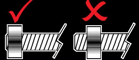
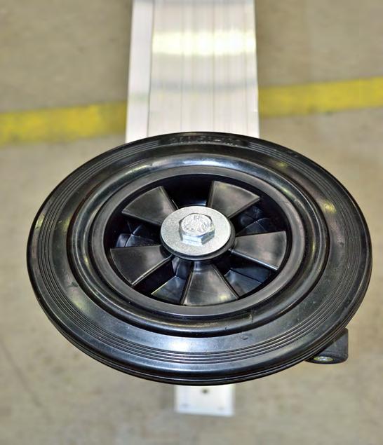
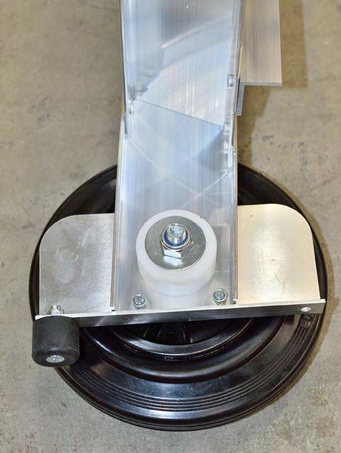
11 Mobilisation Assembly Mobilisation Assembly IMPORTANT: To avoid assembly problems follow these instructions exactly. Work Safely - This assembly is done with the Stockmaster standing upright. Step 1 - Fix the Mobilisation Rails (Rectangular Hollow Section - RHS) to the Frames at A & B (See illustration No. 1) Step 2 - Using the M8 x 40 bolts, nuts and sleeves. Pass the bolt through the hole in the Frame Bracket at C, on the Front Frame. Place a sleeve over the bolt and fit the Rectangular Hollow Section on the inside of the bracket. Secure with a nut - Finger tight only. (See illustration No. 2) Step 3 - Repeat Step 2 at position D on the Rear Frames - Finger tight only. (See illustration No. 3) C Step 4 - Fit the Rubber Bump Stop to the Anti-Tilt Plate as shown using the 6 x 35 screw and nyloc nut. Fit the Anti-Tilt Plate to the end of the Ladder Stile so that the Plate wraps around the end of the Stile. Fix the Plate with the 6mm screws and nuts. Place a Washer over the Anti-Tilt Plate as shown and align the holes and tighten the 6mm screws. (See illustration No. 4) A B A M8 x 40 Note: This item is a Safety Feature to prevent accidental overturning and must be fitted. Step 5 - Fit a Washer to the 12 x 110mm Hex Bolt. Place the Wheel Bearing D inside the Wheel and pass the bolt thru the bearing. Place the Wheel over the Anti-Tilt Plate and pass the bolt thru the Washer, Anti-Tilt Plate and Frame (See illustration No. 5) Step 6 - Fit the Nylon Spacer E to the Bolt on the inside of the Frame. Fit a washer and 12mm Nut to the Bolt and tighten the Nut. (See illustration No. 6) Step 7 - Stand the Ladder upright on a level surface. Stand on the first step taking hold of ladder frame and flexing it so both the feet and wheels sit firmly on the floor. When there is no evidence of rocking, tighten the four Mobilisation to Frame fixings using the Hex Key and Spanner provided. Now tighten the remaining 10mm bolts in the Ladder Frames using the Hex Key only. (Hold the nut in a fixed position with the spanner. Do not rotate the nut.) M8 x 40 D M12 Washer M6 x 12


12 Mobilisation Assembly Mobilisation Assembly D E Illustration 5 Illustration 6
MAG-CONV Basic, 48, 48R & Midline Front Mount
 Parts Required: Tools Used: Mag Wheels Brakes Brake Rods Mounting Bracket Anti Tippers 7/16" Wrench Screw Driver Rubber Mallet 5/8 Wrench 5mm Allen Wrench Step Execution Figures 1 Remove front 5" total
RH-412 STEEL DOORS INSTALLATION INSTRUCTIONS
 RH-412 STEEL DOORS INSTALLATION INSTRUCTIONS By following the steps outlined below, the assembly, installation and adjustment of the steel doors, will be a simple process. Let s start with the Driver Side.
INSTALLATION INSTRUCTIONS RH 412 STEEL DOORS
 By following the steps outlined below, the assembly, installation and adjustment of the steel doors, will be a simple process. Let s start with the Driver Side. Note: Having the hood open makes the job
INSTRUCTION MANUAL MOBILE SAFETY STEPS
 INSTRUCTION MANUAL MOBILE SAFETY STEPS CONTENTS Safety First 3 Assembly Configurations 3 Component List 4-5 Build Method 6-15 SAFETY FIRST Introduction Please read this manual carefully and completely
Assembly Instructions 10 X 10 Aluminum Frame Building
 Assembly Instructions 10 X 10 Aluminum Frame Building 27 97 9 8 47 36 74 52 10 10 X 10 Square Building W/ Dome Includes: The Steel Entry Door with a Dead Bolt Lock assembly and Aluminum Door Frame. Metal
Instruction Guide 4A90L
 Instruction Guide 4A90L Kargo Master Rancho Cordova, CA 95742 800-343-7486 CustomerService@KargoMaster.com DATE: *PLEASE READ ALL INSTRUCTIONS AND WARNINGS PRIOR TO ASSEMBLING, INSTALLING, AND USING THIS
Replacing the Reciprocator on the SWF Compact Series Machine (601C and 1201C)
") Follow the instructions below to replace the reciprocator in the SWF Compact series machines. The tools required can be found in the tool kit that came with the machine. Preparation 1. First, place the
Follow the instructions below to replace the reciprocator in the SWF Compact series machines. The tools required can be found in the tool kit that came with the machine. Preparation 1. First, place the
25-200H. 12 Planer / Jointer. with Helical Cutterhead. Parts List.
 25-200H 12 Planer / Jointer with Helical Cutterhead 4001824 Parts List www.rikontools.com CABINET ASSEMBLY PARTS EXPLOSION & PARTS LIST KEY NO. DESCRIPTION KEY NO. DESCRIPTION 1 Pan Head Screw M6x12 P25-200H-1
55000/55010 Installation Instructions
 A. Install 55015 B. Bolt roof rails, 55020/55025, to front hoop. C. Assemble 55026 D. To install without drilling into bumper. E. If mounting directly to bumper. A. 55015 Installation Instructions 55000/55010
08+ KAWASAKI KLR PD NERF
 08+ KAWASAKI KLR PD NERF 0505-1299 Before you begin, place the bike on a hard level surface where you have room to work. Lay out the parts included in this kit and compare to the parts list on page 5 of
TIRE RACK INSTALLATION INSTRUCTIONS Dodge Sprinter
 Aluminess Products Inc 9402 Wheatlands Ct. #A Santee, CA 92071 619-449-9930 TIRE RACK INSTALLATION INSTRUCTIONS 07-11 Dodge Sprinter Please read before beginning Stainless steel hardware may bind together
Sit Down Table Assembly Instructions
 Sit Down Table Assembly Instructions Parts that come with your sit down table A B C D E F G H I J K L M N Extension leaf Table with cutout for machine Two table legs One table leg with long support One
For additional assistance call
 The following pages will help guide you through the process of assembling your new 48 custom prize wheel. Choose an assembly area with plenty of room to lay your pieces on the floor and also a bench or
Installation Instructions Kit, Base Rail Bracket Part # 31413
 Installation Instructions Kit, Base Rail Bracket Part # 31413 Dealer / Installer: Provide a copy of these Instructions to the end user of this product. These Instructions provide important operating and
ASSEMBLY OF THE KNOCKED-DOWN LADDERS: 8 to 12 STEPS STANDARD TOP AND SAFELOCK REQUIRED TOOLS
 ASSEMBLY OF THE KNOCKED-DOWN LADDERS: 8 to 12 STEPS STANDARD TOP AND SAFELOCK REQUIRED TOOLS SAFETY GLASSES 7/16" WRENCH OR SOCKET STEP LADDER OF APPROPRIATE HEIGHT (2) 9/16" WRENCHES OR SOCKETS RUBBER
Assembly Instructions 10 X 10 Aluminum Roof Support
 Assembly Instructions 10 X 10 Aluminum Roof Support Aluminum Roof Support Bolt Package 16-5/16 X 2 ¼ SS Bolt 24-5/16 X 1 SS Bolt 40-5/16 SS Nylon Lock Nuts 16-5/16 SS Flat Washers 28-4 ½ Wood Screws 36-1
INSTALLATION INSTRUCTIONS
 INSTALLATION INSTRUCTIONS Trans4mer Grille Guard/Winch Mount Kit 645 For Chevrolet Silverado 500HD & 3500 This WARN Trans4mer system can be customized to give your Chevy Silverado a wide variety of looks,
Assembly Instructions
 Unite Panel System Hinge Door July 2016 #12 x / slotted hex washer head bolt Figure 1 threshold bracket frame Detail F threshold bracket threshold bracket (installed) #12 x / slotted hex washer head bolt
4099T Parts List. Front Bow Assy. (1) Rear Bow Assy. (1) Long Mounting Rail (2) Short Mounting Rail (2)
 Rear Bow Assy. (1) Long Mounting Rail (2) Short Mounting Rail (2)") 4099T Parts List Ver.2 Front Bow Assy. (1) Rear Bow Assy. (1) Small Mnt Foot (2) Large Mount Foot (2) Ladder Hook (2) Ladder Stop (2) Handle Extension (1) Long Mounting Rail (2) Short Mounting Rail (2)
4099T Parts List Ver.2 Front Bow Assy. (1) Rear Bow Assy. (1) Small Mnt Foot (2) Large Mount Foot (2) Ladder Hook (2) Ladder Stop (2) Handle Extension (1) Long Mounting Rail (2) Short Mounting Rail (2)
SEAT-831. Seat Box Kit. Club Car Precedent. Installation Instructions
 SEAT-831 Seat Box Kit Club Car Precedent Installation Instructions Contents of SEAT-831 Seat Box Kit: a (1 ea.) Seat Box Platform b (1 ea.) Front Seat Box Plate c (1 ea.) Foot Plate d (1 ea.) Tailgate
EASY POOL STEP (NE113)
") EASY POOL STEP (NE113) FOR USE WITH: EASY POOL STEP (NE113) (1 CARTON) EASY POOL STEP WITH OUTSIDE LADDER (NE126) EASY POOL STEP ENTRY SYSTEM (NE138) (With Gate) (4 CARTONS) Above are the options available
EASY POOL STEP (NE113) FOR USE WITH: EASY POOL STEP (NE113) (1 CARTON) EASY POOL STEP WITH OUTSIDE LADDER (NE126) EASY POOL STEP ENTRY SYSTEM (NE138) (With Gate) (4 CARTONS) Above are the options available
Gared Pro-S Portable Backstop
 Models: 9616 & 9618 Installation, Operation and Maintenance Instructions Please read all instructions before attempting installation or operation of these units SAVE THESE INSTRUCTIONS FOR FUTURE USE PUBLICATION
8mm x 25mm "Z" Bolt Plates. (2) Tube Spacers. (2) 12mm Bolt Plates w/ Nut
 Tube Spacers. (2) 12mm Bolt Plates w/ Nut") PARTS LIST: 1 Grille Guard 10 12mm Lock Washers 1 Driver/Left Side Frame Mounting Bracket 8 12mm Hex Nuts 1 Passenger/Right Side Frame Mounting Bracket 2 10-1.50mm x 25mm Button Head Bolts 1 Driver/Left
PARTS LIST: 1 Grille Guard 10 12mm Lock Washers 1 Driver/Left Side Frame Mounting Bracket 8 12mm Hex Nuts 1 Passenger/Right Side Frame Mounting Bracket 2 10-1.50mm x 25mm Button Head Bolts 1 Driver/Left
Joiner Kit For Models N388, C450, E402B, E411T, E415H, E440T, E442B, E521T and E522B
 Joiner Kit For Models N388, C450, E402B, E411T, E415H, E440T, E442B, E521T and E522B KIT COMPONENTS Part Illustration Description Rear Bracket Front Lower Bracket Front Upper Bracket KIT APPLICATION This
40993 Parts List. Front Bow Assy.(1) Rear Bow Assy.(1)
 Rear Bow Assy.(1)") 40993 Parts List Front Bow Assy.(1) Rear Bow Assy.(1) Rail Mnt Foot(4) Ladder Hook (2) Ladder Stop (2) Mounting Clip-ProMaster Only (6) Mounting Bracket(6) Long Mounting Rail(2) Short Mounting Rail(2)
40993 Parts List Front Bow Assy.(1) Rear Bow Assy.(1) Rail Mnt Foot(4) Ladder Hook (2) Ladder Stop (2) Mounting Clip-ProMaster Only (6) Mounting Bracket(6) Long Mounting Rail(2) Short Mounting Rail(2)
INSTALLATION GUIDE Rear Bumper. Jeep JL Wrangler
 INSTALLATION GUIDE Rear Bumper Jeep JL Wrangler Dual Swing System 1A From the stock bumper you removed from vehicle, you ll need to take the parking sensor wiring from it and feed it into the new bumper.
EASY-IN POOL STEP SYSTEM NE132
 EASY-IN POOL STEP SYSTEM NE132 This instruction manual features multiple guides for the step unit components. 7939 EASY POOL STEP (NE113) FOR USE WITH: EASY-IN POOL STEP (NE126) 6492 PARTS & HARDWARE FOR
KIT. Assembly Instructions. HayDay, LLC
 KIT Assembly Instructions HayDay, LLC 1-800-732-1654 www.stablegrazer.com Read completely through the assembly instructions before starting assembly. The Stable Grazer Kit comes in two boxes. Remove all
GlideRite Retractable Cover System For HotSpring & Tiger River Spas (except Classic & pre-2000 Landmark Spas)
") List of Contents Quantity Description 12 #10 x 1 ½ Flat Head Phillips Screw (see pg. 2) 2 #10 x ½ Pan Head Phillips Screw (see pg. 2) 8 ¼ x 2 ½ Lag Bolt (see pg. 2) 7 ¼ 20 x 5 / 8 Hex Head Bolt (see pg.
List of Contents Quantity Description 12 #10 x 1 ½ Flat Head Phillips Screw (see pg. 2) 2 #10 x ½ Pan Head Phillips Screw (see pg. 2) 8 ¼ x 2 ½ Lag Bolt (see pg. 2) 7 ¼ 20 x 5 / 8 Hex Head Bolt (see pg.
TITAN2-EDGE Public Access Computer Station Dual Track
 TITAN2-EDGE Public Access Computer Station Dual Track TITAN2-EDGE Rev A 6/17 Model TITAN2-EDGE ASSEMBLY AND ADJUSTMENT TITAN2-EDGE PARTS AND TOOLS PLEASE REVIEW these instructions before beginning the
This manual will aid in the assembly of the FireBall V90 and FireBall X90. The assembly of both machines will be identical, unless specified.
 This manual will aid in the assembly of the FireBall V90 and FireBall X90. The assembly of both machines will be identical, unless specified. Step #1 Lay all parts out to verify quantities. (2) 2 x 25-1/4
HD installation guide
 JANUS INTERNATIONAL 1 866 562 2580 www.janusintl.c o m 1950 1950HD installation guide RIGHT DRIVE END SHOWN LH OPPOSITE LEFT TENSION END SHOWN RH OPPOSITE PUSH-UP OPERATION 1950 1950HD SHOWN A rolling
OPERATIONAL MANUAL V1.0. Removing/Replacing Blades
 OPERATIONAL MANUAL V1.0 BLUEROCK WS-212 Wire Stripper Removing/Replacing Blades CAUTION!! IMPORTANT!! DANGER!! WARNING!! DISCONNECT MACHINE FROM POWER BEFORE PROCEEDING!! Estimated Completion Time: 90
Range height adjustable assembly
 Table of contents Digital handset operation 3 Height adjustable bench kit 4-5 Cable carrier 6 Ganging tray and ganging rail 7 Height adjustable return frame kit 8 Cable entry pole 9 24 and 30 d worksurfaces
8.5 Ton Assembly Instructions
 8.5 Ton Assembly Instructions Parts list for assembly. 6- Legs 2 1/2 Angle X 92 Long 6- Cone Supports 2 Angle X 60 Long 6-1 1/4 Angle X 27 1/4 Long. 12-1 1/4 Angles X 42 Long 6-1 Flat Straps 23 3/4 Long
KAWASAKI KLRE PD NERF HTP4-8-5 & HIGHWAY PEGS HTP4-1-4B
 Thank you for purchasing Happy Trails products. Our products are proudly hand made in Boise Idaho, USA. If you have any questions or concerns about the installation of this product, please contact us directly
PRE-ENGINEERED HORSE STALL SYSTEMS SDFD SLIDING DOOR c/w FOLD-DOWN GRILL. & Assembly. Installation Instructions
 PRE-ENGINEERED HORSE STALL SYSTEMS 4800 SDFD SLIDING DOOR c/w FOLD-DOWN GRILL & Assembly Installation Instructions 4800 SDFD Sliding Door c/w Fold-Down Grill Components - 1 3 /4" x 2" x 88" channels (2)
Side Winder R o u t e r L i f t.
 Woodpeckers PRECISION WOODWORKING TOOLS Side Winder R o u t e r L i f t. INSTALLATION INSTRUCTIONS The wrench handle must be pointing left in order to fully insert or remove it. Lift Wrench Once fully
The Festival Assembly Instructions
 The Festival Assembly Instructions Toll Free: 866.768.8465 Hours: 9-5 Monday-Friday EST www.homeplacestructures.com Package ships as shown CONTACT INFORMATION: HomePlace Structures 301 Commerce Drive New
4832A Installation Sheet Part List
 4832A Installation Sheet Part List (1) 4016A-43-003 Qty 1- (2) 4016A-43-002 Qty 1- (3) 4016A-43-001 Qty 2- (4) 4016A-10-005 Qty 1- (5) 4016A-43-004L Qty 1- Mounting Bolt Kit (A) (K) Qty 2 - Qty 6 - M10
Installation Instructions for the AlphaDeck Staging System
 Installation Instructions for the AlphaDeck Staging System Step 1 - Preparation A. Before setting up your system, determine the location where the stage will be installed and locate all the parts you will
INSTALLATION INSTRUCTIONS SIDE BAR FORD ESCAPE & MAZDA TRIBUTE PART #
 INSTALLATION INSTRUCTIONS SIDE BAR 2008-2010 FORD ESCAPE & MAZDA TRIBUTE PART # 50136 50137 PARTS LIST: 1 Driver/Left Sidebar 2 10-1.50mm x 35mm Bolt Plate 1 Passenger/Right Sidebar 2 10-1.50mm x 30mm
Real Life Ninja Complete Starter Pack (14ft. Warped Wall) Assembly Instructions
 Assembly Instructions") MATERIALS: 3 - Main Sections (Only 2 Sections for 10 ) 8 3 deck screws for joining sections inside of 2 Rock Wall Panels (with pre-installed t-nuts. Top panel comes with ladder mounting block preinstalled.)
MATERIALS: 3 - Main Sections (Only 2 Sections for 10 ) 8 3 deck screws for joining sections inside of 2 Rock Wall Panels (with pre-installed t-nuts. Top panel comes with ladder mounting block preinstalled.)
Installation Guide 40670
 Installation Guide 40670 Kargo Master Rancho Cordova, CA 95742 800-343-7486 CustomerService@KargoMaster.com DATE: Installation Instructions 40670 *PLEASE READ ALL INSTRUCTIONS AND WARNINGS PRIOR TO ASSEMBLING,
Size Grade Torque 9/ ft/lbs. 5/ ft/lbs. 3/ ft/lbs. 7/ ft/lbs ft/lbs.
 8-3 HJ3205,Rev 4 BOlT TORQUE SPECIfICATIONS STANDARD BOlTS: Size Grade Torque 5/6 5 20 ft/lbs. 3/8 5 35 ft/lbs. 7/6 5 56 ft/lbs. /2 5 85 ft/lbs. Size Grade Torque 9/6 5 23 ft/lbs. 5/8 5 70 ft/lbs. 3/4
Section 1 Safety working at height
 Contents Section 1 Safety working at height. Section 2 Hi-Step package contents & parts identification. Section 3 Assembly. Section 4 Operation. Section 5 Maintenance. Section 6 Extender package contents
Q-Zone Hoop-Frame. Assembly Instructions. Copyright July 11, 2018 Grace Company (Reproduction Prohibited) Version 1.8
 Version 1.8") Q-Zone Hoop-Frame Assembly Instructions Copyright July 11, 2018 Grace Company (Reproduction Prohibited) Version 1.8 Table of Contents Table of Contents... i Warranty... ii Parts List Box 1...iii Box 2...
Q-Zone Hoop-Frame Assembly Instructions Copyright July 11, 2018 Grace Company (Reproduction Prohibited) Version 1.8 Table of Contents Table of Contents... i Warranty... ii Parts List Box 1...iii Box 2...
ASSEMBLY INSTRUCTIONS
 ASSEMBLY INSTRUCTIONS PRINTED IN USA Assembly Instructions Include: P/N: LL-04-5 Step : Site Preparation Step 0: Guard Rail Installation Step : Leg Assembly Step : Stairs Step 3-8: Setting the Stage Step
INS T A L L A TIO N INS T R U C TIO N S. Ceiling Mount Track System
 Ceiling Mount Track System 10.26.2016 Specifications Ceiling Post: Unassembled 2-7/8 Assembled 1-11/16 7/8 7-9/16 5-7/8 3/8 2 Tubes 1/2 2-3/8 5 Parts and Tools Tools Needed Tape Measure Pencil Drill with
GlideRite Retractable Cover System For Hot Spot Spas (SE & SLX only)
") List of Contents Quantity Description 12 #10 x 1 ½ Flat Head Phillips Screw (see pg. 2) 2 #10 x ½ Pan Head Phillips Screw (see pg. 2) 8 ¼ x 2 ½ Lag Bolt (see pg. 2) 7 ¼ 20 x 5 / 8 Hex Head Bolt (see pg.
List of Contents Quantity Description 12 #10 x 1 ½ Flat Head Phillips Screw (see pg. 2) 2 #10 x ½ Pan Head Phillips Screw (see pg. 2) 8 ¼ x 2 ½ Lag Bolt (see pg. 2) 7 ¼ 20 x 5 / 8 Hex Head Bolt (see pg.
F i t t i n g t h e N e w L a n d i n g G e a r t o Y o u r S k y J i b V 1
 F i t t i n g t h e N e w L a n d i n g G e a r t o Y o u r S k y J i b V 1 1 P a r t s L i s t : S t a n d a r d L a n d i n g G e a r U p g r a d e Product Code Parts + Spares Product Code Parts + Spares
Side Mount INSTRUCTION BOOKLET #C122 BED STYLE: PARK CITY
 Side Mount BED STYLE: PARK CITY INSTRUCTION BOOKLET #C1 WARNING! ALL MURPHY/WALLBED SYSTEMS CONTAIN STORED ENERGY. FAILURE TO USE AND FOLLOW THESE INSTRUCTIONS DURING THE INSTALLATION PROCESS COULD RESULT
INSTRUCTION BOOKLET #34. For Wallbed models: KING SIZE SIERRA WITH STORAGE HEADBOARD
 For Wallbed models: KING SIZE SIERRA WITH STORAGE HEADBOARD INSTRUCTION BOOKLET #34 WARNING! ALL MURPHY/WALLBED SYSTEMS CONTAIN STORED ENERGY. FAILURE TO USE AND FOLLOW THESE INSTRUCTIONS DURING THE INSTALLATION
Ford Pick Up Rear leaf Spring Kit Installation Instructions
 1948-1956 Ford Pick Up Rear leaf Spring Kit Installation Instructions 1-800-984-6259 www.totalcostinvolved.com Parts 48 inch leaf (2) springs (4) U-bolts 3/8-24 x l 1/4bolts (16) & nuts (2) 1/2-20 x 4
IDR assembly instructions:
 IDR assembly instructions: Required Tools: 2 X 12mm Open End Wrench 14mm open end wrench #2 Phillips Head Screw Driver (Drill with adjustable torque clutch recommended) 8mm nut driver (Supplied in IDR-AK)
RBP-1215B-RX DODGE RAM QUAD CAB RX3
 RBP-1215B-RX3 2002-2017 DODGE RAM 15-3500 QUAD CAB RX3 Passenger side RX-3 Side Step Drill Template Passenger side rear Modular Bracket (6) L Support Brackets Driver side rear Modular Bracket Driver side
JK Rear Inner Fenders
 INSTALLATION INSTRUCTIONS INST-17-05-080_A JK Rear Inner Fenders IMPORTANT: Thank you for purchasing this Poison Spyder product. Please read through this entire document before proceeding with installation.
INSTALLATION INSTRUCTIONS
 TEL -866-XANATOS INSTALLATION INSTRUCTIONS PART#: 7D5000SS\7D500A GRILL GUARD FOR DODGE SPRINTER 07-09 PARTS LIST: 8 6 Grille Guard Driver/Left Frame Mounting Passenger/Right Frame Mounting Driver/Left
set of safety brace steel cable draw-up gate kpl
 0324101 7108020 8208100 Order-nr. Description Number 0324101 safety brace steel cable draw-up gate 2 7108020 hexagon-head tap bolt M8x20 galv. 2 8208100 hexagon nut M8 galv. 2 set of safety brace steel
Installation Instructions - Model V4JSD 1
 Installation Instructions - Model V4JSD 1 Support Assemblies: Parts list: (Note see enclosed cut sheet for quantities and dimensional information) A vertical structural member (1 ½ x 1 ½ modular frame)
Passage 4 Bike Hitch Rack
 Thank you for purchasing the XPORT Passage 4 Bike Hitch rack. This rack will securely carry up to 4 bicycles. The trigger and lift assist mechanisms allow the rack to tilt up or down allowing easy access
OWNERS MANUAL. Model No LB. POLY PRO SPIKER/SPREADER. CAUTION: Read Rules for Safe Operation and Instructions Carefully
 OWNERS MANUAL Model No. -0301 CAUTION: Read Rules for Safe Operation and Instructions Carefully 17 LB. POLY PRO SPIKER/SPREADER Safety Assembly Operation Maintenance Parts PRINTED IN U.S.A. FORM NO. 78
Kai Installation Instructions
 Kai Installation Instructions Before Beginning Installation Read through the entire instruction thoroughly A minimum of 2 people are required for this assembly These instructions reflect typical assemblies;
Art Rack Assembly Instructions:
 Art Rack Assembly Instructions: ** PIECES ARE POWDER COATED Do not lay pieces on top of each other or on a hard, rough surface if possible. All bolts will pass from outside towards inside of the cage.
SAM. Model: STV-C65 LCD Mobile Visualized Stand Instruction Manual. Weight Capacity: 1251bs / 56.7kg Suits LCD Flat Panel Display: 42"-55" Page 20
 SAM Model: STV-C65 LCD Mobile Visualized Stand Instruction Manual Weight Capacity: 1251bs / 56.7kg Suits LCD Flat Panel Display: 42"-55" 20 Step 6 LCD Mobile Lift Stand Model: STV-C65 Cable management
SINCE 1922 P UBLICATION N O
 SINCE 1922 GARED SPORTS MICRO-Z SET-UP INSTRUCTIONS VERY IMPORTANT! READ INSTRUCTIONS CAREFULLY AND FOLLOW STEP BY STEP SET-UP PROCEDURE P UBLICATION N O. 5 5 1 7 5 2 9 1 6 Recommended tools and accessories.
LB. POLY PRO DROP SPREADER
 owners manual Model No. -02882 17 LB. POLY PRO DROP SPREADER CAUTION: Read Rules for Safe Operation and Instructions Carefully Safety Assembly Operation Maintenance Parts the fastest way to purchase parts
HITCH MOUNT BICYCLE CARRIER Model BC-102
 HITCH MOUNT BICYCLE CARRIER Model BC-102 MAXIMUM LOADING CAPACITY 60 LBS Recommended Tools for Assembly: Open Wrench (2 pc.) Open Wrench (2 pc.) Open Wrench (2 pc.) Size=17mm Size=19mm Size=24mm Assembly
======================================================================================== ( DR / DR) JK WRANGLER MOD RACK
 JK WRANGLER MOD RACK") (10984 4DR / 10982 2DR) JK WRANGLER MOD RACK INSTALLATION SHEET Important Notes: Some brands of windshield light brackets and snorkels may not be compatible with the 10984 MOD Rack System. Body lifts are
(10984 4DR / 10982 2DR) JK WRANGLER MOD RACK INSTALLATION SHEET Important Notes: Some brands of windshield light brackets and snorkels may not be compatible with the 10984 MOD Rack System. Body lifts are
RANGE DIGITAL HANDSET OPERATION. 1. Panel. 2. Initialization Procedure. 3. Move Up & Down. 4. Set Memory Positions. 5. Move to the Memorized Positions
 INSTRUCTION SHEET #2577INS PART #1730534 DIGITAL HANDSET OPERATION OPERATION INSTRUCTIONS 1. Panel 1 Button: Preset 1 2 Button: Preset 2 3 Button: Preset 3 S Button: Select Display: Reads in 1 / 2 " Increments
Kawasaki Teryx 750 Cab Kit* Caution: Before using this product, read this manual and follow all Safety Instructions.
 Owner s Manual Model: Kawasaki Teryx 750 Kawasaki Teryx 750 Cab Kit* Caution: Before using this product, read this manual and follow all Safety Instructions. Safety Instructions Cab Kit Contents Hardware
Star Trac Turbo Trainer Assembly & Setup
 Star Trac Turbo Trainer Use the following procedures to unpack and assemble your Turbo Trainer manufactured by Star Trac. UNPACKING AND PARTS LIST Position the shipping carton so the Heavy End logo is
 INSTRUCTION BOOKLET #C0 Watch step by step installation instructions at: https://www.wallbedsbywilding.com/wallbed-installation-studio-series/ WARNING! ALL MURPHY/WALLBED SYSTEMS CONTAIN STORED ENERGY.
TELESCOPIC GATE MANUFACTURING AND INSTALLATION MANUAL.
 TELESCOPIC GATE MANUFACTURING AND INSTALLATION MANUAL. Telescopic gates have been manufactured for many years essentially in the same way they are largely today. In recent years hardware suppliers have
ABM International, Inc. Navigator Assembly Manual
 ABM International, Inc. 1 1.0: Parts List Tablet (Qty. 1) Tablet mount (Qty. 1) NOTE: Mount may appear and operate different then image below Control Box (Qty. 1) Motor Power Supply (Qty. 1) 2 X-axis motor
Dublin Stalls Installation Instructions
 Dublin Stalls Installation Instructions RAMM Horse Fencing and Stalls 13150 Airport Hwy. Swanton, OH 43558-9615 1-800-434-8456 Rev. 9/13/17 Part Identification Round Track Bracket (4) (Not Painted) Round
Installation Instructions
 Installation Instructions 000964 Revision F Installation Instructions for PIRIT Read this manual fully prior to starting installation. Call American eating Customer ervice with any questions. What you
O W N E R ' S M A N U A L
 TABLE TENNIS TABLE MODEL NOS. T861 T861B O W N E R ' S M A N U A L 1. Read this manual carefully before starting assembly. Read each step completely before beginning each step.. Some smaller parts may
MODUS 770 AND MODUS 1280 (FLAT PACK) OPERATIONAL, ASSEMBLY & FIXING INSTRUCTION LEAFLET
 OPERATIONAL, ASSEMBLY & FIXING INSTRUCTION LEAFLET") MODUS 770 AND MODUS 1280 (FLAT PACK) TM TM OPERATIONAL, ASSEMBLY & FIXING INSTRUCTION LEAFLET NOTE: Ensure that all relevant personnel read the points listed below and that a copy is passed on to staff
MODUS 770 AND MODUS 1280 (FLAT PACK) TM TM OPERATIONAL, ASSEMBLY & FIXING INSTRUCTION LEAFLET NOTE: Ensure that all relevant personnel read the points listed below and that a copy is passed on to staff
Therma-Tru Door Gallery Setup Instructions Swing Unit with Hardware Kit - Hardware Part # MADGSWU15 (Swing Unit) Part # MADGHKSU10 (Hardware Kit)
 Part # MADGHKSU10 (Hardware Kit)") Swing Unit with Hardware Kit - Hardware Tools Included: 4mm Allen Wrench, 6mm Allen Wrench, 8mm T-Handle Allen Wrench (1) 3/4" Drill Bit, (1) 7/32" Drill Bit and Hole Template Guide Tools Required: Phillips
Swing Unit with Hardware Kit - Hardware Tools Included: 4mm Allen Wrench, 6mm Allen Wrench, 8mm T-Handle Allen Wrench (1) 3/4" Drill Bit, (1) 7/32" Drill Bit and Hole Template Guide Tools Required: Phillips
installation guide
 JANUS INTERNATIONAL 1 866 562 2580 w w w. j a n u s i n t l. c o m 2000 2500 3000 installation guide RIGHT DRIVE END SHOWN LH OPPOSITE LEFT TENSION END SHOWN RH OPPOSITE PUSH-UP OPERATION 2000 2500 3000
Showpiece Cabinet Integrated Stand For 32" - 52" LCD HDTV
 Showpiece Cabinet Integrated Stand For 32" - 52" LCD HDTV Installation and Assembly Instructions 2009 Incredible Technologies Inc. Version 0109 Showpiece Cabinet Integrated Stand for 32" - 52" LCD HDTV
 INSTRUCTION BOOKLET #C10 Watch step by step installation instructions at: https://www.wallbedsbywilding.com/wallbed-installation-studio-series/ WARNING! ALL MURPHY/WALLBED SYSTEMS CONTAIN STORED ENERGY.
Assembly, Installation, Operation and Maintenance Instructions Kit, Base Rail Bracket Part # 31852
 . Assembly, Installation, Operation and Maintenance Instructions Kit, Base Rail Bracket Part # 31852 Dealer / Installer: Provide a copy of these instructions to the end user of this product. These instructions
Venetian Blind 25mm Installation Guide Inside Fit option
 Venetian Blind 25mm Installation Guide Inside Fit option Parts 1. Installation bracket (Same bracket used for inside and face fitting) 2. Installation Screw (1 per bracket, Square head) Step 1 Bracket
OWNER'S MANUAL. Please Do Not Return This Product To The Store!
 MODEL NO. T8190SA TABLE TENNIS TABLE OWNER'S MANUAL 1. Read this manual carefully before starting assembly. Read each step completely before beginning each step.. Some smaller parts may be shipped inside
INSTALLING YOUR NEW SPRING LIFT ARM KIT
 INSTALLING YOUR NEW SPRING LIFT ARM KIT 1. Measure the distance that the roof is to be raised. [If your lift system is completely non-functional, you will need to calculate or estimate this distance as
M2 Assembly. M2 Sub-Assemblies mm Belt Sub-Assembly mm Belt Sub-Assembly Spider Sub-Assembly... 4
 M2 Assembly Table of Contents M2 Sub-Assemblies... 3 630mm Belt Sub-Assembly... 3 702mm Belt Sub-Assembly... 3 Spider Sub-Assembly... 4 Idler Bolt Sub-Assembly... 8 Y Motor Sub-Assembly... 9 X Motor Sub-Assembly...
Strata. urniture. Adriana Instructions. Parts in the Arm Box: Parts in the Body Box: Watch our assembly videos at
 1A Watch our assembly videos at www.strataf.com/videos Parts in the Arm Box: Arm - Outside View Arm - Inside View 1B Parts in the Body Box: Back Deck x 1 Seat Deck x 1 with the Feet attached Back Panel
3,500/4,500lb. Vertical Cable Feighner Lift
 3,500/4,500lb. Vertical Cable Feighner Lift CAUTION - PUT SAFETY FIRST 1. Before attempting to install or operate this lift, study and fully understand the proper operating procedures and safety precautions
BABY WOLF LOOM. Assembly Instructions for Knocked-Down Looms
 BABY WOLF LOOM Assembly Instructions for Knocked-Down Looms BEFORE YOU BEGIN Please read through the directions before beginning to assemble your loom. Unpack the loom parts carefully. Do not throw away
GRILLE GUARD SPRINTER VAN (EXCLUDES X4) INCLUDES MERCEDES, FREIGHTLINER AND DODGE PARTS LIST:
 INCLUDES MERCEDES, FREIGHTLINER AND DODGE PARTS LIST:") PARTS LIST: 1 Grille Guard 8 12mm Hex Nuts 1 Driver/Left Side Frame Mounting Bracket 2 10-1.50mm x 25mm Button Head Bolts 1 Passenger/Right Side Frame Mounting Bracket 4 10mm x 20mm OD x 2mm Flat Washers
PARTS LIST: 1 Grille Guard 8 12mm Hex Nuts 1 Driver/Left Side Frame Mounting Bracket 2 10-1.50mm x 25mm Button Head Bolts 1 Passenger/Right Side Frame Mounting Bracket 4 10mm x 20mm OD x 2mm Flat Washers
Pack Mount Instructions:
 Pack Mount Instructions: STEP 1 Mounting upright base to desired surface If mounting to a surface with an accessible backside (such as a thin walled container): Option 1 Discard the Round Mounting Disk
Gardman Lean-to Greenhouse Assembly Instructions
 Page 1 Gardman Lean-to Greenhouse Assembly Instructions Our Help Line provides support and advice to customers of Summer Garden Buildings after ordering. For advice before you buy you can phone us free
Greenhouse Assembly Instructions
 Greenhouse Assembly Instructions Our Help Line provides support and advice to customers of Summer Garden Buildings after ordering. For advice before you buy you can phone us free 7 days a week on 0800
3 wide x 3 deep Video Wall Display Installation Guide
 HoverTrack Series 3 wide x 3 deep Video Wall Display Installation Guide VWD-3X3-X462 This display kit mounts NEC X461UN and X462UNS LCD monitors in a 3 wide by 3 deep landscape configuration. The frame
TROLLA LEAVY 97 CM Lawn sweeper
 TROLLA LEAVY 97 CM Lawn sweeper Artikel nr.: 1008 EN Operating manual 014/1 Dear Customer, Congratulations on your new Trolla product. We hope you will enjoy it. Checkout with your new Trolla product may
Stainless Steel Bench Stand
 Installation Manual Stainless Steel Bench Stand Product(s): 29600 29601 51229 2016 by Fairbanks Scales, Inc. Revision 2 02/16 All rights reserved. Amendment Record STAINLESS STEEL BENCH STAND Document
3 BRACKET TO GUIDE ATTACHMENT. RIGHT END Figure 1. EXTENDED BRACKET (for doors taller than 8-8 ) SERIES 650. RIGHT END COTTER PIN Figure 6
 SERIES 650. RIGHT END COTTER PIN Figure 6") 2 DOOR ARRANGEMENT. A Lay door on a clean floor inside of building and in front of opening (see Figure 1). NOTE: Door can be damaged if laid on unclean surface. B Distribute parts bags, guides, stops and
2 DOOR ARRANGEMENT. A Lay door on a clean floor inside of building and in front of opening (see Figure 1). NOTE: Door can be damaged if laid on unclean surface. B Distribute parts bags, guides, stops and
Oxford Stalls Installation Instructions
 Oxford Stalls Installation Instructions RAMM Horse Fencing and Stalls 13150 Airport Hwy. Swanton, OH 43558-9615 1-800-434-8456 Rev. 8/15/17 Before You Start Typical stall sizes are 10 x 10, 12 x 12 or