WO 2013/ Al. Fig 4a. 2 1 February 2013 ( ) P O P C T
|
|
|
- Sabina Hines
- 5 years ago
- Views:
Transcription
1 (12) INTERNATIONAL APPLICATION PUBLISHED UNDER THE PATENT COOPERATION TREATY (PCT) (19) World Intellectual Property Organization International Bureau (10) International Publication Number (43) International Publication Date WO 2013/ Al 2 1 February 2013 ( ) P O P C T (51) International Patent Classification: (72) Inventors; and E04F 15/02 ( ) E04F 15/04 ( ) (75) Inventors/Applicants (for US only): PERVAN, Tony [SE/SE]; Ostermalmsgatan 89, SE Stockholm (SE). (21) International Application Number: PERVAN, Darko [SE/SE]; Bygatan 30, SE Viken PCT/SE20 12/ (SE). (22) International Filing Date: (74) Agent: ENGSTRAND, Ola; c/o Valinge Innovation AB, 14 August 2012 ( ) Prastavagen 513, SE Viken (SE). (25) Filing Language: English (81) Designated States (unless otherwise indicated, for every (26) Publication Language: English kind of national protection available): AE, AG, AL, AM, AO, AT, AU, AZ, BA, BB, BG, BH, BN, BR, BW, BY, (30) Priority Data: BZ, CA, CH, CL, CN, CO, CR, CU, CZ, DE, DK, DM, August ( ) SE DO, DZ, EC, EE, EG, ES, FI, GB, GD, GE, GH, GM, GT, 61/523, August ( ) US HN, HR, HU, ID, IL, IN, IS, JP, KE, KG, KM, KN, KP, (71) Applicant (for all designated States except US): KR, KZ, LA, LC, LK, LR, LS, LT, LU, LY, MA, MD, VALINGE FLOORING TECHNOLOGY AB [SE/SE]; ME, MG, MK, MN, MW, MX, MY, MZ, NA, NG, NI, Prastavagen 5 13, SE Viken (SE). NO, NZ, OM, PE, PG, PH, PL, PT, QA, RO, RS, RU, RW, SC, SD, SE, SG, SK, SL, SM, ST, SV, SY, TH, TJ, TM, (54) Title: MECHANICAL LOCKING SYSTEM FOR FLOOR PANELS [Continued on next page] Fig 4a (57) Abstract: Building panels, especially floor panels are shown, which are provided with a vertical locking system on adjacent edges including a displaceable tongue that has a main tongue body and sep arate spring parts attached to the body. 4 1
2 w o 2013/ Λ llll II II 11III III II I II II III II III II I II TN, TR, TT, TZ, UA, UG, US, UZ, VC, VN, ZA, ZM, Declarations under Rule 4.17: ZW. as to applicant's entitlement to apply for and be granted (84) Designated States (unless otherwise indicated, for every a patent (Rule 4. 7(H)) kind of regional protection available): ARIPO (BW, GH, Published: GM, KE, LR, LS, MW, MZ, NA, RW, SD, SL, SZ, TZ, UG, ZM, ZW), Eurasian (AM, AZ, BY, KG, KZ, RU, TJ, with international search report (Art. 21(3)) TM), European (AL, AT, BE, BG, CH, CY, CZ, DE, DK, before the expiration of the time limit for amending the EE, ES, FI, FR, GB, GR, HR, HU, IE, IS, IT, LT, LU, claims and to be republished in the event of receipt of LV, MC, MK, MT, NL, NO, PL, PT, RO, RS, SE, SI, SK, amendments (Rule 48.2(h)) SM, TR), OAPI (BF, BJ, CF, CG, CI, CM, GA, GN, GQ, GW, ML, MR, NE, SN, TD, TG).
3 MECHANICAL LOCKING SYSTEM FOR FLOOR PANELS TECHNICAL FIELD The disclosure generally relates to the field o f mechanical locking systems for floor panels and building panels. The disclosure shows floorboards, locking systems, installation methods and production methods. FIELD OF APPLICATION OF THE INVENTION Embodiments o f the present invention are particularly suitable for use in floating floors, which are formed o f floor panels which are joined mechanically with a locking system integrated with the floor panel, i.e. mounted at the factory, are made up o f one or more upper layers o f wood or wood veneer, decorative laminate, powder based surfaces or decorative plastic material, an intermediate core o f wood-fibre-based material or plastic material and preferably a lower balancing layer on the rear side o f the core. Floor panels with a surface layer o f cork, linoleum, rubber or soft wear layers, for instance needle felt glued to a board, printed and preferably also var nished surface and floors with hard surfaces such a s stone, tile and similar materials are included. Embodiments o f the invention may also b e used for joining building panels which preferably contain a board material for instance wall panels, ceilings, furniture components and similar. The following description o f known technique, problems o f known systems and objects and features o f the invention will therefore, a s a non-restrictive example, b e aimed above all at this field o f application and in particular at panels formed a s rectangular floor panels with long and shorts edges intended to b e mechanically joined to each other on both long and short edges.
4 The long and short edges are mainly used to simplify the description o f embodiment o f the invention. The panels may b e square. Embodiments o f the invention are preferably used on the short edges. It should b e emphasised that embodiments o f the invention may b e used in any floor panel and it may b e combined with all types o f known locking system formed on the long edges, where the floor panels are intended to b e joined using a mechanical locking system connecting the panels in the horizontal and vertical directions on at least two adjacent sides. BACKGROUND OF THE INVENTION Laminate flooring usually comprises a core o f a 6-12 mm fibre board, a 0,2-0,8 mm thick upper decorative surface layer o f laminate and a 0,1-0,6 mm thick lower balancing layer o f laminate, plastic, paper or like material. A laminate surface comprises o f melamine-impregnated paper. The most common core material i s fibreboard with high density and good stability usually called HDF - High Density Fibreboard. Sometimes also MDF - Medium Density Fibreboard - i s used a s core. Traditional laminate floor panels o f this type have been joined b y means o f glued tongue-and-groove joints. In addition to such traditional floors, floor panels have been developed which do not require the use o f glue and instead are joined mechanically b y means o f so-called mechanical locking systems. These systems comprise locking means, which lock the panels horizontally and vertically. The mechanical locking systems are usually formed b y machining o f the core o f the panel. Alternatively, parts o f the locking system may b e formed o f a separate material, for instance aluminium or HDF, which i s integrated with the floor panel, i.e. joined
5 with the floor panel in connection with the manufacture thereof. The main advantages o f floating floors with mechanical locking systems are that they are easy to install. They may also easily b e taken up again and used once more at a different location. DEFINITION OF SOME TERMS In the following text, the visible surface o f the installed floor panel i s called "front side", while the opposite side o f the floor panel, facing the sub floor, i s called "rear side". The edge between the front and rear side i s called "joint edge". By "horizontal plane" i s meant a plane, which extends parallel to the outer part o f the surface layer. Immediately juxtaposed upper parts o f two adjacent joint edges o f two joined floor panels together define a "vertical plane" perpendicular to the horizontal plane. By "inner vertical tongue plane" i s meant a plane, which i s parallel with a vertical plane that intersects the outer and most inner part o f the main tongue body. By "vertical locking" i s meant locking parallel to the vertical plane. By "horizontal locking" i s meant locking parallel to the horizontal plane. By "up" i s meant towards the front side, b y "down" towards the rear side, b y "inwardly" mainly horizontally towards an inner and centre part o f the panel and b y "outwardly" mainly horizontally away from the centre part o f the panel. By "locking systems" are meant co acting connecting elements, which connect the floor panels vertically and/or horizontally. RELATED ART AND PROBLEMS THEREOF For mechanical joining o f long edges a s well a s short edges in the vertical and in the first horizontal direction perpendicular to the edges several methods may
6 b e used. One o f the most used methods i s the angle-snap method. The long edges are installed by angling. The panel i s than displaced in locked position along the long side. The short edges are locked by horizontal snapping. The vertical connection i s generally a tongue and a groove. During the horizontal displacement, a strip with a locking element i s bent and when the edges are in contact, the strip springs back and a locking element enters a locking groove and locks the panels horizontally. Such a snap connection i s complicated since a hammer and a tapping block usually needs to b e used to overcome the friction between the long edges and to bend the strip during the snapping action. Similar locking systems may also b e produced with a rigid strip and they are connected with an angling-angling method where both short and long edges are angled into a locked position. Recently new and very efficient locking systems have been introduced with a separate flexible or displaceable integrated tongue on the short edge that allows installation with only an angling action, generally referred to a s "vertical folding". Such a system i s described in WO 03/ and WO 2006/ (Valinge Innovation AB) Several versions are used on the market. Figure la-lc show a locking system comprising a displaceable tongue 3 0 that i s displaced inwardly into a displacement groove 2 1 and outwardly into a tongue groove 2 0 when the edges o f adjacent panels 1,1' are displaced vertically against each other. Such systems are referred to a s vertical snap systems and they provide an automatically locking during the folding action. The displaceable tongue 3 0 locks the panels vertically parallel to a vertical plane V P perpendicular to a main horizontal plane o f the panels. A
7 locking strip 6 with a locking element 8 that cooperates with a locking groove 1 4 in the adjacent panel 1 ' locks the edges horizontally parallel to a main horizontal plane HP. Figures 2a-2e show one o f the most used flexible tongues 3 0 the so-called bristle tongue, which i s formed in one piece. Such a displaceable tongue 3 0 comprises a main tongue body 3 1 that i s strong and rather rigid, flexible protrusions 3 8 that provides the necessary flexibility and friction connections 3 6 that prevents the tongue to fall out from the displacement groove 2 1 during transport and installation o f the floor panels. Bristle tongues are made o f high quality plastic material reinforced with glass fibres. The flexibility must b e considerable and allow that a flexible tongue i s displaced in two directions about 1-2 mm during locking. The tongues are injection moulded and formed into tongue blanks 5 0 that may comprise up to 32 tongues. The tongues are connected to rails 5 1 which are used to feed the tongues during production when they are separated from the tongue blank and inserted into an edge o f a panel. Although such locking systems and one-piece bristle tongues are very efficient and provide a strong and reliable locking, there i s still a room for improvements. One disadvantage i s that the whole tongue blank 5 0 i s made o f a high quality plastic material that i s rather costly. Such high quality material i s only needed in those parts o f the tongue that form the flexible protrusions 36. High quality plastic material reinforced with glass fibres i s not required in the parts o f the tongue that comprises the main tongue body 3 1 and the rails 51. About 60% o f a tongue blank i s made o f a material that i s o f a higher quality than required for its specific function.
8 A second disadvantage i s that each tongue blank 5 0 must b e individually designed for a specific width o f a floor panel and this requires a wide range o f expensive injection moulding tongues for each width. A third disadvantage i s that glass fibre reinforced plastic material i s difficult to recycle and the scrap from the rails has a very low material value. It would b e a major advantage i f the tongues could b e made in a more cost efficient way regarding material costs and different tongue lengths. It i s known from the above-mentioned publications that a displaceable tongue may b e formed from a sheet shaped materials such a s HDF. This may decrease the material costs with about 80% compared to high cost plastic materials. The flexibility may b e obtained by a flexible rubber strip that i s inserted into an inner part o f a displacement groove or attached to an inner part o f an extruded plastic section. Such a two-piece tongue will not provide sufficient strength and flexibility since the compression takes place outside the displaceable tongue between the inner part o f a displacement groove and the inner edge o f the tongue body. The groove must b e rather deep and this will have a negative effect on the joint stability. It i s not shown how the flexible material should b e attached to tongues in a tongue blank and how friction connections should b e formed that allow the tongue to slide in the groove without the risk that the tongue will fall out from the groove after production. The cost o f the flexible material i s still rather high since the flexible part extends along the whole tongue length.
9 SUMMARY OF THE INVENTION An overall objective o f embodiments o f the present invention i s to provide an improved and more cost efficient locking system for primarily rectangular floor panels with long and short edges installed in parallel rows, which allows that the short edges may b e locked to each other automatically with a vertical snap action caused b y a tongue that i s displaced in a groove. More specifically the objective i s to provide a locking system with a separate displaceable tongue that i s formed o f different materials such that the cost and function may b e optimised. Another specific objective i s to provide a tongue that may b e produced in different lengths without the need o f individual injection moulding tools specially designed for each tongue length. The above objects o f embodiment o f the invention may b e achieved wholly or partly by locking systems and floor panels according to the disclosure. Embodiments o f the invention are evident from the description and drawings. A first aspect o f the invention i s building panels provided with a locking system for vertical locking o f a first and a second building panel by a vertical displacement o f the panel relative each other. A displaceable tongue i s attached into a sidewardly open displacement groove provided at an edge o f the first panel. Said tongue cooperates with a tongue groove provided at an adjacent edge o f the second panel for locking the edges vertically. A strip protrudes below the displacement groove and outwardly beyond the upper part o f the edge or below the tongue groove and outwardly beyond the upper part o f the adjacent edge. The displaceable tongue comprises a main tongue body
10 extending along the edge o f the first panel and a separate flexible spring part attached to the main tongue body. The separate spring part i s located in an inner part o f the displacement groove The tongue may comprise two or more spring parts that are spaced from each other in the length direction o f the main tongue body. The spring parts may b e asymmetric in a direction along the edge. The main tongue body and the spring parts may b e made o f different materials The tongue may comprise an upwardly or downwardly open fixing groove. The spring parts may comprise an upwardly or downwardly extending fixing connection part. The spring part may during locking b e displaced or compressed horizontally beyond a vertical tongue plane that comprises an inner part o f the tongue body. The spring part may overlap a part or the tongue body during locking. The spring part may b e located in a vertically open flexing cavity formed in the tongue body. The building panels are preferably floor panels. A second aspect o f the invention i s a tongue blank comprising at least two tongues which are each designed to b e inserted into a groove o f a building panel and lock the building panel to an adjacent building panel. A part
11 o f the tongue i s configured to b e displaced during locking. The tongues are o f an elongated shape and each tongue comprises a separate spring part connected to a main body o f the tongue. The separate spring part may b e asymmetric in the length direction o f the tongue. Each tongue may comprise two or more spring parts that are spaced from each other in the length direction o f the tongue. BRIEF DESCRIPTION OF THE DRAWINGS The disclosure will in the following b e described in connection to exemplary embodiments and in greater detail with reference to the appended exemplary drawings, wherein: Figs la-c illustrate locking systems according to known technology. Figs 2a-e illustrate a flexible and displaceable tongue according to known technology. Figs 3a-3g illustrate a displaceable tongue according to an embodiment o f the invention. Figs 4a-d illustrate the function o f a spring part according to an embodiment o f the invention. Figs 5a-g illustrate forming and separation o f a tongue blank according to an embodiment o f the invention. Figs 6a-e illustrate preferred embodiments o f displaceable tongues.
12 Figs 7a-c illustrate vertical locking o f two panels comprising a displaceable tongue according to an embodiment o f the invention. Figs 8a-f illustrate forming and fixing o f a displaceable tongue according to an embodiment o f the invention. Figs 9a-g illustrate forming o f a tongue blank according to an embodiment o f the invention. Figs loa-g illustrate embodiments o f the invention. Figs lla-g illustrate spring parts made o f a compressible material according to embodiments o f the invention. Figs 12a-i illustrate spring parts connected into cavities according to embodiments o f the invention. Figs 13a-f illustrate separate friction connections according to embodiments o f the invention. Figs 14a-d illustrate spring parts connected into a groove according to embodiments o f the invention. Figs 15a-f illustrate different embodiments o f the invention. Figs 16a-g illustrate spring parts connected into a groove according to embodiments o f the invention. Figs 17a-g illustrate different embodiments o f the invention.
13 Figs 18a-e illustrate different embodiments o f the invention. DETAILED DESCRIPTION OF EMBODIMENTS OF THE INVENTION To facilitate understanding, several locking systems in the figures are shown schematically. It should b e emphasised that improved or different functions may b e achieved using combinations o f the embodiments. All embodiments may b e used separately or in combinations. Angles, dimensions, rounded parts, spaces between surfaces etc. are only examples and may b e adjusted within the basic principles o f the invention. Figures 3a - 3g show a first preferred embodiment o f a displaceable tongue 3 0 which i s intended to b e used to lock two adjacent edges o f two floor panels b y a vertical displacement o f the panels relative each other. Figure 3a show a displaceable tongue 3 0 with a main tongue body 31, a length direction L along the joint, a width W perpendicular to the length and parallel to a horizontal plane and a thickness perpendicular to the width. A n inner vertical tongue plane Tpl and an outer vertical tongue plane Tp2 parallel with the length direction o f the tongue intersects the outer edges o f the tongue. Figure 3b shows a displaceable tongue 3 0 comprising a separate spring part 4 0 attached to the main tongue body 31. The spring part comprises a spring part body 41, a friction connection 36, preferably formed a s a small local protrusion extending vertically from the spring part body 4 1 and a fixing connection part 42 that i s fixed into a fixing groove 32 formed in the main tongue body 31.
14 Figure 3c shows a spring part blank 6 0 seen from above comprising several spring parts 4 0 connected to each other in parallel rows and to spring part rails 61. Figure 3d shows the spring part blank seen from below. Each spring part 4 0 comprises a fixing connection part 42 that in this embodiment i s formed a s a protrusion extending vertically from the main spring part body 4 1 and in opposite direction to the extension o f the friction connection 36. Figure 3e shows a main tongue body 3 1 that in this embodiment i s formed a s a two dimensional profile with the same cross section along the tongue body. Such a tongue body may b e formed by for example linear machining, extrusion or by injection moulding where rather simple moulding tools are used. Figure 3 f shows a displaceable tongue in an outer locked position, which tongue comprises a main tongue body 3 1 and two separate spring parts 40,40' mechanically connected to the tongue body 3 1 and spaced from each other in the length direction o f the tongue 30. Figure 3g shows the displaceable tongue in an inner unlocked position when the tongue 3 0 i s pressed into a sidewardly open displacement groove 21. The spring part i s displaced inwardly beyond the first vertical tongue plane Tpl but also above a part o f the main tongue body 31. The thickness o f the spring part i s smaller than the thickness o f the tongue body 31. This embodiment offers the advantage that the spring part may b e easily connected to a tongue body that has a rather simple cross section and that the depth o f the displacement groove may b e reduced since the main tongue body 3 1 and the spring
15 part body 4 1 may overlap each other in locked and unlocked position. Any type o f polymer materials may b e used to form spring parts such a s PA (nylon), POM, PC, PP, PET or PE or similar having the properties described above in the different embodiments. These plastic materials may be, when injection moulding i s used, reinforced with for instance glass fibre, Kevlar fibre, carbon fibre or talk or chalk. A preferred material i s glass fibre, preferably extra long, reinforced PP or POM. Such materials may also b e used to form the main tongue body. The tongue body preferably comprises a low cost material that preferably may b e machined. Suitable materials are wood fibre based materials combined with thermoplastic or thermosetting binders. Figures 4a shows a part o f a displaceable tongue 3 0 comprising a spring part 4 0 connected to an upper part o f a main tongue body 31. Figure 4b shows the spring part 4 0 from below with a fixing connection part 42 that i s flexible and adapted to b e connected vertically into a vertically open fixing groove 32 formed on the upper part o f the tongue body 31. The fixing connection part 42 comprises a horizontal friction protrusion 4 3 that presses against a vertical wall o f the fixing groove 32. Figure 4c shows the flexible tongue 3 0 in outer position and figure 4d shows the flexible tongue 3 0 in an inner position. A-A shows the cross section o f a middle part o f the main tongue body. B-B shows the cross section o f an outer part o f the main tongue body. The figures show that a part o f the spring part body 4 1 i s located above an upper part o f the tongue body 3 1 and displaced beyond the first vertical tongue plane Tpl during locking such that it overlaps the main tongue body.
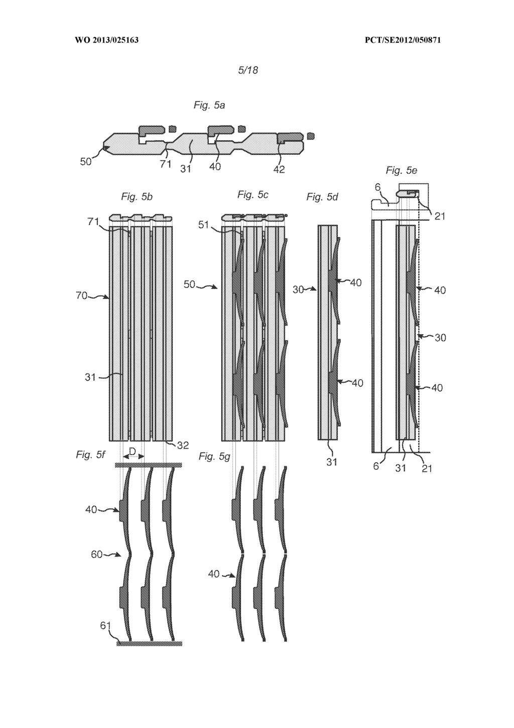
16 Figure 5a shows a cross section o f a tongue blank 5 0 comprising several displaceable tongues that comprise o f a main tongue body 3 1 and separate flexible parts 4 0 connected to the tongue body. Figure 5b shows a tongue body blank 7 0 comprising several tongue bodies 3 1 that are connected with tongue body rails 71. Such rails may for example b e formed by punching away material from the tongue bodies. Figure 5 f shows a spring part blank 6 0 where the spring parts are positioned with essentially the same distance D between each other a s the distance between the tongue bodies 31. This facilitates the fixing o f the spring parts to the tongue bodies since the spring parts may b e displaced after separation, shown in figure 5g, mainly parallel with the tongue bodies over the tongue bodies and pressed vertically such that the fixing connection part 42 enters the fixing groove 32. A tongue blank 5 0 may b e formed a s shown in figure 5c. Such forming may b e made a s a separate operation and tongue blanks are delivered a s integrated blanks. The connection may also b e made in line with the inserting o f the tongue into the displacement groove. The tongues 3 0 are separated from the blank a s shown in figure 5d and inserted into the displacement groove 2 1 a s shown in figure 5e. The tongues may b e inserted in a groove o f the strip panel comprising the strip or into a groove formed in the other adjacent panel. Figure 6a- 6d shows alternative methods to connect the spring parts 4 0 to a main tongue body 31. One or several holes 34a or cavities 34b may b e formed. Figure 6e shows that different lengths o f the displaceable tongues may b e formed by combining several spring parts that are positioned along the main tongue body 31. Figures 7a-7c show locking o f two panels 1,1'. Figure 7a shows that the tongue 3 0 tilts downwards during locking
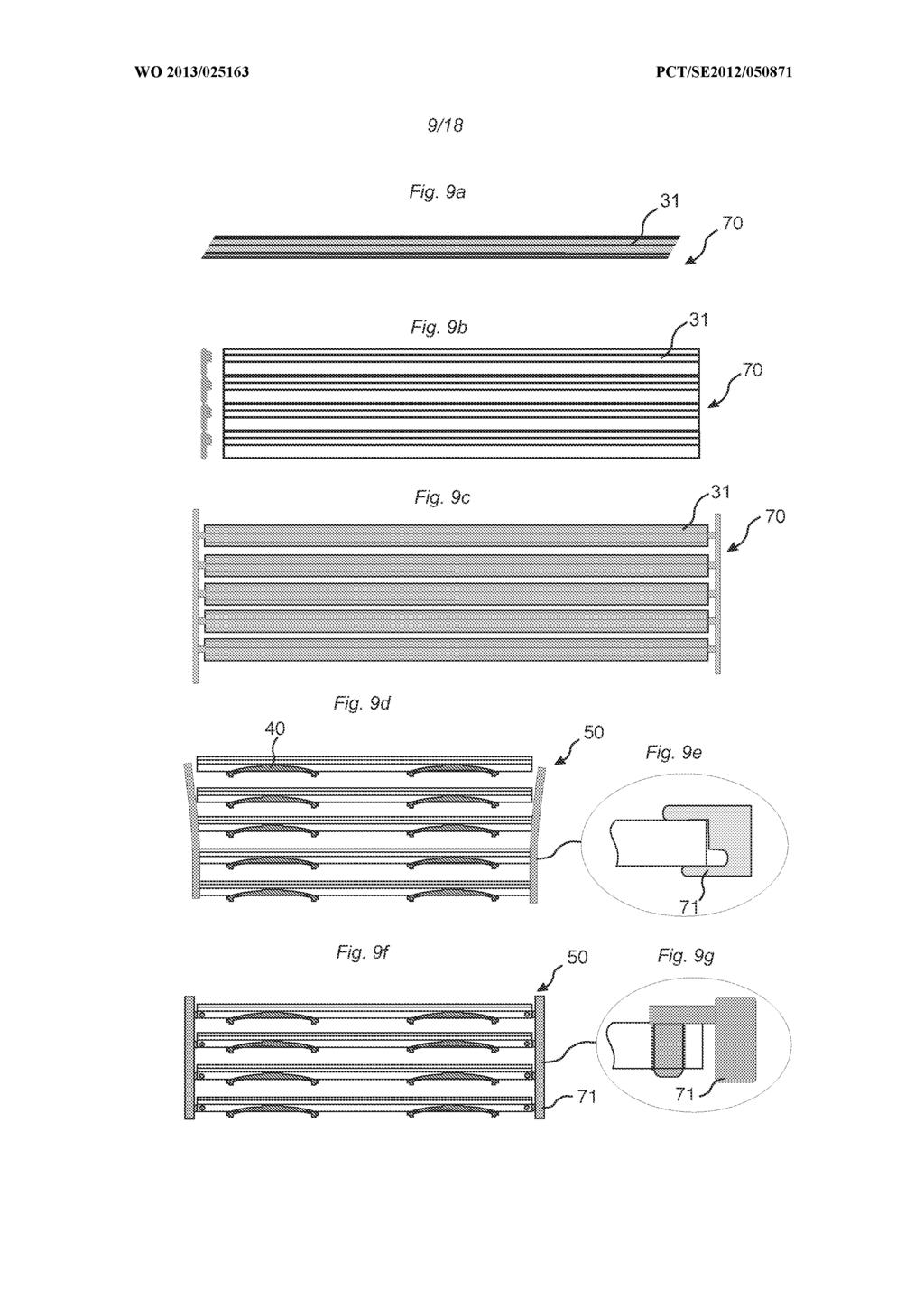
17 and figure 7c shows that the tongue 3 0 tilts upwards in locked position such that an outer part o f the rigid tongue body forms an upper contact surface 2 2 with the displacement groove 2 1 and that an inner part forms a lower contact surface 23. This means that it i s an advantage to connect the spring part to an upper part o f the main tongue body. The spring part may o f course b e connected to a lower part into a fixing groove that i s open downwards. Figures 8a - 8e shows a method to form and insert displaceable tongues into an edge o f a panel that may b e used for example when tongue bodies are delivered a s loose element or a s extruded sections that are cut into defined lengths. The tongue bodies 3 1 are displaced, for example, parallel with their lengths and spring part blanks 6 0 are displaced towards the tongue bodies where the spring parts 4 0 are separated and connected to the tongue body when the tongue body 3 1 i s displaced in its length direction. The displaceable tongues 3 0 are thereafter inserted into the displacement groove 21. Figures 9a -9c show that a tongue body blank may b e formed a s an extruded section, figure 9a, b, or by, for example, machining a panel from a machined wood, wood/plastic or plastic panel, figure 9b, or by injection moulding, figure 9c. Figure 9d and 9f show that tongue blanks may b e formed by displaceable tongues that are connected with rails that may b e comprise extrudes section, figure 9e, or moulded parts, figure 9g. Figures loa-lod show preferred embodiments o f displaceable tongues 30. Figure 10a shows overlapping spring parts 40. Figure 10b shows a spring part that i s glued to a tongue body. Figure 10c show spring parts with
18 a spring part body that i s only flexible at one edge. Figure lod shows spring parts that are connected to each other. Figure loe shows a tongue 3 0 with a spring part that i s connected into an inclined displacement groove 2 1 in the strip panel comprising the locking strip 6. Figure lof shows a displaceable tongue 3 0 inserted into an edge o f a groove panel comprising the locking groove 14. Figure log shows a locking system that only locks vertically. The strip 6 has no locking element. The horizontal locking may b e accomplished with for example friction between the long edges. Figures 11a - llg shows that the spring part may also b e formed from a flexible material such as, for example, rubber. The flexible parts are even in this embodiment positioned with a distance between each other along the main tongue body and the separate parts may b e compressed and displaced beyond the first vertical tongue plane Tpl a s shown in figure 11c. Preferably flexing cavities 3 3 are formed in the main tongue body to allow such compression. The spring parts 4 0 are preferably asymmetric in the length direction o f the displaceable tongue 30. Figures 12a - 12i show that several fixing cavities 3 3 and flexing cavities 3 4 may b e formed in the main tongue body 3 1 in order to fix spring parts and to allow compression or flexing displacement within beyond the vertical tongue plane Tpl. The figures show that the tongue bodies 3 1 and the spring parts 4 0 are asymmetric in the length direction o f the tongue. Figures 13a-13f show that also other parts o f the displaceable tongue may b e connected a s separate parts, for example, friction connection 3 6 that may b e attached
19 to a main tongue body 3 1 a s shown in figure 13d. Figure 13e shows that a friction connection 3 6 may b e formed and attached to the main tongue body 3 1 such that it may b e displaced with a turning. Such turning device may b e used a s a link in order to displace a tongue outwardly from the displacement groove when the tongue i s pushed sideways along the joint with a side pressure. Figures 14a-14d show an alternative method to form a displaceable tongue that comprises separate spring parts 40. The spring parts are inserted into the displacement groove 21. A main tongue body 3 1 i s thereafter inserted into the displacement groove and connected to the spring parts 40. Figures 15a-15f shows a preferred embodiment o f a spring part that i s suitable to b e inserted into a displacements groove 21. Figure 15a shows the spring part 4 0 from above and figure 15b i s a side view. The spring part comprises a frictions connection 36, a snapping connection 4 4 and a holding connection 45 located vertically at opposite upsides o f the spring part. The snapping and holding connections are displaced along the spring part body 41. The main tongue body 3 1 i s automatically snapped to the spring part that i s connected with the friction connection 3 6 to the displacement groove. Figure 15e and 15f shows cross sections during locking. The snapping connection 4 4 i s fixed to the main tongue body and the holding connections slides against the tongue body 3 1 during locking. The spring part 4 1 may o f course also b e attached to the main tongue body prior to the fixing into the displacement groove 21. Figures 16a-g shows a spring part 4 0 that i s only possible to snap to a main tongue body 3 1 when the spring part i s already in the displacement groove 2 1 since the spring part only comprises a snapping connection 4 4 and
20 no holding connection. Figure 16a shows the spring part seen from above and figure 16b shows a side view. It i s preferred that the snapping connection 4 4 i s located on the upper part o f the spring part 40. Figures 17a-g shows that a flexing cavity 3 3 may b e formed in the main tongue body 3 1 and this embodiment allows that a major part o f the spring part body 4 1 may b e displaced beyond the vertical tongue plane Tpl Figure 18a -18e shows that tongue body 3 1 may b e formed a s a three-dimensional moulded component and optimized to b e snapped to a spring part. The material savings are mainly obtained due to the fact that the plastic material o f the tongue body 3 1 may b e less costly since no flexibility i s required. Figure 18e i s a side view o f figure 18d. The spring part protrusions 46, 46', are during locking displaced in the displacement cavities 33, 33'. The described tongues are mainly intended to b e used on short edges o f panels comprising locking systems on long edges that may b e locked b y angling. However, the tongues may b e used on short and/or long edges. The principles o f the invention may also b e used to form two-piece tongues that are not flexible and that are, for example, used to b e displaced along the joint during locking. Separate parts may b e used as, for example, wedges that during displacement create a movement o f the tongue perpendicular to the edge.
21 CLAIMS 1. Building panels provided with a locking system for vertical locking o f a first (1) and a second building panel (1') by a vertical displacement o f said first and second building panel (1,1') relative each other, a displaceable tongue (30) i s attached into a sidewardly open displacement groove (21) provided at an edge o f the first building panel, said displaceable tongue cooperates with a tongue groove (20) provided at an adjacent edge o f the second building panel (1') for locking the edge and the adjacent edge vertically, a strip (6) protrudes: below the displacement groove and outwardly beyond the upper part o f the edge; or below the tongue groove and outwardly beyond the upper part o f the adjacent edge, c h a r a c t e r i s e d in that the displaceable tongue (30) comprises a main tongue body (31) extending along the edge o f the first building panel and separate flexible spring parts (40) attached to the main tongue body (31), and that the separate spring parts (40) are located in an inner part o f the displacement groove (21) and spaced from each other in the length direction o f the main tongue body (31). 2. The building panels a s claimed in claim 1, wherein the spring parts are asymmetric in a direction along the edge. 3. The building panels a s claimed in claim 1 or 2, wherein the main tongue body (31) and the spring parts (40) are made o f different materials. 4. The building panels a s claimed in any one o f the claims 1-3, wherein said tongue body (31) comprises an upwardly or downwardly open fixing groove (32).
22 5. The building panels a s claimed in any one o f claims 1-4, wherein said separate spring parts (40) comprise an upwardly or downwardly extending fixing connection part (42). 6. The building panels a s claimed in any one o f the claims 1-5, wherein said spring parts (40) during locking i s displaced or compressed horizontally beyond a vertical tongue plane Tpl that comprises the inner part o f the tongue body (30). 7. The building panels a s claimed in any one o f the claims 1-6, wherein said spring parts (40) are overlapping a part or the tongue body (30) during locking. 8. The building panels a s claimed in any one o f the claims 1-7, wherein said spring parts (40) are located in a vertically open flexing cavity (33) formed in the tongue body. 9. The building panels a s claimed in any one o f the claims 1-8, wherein said building panels are floor panels. 10. A tongue blank (50) comprising at least two tongues (30), which are each designed to b e inserted into a groove (21) o f a building panel and lock the building panel to an adjacent building panel, a part o f each tongue i s configured to b e displaced during locking c h a r a c t e r i s e d in that the tongues (30) are o f an elongated shape and that each tongue comprise a separate spring part (40) connected to a main body (31) o f the tongue.
23 11. The tongue blank (50) a s claimed in claim 10, wherein the spring part (40) i s asymmetric in the length direction o f the tongue. 12. The tongue blank (50) a s claimed in claim 1 0 or 11, wherein each tongue comprises two or more spring parts (40) that are spaced from each other in the length direction o f the tongue.
24
25
26
27
28
29
30
31
32
33
34
35
36
37
38
39
40
41
42 n erna ona app ca on o. PCT/SE201 2/ A. CLASSIFICATION OF SUBJECT MATTER IPC: see extra sheet According to International Patent Classification (IPC) or to both national classification and IPC B. FIELDS SEARCHED Minimum documentation searched (classification system followed by classification symbols) IPC: E04F Documentation searched other than minimum documentation to the extent that such documents are included in the fields searched SE, DK, Fl, NO classes as above Electronic data base consulted during the international search (name of data base and, where practicable, search terms used) EPO-lnternal, PAJ, WPI data C. DOCUMENTS CONSIDERED TO BE RELEVANT Category* Citation of document, with indication, where appropriate, of the relevant passages Relevant to claim No. X DE A 1 (FLOORING TECHNOLOGIES LTD), January 2009 ( ); paragraphs [0042], [0043]; figures 4a-b; Details 7,8 A W O A 1 (VAELINGE INNOVATION A B ET AL), April 2006 ( ); abstract; figures 7c,7d A WO A2 (SCHULTE GUIDO ET AL), 3 February ( ); page 17 ; figures 5a,5b; Detail 39 Further documents are listed in the continuation of Box C. See patent family annex. * Special categories of cited documents: " later document published after the international fding date or priority "A" document defining the general state of the art which is not considered date and not in conflict with the application but cited to understand to be of particular relevance the principle or theory underlying the invention "E" earlier application or patent but published on or after the international 'X" document of particular relevance; the claimed invention cannot be filing date considered novel or cannot be considered to involve an inventive "L" document which may throw doubts on priority claim(s) or which is step when the document is taken alone cited to establish the publication date of another citation or other Ύ " document of particular relevance; the claimed invention cannot be special reason (as specified) considered to involve an inventive step when the document is "O" document referring to an oral disclosure, use, exhibition or other combined with one or more other such documents, such combination means being obvious to a person skilled in the art "P" document published prior to the international filing date but later than ' '&" document member of the same patent family the priority date claimed Date of the actual completion of the international search Date of mailing of the international search report Name and mailing address of the ISA/SE Patent- och registreringsverket Box 5055 Authorized officer Orjan Nylund S STOCKHOLM Facsimile No Telephone No Form PCT/ISA/210 (second sheet) (July 2009)
43 n erna ona app ca on o. PCT/SE201 2/ C (Continuation). DOCUMENTS CONSIDERED TO BE RELEVANT Category* Citation of document, with indication, where appropriate, of the relevant passages Relevant to claim No. A DE A 1 (HAMBERGER INDUSTRIEWERKE 1-9 GMBH), 19 February 2009 ( ); abstract; figures 4-7; Details 43,46 A WO A 1 (VALINGE ALUMINIUM A B ET AL), October 2003 ( ); abstract; page 40, line line 24; figure 35a; Detail 70 P, X Pervan, Darco, VA069 Combi Tongue, September 13, 201 1, 1-9 ISSN , IP.com number: IPCOM D. Retrieved from: Epoquenet; Database XPIPCOM, Accession number AN XP Form PCT/ISA/210 (continuation of second sheet) (July 2009)
44 n erna ona app ca on o. PCT/SE201 2/ Box No. II Observations where certain claims were found unsearchable (Continuation of item 2 of first sheet) This international search report has not been established in respect of certain claims under Article 17(2)(a) for the following Claims Nos.: because they relate to subject matter not required to be searched by this Authority, namely: Claims Nos.: because they relate to parts of the international application that do not comply with the prescribed requirements to such an extent that no meaningful international search can be carried out, specifically: Claims Nos.: because they are dependent claims and are not drafted in accordance with the second and third sentences of Rule 6.4(a). Box No. Ill Observations where unity of invention is lacking (Continuation of item 3 of first sheet) This International Searching Authority found multiple inventions in this international application, as follows: 1: Claims 1-9 directed to a building panel provided with a locking system. 2 : Claims directed to a tongue blank (50) comprising at least two tongues. As all required additional search fees were timely paid by the applicant, this international search report covers all searchable claims. As all searchable claims could be searched without effort justifying additional fees, this Authority did not invite payment of additional fees. As only some of the required additional search fees were timely paid by the applicant, this international search report covers only those claims for which fees were paid, specifically claims Nos.: No required additional search fees were timely paid by the applicant. Consequently, this international search report restricted to the invention first mentioned in the claims; it is covered by claims Nos.: 1-9 Form PCT/ISA/210 (continuation of first sheet (2)) (July 2009) The additional search fees were accompanied by the applicant' s protest and, where applicable, the payment of a protest fee. The additional search fees were accompanied by the applicant's protest but the applicable protest fee was not paid within the time limit specified in the invitation. No protest accompanied the payment of additional search fees.
45 n erna ona app ca on o. PCT/SE201 2/ Continuation of: second sheet International Patent Classification (IPC) E04F 75/02 ( ) E04F 75/04 ( ) Form PCT/ISA/210 (extra sheet) (July 2009)
46 n erna ona app ca on o. Information on patent family members PCT/SE201 2/ DE A 1 15/01/2009 NONE Form PCT/ISA/210 (patent family annex) (July 2009)
47 n erna ona app ca on o. Information on patent family members PCT/SE201 2/ O A 1 AT T 15/1 2/201 1 AT T 15/01/2008 AT T 15/02/201 2 Form PCT/ISA/210 (patent family annex) (July 2009) A U A 1 27/04/2006 BR PI A 02/09/2008 CA A 1 27/04/2006 CN A 26/09/2007 CN C 07/1 0/2009 CN A 31/03/201 0 DE U 1 16/07/2009 DE U 1 30/09/201 0 DE U 1 23/09/201 0 DE T3 07/07/201 1 DE U 1 05/01/201 1 DK T4 28/02/201 1 DK T3 14/05/201 2 DK T3 19/03/201 2 EP A2 30/1 1/201 1 EP A2 23/1 1/201 1 EP A2 23/1 1/201 1 EP A2 23/1 1/201 1 EP A2 23/1 1/201 1 EP A2 23/1 1/201 1 EP A2 23/1 1/201 1 EP A2 23/1 1/201 1 EP A2 23/1 1/201 1 EP A2 23/1 1/201 1 EP A2 23/1 1/201 1 EP A2 23/1 1/201 1 EP A2 23/1 1/201 1 EP A2 23/1 1/201 1 EP A2 23/1 1/201 1 EP A2 23/1 1/201 1 EP A2 23/1 1/201 1 EP A2 23/1 1/201 1 EP A2 09/1 1/201 1 EP A2 09/1 1/201 1 EP A2 19/1 0/201 1 EP A2 19/1 0/201 1 EP A2 19/1 0/201 1 EP A2 09/02/201 1 EP A2 26/01/201 1 ES T3 11/04/201 2
48 n erna ona app ca on o. Information on patent family members PCT/SE201 2/ O A2 03/02/201 1 CN A 30/05/201 2 DE A 1 17/02/201 1 EP A2 06/06/201 2 US A 1 24/05/201 2 DE A 1 19/02/2009 EP A 1 15/09/201 0 O A 1 19/02/2009 WO A 1 09/1 0/2003 AT T 15/05/201 0 A U A 1 13/1 0/2003 BR A 01/02/2005 CA C 10/01/201 2 CN A 17/08/2005 CN C 31/1 2/2008 DE D 1 17/06/201 0 EP A3 25/07/201 2 EP A3 30/1 1/201 1 EP A3 30/1 1/201 1 EP A3 26/1 0/201 1 EP B 1 05/05/201 0 IL A 01/09/2009 J P B2 02/06/201 0 J P A 21/07/2005 NO A 02/1 2/2004 NZ A 28/07/2006 PL A 1 11/07/2005 PL B 1 29/06/201 2 RU A 10/06/2005 RU C2 10/07/2007 UA C2 10/1 2/2007 US B2 29/1 2/2009 US A 1 28/07/2005 US B2 30/1 1/201 0 US B2 20/07/201 0 US B2 16/03/201 0 US A 1 11/09/2008 US A 1 11/09/2008 US A 1 21/02/2008 US A 1 06/04/2006 Form PCT/ISA/210 (patent family annex) (July 2009)
WO 2008/ A3 PCT. (19) World Intellectual Property Organization International Bureau
 World Intellectual Property Organization International Bureau") (12) INTERNATIONAL APPLICATION PUBLISHED UNDER THE PATENT COOPERATION TREATY (PCT) (19) World Intellectual Property Organization International Bureau (43) International Publication Date (10) International
(12) INTERNATIONAL APPLICATION PUBLISHED UNDER THE PATENT COOPERATION TREATY (PCT) (19) World Intellectual Property Organization International Bureau (43) International Publication Date (10) International
(10) International Publication Number (43) International Publication Date 9 January 2014 ( ) P O P C T
 International Publication Number (43) International Publication Date 9 January 2014 ( ) P O P C T") (12) INTERNATIONAL APPLICATION PUBLISHED UNDER THE PATENT COOPERATION TREATY (PCT) (19) World Intellectual Property Organization International Bureau (10) International Publication Number (43) International
(12) INTERNATIONAL APPLICATION PUBLISHED UNDER THE PATENT COOPERATION TREATY (PCT) (19) World Intellectual Property Organization International Bureau (10) International Publication Number (43) International
WO 2007/ Al PCT. (19) World Intellectual Property Organization International Bureau
 World Intellectual Property Organization International Bureau") (12) INTERNATIONAL APPLICATION PUBLISHED UNDER THE PATENT COOPERATION TREATY (PCT) (19) World Intellectual Property Organization International Bureau (43) International Publication Date (10) International
(12) INTERNATIONAL APPLICATION PUBLISHED UNDER THE PATENT COOPERATION TREATY (PCT) (19) World Intellectual Property Organization International Bureau (43) International Publication Date (10) International
GM, KE, LR, LS, MW, MZ, NA, RW, SD, SL, SZ, TZ, PANY [US/US]; 1500 City West Boulevard, Suite 800,
![GM, KE, LR, LS, MW, MZ, NA, RW, SD, SL, SZ, TZ, PANY [US/US]; 1500 City West Boulevard, Suite 800,](/thumbs/93/114408396.jpg "GM, KE, LR, LS, MW, MZ, NA, RW, SD, SL, SZ, TZ, PANY [US/US]; 1500 City West Boulevard, Suite 800,") (12) INTERNATIONAL APPLICATION PUBLISHED UNDER THE PATENT COOPERATION TREATY (PCT) (19) World Intellectual Property Organization International Bureau (10) International Publication Number (43) International
(12) INTERNATIONAL APPLICATION PUBLISHED UNDER THE PATENT COOPERATION TREATY (PCT) (19) World Intellectual Property Organization International Bureau (10) International Publication Number (43) International
Time allowed TWO hours plus 15 minutes reading time
 ICPA: Introductory Certificate in Patent Administration Mock Examination 2017/18 Course Time: as agreed with your mentor INSTRUCTIONS TO CANDIDATES This examination pack comprises: Time allowed TWO hours
(10) International Publication Number (43) International Publication Date
 International Publication Number (43) International Publication Date") (12) INTERNATIONAL APPLICATION PUBLISHED UNDER THE PATENT COOPERATION TREATY (PCT) (19) World Intellectual Property Organization International Bureau (10) International Publication Number (43) International
(12) INTERNATIONAL APPLICATION PUBLISHED UNDER THE PATENT COOPERATION TREATY (PCT) (19) World Intellectual Property Organization International Bureau (10) International Publication Number (43) International
WO 2014/ Al P O P C T. 30 May 2014 ( )
") (12) INTERNATIONAL APPLICATION PUBLISHED UNDER THE PATENT COOPERATION TREATY (PCT) (19) World Intellectual Property Organization International Bureau (10) International Publication Number (43) International
(12) INTERNATIONAL APPLICATION PUBLISHED UNDER THE PATENT COOPERATION TREATY (PCT) (19) World Intellectual Property Organization International Bureau (10) International Publication Number (43) International
2 December 2010 ( ) WO 2010/ Al
 WO 2010/ Al") (12) INTERNATIONAL APPLICATION PUBLISHED UNDER THE PATENT COOPERATION TREATY (PCT) (19) World Intellectual Property Organization International Bureau (43) International Publication Date (10) International
(12) INTERNATIONAL APPLICATION PUBLISHED UNDER THE PATENT COOPERATION TREATY (PCT) (19) World Intellectual Property Organization International Bureau (43) International Publication Date (10) International
(54) Title: APPARATUS INCLUDING STRAIN GAUGES FOR ESTIMATING DOWNHOLE STRING PARAMETERS
 Title: APPARATUS INCLUDING STRAIN GAUGES FOR ESTIMATING DOWNHOLE STRING PARAMETERS") (12) INTERNATIONAL APPLICATION PUBLISHED UNDER THE PATENT COOPERATION TREATY (PCT) (19) World Intellectual Property Organization International Bureau (10) International Publication Number (43) International
(12) INTERNATIONAL APPLICATION PUBLISHED UNDER THE PATENT COOPERATION TREATY (PCT) (19) World Intellectual Property Organization International Bureau (10) International Publication Number (43) International
PCT WO 2008/ A2
 (12) INTERNATIONAL APPLICATION PUBLISHED UNDER THE PATENT COOPERATION TREATY (PCT) (19) World Intellectual Property Organization International Bureau (43) International Publication Date (10) International
(12) INTERNATIONAL APPLICATION PUBLISHED UNDER THE PATENT COOPERATION TREATY (PCT)
 INTERNATIONAL APPLICATION PUBLISHED UNDER THE PATENT COOPERATION TREATY (PCT)") (12) INTERNATIONAL APPLICATION PUBLISHED UNDER THE PATENT COOPERATION TREATY (PCT) (19) World Intellectual Property Organization International Bureau (10) International Publication Number (43) International
(12) INTERNATIONAL APPLICATION PUBLISHED UNDER THE PATENT COOPERATION TREATY (PCT) (19) World Intellectual Property Organization International Bureau (10) International Publication Number (43) International
1 September 2011 ( ) 2U11/1U4712 A l
 2U11/1U4712 A l") (12) INTERNATIONAL APPLICATION PUBLISHED UNDER THE PATENT COOPERATION TREATY (PCT) (19) World Intellectual Property Organization International Bureau (10) International Publication Number (43) International
(12) INTERNATIONAL APPLICATION PUBLISHED UNDER THE PATENT COOPERATION TREATY (PCT) (19) World Intellectual Property Organization International Bureau (10) International Publication Number (43) International
(10) International Publication Number (43) International Publication Date
 International Publication Number (43) International Publication Date") (12) INTERNATIONAL APPLICATION PUBLISHED UNDER THE PATENT COOPERATION TREATY (PCT) (19) World Intellectual Property Organization International Bureau (10) International Publication Number (43) International
(12) INTERNATIONAL APPLICATION PUBLISHED UNDER THE PATENT COOPERATION TREATY (PCT) (19) World Intellectual Property Organization International Bureau (10) International Publication Number (43) International
WO 2015/ A3. 10 December 2015 ( ) P O P C T FIG. 1. [Continued on nextpage]
![WO 2015/ A3. 10 December 2015 ( ) P O P C T FIG. 1. [Continued on nextpage]](/thumbs/92/110981145.jpg "WO 2015/ A3. 10 December 2015 ( ) P O P C T FIG. 1. [Continued on nextpage]") (12) INTERNATIONAL APPLICATION PUBLISHED UNDER THE PATENT COOPERATION TREATY (PCT) (19) World Intellectual Property Organization International Bureau (10) International Publication Number (43) International
(12) INTERNATIONAL APPLICATION PUBLISHED UNDER THE PATENT COOPERATION TREATY (PCT) (19) World Intellectual Property Organization International Bureau (10) International Publication Number (43) International
(10) International Publication Number (43) International Publication Date P O P C T
 International Publication Number (43) International Publication Date P O P C T") (12) INTERNATIONAL APPLICATION PUBLISHED UNDER THE PATENT COOPERATION TREATY (PCT) (19) World Intellectual Property Organization International Bureau (10) International Publication Number (43) International
(12) INTERNATIONAL APPLICATION PUBLISHED UNDER THE PATENT COOPERATION TREATY (PCT) (19) World Intellectual Property Organization International Bureau (10) International Publication Number (43) International
upon receipt of that report (Rule 48.2(g)) Fig. I a
) Fig. I a") (12) INTERNATIONAL APPLICATION PUBLISHED UNDER THE PATENT COOPERATION TREATY (PCT) (19) World Intellectual Property Organization International Bureau (43) International Publication Date (10) International
(12) INTERNATIONAL APPLICATION PUBLISHED UNDER THE PATENT COOPERATION TREATY (PCT) (19) World Intellectual Property Organization International Bureau (43) International Publication Date (10) International
EP A1 (19) (11) EP A1 (12) EUROPEAN PATENT APPLICATION. (43) Date of publication: Bulletin 2012/33
 (11) EP A1 (12) EUROPEAN PATENT APPLICATION. (43) Date of publication: Bulletin 2012/33") (19) (12) EUROPEAN PATENT APPLICATION (11) EP 2 486 833 A1 (43) Date of publication: 15.08.2012 Bulletin 2012/33 (51) Int Cl.: A47J 43/07 (2006.01) A47J 43/046 (2006.01) (21) Application number: 11250148.1
(19) (12) EUROPEAN PATENT APPLICATION (11) EP 2 486 833 A1 (43) Date of publication: 15.08.2012 Bulletin 2012/33 (51) Int Cl.: A47J 43/07 (2006.01) A47J 43/046 (2006.01) (21) Application number: 11250148.1
(19) World Intellectual Property Organization International Bureau
 World Intellectual Property Organization International Bureau") (12) INTERNATIONAL APPLICATION PUBLISHED UNDER THE PATENT COOPERATION TREATY (PCT) (19) World Intellectual Property Organization International Bureau (43) International Publication Date (10) International
(12) INTERNATIONAL APPLICATION PUBLISHED UNDER THE PATENT COOPERATION TREATY (PCT) (19) World Intellectual Property Organization International Bureau (43) International Publication Date (10) International
WO 2008/ Al. (19) World Intellectual Property Organization International Bureau
 World Intellectual Property Organization International Bureau") (12) INTERNATIONAL APPLICATION PUBLISHED UNDER THE PATENT COOPERATION TREATY (PCT) (19) World Intellectual Property Organization International Bureau (43) International Publication Date (10) International
(12) INTERNATIONAL APPLICATION PUBLISHED UNDER THE PATENT COOPERATION TREATY (PCT) (19) World Intellectual Property Organization International Bureau (43) International Publication Date (10) International
WO 2017/ Al. 24 August 2017 ( ) P O P C T
 P O P C T") (12) INTERNATIONAL APPLICATION PUBLISHED UNDER THE PATENT COOPERATION TREATY (PCT) (19) World Intellectual Property Organization International Bureau (10) International Publication Number (43) International
(12) INTERNATIONAL APPLICATION PUBLISHED UNDER THE PATENT COOPERATION TREATY (PCT) (19) World Intellectual Property Organization International Bureau (10) International Publication Number (43) International
TEPZZ 7545 A_T EP A1 (19) (11) EP A1 (12) EUROPEAN PATENT APPLICATION. (43) Date of publication: Bulletin 2014/29
 (11) EP A1 (12) EUROPEAN PATENT APPLICATION. (43) Date of publication: Bulletin 2014/29") (19) TEPZZ 74 A_T (11) EP 2 74 11 A1 (12) EUROPEAN PATENT APPLICATION (43) Date of publication: 16.07.14 Bulletin 14/29 (21) Application number: 1476.7 (1) Int Cl.: B21F 27/ (06.01) B21C 1/02 (06.01) C21D
(19) TEPZZ 74 A_T (11) EP 2 74 11 A1 (12) EUROPEAN PATENT APPLICATION (43) Date of publication: 16.07.14 Bulletin 14/29 (21) Application number: 1476.7 (1) Int Cl.: B21F 27/ (06.01) B21C 1/02 (06.01) C21D
* Bitstream Bitstream Renderer encoder decoder Decoder
 (12) INTERNATIONAL APPLICATION PUBLISHED UNDER THE PATENT COOPERATION TREATY (PCT) (19) World Intellectual Property Organization International Bureau (10) International Publication Number (43) International
EP A1 (19) (11) EP A1 (12) EUROPEAN PATENT APPLICATION. (43) Date of publication: Bulletin 2011/40
 (11) EP A1 (12) EUROPEAN PATENT APPLICATION. (43) Date of publication: Bulletin 2011/40") (19) (12) EUROPEAN PATENT APPLICATION (11) EP 2 372 845 A1 (43) Date of publication: 05.10.2011 Bulletin 2011/40 (51) Int Cl.: H01R 11/28 (2006.01) (21) Application number: 10425105.3 (22) Date of filing:
(19) (12) EUROPEAN PATENT APPLICATION (11) EP 2 372 845 A1 (43) Date of publication: 05.10.2011 Bulletin 2011/40 (51) Int Cl.: H01R 11/28 (2006.01) (21) Application number: 10425105.3 (22) Date of filing:
o o WO 2013/ Al 3 January 2013 ( ) P O P C T
 P O P C T") (12) INTERNATIONAL APPLICATION PUBLISHED UNDER THE PATENT COOPERATION TREATY (PCT) (19) World Intellectual Property Organization International Bureau (10) International Publication Number (43) International
(12) INTERNATIONAL APPLICATION PUBLISHED UNDER THE PATENT COOPERATION TREATY (PCT) (19) World Intellectual Property Organization International Bureau (10) International Publication Number (43) International
(12) INTERNATIONAL APPLICATION PUBLISHED UNDER THE PATENT COOPERATION TREATY (PCT)
 INTERNATIONAL APPLICATION PUBLISHED UNDER THE PATENT COOPERATION TREATY (PCT)") (12) INTERNATIONAL APPLICATION PUBLISHED UNDER THE PATENT COOPERATION TREATY (PCT) (19) World Intellectual Property Organization International Bureau (10) International Publication Number (43) International
(12) INTERNATIONAL APPLICATION PUBLISHED UNDER THE PATENT COOPERATION TREATY (PCT) (19) World Intellectual Property Organization International Bureau (10) International Publication Number (43) International
WO 2016/ Al. 25 February 2016 ( ) P O P C T. kind of regional protection available): ARIPO (BW, GH, [Continued on next page]
![WO 2016/ Al. 25 February 2016 ( ) P O P C T. kind of regional protection available): ARIPO (BW, GH, [Continued on next page]](/thumbs/88/115482596.jpg "WO 2016/ Al. 25 February 2016 ( ) P O P C T. kind of regional protection available): ARIPO (BW, GH, [Continued on next page]") (12) INTERNATIONAL APPLICATION PUBLISHED UNDER THE PATENT COOPERATION TREATY (PCT) (19) World Intellectual Property Organization International Bureau (10) International Publication Number (43) International
(12) INTERNATIONAL APPLICATION PUBLISHED UNDER THE PATENT COOPERATION TREATY (PCT) (19) World Intellectual Property Organization International Bureau (10) International Publication Number (43) International
I International Bureau (10) International Publication Number (43) International Publication Date
 International Publication Number (43) International Publication Date") (12) INTERNATIONAL APPLICATION PUBLISHED UNDER THE PATENT COOPERATION TREATY (PCT) (19) World Intellectual Property Organization I International Bureau (10) International Publication Number (43) International
(12) INTERNATIONAL APPLICATION PUBLISHED UNDER THE PATENT COOPERATION TREATY (PCT) (19) World Intellectual Property Organization I International Bureau (10) International Publication Number (43) International
EP A1 (19) (11) EP A1 (12) EUROPEAN PATENT APPLICATION. (43) Date of publication: Bulletin 2010/31
 (11) EP A1 (12) EUROPEAN PATENT APPLICATION. (43) Date of publication: Bulletin 2010/31") (19) (12) EUROPEAN PATENT APPLICATION (11) EP 2 213 476 A1 (43) Date of publication: 04.08.2010 Bulletin 2010/31 (21) Application number: 09151785.4 (51) Int Cl.: B44C 5/04 (2006.01) E04F 13/00 (2006.01)
(19) (12) EUROPEAN PATENT APPLICATION (11) EP 2 213 476 A1 (43) Date of publication: 04.08.2010 Bulletin 2010/31 (21) Application number: 09151785.4 (51) Int Cl.: B44C 5/04 (2006.01) E04F 13/00 (2006.01)
WO 2017/ Al. 12 October 2017 ( ) P O P C T
 P O P C T") (12) INTERNATIONAL APPLICATION PUBLISHED UNDER THE PATENT COOPERATION TREATY (PCT) (19) World Intellectual Property Organization International Bureau (10) International Publication Number (43) International
(12) INTERNATIONAL APPLICATION PUBLISHED UNDER THE PATENT COOPERATION TREATY (PCT) (19) World Intellectual Property Organization International Bureau (10) International Publication Number (43) International
(12) INTERNATIONAL APPLICATION PUBLISHED UNDER THE PATENT COOPERATION TREATY (PCT)
 INTERNATIONAL APPLICATION PUBLISHED UNDER THE PATENT COOPERATION TREATY (PCT)") (12) INTERNATIONAL APPLICATION PUBLISHED UNDER THE PATENT COOPERATION TREATY (PCT) (19) World Intellectual Property Organization International Bureau (10) International Publication Number (43) International
(12) INTERNATIONAL APPLICATION PUBLISHED UNDER THE PATENT COOPERATION TREATY (PCT) (19) World Intellectual Property Organization International Bureau (10) International Publication Number (43) International
as to applicant's entitlement to apply for and be granted a
 (12) INTERNATIONAL APPLICATION PUBLISHED UNDER THE PATENT COOPERATION TREATY (PCT) (19) World Intellectual Property Organization International Bureau (10) International Publication Number (43) International
Published: with international search report (Art. 21(3))
)") ma l (12) INTERNATIONAL APPLICATION PUBLISHED UNDER THE PATENT COOPERATION TREATY (PCT) (19) World Intellectual Property Organization International Bureau (10) International Publication Number (43) International
ma l (12) INTERNATIONAL APPLICATION PUBLISHED UNDER THE PATENT COOPERATION TREATY (PCT) (19) World Intellectual Property Organization International Bureau (10) International Publication Number (43) International
(10) International Publication Number (43) International Publication Date P C T P O
 International Publication Number (43) International Publication Date P C T P O") (12) INTERNATIONAL APPLICATION PUBLISHED UNDER THE PATENT COOPERATION TREATY (PCT) (19) World Intellectual Property Organization International Bureau (10) International Publication Number (43) International
(12) INTERNATIONAL APPLICATION PUBLISHED UNDER THE PATENT COOPERATION TREATY (PCT) (19) World Intellectual Property Organization International Bureau (10) International Publication Number (43) International
(43) International Publication Date (10) International Publication Number 22 November 2001 ( ) PCT w A1
 International Publication Date (10) International Publication Number 22 November 2001 ( ) PCT w A1") (12) INTERNATIONAL APPLICATION PUBLISHED UNDER THE PATENT COOPERATION TREATY (PCT) (19) World Intellectual Property Organization International Bureau 111111 1111111111 11111111111 1 111 11111111111111111111111
(12) INTERNATIONAL APPLICATION PUBLISHED UNDER THE PATENT COOPERATION TREATY (PCT) (19) World Intellectual Property Organization International Bureau 111111 1111111111 11111111111 1 111 11111111111111111111111
I International Bureau (10) International Publication Number (43) International Publication Date
 International Publication Number (43) International Publication Date") (12) INTERNATIONAL APPLICATION PUBLISHED UNDER THE PATENT COOPERATION TREATY (PCT) (19) World Intellectual Property Organization I International Bureau (10) International Publication Number (43) International
(12) INTERNATIONAL APPLICATION PUBLISHED UNDER THE PATENT COOPERATION TREATY (PCT) (19) World Intellectual Property Organization I International Bureau (10) International Publication Number (43) International
PCT WO 2007/ A2
 (12) INTERNATIONAL APPLICATION PUBLISHED UNDER THE PATENT COOPERATION TREATY (PCT) (19) World Intellectual Property Organization International Bureau (43) International Publication Date (10) International
EP A1 (19) (11) EP A1 (12) EUROPEAN PATENT APPLICATION. (43) Date of publication: Bulletin 2010/50
 (11) EP A1 (12) EUROPEAN PATENT APPLICATION. (43) Date of publication: Bulletin 2010/50") (19) (12) EUROPEAN PATENT APPLICATION (11) EP 2 261 890 A1 (43) Date of publication: 15.12.20 Bulletin 20/50 (51) Int Cl.: GD 13/02 (2006.01) GH 3/14 (2006.01) (21) Application number: 160308.2 (22) Date
(19) (12) EUROPEAN PATENT APPLICATION (11) EP 2 261 890 A1 (43) Date of publication: 15.12.20 Bulletin 20/50 (51) Int Cl.: GD 13/02 (2006.01) GH 3/14 (2006.01) (21) Application number: 160308.2 (22) Date
WO 2008/ Al PCT. (19) World Intellectual Property Organization International Bureau
 World Intellectual Property Organization International Bureau") (12) INTERNATIONAL APPLICATION PUBLISHED UNDER THE PATENT COOPERATION TREATY (PCT) (19) World Intellectual Property Organization International Bureau (43) International Publication Date (10) International
(12) INTERNATIONAL APPLICATION PUBLISHED UNDER THE PATENT COOPERATION TREATY (PCT) (19) World Intellectual Property Organization International Bureau (43) International Publication Date (10) International
TEPZZ A_T EP A1 (19) (11) EP A1 (12) EUROPEAN PATENT APPLICATION. (51) Int Cl.: B29B 15/12 ( ) B32B 5/26 (2006.
 (11) EP A1 (12) EUROPEAN PATENT APPLICATION. (51) Int Cl.: B29B 15/12 ( ) B32B 5/26 (2006.") (19) TEPZZ A_T (11) EP 3 112 111 A1 (12) EUROPEAN PATENT APPLICATION (43) Date of publication: 04.01.2017 Bulletin 2017/01 (1) Int Cl.: B29B 1/12 (2006.01) B32B /26 (2006.01) (21) Application number: 117028.8
(19) TEPZZ A_T (11) EP 3 112 111 A1 (12) EUROPEAN PATENT APPLICATION (43) Date of publication: 04.01.2017 Bulletin 2017/01 (1) Int Cl.: B29B 1/12 (2006.01) B32B /26 (2006.01) (21) Application number: 117028.8
TEPZZ Z47794A_T EP A1 (19) (11) EP A1. (12) EUROPEAN PATENT APPLICATION published in accordance with Art.
 (11) EP A1. (12) EUROPEAN PATENT APPLICATION published in accordance with Art.") (19) TEPZZ Z47794A_T (11) EP 3 047 794 A1 (12) EUROPEAN PATENT APPLICATION published in accordance with Art. 13(4) EPC (43) Date of publication: 27.07.16 Bulletin 16/ (21) Application number: 1478031.1
(19) TEPZZ Z47794A_T (11) EP 3 047 794 A1 (12) EUROPEAN PATENT APPLICATION published in accordance with Art. 13(4) EPC (43) Date of publication: 27.07.16 Bulletin 16/ (21) Application number: 1478031.1
EP A1 (19) (11) EP A1 (12) EUROPEAN PATENT APPLICATION. (43) Date of publication: Bulletin 2010/51
 (11) EP A1 (12) EUROPEAN PATENT APPLICATION. (43) Date of publication: Bulletin 2010/51") (19) (12) EUROPEAN PATENT APPLICATION (11) EP 2 263 736 A1 (43) Date of publication: 22.12.2010 Bulletin 2010/51 (51) Int Cl.: A61M 25/09 (2006.01) (21) Application number: 10165921.7 (22) Date of filing:
(19) (12) EUROPEAN PATENT APPLICATION (11) EP 2 263 736 A1 (43) Date of publication: 22.12.2010 Bulletin 2010/51 (51) Int Cl.: A61M 25/09 (2006.01) (21) Application number: 10165921.7 (22) Date of filing:
WO 2009/ Al PCT. (19) World Intellectual Property Organization International Bureau
 World Intellectual Property Organization International Bureau") (12) INTERNATIONAL APPLICATION PUBLISHED UNDER THE PATENT COOPERATION TREATY (PCT) (19) World Intellectual Property Organization International Bureau (43) International Publication Date (10) International
(12) INTERNATIONAL APPLICATION PUBLISHED UNDER THE PATENT COOPERATION TREATY (PCT) (19) World Intellectual Property Organization International Bureau (43) International Publication Date (10) International
TEPZZ 9_Z47 A_T EP A1 (19) (11) EP A1 (12) EUROPEAN PATENT APPLICATION. (43) Date of publication: Bulletin 2015/35
 (11) EP A1 (12) EUROPEAN PATENT APPLICATION. (43) Date of publication: Bulletin 2015/35") (19) TEPZZ 9_Z47 A_T (11) EP 2 9 473 A1 (12) EUROPEAN PATENT APPLICATION (43) Date of publication: 26.08.1 Bulletin 1/3 (21) Application number: 13836.0 (22) Date of filing: 04.02.1 (1) Int Cl.: B6B 9/093
(19) TEPZZ 9_Z47 A_T (11) EP 2 9 473 A1 (12) EUROPEAN PATENT APPLICATION (43) Date of publication: 26.08.1 Bulletin 1/3 (21) Application number: 13836.0 (22) Date of filing: 04.02.1 (1) Int Cl.: B6B 9/093
PCT WO 2007/ Al
 (12) INTERNATIONAL APPLICATION PUBLISHED UNDER THE PATENT COOPERATION TREATY (PCT) (19) World Intellectual Property Organization International Bureau (43) International Publication Date (10) International
TEPZZ 9746 A_T EP A1 (19) (11) EP A1 (12) EUROPEAN PATENT APPLICATION. (51) Int Cl.: A41F 1/00 ( )
 (11) EP A1 (12) EUROPEAN PATENT APPLICATION. (51) Int Cl.: A41F 1/00 ( )") (19) TEPZZ 9746 A_T (11) EP 2 974 611 A1 (12) EUROPEAN PATENT APPLICATION (43) Date of publication: 20.01.2016 Bulletin 2016/03 (51) Int Cl.: A41F 1/00 (2006.01) (21) Application number: 15159454.6 (22)
(19) TEPZZ 9746 A_T (11) EP 2 974 611 A1 (12) EUROPEAN PATENT APPLICATION (43) Date of publication: 20.01.2016 Bulletin 2016/03 (51) Int Cl.: A41F 1/00 (2006.01) (21) Application number: 15159454.6 (22)
TEPZZ _ 59 _A_T EP A1 (19) (11) EP A1 (12) EUROPEAN PATENT APPLICATION. (43) Date of publication: Bulletin 2017/09
 (11) EP A1 (12) EUROPEAN PATENT APPLICATION. (43) Date of publication: Bulletin 2017/09") (19) TEPZZ _ 59 _A_T (11) EP 3 135 931 A1 (12) EUROPEAN PATENT APPLICATION (43) Date of publication: 01.03.2017 Bulletin 2017/09 (51) Int Cl.: F16C 29/06 (2006.01) (21) Application number: 16190648.2 (22)
(19) TEPZZ _ 59 _A_T (11) EP 3 135 931 A1 (12) EUROPEAN PATENT APPLICATION (43) Date of publication: 01.03.2017 Bulletin 2017/09 (51) Int Cl.: F16C 29/06 (2006.01) (21) Application number: 16190648.2 (22)
TEPZZ 7 Z_ 4A T EP A2 (19) (11) EP A2 (12) EUROPEAN PATENT APPLICATION. (51) Int Cl.: G06F 3/0488 ( ) G06F 3/0482 (2013.
 (11) EP A2 (12) EUROPEAN PATENT APPLICATION. (51) Int Cl.: G06F 3/0488 ( ) G06F 3/0482 (2013.") (19) TEPZZ 7 Z_ 4A T (11) EP 2 720 134 A2 (12) EUROPEAN PATENT APPLICATION (43) Date of publication: 16.04.2014 Bulletin 2014/16 (51) Int Cl.: G06F 3/0488 (2013.01) G06F 3/0482 (2013.01) (21) Application
(19) TEPZZ 7 Z_ 4A T (11) EP 2 720 134 A2 (12) EUROPEAN PATENT APPLICATION (43) Date of publication: 16.04.2014 Bulletin 2014/16 (51) Int Cl.: G06F 3/0488 (2013.01) G06F 3/0482 (2013.01) (21) Application
27 October 2011 ( ) W O 2011/ A l
 W O 2011/ A l") (12) INTERNATIONAL APPLICATION PUBLISHED UNDER THE PATENT COOPERATION TREATY (PCT) (19) World Intellectual Property Organization International Bureau (10) International Publication Number (43) International
(12) INTERNATIONAL APPLICATION PUBLISHED UNDER THE PATENT COOPERATION TREATY (PCT) (19) World Intellectual Property Organization International Bureau (10) International Publication Number (43) International
TEPZZ 879Z A_T EP A1 (19) (11) EP A1 (12) EUROPEAN PATENT APPLICATION. (51) Int Cl.: G06F 3/0354 ( )
 (11) EP A1 (12) EUROPEAN PATENT APPLICATION. (51) Int Cl.: G06F 3/0354 ( )") (19) TEPZZ 879Z A_T (11) EP 2 879 023 A1 (12) EUROPEAN PATENT APPLICATION (43) Date of publication: 03.06.1 Bulletin 1/23 (1) Int Cl.: G06F 3/034 (13.01) (21) Application number: 1419462. (22) Date of
(19) TEPZZ 879Z A_T (11) EP 2 879 023 A1 (12) EUROPEAN PATENT APPLICATION (43) Date of publication: 03.06.1 Bulletin 1/23 (1) Int Cl.: G06F 3/034 (13.01) (21) Application number: 1419462. (22) Date of
TEPZZ 5496_6A_T EP A1 (19) (11) EP A1 (12) EUROPEAN PATENT APPLICATION. (51) Int Cl.: H02J 3/38 ( ) H02M 7/493 (2007.
 (11) EP A1 (12) EUROPEAN PATENT APPLICATION. (51) Int Cl.: H02J 3/38 ( ) H02M 7/493 (2007.") (19) TEPZZ 496_6A_T (11) EP 2 49 616 A1 (12) EUROPEAN PATENT APPLICATION (43) Date of publication: 23.01.2013 Bulletin 2013/04 (1) Int Cl.: H02J 3/38 (2006.01) H02M 7/493 (2007.01) (21) Application number:
(19) TEPZZ 496_6A_T (11) EP 2 49 616 A1 (12) EUROPEAN PATENT APPLICATION (43) Date of publication: 23.01.2013 Bulletin 2013/04 (1) Int Cl.: H02J 3/38 (2006.01) H02M 7/493 (2007.01) (21) Application number:
United States Patent (19)
") United States Patent (19) 11 USOO6101778A Patent Number: Mårtensson (45) Date of Patent: *Aug., 2000 54) FLOORING PANEL OR WALL PANEL AND 52 U.S. Cl.... 52/582.1; 52/591.1; 52/592.1 USE THEREOF 58 Field
United States Patent (19) 11 USOO6101778A Patent Number: Mårtensson (45) Date of Patent: *Aug., 2000 54) FLOORING PANEL OR WALL PANEL AND 52 U.S. Cl.... 52/582.1; 52/591.1; 52/592.1 USE THEREOF 58 Field
(51) Int Cl.: G07D 9/00 ( ) G07D 11/00 ( )
 Int Cl.: G07D 9/00 ( ) G07D 11/00 ( )") (19) TEPZZ 4_48B_T (11) EP 2 341 48 B1 (12) EUROPEAN PATENT SPECIFICATION (4) Date of publication and mention of the grant of the patent:.08.17 Bulletin 17/3 (21) Application number: 088119.2 (22) Date
(19) TEPZZ 4_48B_T (11) EP 2 341 48 B1 (12) EUROPEAN PATENT SPECIFICATION (4) Date of publication and mention of the grant of the patent:.08.17 Bulletin 17/3 (21) Application number: 088119.2 (22) Date
WO 2008/ A2. π n. (19) World Intellectual Property Organization International Bureau
 World Intellectual Property Organization International Bureau") (12) INTERNATIONAL APPLICATION PUBLISHED UNDER THE PATENT COOPERATION TREATY (PCT) (19) World Intellectual Property Organization International Bureau (43) International Publication Date 10 July 2008 (10.07.2008)
(12) INTERNATIONAL APPLICATION PUBLISHED UNDER THE PATENT COOPERATION TREATY (PCT) (19) World Intellectual Property Organization International Bureau (43) International Publication Date 10 July 2008 (10.07.2008)
The European Frequencies Shortage and what we are doing about it RFF- 8.33
 The European Frequencies Shortage and what we are doing about it RFF- 8.33 The Radio Frequency Function and 8.33 Implementation Jacky Pouzet Head of Communication and Frequency Coordination Unit WAC Madrid,
TEPZZ 6Z7 A_T EP A1 (19) (11) EP A1. (12) EUROPEAN PATENT APPLICATION published in accordance with Art.
 (11) EP A1. (12) EUROPEAN PATENT APPLICATION published in accordance with Art.") (19) TEPZZ 6Z7 A_T (11) EP 2 607 223 A1 (12) EUROPEAN PATENT APPLICATION published in accordance with Art. 153(4) EPC (43) Date of publication: 26.06.2013 Bulletin 2013/26 (21) Application number: 10858858.3
(19) TEPZZ 6Z7 A_T (11) EP 2 607 223 A1 (12) EUROPEAN PATENT APPLICATION published in accordance with Art. 153(4) EPC (43) Date of publication: 26.06.2013 Bulletin 2013/26 (21) Application number: 10858858.3
(51) Int Cl.: F16D 1/08 ( ) B21D 41/00 ( ) B62D 1/20 ( )
 Int Cl.: F16D 1/08 ( ) B21D 41/00 ( ) B62D 1/20 ( )") (19) TEPZZ 56 5A_T (11) EP 3 115 635 A1 (12) EUROPEAN PATENT APPLICATION (43) Date of publication: 11.01.2017 Bulletin 2017/02 (21) Application number: 16177975.6 (51) Int Cl.: F16D 1/08 (2006.01) B21D
(19) TEPZZ 56 5A_T (11) EP 3 115 635 A1 (12) EUROPEAN PATENT APPLICATION (43) Date of publication: 11.01.2017 Bulletin 2017/02 (21) Application number: 16177975.6 (51) Int Cl.: F16D 1/08 (2006.01) B21D
TEPZZ Z7Z7 5A_T EP A1 (19) (11) EP A1 (12) EUROPEAN PATENT APPLICATION. (51) Int Cl.: H01F 30/12 ( )
 (11) EP A1 (12) EUROPEAN PATENT APPLICATION. (51) Int Cl.: H01F 30/12 ( )") (19) TEPZZ Z7Z7 A_T (11) EP 3 070 72 A1 (12) EUROPEAN PATENT APPLICATION (43) Date of publication: 21.09.16 Bulletin 16/38 (1) Int Cl.: H01F /12 (06.01) (21) Application number: 16161481.3 (22) Date of
(19) TEPZZ Z7Z7 A_T (11) EP 3 070 72 A1 (12) EUROPEAN PATENT APPLICATION (43) Date of publication: 21.09.16 Bulletin 16/38 (1) Int Cl.: H01F /12 (06.01) (21) Application number: 16161481.3 (22) Date of
(51) Int Cl.: B60J 10/00 ( ) B60P 3/34 ( ) F16J 15/02 ( )
 Int Cl.: B60J 10/00 ( ) B60P 3/34 ( ) F16J 15/02 ( )") (19) TEPZZ _Z6 4A_T (11) EP 3 6 334 A1 (12) EUROPEAN PATENT APPLICATION (43) Date of publication: 21.12.2016 Bulletin 2016/51 (21) Application number: 16171482.9 (51) Int Cl.: B60J /00 (2016.01) B60P 3/34
(19) TEPZZ _Z6 4A_T (11) EP 3 6 334 A1 (12) EUROPEAN PATENT APPLICATION (43) Date of publication: 21.12.2016 Bulletin 2016/51 (21) Application number: 16171482.9 (51) Int Cl.: B60J /00 (2016.01) B60P 3/34
TEPZZ A T EP A2 (19) (11) EP A2 (12) EUROPEAN PATENT APPLICATION. (51) Int Cl.: H02K 11/04 ( )
 (11) EP A2 (12) EUROPEAN PATENT APPLICATION. (51) Int Cl.: H02K 11/04 ( )") (19) TEPZZ 765688A T (11) EP 2 765 688 A2 (12) EUROPEAN PATENT APPLICATION (43) Date of publication: 13.08.2014 Bulletin 2014/33 (51) Int Cl.: H02K 11/04 (2006.01) (21) Application number: 14154185.4 (22)
(19) TEPZZ 765688A T (11) EP 2 765 688 A2 (12) EUROPEAN PATENT APPLICATION (43) Date of publication: 13.08.2014 Bulletin 2014/33 (51) Int Cl.: H02K 11/04 (2006.01) (21) Application number: 14154185.4 (22)
FIG May 2010 ( ) WO 2010/ Al. (43) International Publication Date
 WO 2010/ Al. (43) International Publication Date") (12) INTERNATIONAL APPLICATION PUBLISHED UNDER THE PATENT COOPERATION TREATY (PCT) (19) World Intellectual Property Organization International Bureau (43) International Publication Date (10) International
(12) INTERNATIONAL APPLICATION PUBLISHED UNDER THE PATENT COOPERATION TREATY (PCT) (19) World Intellectual Property Organization International Bureau (43) International Publication Date (10) International
TEPZZ 67ZZ A_T EP A1 (19) (11) EP A1 (12) EUROPEAN PATENT APPLICATION
 (11) EP A1 (12) EUROPEAN PATENT APPLICATION") (19) TEPZZ 67ZZ A_T (11) EP 2 670 033 A1 (12) EUROPEAN PATENT APPLICATION (43) Date of publication: 04.12.2013 Bulletin 2013/49 (21) Application number: 12169788.2 (1) Int Cl.: H02M 1/36 (2007.01) H02J
(19) TEPZZ 67ZZ A_T (11) EP 2 670 033 A1 (12) EUROPEAN PATENT APPLICATION (43) Date of publication: 04.12.2013 Bulletin 2013/49 (21) Application number: 12169788.2 (1) Int Cl.: H02M 1/36 (2007.01) H02J
TEPZZ 8 5ZA_T EP A1 (19) (11) EP A1 (12) EUROPEAN PATENT APPLICATION
 (11) EP A1 (12) EUROPEAN PATENT APPLICATION") (19) TEPZZ 8 ZA_T (11) EP 2 811 A1 (12) EUROPEAN PATENT APPLICATION (43) Date of publication:.12.14 Bulletin 14/0 (21) Application number: 13170674.9 (1) Int Cl.: G0B 19/042 (06.01) G06F 11/00 (06.01)
(19) TEPZZ 8 ZA_T (11) EP 2 811 A1 (12) EUROPEAN PATENT APPLICATION (43) Date of publication:.12.14 Bulletin 14/0 (21) Application number: 13170674.9 (1) Int Cl.: G0B 19/042 (06.01) G06F 11/00 (06.01)
SC, SD, SE, SG, SK, SL, SM, ST, SV, SY, TH, TJ, TM,
 (12) INTERNATIONAL APPLICATION PUBLISHED UNDER THE PATENT COOPERATION TREATY (PCT) (19) World Intellectual Property Organization International Bureau (10) International Publication Number (43) International
(51) Int Cl.: D03D 47/48 ( )
 Int Cl.: D03D 47/48 ( )") (19) TEPZZ Z 9B_T (11) EP 2 3 239 B1 (12) EUROPEAN PATENT SPECIFICATION (4) Date of publication and mention of the grant of the patent: 0.06.13 Bulletin 13/23 (1) Int Cl.: D03D 47/48 (06.01) (21) Application
(19) TEPZZ Z 9B_T (11) EP 2 3 239 B1 (12) EUROPEAN PATENT SPECIFICATION (4) Date of publication and mention of the grant of the patent: 0.06.13 Bulletin 13/23 (1) Int Cl.: D03D 47/48 (06.01) (21) Application
(51) Int Cl.: G03B 37/04 ( ) G03B 21/00 ( ) E04H 3/22 ( ) G03B 21/60 ( ) H04N 9/31 ( )
 Int Cl.: G03B 37/04 ( ) G03B 21/00 ( ) E04H 3/22 ( ) G03B 21/60 ( ) H04N 9/31 ( )") (19) TEPZZ 68 _ B_T (11) EP 2 68 312 B1 (12) EUROPEAN PATENT SPECIFICATION (4) Date of publication and mention of the grant of the patent:.03.16 Bulletin 16/13 (21) Application number: 1317918. (1) Int
(19) TEPZZ 68 _ B_T (11) EP 2 68 312 B1 (12) EUROPEAN PATENT SPECIFICATION (4) Date of publication and mention of the grant of the patent:.03.16 Bulletin 16/13 (21) Application number: 1317918. (1) Int
TEPZZ A T EP A2 (19) (11) EP A2 (12) EUROPEAN PATENT APPLICATION. (51) Int Cl.: H04B 1/40 ( ) H04W 52/02 (2009.
 (11) EP A2 (12) EUROPEAN PATENT APPLICATION. (51) Int Cl.: H04B 1/40 ( ) H04W 52/02 (2009.") (19) TEPZZ 44 79A T (11) EP 2 44 379 A2 (12) EUROPEAN PATENT APPLICATION (43) Date of publication: 09.01.13 Bulletin 13/02 (1) Int Cl.: H04B 1/ (06.01) H04W 2/02 (09.01) (21) Application number: 1210216.
(19) TEPZZ 44 79A T (11) EP 2 44 379 A2 (12) EUROPEAN PATENT APPLICATION (43) Date of publication: 09.01.13 Bulletin 13/02 (1) Int Cl.: H04B 1/ (06.01) H04W 2/02 (09.01) (21) Application number: 1210216.
TEPZZ A_T EP A1 (19) (11) EP A1 (12) EUROPEAN PATENT APPLICATION. (51) Int Cl.: B66B 1/34 ( )
 (11) EP A1 (12) EUROPEAN PATENT APPLICATION. (51) Int Cl.: B66B 1/34 ( )") (19) TEPZZ 774884A_T (11) EP 2 774 884 A1 (12) EUROPEAN PATENT APPLICATION (43) Date of publication:.09.2014 Bulletin 2014/37 (51) Int Cl.: B66B 1/34 (2006.01) (21) Application number: 13158169.6 (22)
(19) TEPZZ 774884A_T (11) EP 2 774 884 A1 (12) EUROPEAN PATENT APPLICATION (43) Date of publication:.09.2014 Bulletin 2014/37 (51) Int Cl.: B66B 1/34 (2006.01) (21) Application number: 13158169.6 (22)
(51) Int Cl.: B25J 5/02 ( ) B25J 9/00 ( ) (54) Robotic system for laser, plasma, water jet, milling etc. machining or processing of parts
 Int Cl.: B25J 5/02 ( ) B25J 9/00 ( ) (54) Robotic system for laser, plasma, water jet, milling etc. machining or processing of parts") (19) (12) EUROPEAN PATENT APPLICATION (11) EP 2 011 609 A2 (43) Date of publication: 07.01.2009 Bulletin 2009/02 (51) Int Cl.: B25J 5/02 (2006.01) B25J 9/00 (2006.01) (21) Application number: 08104621.1
(19) (12) EUROPEAN PATENT APPLICATION (11) EP 2 011 609 A2 (43) Date of publication: 07.01.2009 Bulletin 2009/02 (51) Int Cl.: B25J 5/02 (2006.01) B25J 9/00 (2006.01) (21) Application number: 08104621.1
TEPZZ 674Z48A_T EP A1 (19) (11) EP A1 (12) EUROPEAN PATENT APPLICATION. (51) Int Cl.: A42B 3/30 ( )
 (11) EP A1 (12) EUROPEAN PATENT APPLICATION. (51) Int Cl.: A42B 3/30 ( )") (19) TEPZZ 674Z48A_T (11) EP 2 674 048 A1 (12) EUROPEAN PATENT APPLICATION (43) Date of publication: 18.12.2013 Bulletin 2013/1 (1) Int Cl.: A42B 3/30 (2006.01) (21) Application number: 131713.4 (22) Date
(19) TEPZZ 674Z48A_T (11) EP 2 674 048 A1 (12) EUROPEAN PATENT APPLICATION (43) Date of publication: 18.12.2013 Bulletin 2013/1 (1) Int Cl.: A42B 3/30 (2006.01) (21) Application number: 131713.4 (22) Date
TEPZZ 7 8 9ZA_T EP A1 (19) (11) EP A1. (12) EUROPEAN PATENT APPLICATION published in accordance with Art.
 (11) EP A1. (12) EUROPEAN PATENT APPLICATION published in accordance with Art.") (19) TEPZZ 7 8 9ZA_T (11) EP 2 728 390 A1 (12) EUROPEAN PATENT APPLICATION published in accordance with Art. 153(4) EPC (43) Date of publication: 07.05.2014 Bulletin 2014/19 (21) Application number: 12804964.0
(19) TEPZZ 7 8 9ZA_T (11) EP 2 728 390 A1 (12) EUROPEAN PATENT APPLICATION published in accordance with Art. 153(4) EPC (43) Date of publication: 07.05.2014 Bulletin 2014/19 (21) Application number: 12804964.0
TEPZZ A_T EP A1 (19) (11) EP A1. (12) EUROPEAN PATENT APPLICATION published in accordance with Art.
 (11) EP A1. (12) EUROPEAN PATENT APPLICATION published in accordance with Art.") (19) TEPZZ 96 6 8A_T (11) EP 2 962 628 A1 (12) EUROPEAN PATENT APPLICATION published in accordance with Art. 13(4) EPC (43) Date of publication: 06.01.16 Bulletin 16/01 (21) Application number: 14781797.7
(19) TEPZZ 96 6 8A_T (11) EP 2 962 628 A1 (12) EUROPEAN PATENT APPLICATION published in accordance with Art. 13(4) EPC (43) Date of publication: 06.01.16 Bulletin 16/01 (21) Application number: 14781797.7
21 October 2010 ( ) WO 2010/ Al
 WO 2010/ Al") (12) INTERNATIONALAPPLICATION PUBLISHED UNDER THE PATENT COOPERATION TREATY (PCT) (19) World Intellectual Property Organization International Bureau (43) International Publication Date (10) International
(12) INTERNATIONALAPPLICATION PUBLISHED UNDER THE PATENT COOPERATION TREATY (PCT) (19) World Intellectual Property Organization International Bureau (43) International Publication Date (10) International
APSI WIFI, LLC. Company S Monroe Plaza Way Suite A Sandy, UT 84070
 APSI WIFI, LLC Address 9121 S Monroe Plaza Way Suite A Sandy, UT 84070 Publication number WO/2015/161133 Application number PCT/US2015/026259 Publication date 2015-10-22 Filing Date 2015-04-16 Publication
WO 2009/ Al PCT. (19) World Intellectual Property Organization International Bureau
 World Intellectual Property Organization International Bureau") (12) INTERNATIONAL APPLICATION PUBLISHED UNDER THE PATENT COOPERATION TREATY (PCT) (19) World Intellectual Property Organization International Bureau (43) International Publication Date (10) International
(12) INTERNATIONAL APPLICATION PUBLISHED UNDER THE PATENT COOPERATION TREATY (PCT) (19) World Intellectual Property Organization International Bureau (43) International Publication Date (10) International
Published: with international search report (Art. 21(3))
)") (12) INTERNATIONAL APPLICATION PUBLISHED UNDER THE PATENT COOPERATION TREATY (PCT) (19) World Intellectual Property Organization International Bureau (10) International Publication Number (43) International
(12) INTERNATIONAL APPLICATION PUBLISHED UNDER THE PATENT COOPERATION TREATY (PCT) (19) World Intellectual Property Organization International Bureau (10) International Publication Number (43) International
TEPZZ Z 7_89A_T EP A1 (19) (11) EP A1 (12) EUROPEAN PATENT APPLICATION. (51) Int Cl.: B21J 5/08 ( )
 (11) EP A1 (12) EUROPEAN PATENT APPLICATION. (51) Int Cl.: B21J 5/08 ( )") (19) TEPZZ Z 7_89A_T (11) EP 3 037 189 A1 (12) EUROPEAN PATENT APPLICATION (43) Date of publication: 29.06.2016 Bulletin 2016/26 (1) Int Cl.: B21J /08 (2006.01) (21) Application number: 120098.9 (22) Date
(19) TEPZZ Z 7_89A_T (11) EP 3 037 189 A1 (12) EUROPEAN PATENT APPLICATION (43) Date of publication: 29.06.2016 Bulletin 2016/26 (1) Int Cl.: B21J /08 (2006.01) (21) Application number: 120098.9 (22) Date
EP A1 (19) (11) EP A1 (12) EUROPEAN PATENT APPLICATION. (43) Date of publication: Bulletin 2009/18
 (11) EP A1 (12) EUROPEAN PATENT APPLICATION. (43) Date of publication: Bulletin 2009/18") (19) (12) EUROPEAN PATENT APPLICATION (11) EP 2 052 672 A1 (43) Date of publication: 29.04.2009 Bulletin 2009/18 (21) Application number: 08015309.1 (51) Int Cl.: A61B 1/005 (2006.01) A61M 25/00 (2006.01)
(19) (12) EUROPEAN PATENT APPLICATION (11) EP 2 052 672 A1 (43) Date of publication: 29.04.2009 Bulletin 2009/18 (21) Application number: 08015309.1 (51) Int Cl.: A61B 1/005 (2006.01) A61M 25/00 (2006.01)
(12) INTERNATIONAL APPLICATION PUBLISHED UNDER THE PATENT COOPERATION TREATY (PCT)
 INTERNATIONAL APPLICATION PUBLISHED UNDER THE PATENT COOPERATION TREATY (PCT)") (12) INTERNATIONAL APPLICATION PUBLISHED UNDER THE PATENT COOPERATION TREATY (PCT) (19) World Intellectual Property Organization International Bureau (10) International Publication Number (43) International
(12) INTERNATIONAL APPLICATION PUBLISHED UNDER THE PATENT COOPERATION TREATY (PCT) (19) World Intellectual Property Organization International Bureau (10) International Publication Number (43) International
TEPZZ 76 84_A_T EP A1 (19) (11) EP A1. (12) EUROPEAN PATENT APPLICATION published in accordance with Art.
 (11) EP A1. (12) EUROPEAN PATENT APPLICATION published in accordance with Art.") (19) TEPZZ 76 84_A_T (11) EP 2 762 841 A1 (12) EUROPEAN PATENT APPLICATION published in accordance with Art. 153(4) EPC (43) Date of publication: 06.08.2014 Bulletin 2014/32 (21) Application number: 12835850.4
(19) TEPZZ 76 84_A_T (11) EP 2 762 841 A1 (12) EUROPEAN PATENT APPLICATION published in accordance with Art. 153(4) EPC (43) Date of publication: 06.08.2014 Bulletin 2014/32 (21) Application number: 12835850.4
Open Research Online The Open University s repository of research publications and other research outputs
 Open Research Online The Open University s repository of research publications and other research outputs Smart power source Patent How to cite: Bourilkov, Jordan; Specht, Steven; Coronado, Sergio; Stefanov,
TEPZZ 55_Z68A_T EP A1 (19) (11) EP A1 (12) EUROPEAN PATENT APPLICATION. (51) Int Cl.: B25J 9/04 ( ) B25J 19/00 (2006.
 (11) EP A1 (12) EUROPEAN PATENT APPLICATION. (51) Int Cl.: B25J 9/04 ( ) B25J 19/00 (2006.") (19) TEPZZ 55_Z68A_T (11) EP 2 551 068 A1 (12) EUROPEAN PATENT APPLICATION (43) Date of publication: 30.01.2013 Bulletin 2013/05 (51) Int Cl.: B25J 9/04 (2006.01) B25J 19/00 (2006.01) (21) Application
(19) TEPZZ 55_Z68A_T (11) EP 2 551 068 A1 (12) EUROPEAN PATENT APPLICATION (43) Date of publication: 30.01.2013 Bulletin 2013/05 (51) Int Cl.: B25J 9/04 (2006.01) B25J 19/00 (2006.01) (21) Application
P C T P O. GM, KE, LR, LS, MW, MZ, NA, RW, SD, SL, SZ, TZ, 4409 Headen Way, Santa Clara, CA (US). KONA-
. KONA-") (12) INTERNATIONAL APPLICATION PUBLISHED UNDER THE PATENT COOPERATION TREATY (PCT) (19) World Intellectual Property Organization International Bureau (43) International Publication Date 9 January 2014
(12) INTERNATIONAL APPLICATION PUBLISHED UNDER THE PATENT COOPERATION TREATY (PCT) (19) World Intellectual Property Organization International Bureau (43) International Publication Date 9 January 2014
TEPZZ _74 6 A_T EP A1 (19) (11) EP A1 (12) EUROPEAN PATENT APPLICATION
 (11) EP A1 (12) EUROPEAN PATENT APPLICATION") (19) TEPZZ _74 6 A_T (11) EP 3 174 363 A1 (12) EUROPEAN PATENT APPLICATION (43) Date of publication: 31.0.17 Bulletin 17/22 (21) Application number: 16872.1 (1) Int Cl.: H04W 84/04 (09.01) H04W 88/04 (09.01)
(19) TEPZZ _74 6 A_T (11) EP 3 174 363 A1 (12) EUROPEAN PATENT APPLICATION (43) Date of publication: 31.0.17 Bulletin 17/22 (21) Application number: 16872.1 (1) Int Cl.: H04W 84/04 (09.01) H04W 88/04 (09.01)
Fig November 2009 ( ) WO 2009/ Al. (43) International Publication Date
 WO 2009/ Al. (43) International Publication Date") (12) INTERNATIONAL APPLICATION PUBLISHED UNDER THE PATENT COOPERATION TREATY (PCT) (19) World Intellectual Property Organization International Bureau (43) International Publication Date (10) International
(12) INTERNATIONAL APPLICATION PUBLISHED UNDER THE PATENT COOPERATION TREATY (PCT) (19) World Intellectual Property Organization International Bureau (43) International Publication Date (10) International
I International Bureau (10) International Publication Number (43) International Publication Date 30 October 2014 ( )
 International Publication Number (43) International Publication Date 30 October 2014 ( )") (12) INTERNATIONAL APPLICATION PUBLISHED UNDER THE PATENT COOPERATION TREATY (PCT) (19) World Intellectual Property Organization I International Bureau (10) International Publication Number (43) International
(12) INTERNATIONAL APPLICATION PUBLISHED UNDER THE PATENT COOPERATION TREATY (PCT) (19) World Intellectual Property Organization I International Bureau (10) International Publication Number (43) International
TEPZZ A_T EP A1 (19) (11) EP A1 (12) EUROPEAN PATENT APPLICATION. (51) Int Cl.: G01S 7/40 ( ) G01S 13/78 (2006.
 (11) EP A1 (12) EUROPEAN PATENT APPLICATION. (51) Int Cl.: G01S 7/40 ( ) G01S 13/78 (2006.") (19) TEPZZ 8789A_T (11) EP 2 87 89 A1 (12) EUROPEAN PATENT APPLICATION (43) Date of publication: 08.04.201 Bulletin 201/1 (1) Int Cl.: G01S 7/40 (2006.01) G01S 13/78 (2006.01) (21) Application number:
(19) TEPZZ 8789A_T (11) EP 2 87 89 A1 (12) EUROPEAN PATENT APPLICATION (43) Date of publication: 08.04.201 Bulletin 201/1 (1) Int Cl.: G01S 7/40 (2006.01) G01S 13/78 (2006.01) (21) Application number:
(51) Int Cl.: G10L 19/24 ( ) G10L 21/038 ( )
 Int Cl.: G10L 19/24 ( ) G10L 21/038 ( )") (19) TEPZZ 48Z 9B_T (11) EP 2 48 029 B1 (12) EUROPEAN PATENT SPECIFICATION (4) Date of publication and mention of the grant of the patent: 14.06.17 Bulletin 17/24 (21) Application number: 117746.0 (22)
(19) TEPZZ 48Z 9B_T (11) EP 2 48 029 B1 (12) EUROPEAN PATENT SPECIFICATION (4) Date of publication and mention of the grant of the patent: 14.06.17 Bulletin 17/24 (21) Application number: 117746.0 (22)
DWPI Start Date A Examined granted patents (1975 only) 6 February 1975
 6 February 1975") Derwent World Patents Index Coverage Summary Argentina (AR) A Examined granted patents (1975 only) 6 February 1975 Australia (AU) A OPI document (standard and petty patent applications) 4 January 1983
Derwent World Patents Index Coverage Summary Argentina (AR) A Examined granted patents (1975 only) 6 February 1975 Australia (AU) A OPI document (standard and petty patent applications) 4 January 1983
EP A1 (19) (11) EP A1 (12) EUROPEAN PATENT APPLICATION. (43) Date of publication: Bulletin 2006/40
 (11) EP A1 (12) EUROPEAN PATENT APPLICATION. (43) Date of publication: Bulletin 2006/40") (19) Europäisches Patentamt European Patent Office Office européen des brevets (12) EUROPEAN PATENT APPLICATION (11) EP 1 708 303 A1 (43) Date of publication: 04.10.2006 Bulletin 2006/40 (51) Int Cl.:
(19) Europäisches Patentamt European Patent Office Office européen des brevets (12) EUROPEAN PATENT APPLICATION (11) EP 1 708 303 A1 (43) Date of publication: 04.10.2006 Bulletin 2006/40 (51) Int Cl.:
TEPZZ Z 98 _A_T EP A1 (19) (11) EP A1. (12) EUROPEAN PATENT APPLICATION published in accordance with Art.
 (11) EP A1. (12) EUROPEAN PATENT APPLICATION published in accordance with Art.") (19) TEPZZ Z 98 _A_T (11) EP 3 029 821 A1 (12) EUROPEAN PATENT APPLICATION published in accordance with Art. 153(4) EPC (43) Date of publication: 08.06.2016 Bulletin 2016/23 (21) Application number: 14831328.1
(19) TEPZZ Z 98 _A_T (11) EP 3 029 821 A1 (12) EUROPEAN PATENT APPLICATION published in accordance with Art. 153(4) EPC (43) Date of publication: 08.06.2016 Bulletin 2016/23 (21) Application number: 14831328.1
TEPZZ _79748A_T EP A1 (19) (11) EP A1 (12) EUROPEAN PATENT APPLICATION. (51) Int Cl.: H04W 4/04 ( ) B60Q 1/00 (2006.
 (11) EP A1 (12) EUROPEAN PATENT APPLICATION. (51) Int Cl.: H04W 4/04 ( ) B60Q 1/00 (2006.") (19) TEPZZ _79748A_T (11) EP 3 179 748 A1 (12) EUROPEAN PATENT APPLICATION (43) Date of publication: 14.06.17 Bulletin 17/24 (1) Int Cl.: H04W 4/04 (09.01) B60Q 1/00 (06.01) (21) Application number: 119834.9
(19) TEPZZ _79748A_T (11) EP 3 179 748 A1 (12) EUROPEAN PATENT APPLICATION (43) Date of publication: 14.06.17 Bulletin 17/24 (1) Int Cl.: H04W 4/04 (09.01) B60Q 1/00 (06.01) (21) Application number: 119834.9
TEPZZ Z 8867A_T EP A1 (19) (11) EP A1 (12) EUROPEAN PATENT APPLICATION
 (11) EP A1 (12) EUROPEAN PATENT APPLICATION") (19) TEPZZ Z 8867A_T (11) EP 3 028 867 A1 (12) EUROPEAN PATENT APPLICATION (43) Date of publication: 08.06.16 Bulletin 16/23 (21) Application number: 110888.4 (1) Int Cl.: B41M /0 (06.01) B41M /2 (06.01)
(19) TEPZZ Z 8867A_T (11) EP 3 028 867 A1 (12) EUROPEAN PATENT APPLICATION (43) Date of publication: 08.06.16 Bulletin 16/23 (21) Application number: 110888.4 (1) Int Cl.: B41M /0 (06.01) B41M /2 (06.01)
TEPZZ 48A T EP A2 (19) (11) EP A2 (12) EUROPEAN PATENT APPLICATION. (51) Int Cl.: H02M 3/335 ( ) H02M 1/00 (2006.
 (11) EP A2 (12) EUROPEAN PATENT APPLICATION. (51) Int Cl.: H02M 3/335 ( ) H02M 1/00 (2006.") (19) TEPZZ 48A T (11) (12) EUROPEAN PATENT APPLICATION (43) Date of publication: 04.01.2017 Bulletin 2017/01 (1) Int Cl.: H02M 3/33 (2006.01) H02M 1/00 (2006.01) (21) Application number: 1178647.2 (22)
(19) TEPZZ 48A T (11) (12) EUROPEAN PATENT APPLICATION (43) Date of publication: 04.01.2017 Bulletin 2017/01 (1) Int Cl.: H02M 3/33 (2006.01) H02M 1/00 (2006.01) (21) Application number: 1178647.2 (22)
(74) Representative: Korber, Martin Hans et al
 Representative: Korber, Martin Hans et al") (19) I Europllsches Patentamt European Patent Office 111111111111111111111111111111111111111111111111111111111111111111111111111 Office europeen des brevets (11) EP 1 739 937 1 (12) EUROPEN PTENT PPLICTION
(19) I Europllsches Patentamt European Patent Office 111111111111111111111111111111111111111111111111111111111111111111111111111 Office europeen des brevets (11) EP 1 739 937 1 (12) EUROPEN PTENT PPLICTION
EP A1 (19) (11) EP A1 (12) EUROPEAN PATENT APPLICATION. (43) Date of publication: Bulletin 2012/37
 (11) EP A1 (12) EUROPEAN PATENT APPLICATION. (43) Date of publication: Bulletin 2012/37") (19) (12) EUROPEAN PATENT APPLICATION (11) EP 2 498 162 A1 (43) Date of publication: 12.09.2012 Bulletin 2012/37 (51) Int Cl.: G05F 3/24 (2006.01) (21) Application number: 11368007.8 (22) Date of filing:
(19) (12) EUROPEAN PATENT APPLICATION (11) EP 2 498 162 A1 (43) Date of publication: 12.09.2012 Bulletin 2012/37 (51) Int Cl.: G05F 3/24 (2006.01) (21) Application number: 11368007.8 (22) Date of filing:
(51) Int Cl.: G01B 9/02 ( ) G01B 11/24 ( ) G01N 21/47 ( )
 Int Cl.: G01B 9/02 ( ) G01B 11/24 ( ) G01N 21/47 ( )") (19) (12) EUROPEAN PATENT APPLICATION (11) EP 1 939 581 A1 (43) Date of publication: 02.07.2008 Bulletin 2008/27 (21) Application number: 07405346.3 (51) Int Cl.: G01B 9/02 (2006.01) G01B 11/24 (2006.01)
(19) (12) EUROPEAN PATENT APPLICATION (11) EP 1 939 581 A1 (43) Date of publication: 02.07.2008 Bulletin 2008/27 (21) Application number: 07405346.3 (51) Int Cl.: G01B 9/02 (2006.01) G01B 11/24 (2006.01)
Spring connection device and assembly in a jacquard harness
 Thursday, December 27, 2001 United States Patent: 6,302,154 Page: 1 ( 6 of 266 ) United States Patent 6,302,154 Bassi, et al. October 16, 2001 Spring connection device and assembly in a jacquard harness
~ mi ii ii ii iii i mi m i n i u m European Patent Office Office europeen des brevets (11) EP A1 EUROPEAN PATENT APPLICATION
 EP A1 EUROPEAN PATENT APPLICATION") (19) J (12) ~ mi ii ii ii iii i mi m i n i u m European Patent Office Office europeen des brevets (11) EP 0 843 043 A1 EUROPEAN PATENT APPLICATION (43) Date of publication: (51) int. CI.6: E01B 31/17 20.05.1998
(19) J (12) ~ mi ii ii ii iii i mi m i n i u m European Patent Office Office europeen des brevets (11) EP 0 843 043 A1 EUROPEAN PATENT APPLICATION (43) Date of publication: (51) int. CI.6: E01B 31/17 20.05.1998
TEPZZ _ Z9 7A_T EP A1 (19) (11) EP A1 (12) EUROPEAN PATENT APPLICATION. (51) Int Cl.: G01P 3/66 ( )
 (11) EP A1 (12) EUROPEAN PATENT APPLICATION. (51) Int Cl.: G01P 3/66 ( )") (19) TEPZZ _ Z9 7A_T (11) EP 3 1 927 A1 (12) EUROPEAN PATENT APPLICATION (43) Date of publication: 1.02.17 Bulletin 17/07 (1) Int Cl.: G01P 3/66 (06.01) (21) Application number: 118222.1 (22) Date of filing:
(19) TEPZZ _ Z9 7A_T (11) EP 3 1 927 A1 (12) EUROPEAN PATENT APPLICATION (43) Date of publication: 1.02.17 Bulletin 17/07 (1) Int Cl.: G01P 3/66 (06.01) (21) Application number: 118222.1 (22) Date of filing: