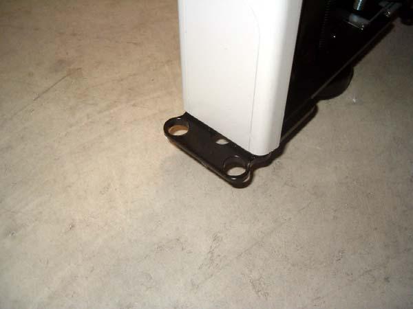
Angled Side Flush with Panel Face
|
|
|
- Ami Bryan
- 5 years ago
- Views:
Transcription


1 Identify and sort panels by like sizes, fabrics, surface type (tackable vs hard), and NON- POWERED vs POW- ERED. Non-powered panels ship without a powerway. Powered panels include a powerway. See below. Powered panels ship with powerway attached. Layout drawing will indicate powered panels with a V shaped line through the panel symbol. These panels should be placed accordingly to prevent moving powerways after the fact. The Universal Connector Bracket, or Porkchop is used to connect the bottoms of all MWall panels and the tops of all panels of equal height. This same bracket is used with 90, 45 and 120 degree connections. 1


2 Angled Side Flush with Panel Face It is important to plan for the connection of FUTURE panels while installing current panel. Start at a 2-way connection. Attach porkchop to the bottom of Panel A as shown for the 90 degree corner. Note that angled side is flush with panel face. On opposite end of Panel A, attach a Porkchop as shown for the next adjacent panel, in this case, a straight connection. Use tapered 1/4-20 screws included. Screws use a 3/16 hex drive. If cables will be running through to adjacent panels in the future, the perforated metal knockout on the raceway end must be removed. Firm push or strike a screwdriver into the middle of the knockout as shown. 2


3 Once the top of the knockout has broken away, rotate knockout out back and forth to remove. Panel B is to be installed 90 degrees to Panel A. On this panel, install a Pin in the outside corner of the raceway frame. Install a Pin in the outside corner of the raceway frame of Panel B on the side which will abut Panel A. 3


4 Attach Porkchop on opposite end of Panel B as shown Prior to installing Panel B, attach Porkchop to panel other end of Panel B for installation of future panel. Always think of the next adjacent panel and plan accordingly. Prior to installing Panel B, be sure all glides are minimized. Insert Pin on Panel B down into Porkchop on Panel A as shown. 4


5 Be sure Panel B is seated flush on top of Porkchop on Panel A. At TOP of Panels A and B, attach a Porkchop as shown. Porkchop should MIRROR porkchop on the bottom of Panel A. Use drill driver set on medium torque with a 3/ 16 hex drive to attach porkchops to the top of Panel A and B with 1/4-20 tapered screws supplied. 5


6 Panel A and B properly joined at a 90 degree equal height condition. Panel A and B properly joined at a 90 degree equal height condition. To install Panel C in a straight line, note the Porkchop extended from the bottom of Panel A. 6


7 Install 2 Pins at the bottom of Panel C on the end that is to abut Panel B. NOTE, BE SURE TO ATTACH A PORKCHOP to the other end of this Panel for the next panel in line. Insert Pins on Panel C down into Porkchop on Panel B as shown. Be sure Panel C is seated flush on top of Porkchop on Panel B. 7


8 At TOP of Panels B and C, attach a Porkchop as shown. Porkchop should MIRROR porkchop on the bottom of Panel B. Use drill driver set on medium torque with a 3/ 16 hex drive to attach porkchops to the top of Panel B and C with 1/4-20 tapered screws supplied. Panel D, low panel, will abut Panel A in a straight line. Configure the bottom of panels D and A as indicated in the straight connection shown for Panels B and C. See Previous. Attach Universal Straight HiLo bracket to the top of Panel D as shown. 8


9 Mark holes on Universal Straight HiLo (USH) on Panel A endcap and drill THROUGH Endcap, Through Steel Hanger Frame with 3/16 drill bit. NOTE, you may prefer to mark holes and move Panel D prior to drilling. Using screws supplied labeled For Straight HiLo Connections, screw though USH into Panel A (High Panel) as shown. Be careful not to over tighten and crush endcap. Shown is the bottom of Panel C, which was previously installed in a straight line abutting Panel B. At the opposite end of the straight connection, a Porkchop was installed for a panel to be installed at 90 degrees. 9


10 Pin Installed adjacent to Porkchop. Panel E is configured such that a Porkchop is attached for connecting Panel F in a 3-way connection. A Pin is installed adjacent to the Porkchop as shown for connection to Panel C. Insert Pin on Panel E down into Porkchop on Panel C as shown. Be sure Panel E is seated flush on top of Porkchop on Panel C. Note the Porkchop on Panel E is configured to connect Panel F. 10


11 At TOP of Panels C (on right) and E (on left), attach a Porkchop as shown. Porkchop should MIRROR porkchop on the bottom of Panel C. Panel F Panel E With Panel F configured with a Pin for a 90 degree connection, Insert Pin on Panel F down into Porkchop on Panel E as shown. Panel C Be sure Panel F is seated flush on top of Porkchop on Panel E. 11


 Panel G High (Left) Left hand panel (Panel G) is indicated when standing on the inside of")
12 At TOP of Panels E (in Middle) and F (on Left), attach a Porkchop as shown. Porkchop should MIRROR porkchop on the bottom of Panel E. Panel H (Right) Panel G (Left) Attach Panel G to other side of Panel E in a straight connection NOT shown here. Panel H is a low panel installed 90 degrees to Panel G. As shown, set up bottom of LEFT HAND PANEL with a Porkchop at 90 degrees. Panel H is set up with a Pin. Panel H Low (Right) Panel G High (Left) Left hand panel (Panel G) is indicated when standing on the inside of the 90 degree connection, opposite of the view shown here. LEFT HAND PANEL MUST ALWAYS GET THE PORKCHOP when connecting a 90 degree Hilo. 12
 and a larger bracket with one hole (LB1), bolted together with a 2 1/4 hex bolt and a nut.")


13 Panel G High (Left) Panel H Low (Right) Universal Corner HiLo bracket consists of 2 brackets. A small bracket with two holes (SB2) and a larger bracket with one hole (LB1), bolted together with a 2 1/4 hex bolt and a nut. Panel G High (Left) Panel H Low (Right) With nut barely threaded on bolt, insert teeth on SB2 into the right hand panel and engage down onto hanger frame slots about 3 inches from the top of the low panel. Insert drilldriver into bolt and hold SB2 down onto right panel. Tighten until bolt head is slightly below top of bracket. DO NOT OVER TIGHTEN. Holding SB2 down, engage teeth on LB1 into left hand frame going UP. Slowly tighten bolt so that panels draw together. All teeth must be engaged. NOTE, it is easier to engage LB1 if panels are temporarily set at less than 90 degrees. 13


14 Install end filler at every end of panel run with two taper bolts. The end of run filler is also used at the top of a straight HiLo connection. IMPORTANT - set drill on LOW TORQUE and gently tighten bolts to avoid breaking end fillers. Corner Fillers, or Tear Drops, are used to trim areas next to Porkchops at a 90 degree angle. 14


15 IMPORTANT - set drill on LOW TORQUE and gently tighten bolts to avoid breaking end fillers. Outlets are marked circuits 1-4. The layout drawing will indicate which outlet goes where per the design. NOTE - In some locations, ALL ELECTRICAL COMPO- NENTS must be installed by a licenced electrician. Install Duplex outlets by aligning the outlet interface with the powerway interface as shown. Slide outlet to the left on the left side, or to the right on the right side, until fully engaged on powerway as shown. Outlet cannot be installed upside-down. 15


16 Using screws provided for Outlets, screw outlet to powerway as shown. Only one screw, top or bottom, is required. NOTE - Outlets MUST be screwed to Powerways. Outlets are marked circuits 1-4. The layout drawing will indicate which outlet goes where per the design. Clip Ramp Up Arrow Safety Clip Install Jumpers as indicated WITH ARROWS on JUMPER modular end pointing UP as shown. Engage jumper fully onto powerway in one of the 2 end locations. Safety Clip MUST BE fully engaged over Clip Ramp to be fully installed. 16


17 Panel to panel jumpers connect two panels that are adjacent at a 90 or a straight connection. 18 inch is for straights only. 21 inch can be used on both. If jumping across a 3-way or 4-way, an extended jumper is needed. Pass Through cables are metal and engage powerway in the same manner as panel to panel. Engage jumper fully onto powerway in one of the 2 end locations. Safety Clip MUST BE fully engaged over Clip Ramp to be fully installed. Pass through cables pass through nonpowered panels. Specify the jumper that matches the length of panel to be passed through. IMPORTANT - PANELS CONNECTED ELECTRICALLY MUST BE CONNECTED ME- CHANICALLY. 17


18 Base in-feeds are installed at unused duplex outlet locations. ONLY ONE IN-FEED can be used on any connected run of powerways and jumpers. BREAK power between runs if more than one feed is needed. Pass end of base feed THROUGH Base Cover at desired outlet location. A licenced electrician must connect this end of the feed to building power. NOTE - In some locations, ALL ELECTRICAL COMPO- NENTS must be installed by an electrician. Install other end of feed as you would an outlet. 18


19 Screw feed to powerway as shown using screws provided labeled for Outlets. Slide base cover down length of feed until outlet bezel lines up with outlet hole. Rest bottom of base cover on spring clips such that clip barb protrudes up into relief hole at the bottom outside corners of the base cover. 19


20 Keeping bottom of base on spring clip, rotate top of cover up under lip of raceway frame as shown and snap flush with panel face. Base will need to be forced down under lip, depressing the spring clips below. Install duplex outlet covers in unused duplex outlet holes. To remove Duplex Outlet Covers, Base Cover must be fully removed. 20


21 Installed base cover with outlet and duplex outlet cover. To install topcaps adjacent to straight hilos, the perforated knockout must be removed at the end of the topcap which will abut the Hilo bracket. Using hand tool, GENTLY twist knockout free. Install topcap with the knocked out end abutting the hilo bracket. 21


22 Place topcap over topcap retainer and gently push down until topcap is seated properly on Porkchops. NOTE - topcap should be centered on panel such that screw tops are hidden from view. DO NOT bang topcaps down. Doing so could dent caps. If cap is too loose, spread topcap retainer wings slightly and reinstall. Properly installed panels should be LEVELED by adjusting glides at bottom of panels. Use Flatbar to raise panels slightly and turn glides by hand. Be sure to snug all floating glides down. Carpet grippers are supplied and may be used if desired. 22


23 Insert Right Hand Flipper Door Shelf End into a right hand hanger frame slightly above the level of a panel topcap. Anti-Dislodge Cam Insert shelf end into frame and down until firmly seated on hanger frame. Anti-dislodge Cam should rotate back as shelf end is inserted. Rotate Cam into hanger frame so this edge is vertical. Once end is firmly seated on frame, rotate cam into hanger frame so back edge of cam is parallel to panel face. To remove shelf end, rotate cam back out and lift end. Repeat this procedure for left ends and Mid Height Shelf Ends. 23


24 Hold shelf pan between shelf ends and lower over nuts on shelf end. This may require turning nuts out to loosen slightly. BE CAREFUL NOT TO SCRATCH paint on shelf ends as you insert and lower shelf. Shelf pan has two slot patterns on end. Use slot pattern as show to properly position shelf. Lock slot should be positioned at front on bottom shelf pan. 24


25 Tighten nut down to secure shelf. NOTE - Failure to tighten nuts can result in serious injury. Install top shelf pan in the same way, with the hole pattern for mounting a flipper door at the front as shown. NOTE - Top shelf and bottom shelf ARE THE SAME PART mounted in opposite directions. 25


26 NOTE - Lock slot faces towards panel on top shelf. Rest flipper door face assembly on top shelf with gear track hinges oriented as shown. Align holes on gear track hinges with holes on front of shelf pan and attach with screws provided labeled Flipper Doors. 26


27 Open and close door a few times. If required, door can be adjusted by loosening attachment screws and sliding left or right. Keys are attached to inside of door face. Remove key and test lock. Mid height shelves install in the same manner as flipper door units. 27


28 Tasklight brackets must be assembled to tasklights prior to installation. Insert hook on bracket into slot on light, align hole with hole on light. With screws provided, attach bracket to light. Be sure not to overtighten screws. Repeat procedure on other side of light. Hold light up under shelf pan. Bend light brackets to engage forward and rear edge flanges of shelf pan. Be sure each end of the brackets is firmly seated. Failure to do so could result in injury. 28


29 Teeth on bracket insert UP into hanger frame. Insert hook tooth at bottom of bracket into hanger frame at appropriate height and rotate bracket up into a vertical position. Mount top of bracket flush with top of topcap. Bracket will need to be lightly tapped to engage upwards fully and to prevent bracket from falling before installing top. Countertop brackets are handed. Each countertop requires at least two pairs of brackets. 29


30 Align countertop on center of panel. With screws provided labeled for Worksurfaces, attach bracket to worksurface. Use at least 2 screws per bracket. Secure 1 screw on each side of panel first to stabilize top, then complete attachment with remaining holes, alternating from one side of panel to the next. Shared cantilevers are used to support panel hung worksurfaces at a seam between two panels. Insert hook tooth up into hanger frame at the appropriate height. 30


31 Rotate cantilever down into hanger frame and engage down into slots 1/4 inch. Push down on cantlilever and make sure cantilever is fully engaged. NOTE - failure to engage cantilever properly can lead to injury. Cantilevers should be hung between 28 and 29 inches to achieve industry standard worksurface height and match structural pedestal heights. 31


32 Properly installed shared cantilever at 28 inches to top of cantilever. Side support rear brackets provide direct support for worksurfaces at the rear of corner worksurfaces or along worksurface sides. Insert hook tooth at top of bracket into hanger frame... Rotate bracket down into hanger frame and engage down 1/4 inch. Be sure bracket is fully engage on hanger frame. Failure to properly engage bracket could result in injury. 32


33 Structural pedestals provide support for worksurfaces. Screwing pedestals in requires removing top file drawer or top two box drawers. To remove pedestal drawers, pull drawers out completely. Note the black lever on drawer stop mechanism... On the right side of the pedestal, push lever down and hold... 33


34 On the left side of the pedestal, push lever up and hold. While levers are engaged, pull drawer out clear of ball bearing slides. Pedestals must be set at same height FROM TOP OF PANEL as cantilevers. Measure cantilever height from top of panel, then compare to pedestal height... Turn ped over on back and adjust glides accordingly to achieve the correct pedestal height. 34


35 Turn pedestal over and double check heights of all support elements to ensure that worksurfaces will be level. Corner centered on panel seams Rest worksurfaces on top of worksurface supports such that edges are 1/4 inch from panel face and that corners are aligned on the center of panel corners... 1/4 inch gap Seams between worksurfaces should be aligned with panel seams. 35


36 Align Worksurface seam with panel seam Worksurface should touch at seams and seams should be aligned with panel seams. Worksurfaces should touch While holding worksurfaces in place and maintaining alignment, screw worksurfaces to cantilevers with screws provided labeled For Worksurfaces. Use 2 screws for regula cantilevers and 4 screws for shared cantilevers. Install Flatplates at seams between worksurfaces in front of shared cantilevers. 36


37 Align pedestal flush with front of worksurface and screw to worksurface with screws labeled For worksurfaces. Use at least 2 screws at the front of pedestal. For best results, use screws at all 4 corners of pedestal. Push outer slide back and keep inner slide forward To replace drawers, push all ball bearing slides into pedestal BUT KEEP INNER BALL BEARING CARRIAGE pulled forward to front of slide. Carefully align track on drawer boxes with inner slide carriage and slowly insert drawer... Push drawer in to face, then open fully and close to ensure proper slide alignment. IT IS NOT NECESSARY to actuate levers on drawer stops while reinserting drawers. NOTE - BE SURE TO TEST LOCK ON PEDESTALS AND adjust as needed. 37


38 Install all grommet covers where needed. Install tackboards by aligning tackboard brackets with hanger frame slots approximate 1 inch above worksurfaces. Be sure tasklight cord is behind tackboard. Insert tackboard in and down. Be sure each side if firmly seated in hanger frame. 38


39 3 inch Tasklight cord managers can be used above tackboards to manage tasklight cords. Longer tasklight cord managers are available if no tackboard is being used. Tuck cord into manager and insert manager into hanger frame and push down. Workstation with completed components. 2-way base raceway shroud covers cables running in base raceway at 90 degree corners. Be sure gates are fully seated on raceway frame. Align cover with corner... 39


40 Wrap cover around gate legs and snap into place. Be sure cover is seated down on raceway frame and fully engaged over gate legs. 3-way base raceway shroud covers cables running in base raceway at 90 degree 3-way corners. Be sure gates are fully seated on raceway frame. Align cover with gap between panels... 40


41 Wrap cover around gate legs and snap into place. Be sure cover is seated down on raceway frame and fully engaged over gate legs. To install 2-way equal height post filler, raise gates on both panels up to access the inside TOP of the raceway frame... 41
 ON TOP of raceway frame")


42 Place 2-way bottom bracket (PF-12) ON TOP of raceway frame as shown... Using panel standard porkchop bolts, attached bracket to raceway frame. Re-seat gates on both panels down over base raceway frame. 42


43 At top of frame, remove topcaps and any tear drops previously installed. Align 2-way top bracket (PF-3) with outside teardrop holes at top of panels... Using standard porkchop bolts, attach top bracket to frames. NOTE - DO NOT OVER TIGHTEN. 43


44 Align 2-way Post Filler with corner. Rest 2-way post filler ON TOP OF receiving flanges on bottom bracket as shown... Rotate post filler up UNDER top bracket and align holes on post filler with holes on top bracket. 44


45 Using supplied #6 sheet metal screws, screw down through top backet into post filler. NOTE - DO NOT tighten screws fully. Leave approx 1/8 inch of screw out for next step... Insert post filler Topcap Retainer, (PF-15) UN- DER screw heads from previous step as shown. Align slots on topcap retainer with screws heads and square retainer to post filler face. 45


46 Tighten screws down onto topcap retainer to secure both retainer and post filler. Align Post Filler Topcap as shown... Slide topcap down over retainer. NOTE - Velcro dots ship with order to prevent topcaps from being dislodged on low panels where people might hit them or rest on them. 46


47 Completed installed Post Filler. NOTE - 2- way post filler sits slightly recessed in corner as shown. FOL- LOW SAME procedure for 3-way post fillers. However, 3-way fillers are designed to sit FLUSH with panel faces. To install INLINE powerpole on either a 3- way equal height or 2- way equal height post filler (shown), remove topcap and previously installed retainer if applicable. Loosen sheetmetal screws holding post filler approx 1/8 inch. STEP bracket should sit back approx 1/16 from top bracket edge Install step bracket (PF-1) on top of post filler top bracket such that screws hold Step down and approximately 1/16 inch back from top bracket edge as shown. Tighten screws to hold down Step and secure post filler. 47


48 Align inline pole with Step bracket... Slide pole up through hole cut in ceiling and then down ON TOP OF Step bracket such that bracket retains pole and prevents lateral movement. 1 3/4 x 1 3/4 hole will need to be cut in ceiling tile PLUMB with the top of the post filler. Pole will terminate above ceiling. A shroud is shipped with every pole which magneticall attaches to pole at ceiling height to trim hole. 48


49 Knockout perforated end of adjacent topcap and install such that topcap slides OVER extended portion of pole as shown. NOTE - Spreading the topcap retainer on the adjacent panel will ensure that the topcap firmly holds pole down. Be sure adjacent topcap is firmly seated to hold pole down. Install pole cover by sliding up into ceiling hole and snapping into place on pole. 49

50 Note - in some cases, pole cover is 2 pieces. Inline poles and post fillers are designed to be RETROFIT over electrical cables and data cables so minimize cable snaking. 50
Revised
 Indentify Non-powered panels and separate from Powered panels. Non-powered panel shown at left.. Powered panel shown at left has powerway mounted at factory. Also separate panels by surface type, width
OXYGEN INSTALLATION. Revision date
 12345 1 Hardware List 12345 Flat head wood screw #9 x 7/8 long with #2 Phillips drive, silver Used to attach surfaces and end panels Hex set screw ½-13 x 2 long with 1/4 hex drive, black Used on Legs Hex
compile system INSTALLATION GUIDE Updated January 2019
 INSTALLATION GUIDE Updated January 09 compile system Table of Contents Panels 0 Quick Connect Clips 0 Lock Clips 0 Panel Trims 0 Privacy Glass 0 Post Base Covers 04 Electrical 04 Power Distribution Harness
Interra Installation Manual
 Interra Installation Manual Instructions to install the Friant Interra panel system Friant & Associates, LLC Table of Contents Getting Started Introduction... 3 General Tools, Staging & Safety... 4 Before
Mirage Installation Manual
 Mirage Installation Manual General Information This installation manual provides necessary information for the safe installation of the Mirage product. WARNING: Failure to follow the instructions in this
Assembly Instructions
 InTandem Table System November 20 InTandem Table System - Worksurface #4 x/" 4 wood screw power beam Tools Provided T-0 Extended Torx Driver T-25 Torx Driver Additional Tools Required Soft protective
ZAPF PANEL SYSTEM ASSEMBLY INSTRUCTIONS. It is recommended that the components be installed in the sequence of this assembly manual.
 ZAPF PANEL SYSTEM It is recommended that the components be installed in the sequence of this assembly manual. ASSEMBLY INSTRUCTIONS OFFICE FURNITURE FOR THE INFORMATION AGE Table of Contents INSTALLATION
INSTALLATION: D1-NOTCH DRYWALL TRIM FLANGE
 T F W 604.549.979 604.549.9555 fluxwerx.com INSTALLATION: D1-NOTCH DRYWALL TRIM FLANGE fixture housing endcap kit optic kit join kit notch 2 cross section notch 4 cross section 4 4" 4-11/2" 4 /8 (111)
Installation Instructions
 by Plato Woodwork Installation Instructions Plato Woodwork, Inc. 200 Third Street SW P.O. Box 98 Plato, MN 55370 www.platowoodwork.com 800.328.5924 SECTION GUIDE GETTING STARTED PAGE # Installation Methods...
Topo Freestanding Applications - Private Office
 4 3 2 Topo Freestanding Applications - Private Office Combo Wrench If you have a problem, question, or request, call your local dealer, or Coalesse at 1.800.627.6770 Or visit our website: www.coalesse.com
Product must be installed as shown using the screws and brackets provided. Use of incorrect hardware could result in damage to the product.
 General Notes These installation instructions are intended to be comprehensive for a typical Keyeira/Presto configuration. Your configuration may differ. If you have questions contact Geiger Customer Service
LF Series Assembly Instructions
 LF Series Assembly Instructions 1998760 Revision A-10 Complete Series Master Packet 2010 Kimball International, Inc. T 800.482.1818 F 812.482.8300 Footprint Storage and Metal Filing Systems Assembly Instructions
Workbench Instructions for Assembly
 Workbench Instructions for Assembly Technical Electronic Workstations and Industrial Workbenches Includes: Cabinets Privacy Panels Stringers Bottom Shelves Table of Contents Tools Required for Assembly...
- 2 JOINER ALIGNERS - 2 JOINING BRACKETS - 4 HEX BOLTS. Factory pre-installed mud flange TOOLS REQUIRED: Phillips screwdriver, 5/16 nut driver.
 - 2 JOINER ALIGNERS - 2 JOINING BRACKETS - 4 HEX BOLTS TruGroove Drywall A3 MOUNTING Ceiling INSTALLATION System Overview These instructions review how to install drywall trim versions of TruGroove recessed
STAKS. Crossover Casegoods ASSEMBLY INSTRUCTIONS
 STAKS Crossover Casegoods ASSEMBLY INSTRUCTIONS Installation Sequence 1. Wall Panels a. Connector Kit Part Identification 3 b. T - 3 Panel Connection Preparation 4 c. X Panel Connection Preparation 5 d.
Compile Installation Manual
 Compile Installation Manual 07 OHSAS 800:007 ISO 900:05 ISO 400:05 Global Contract Inc. 565 Petrolia Road REVISED: FALL 07 North York, Ontario, MJ X8 Visit us on the Internet at globalcontract.com (46)
Footprint Mobile Assembly Instructions
 Footprint Mobile Assembly Instructions 1998754 Revision -1 Complete Series Master Packet If you have any questions concerning these instructions, please call Kimball Office Customer Service. 20 Kimball
HEAVY DUTY 11 STEEL CABINET
 HEAVY DUTY STEEL CABINET ASSEMBLY INSTRUCTIONS ONE DRAWER BASE CABINET 05-206 Parts List Part No Description Qty Image ONE DRAWER BASE CABINET Part No Description Qty Image SB- Cabinet Body EH-0 Euro Hinge
TrendWall Floor-To-Ceiling Panels Installation Instruction
 TrendWall Floor-To-Ceiling Panels Installation Instruction TrendWall Components Covered by this Instruction: Crown (and accessories) Floor Plate Solid Panel Filler Panel Wall Channel Door Section Pilaster
Linear Hook- on Worksurfaces
 Linear Hook- on Worksurfaces Linear Hook-On Worksurfaces come in three depths and seven lengths. Different worksurfaces have different reqirements for installation that are outlined below. 27 inch deep
Figure A. Figure B. Figure C. Figure D
 Xsite 1 Power/Data Tile and Components Tools Required Tape Measure Cordless Drill/Driver #2 Phillips Screw driver bit Rubber Mallet Flat Blade Screwdriver Figure A Hardware Required Provided as shown Installation
Assembly Instructions
 RoomScape Furniture System March 2013 - Bed Styles bed deck board bed deck board top cap top cap base glide middle side rail frame frame stacking device frame middle lower reinforcement side rail Single
Installation Instructions Standalone or continuous run configurations - 2 JOINER ALIGNERS - 2 JOINING BRACKETS - 4 HEX BOLTS
 - 2 JOINER ALIGNERS - 2 JOINING BRACKETS - 4 HEX BOLTS TruGroove Drywall A3 MOUNTING Ceiling INSTALLATION System Overview These instructions review how to install trimless drywall versions of TruGroove
Repair Instructions. Replacing a La Z Time Mechanism Side Subassembly. Remove the Back(s): Remove the Mechanism Assembly: CAUTION.
: Remove the Mechanism Assembly: CAUTION.") Replacing a La Z Time Mechanism Side Subassembly Tools Required: Slotted Screwdriver Power Driver 8" Driver Extension Ruler Note: Extension springs are not typically used on non-chaise standard width styles,
Replacing a La Z Time Mechanism Side Subassembly Tools Required: Slotted Screwdriver Power Driver 8" Driver Extension Ruler Note: Extension springs are not typically used on non-chaise standard width styles,
AIR MASTER SYSTEMS INSTALLATION GUIDE TABLE OF CONTENTS
 AIR MASTER SYSTEMS INSTALLATION GUIDE TABLE OF CONTENTS GENERAL INFORMATION...1 Freight Damage... 1 Repairing Paint Scratches...1 BASE CABINETS... 2 Drawer Removal and Reinstallation...2 Replacing Drawer
IMPULSE G2/PULSE STATIC BRIDGE & RETURN MODULE. Drill. Desk Connecting. Outside by fastening the supplied wood screws from the HK-67 kit through the
 PART # 1608990 STATIC BRIDGE & RETURN MODULE 1. This sheet covers the steps to install a static bridge or return module with the FX no hinged access panel back option to a height adjustable freestanding
EmagiKit. Privacy Pod Plus. Quiet. Easy. Affordable. INSTRUCTIONS ASSEMBLY
 EmagiKit Privacy Pod Plus Quiet. Easy. Affordable. INSTRUCTIONS ASSEMBLY DIMENSIONS AND COMPONENTS 47 47 Ceiling Unit 2-B 2-L 2-R Glass Door Corner Trim Door Handle 90 Adjustable Height Work Surface 1-B
CM340B STOP READ ALL OF THE FOLLOWING INSTRUCTIONS BEFORE REMOVING SERVER CABINET FROM SKID
 CM340B STOP READ ALL OF THE FOLLOWING INSTRUCTIONS BEFORE REMOVING SERVER CABINET FROM SKID NET-ACCESS Server Cabinets Panduit Corp. 2010 INSTRUCTIONS CM340B CS1 (1) Base Cabinet (2) Solid Side Panels
FlexFrame - Storage Components and Skins
 FlexFrame - Storage Components and Skins 1/4 Square Drive Ball-Point Hex-Bit Socket 1/8 Short Hex, 1-1/2 Overall Length McMaster Part # 54075A44 Table of Contents Topic Page Storage Components 2 General
Assembly Instructions
 Unite Panel System Hinge Door July 2016 #12 x / slotted hex washer head bolt Figure 1 threshold bracket frame Detail F threshold bracket threshold bracket (installed) #12 x / slotted hex washer head bolt
Bathroom Installation Guide
 Bathroom Installation Guide Please read instructions carefully and check products before starting. Products should be fitted/installed by an experienced and competent fitter, failure to do so may invalidate
P.O. Box 8400 Green Bay, WI (920)
") P.O. Box 8400 Green Bay, WI 54308-8400 (920) 468-2165 Change Notice No. 112 Implemented By: KI-Pembroke Notification By: Scott Vissers Date: 03/15/10 Component Product Title: Series XXI Lateral Filing
P.O. Box 8400 Green Bay, WI 54308-8400 (920) 468-2165 Change Notice No. 112 Implemented By: KI-Pembroke Notification By: Scott Vissers Date: 03/15/10 Component Product Title: Series XXI Lateral Filing
IMPULSE G2/PULSE STATIC BRIDGE & RETURN MODULE. Drill. Desk Connecting. Outside by fastening the supplied wood screws from the HK-67 kit through the
 PART # 1608990 STATIC BRIDGE & RETURN MODULE 1. This sheet covers the steps to install a static bridge or return module with the FX no hinged access panel back option to a height adjustable freestanding
Modular Drawer & Door Systems Installation Instructions Locking Drawers and Receding Doors
 Modular Drawer & Door Systems Installation Instructions ocking Drawers and Receding Doors Pre-Installation Before you begin installation: 1. Read through the installation procedure before starting the
Arlink 8000 Workstation
 Arlink 8000 Workstation Instructions for Assembly Introduction Basic Frame Assembly Worksurface Assembly Drawer and Power Beam Assembly Light Fixture and Shelves Worksurface Grounding Instructions Wrist
Dura-Lock Roof System
 DLR-14 Dura-Lock Roof System Assembly and Installation Instructions Read the instructions before starting the job. They explain the steps required to produce a finished product that will meet factory specifications.
Installation And Care Instructions. Vertical Honeycomb Shades
 Installation And Care Instructions Vertical Honeycomb Shades Rev 5/2013 Table Of Contents Getting Started... 3 Parts Overview... 4 Materials Required... 5 Tools Required... 6 Outside Mount Installation...
Laminate Cabinet Installation Instructions
 Laminate Cabinet Installation Instructions www.easygaragestorage.com/installation How To Use These Instructions Thank you for your purchase! Please read each step of this manual thoroughly to ensure proper
A524 ASSEMBLY & INSTALLATION INSTRUCTIONS BELLADONNA PENDANT CASTLETON, VERMONT USA SYNCHRONICITYLIGHTING.COM Rev A 1 OF 7
 1 OF 7 COMPONENT PARTS A B Canopy Mounting Bracket C Anchor (4) D #10 Wood Screw (4) E F G H Safety Cable Ground Screw Cupped Washer Safety Cable screw I Gripper (2) J Barrel Knob (4) K L Lightbar Fixture
ROS-APT Caucus Plinth Table with Trough Note: Details apply, however the actual configuration of your table may vary from what is depicted here.
 ROS-APT Caucus Plinth Table with Trough Note: Details apply, however the actual configuration of your table may vary from what is depicted here. Parts List - Tables Tops, Top Insert Panels and Base panels
Office Partitions WARNING. Assembly Instructions. Customer Service A S S E M B LY HARDWARE H1 H2 H3 H4 H5 H8 H9 H10 H11 H12
 Customer Service 1-800-645-2986 Assembly Instructions WARNING In order to prevent structural failure, instability, t i p - o v e r, and/or serious injury, please follow i n s t ructions care f u l l y.
INSTALLATION AND CUSTOMER CARE INFORMATION FOR SC FREESTANDING STERILIZATION CENTERS
 INSTALLATION AND CUSTOMER CARE INFORMATION FOR SC144-200 FREESTANDING STERILIZATION CENTERS General Information: Many Artizan Design Free-standing Sterilization Centers are custom designed and built to
MobileTrak5 Installation Instructions
 MobileTrak5 Installation Instructions PLEASE OPEN ALL BOXES & CHECK TO MAKE SURE YOU HAVE ALL PIECES REQUIRED READ ALL INSTRUCTIONS BEFORE STARTING Tools Required for Assembly 7/16, 1/2 Wrench Phillips
Preference Collection and Treatment Console INSTALLATION GUIDE
 Preference Collection 5580.69 and 5580.96 Treatment Console INSTALLATION GUIDE WARNING Failure to install the 5580 as described in this installation guide may cause the unit to collapse, resulting in serious
Copyright Black Box Corporation. All rights reserved Park Drive Lawrence, PA Fax
 Copyright 2003. Black Box Corporation. All rights reserved. 1000 Park Drive Lawrence, PA 15055-1018 724-746-5500 Fax 724-746-0746 JULY 2003 RM3010A RM315-R2 RM323-R2 RM329 RM451 RM457 RM3020A RM316 RM324-R2
 For Wallbed models: KING SIZE INSTRUCTION BOOKLET #C1 Watch step by step installation instructions at: https://www.wallbedsbywilding.com/wallbed-installation-studio-series/ WARNING! ALL MURPHY/WALLBED
Privacy Wall Glass Selections - Polished Edge Slider Door
 Privacy Wall Glass Selections - Polished Edge Slider Door 3/6" HEX BIT PUTTY KNIFE #2 ACR BIT SUCTION CUP HOLDERS DOOR LEAF: Satin Tempered Clear Tempered LOCTITE 425 SIDE LIGHT ETCHED GLASS STYLES: Satin
Before Assembling the Storage Wall
 Chapter 1 Assembling the Lista Storage Wall Lista provides two types of standard Storage Walls: B251 and B255. The design, construction, assembly, and quality are identical for both types, however, B251
Bridges II Installation Guide. Effective June 2017 DESIGN GUIDE
 Bridges II Installation Guide Effective June 07 DESIGN GUIDE Structure and Worksurfaces Beam Applications Supporting Structure Legs and Beams Telescopic Beam 0 Leg Storage Table Beam Sliding Return Round
Series 1500 Aluminum Door Canopy
 Series 500 Aluminum Door Canopy with Sidewings It is our recommendation that you read instructions carefully prior to assembly and installation. Series 500 with Sidewings mounting bar (A) top trim (B)
MantelMount. TM1A Installation Instructions IMPORTANT SAFETY INSTRUCTIONS - SAVE THESE INSTRUCTIONS
 MantelMount TMA Installation Instructions IMPORTANT SAFETY INSTRUCTIONS - SAVE THESE INSTRUCTIONS TM Thank you for choosing the MantelMount television wall mount. Please read this entire manual before
INSTALLATION GUIDE FOR METAL LABORATORY CASEWORK
 LABORATORY Casework & Cabinets INSTALLATION GUIDE FOR METAL LABORATORY CASEWORK RDM Industrial Products, Inc. RDM LAB CABINET INSTALLATION GUIDE TABLE OF CONTENTS GENERAL INFORMATION...1 Freight Damage...1
LAN Locker Adjustable Shelves
 Adjustable Shelves LAN LOCKER ADJUSTABLE SHELVES * Adjustable Shelves are available for LAN LOCKER widths: 24, 30, 48, 60, and 72. * When installing more than one Adjustable Shelf, it is recommended that
INSTALLING YOUR NEW SPRING LIFT ARM KIT
 INSTALLING YOUR NEW SPRING LIFT ARM KIT 1. Measure the distance that the roof is to be raised. [If your lift system is completely non-functional, you will need to calculate or estimate this distance as
INSTALLATION INSTRUCTIONS
 INSTALLATION INSTRUCTIONS SOLID PHENOLIC TOILET PARTITIONS 1080 DuraLineSeries Class-A Fire Rated Includes Institutional Hardware Option.67 IMPORTANT: Storage and Handling Information on last page. Review
Low Headroom Rear Mount TorqueMaster
 Low Headroom Rear Mount Supplemental Instruction Insert This supplemental installation instruction is to be used as a supplement to the main Installation Instruction and Owner s Manual provided with the
https://www.wallbedsbywilding.com/wallbed-installation-studio-series/
 For Wallbed models: KING SIZE INSTRUCTION BOOKLET #C1 Watch step by step installation instructions at: https://www.wallbedsbywilding.com/wallbed-installation-studio-series/ WARNING! ALL MURPHY/WALLBED
Hover. Installation Instructions. Raised Panel. Version
 Installation Instructions Version 8-2-17 Raised Panel Table of Contents Page Raised Panel Trough 3-13 Platform Trough 14-20 Platform 120 Degree Trough 21-24 Electrical 25-28 Type A Electric Bases 29-31
Sentinel Series Cigar Humidor End Tables
 Sentinel Series Cigar Humidor End Tables Assembly Instructions Models: Sentinel 500, 1000 and 1500 Style: Contemporary SENTINEL ASSEMBLY INSTRUCTIONS Congratulations! You have purchased a superior cigar
Height Adjustable Benching End Panel and Utility Pole
 Height Adjustable Benching End Panel and Utility Pole Tools required: END PANEL Jig Saw Power Drill END PANEL WITH UTILITY POLE Bit Holder Long #2 Square Drive Bit 5mm Hex Drive Bit UTILITY POLE Level
NOVO INSTALLATION MANUAL
 NOVO INSTLLTION MNUL friant.com/novo 2 NOVO INSTLLTION MNUL General Information... 4 Safety & Support... 5 Installation Tools... 6 Staging & Installation... 7 Panels & Connectors... 8 Electrical... 18
Side Mount INSTRUCTION BOOKLET #C122 BED STYLE: PARK CITY
 Side Mount BED STYLE: PARK CITY INSTRUCTION BOOKLET #C1 WARNING! ALL MURPHY/WALLBED SYSTEMS CONTAIN STORED ENERGY. FAILURE TO USE AND FOLLOW THESE INSTRUCTIONS DURING THE INSTALLATION PROCESS COULD RESULT
INSTALLATION AND CARE INSTRUCTIONS
 INSTALLATION AND CARE INSTRUCTIONS Vertical Applications Honeycomb Shades 52 C8-10-3401 Rev 2/14 CONTENTS Introduction...2 Before You Begin...3 Vertical Application Parts Overview...4 Materials Required...5
INSTALLATION TORSION SPRING FRONT OR REAR MOUNT LOW HEADROOM. 1 Cutting Vertical Track. 2 Fully Adjustable Jamb Brackets
 TORSION SPRING FRONT OR REAR MOUNT LOW HEADROOM Wayne Dalton, a division of Overhead Door Corporation P.O. Box 67, Mt. Hope, OH., 44660 Supplemental insert Copyright 2015 Wayne Dalton, a division of Part
======================================================================================== ( DR / DR) JK WRANGLER MOD RACK
 JK WRANGLER MOD RACK") (10984 4DR / 10982 2DR) JK WRANGLER MOD RACK INSTALLATION SHEET Important Notes: Some brands of windshield light brackets and snorkels may not be compatible with the 10984 MOD Rack System. Body lifts are
(10984 4DR / 10982 2DR) JK WRANGLER MOD RACK INSTALLATION SHEET Important Notes: Some brands of windshield light brackets and snorkels may not be compatible with the 10984 MOD Rack System. Body lifts are
KIT. Assembly Instructions. HayDay, LLC
 KIT Assembly Instructions HayDay, LLC 1-800-732-1654 www.stablegrazer.com Read completely through the assembly instructions before starting assembly. The Stable Grazer Kit comes in two boxes. Remove all
 INSTRUCTION BOOKLET #C0 Watch step by step installation instructions at: https://www.wallbedsbywilding.com/wallbed-installation-studio-series/ WARNING! ALL MURPHY/WALLBED SYSTEMS CONTAIN STORED ENERGY.
Sentinel Series Cigar Humidor End Tables
 Sentinel Series Cigar Humidor End Tables Assembly Instructions Models: Sentinel 500, 1000 and 1500 Style: Traditional SENTINEL ASSEMBLY INSTRUCTIONS Congratulations! You have purchased a superior cigar
INSTALL INSTRUCTIONS WELCOME TO THE NEWAGE PERFORMANCE CABINETRY SERIES NEWAGE STEEL WELDED CABINETRY
 NEWAGE STEEL WELDED CABINETRY WELCOME TO THE NEWAGE PERFORMANCE CABINETRY SERIES ALL CABINETS MUST BE MOUNTED TO STUDS ON A SECURE WALL, AS PER THESE INSTRUCTIONS. FAILURE TO DO SO MAY RESULT IN SERIOUS
Exponents Bench Cushion
 Exponents Bench Cushion Power Drill #2 Phillips Bit Bit Holder Page 1 of 2 939500640 Rev A 1. Place cushion on top of the bench, so the black Coalesse tag is in the right rear corner of the bench. 2. From
CONTENTS TOOL LIST U P S I D E I N N O V A T I O N S, L L C RAMP AND STEP SYSTEM ASSEMBLY INSTRUCTIONS. Revised: June 2013
 U P S I D E I N N O V A T I O N S, L L C RAMP AND STEP SYSTEM ASSEMBLY INSTRUCTIONS TOOL LIST Required Tools: - Reciprocating Saw with Metal Cutting Blade - Drill - 7/16 Drill Bit for Metal Drilling -
LIGHT FIXTURES MUST BE COMPLETELY INSTALLED PRIOR TO CEILING CONSTRUCTION
 CAUTION: BEFORE BEGINNING INSTALLATION REVIEW LAYOUT DRAWINGS, AND SHIPMENT. MAKE SURE ALL LIGHT S AND MATERIALS ARE ON SITE AND READILY ACCESSIBLE. IF ANY ICON MATERIALS ARE MISSING, CONTACT ICON INTERNATIONAL
WEIGHT ADJUSTABLE ESPREE. Model 2ESP-WA-C48- Model 2ESP-WA-C60- 2ESP-WA Rev B 8/17 ASSEMBLY AND OPERATION
 WEIGHT ADJUSTABLE ESPREE PNEUMATIC TABLE BASE 2ESP-WA Rev B 8/17 Model 2ESP-WA-C48- Model 2ESP-WA-C60- = SLV, BLK or WHT ASSEMBLY AND OPERATION PARTS AND TOOLS PLEASE REVIEW these instructions before beginning
TorqueMaster Replacement Spring
 TorqueMaster Replacement Spring Installation Instructions NOTE: Use these installation instructions in conjunction with the TorqueMaster Repair / Replacement Spring Program literature. Copyright 999 Wayne-Dalton
Preference Collection 5580 Treatment Console INSTALLATION GUIDE
 Preference Collection 5580 Treatment Console INSTALLATION GUIDE 0 WARNING Failure to install the 5580 as described in this installation guide may cause the unit to collapse, resulting in serious injury
Installation Manual for Metal Emperor Lockers
 P a g e 1 Table of Contents Page General Notes and Tools Required 2-3 Assemble Shelves with Coat Hooks/Coat Rods 4 Fastening Chart 5 Knock Down Locker Assembly (Banks of Three) 6-12 Appendix A: Dress End
WPS crew Doors Installation instructions
 WPS-132-133 crew Doors Installation instructions ORDER OF INSTALLATION FOR A COMPLETE ENCLOSURE OF A CREW WPS (Weather Protection System) IS AS FOLLOWS: 1. Heater 2. Rear Thresholds - Right Hand & Left
Diva Acoustical Ceiling
 Installation Instructions Diva Acoustical Ceiling CONTENTS Important User Information...........................2 Safety Precautions.................................3 Required Tools....................................3
Replacing the Reciprocator on the SWF Compact Series Machine (601C and 1201C)
") Follow the instructions below to replace the reciprocator in the SWF Compact series machines. The tools required can be found in the tool kit that came with the machine. Preparation 1. First, place the
Follow the instructions below to replace the reciprocator in the SWF Compact series machines. The tools required can be found in the tool kit that came with the machine. Preparation 1. First, place the
bridges Installation Manual
 bridges Installation Manual 0 OHSAS 800:007 CGSB #0HS-009 ISO 900:008 CGSB #96- ISO 00:00 CGSB #EMS-00 Global Contract Inc. 6 Petrolia Road North York, Ontario, MJ X8 Visit us on the Internet at globalcontract.com
Geiger Rhythm. Right ON SITE. Installation Principles
 ROS-GRW Geiger Rhythm Wall 1BGRZ3 Tools Required o Installation drawing of product layout o Cordless drill o #1, #2 & #3 Philips and Robertson Drill bits o Level o Measuring Tape Page 1 ROS-GRW Geiger
Door window. Front door window, assembly overview
 64-50 Door window Front door window, assembly overview 1 - Window channel Pushed onto flange 2 - Door window Removing Page 64-52 Adjusting Page 64-53 3 - Door 4 - Outer window channel Pushed onto flange
CM543 STOP READ ALL OF THE FOLLOWING INSTRUCTIONS BEFORE REMOVING CABINET FROM SKID
 CM543 STOP READ ALL OF THE FOLLOWING INSTRUCTIONS BEFORE REMOVING CABINET FROM SKID NET-SERV Co-Location Cabinet (S752S2C122B) Panduit Corp. 2011 INSTRUCTIONS CM543 FRONT OF CABINET REAR OF CABINET NOTE:
Interactive Monitor Arm
 Interactive Monitor Arm Tools Required -5mm Allen wrench -Phillips screwdriver -Plastic mallet There are two ways to attach a Monitor Arm to a Full Frame; with a Beam, or with a Post Mount. Both methods
Footer & Base Plate Assembly. installation guide. ILINE power/data beam
 Phase Footer & Base Plate Assembly installation guide ILINE power/data beam Phase Materials and Tools. ILINE Postsleeve Components Top Cap Data Face Plate Post Sleeve Post Sleeves shipped with orders after
 INSTRUCTION BOOKLET #C10 Watch step by step installation instructions at: https://www.wallbedsbywilding.com/wallbed-installation-studio-series/ WARNING! ALL MURPHY/WALLBED SYSTEMS CONTAIN STORED ENERGY.
Installation Manual for Metal Toilet Partitions Standard Series
 For Video instructions http://www.hadrian-inc.com/tech-data/installation/toilet-partitions.aspx P a g e 1 Table of Contents Page General Notes and Tools Required 3 STEP 1: Establish Floor Bracket Locations
INSTALLATION AND CARE INSTRUCTIONS
 INSTALLATION AND CARE INSTRUCTIONS Skylight Manually Operated Honeycomb Shades 20 C8-10-1806 2/15 1 INTRODUCTION Thank you for purchasing our product. Your new shade has been custom built for you from
a.k.a. casegoods instructions
 a.k.a. casegoods instructions a a.k.a. workwall installation IMPORTANT NOTES Failure to install product according to installation instruction will result in loss of warranty. Tools required for assembly
PROFILE Flat Panel Console System Installation Manual
 PROFILE Flat Panel Console System Installation Manual Table of Contents Page Introduction... 2 Important Safety Information...3, 4 Installation Overview... 4, 5, 6 Single Sided/Single Unit... 7 Double
Installation Instructions
 Installation Instructions 000964 Revision F Installation Instructions for PIRIT Read this manual fully prior to starting installation. Call American eating Customer ervice with any questions. What you
Installation Instructions
 Installation Instructions Self-Cleaning Radiant Trivection Electric Slide-In Range JS998 Questions? Call 800.GE.CARES (800.432.2737) or Visit our Website at: www.geappliances.com BEFORE YOU BEGIN Read
Installation Instructions
 Installation Instructions Self-Cleaning Radiant Electric Slide-In Range JSP42, JS968, JS900, JS905, JSP46 If you have questions, call 1.800.GE.CARES or visit our website at: ge.com Before You Begin Read
REPAIR INSTRUCTIONS. Cat. No Cat. No MILWAUKEE ELECTRIC TOOL CORPORATION. SDS Max Demolition Hammer. SDS Max Rotary Hammer
 Cat. No. 9-0 SDS Max Demolition Hammer Cat. No. -0 SDS Max Rotary Hammer MILWAUKEE ELECTRIC TOOL CORPORATION W. LISBON ROAD BROOKFIELD, WISCONSIN 00-0 8-9-0 d 000 8-9-0 d Special Tools Require Forcing
7878 K940. Checkpoint Antenna. Kit Instructions. Issue B
 7878 K940 Checkpoint Antenna Kit Instructions Issue B Revision Record Issue Date Remarks A July 7, 2009 First issue B Nov2013 Revised the Checkpoint installation procedures for 7878 and 7874 scanners Added
WILDING WALLBEDS INSTALLATION INSTRUCTION Side Mount
 WILDING WALLBEDS INSTALLATION INSTRUCTION Side Mount For Wallbed models: Do-It-Yourself Insturction booklet C92 WARNING! ALL MURPHY/WALLBED SYSTEMS CONTAIN STORED ENERGY. FAILURE TO USE AND FOLLOW THESE
INSTALLATION AND CUSTOMER CARE INFORMATION FOR SC FREESTANDING STERILIZATION CENTERS
 INSTALLATION AND CUSTOMER CARE INFORMATION FOR SC120-200 FREESTANDING STERILIZATION CENTERS General Information: Many Artizan Design Free-standing Sterilization Centers are custom designed and built to
Please read and understand all instructions before beginning. These instructions cover impact and non-impact aluminum French Door 650/750.
 The performance and proper operation of a door is only as good as the installation. By following these instructions, the probability of a good installation greatly increases. Please read and understand
U.S. Rack, Inc Falcon Drive, Madera, CA APR17 INSTALLATION AND USE INSTRUCTIONS for SIDE-MOUNT LADDER RACK
 U.S. Rack, Inc. 2850 Falcon Drive, Madera, CA 93637 15APR17 INSTALLATION AND USE INSTRUCTIONS for SIDE-MOUNT LADDER RACK WARNING: Do NOT attempt to install or use this rack without following all instructions.
Dublin Stalls Installation Instructions
 Dublin Stalls Installation Instructions RAMM Horse Fencing and Stalls 13150 Airport Hwy. Swanton, OH 43558-9615 1-800-434-8456 Rev. 9/13/17 Part Identification Round Track Bracket (4) (Not Painted) Round