MANET CONSTRUCT. The MANET CONSTRUCT System MANET CONSTRUCT
|
|
|
- Evelyn Nicholson
- 5 years ago
- Views:
Transcription


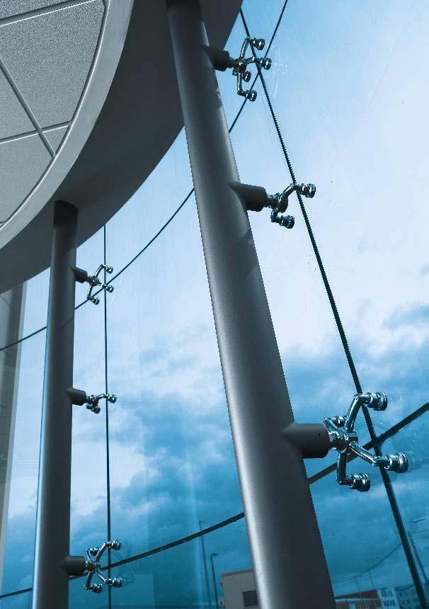
1 The MANET CONSTRUCT System MANET CONSTRUCT External and internal walls, façades and roofs of glass require construction systems that satisfy the highest demands in terms of functionality and design. Providing sophisticated technology and ensuring a harmonious design, the MANET CONSTRUCT range of hardware meets the specific requirements of all-glass systems, setting truly new standards in the process. The broad product portfolio flush-mounted single-point fixings, clamp fittings and the other construction hardware components ensures optimum planning reliability with respect to both the structural engineering requirements and visual appearance of the ensuing glass construction. All components of the MANET CONSTRUCT system from the point fixings to the spider are designed to ensure extensively constraint-free installation and effective load transmission to the substructure. In formal terms, the MANET CONSTRUCT system is assigned to the MANET product group, providing structural and safetyrelevant solutions that extend and complement that portfolio. Z Certificate of General Building Approval for MANET CONSTRUCT Spiders Report No MANET CONSTRUCT Point fixings EA50/ESA50 Dated Z Mark of conformity awarded to MANET CONSTRUCT products Spider Connection system EV single-point fixings 52
2 53

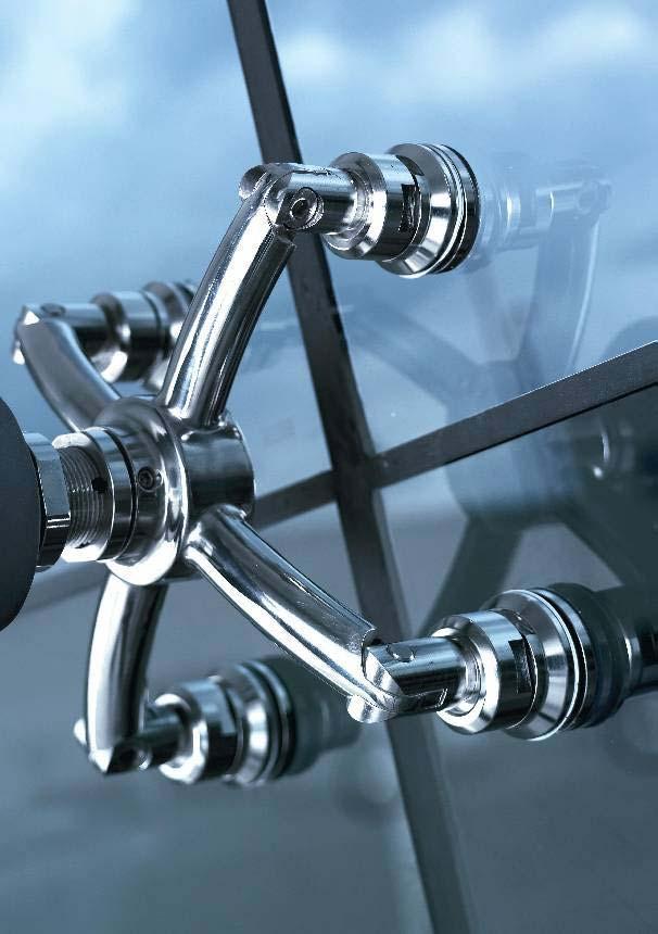
3 Spider System The MANET CONSTRUCT spider Offering fascinating design features for any façade, whether straight, segmented or rounded with curved glazing, the MANET CONSTRUCT spider adds aesthetic allure to connection efficiency. The arms of the spider absorb the load at all points of contact. Carrying a German certificate of general building approval, the spider system serves as the connection element to a central point on the substructure. The spider is designed for fitting the associated MANET CONSTRUCT single-point fixings EA (clamp fitting) and ESA (countersunk fitting). The MANET CONSTRUCT spider can be used as a onearm, two-arm (90 and 180 ), three-arm or four-arm element, covering all the requirements of each individual construction project. The spider is secured to the substructure by means of a standardised universal adapter. In the event of asymmetrical loading, anti-rotation locks incorporated within the spider hub and the substructure connector prevent the possibility of system twist. Possible spider applications for a façade Clamp fitting EA 50 Universal adapter Countersunk fitting ESA 50 MANET CONSTRUCT spider Eyelet Fork connector 54
4 spider connection possibilities 1. Connection via bracket Spider construction with universal adapter connected to a screw-fixed standard bracket for mounting onto the substructure profile Connection via strut Spider construction featuring universal adapter screwed into a strut attached to the rear-trussed primary construction Connection directly to substructure profile Spider construction with universal adapter, screwed into a socket connector welded onto the substructure profile

5 Single-point Fixings for Spiders MANET CONSTRUCT single-point fixings for spiders The standard single-point fixings designed for the MANET CONSTRUCT spider are the EA/ESA 50 fittings. Clamp fittings for overhead glazing systems and countersunk fittings preferred for vertical glazing systems are included in the standard range and available for relevant glass thicknesses of 10/12/17.5 and 21.5 mm. Stresses in the glass arising from deformation/expansion are reduced by an interfacial elastomer pad located in the front part of the mounting Gutachten zu Verwendbarkeitsnachweisen Universität (TH) Karlsruhe Drilling the glass Countersunk bore for countersunk fittings Stress loading theory ø ø thickness =5 Through-bore for clamp fittings ø thickness f max Pressure/ Suction The requisite glass thickness is determined by static analysis. Pre-dimensioning service available on request. 56
6 Spiders and Accessories Spider designs and accessories The spiders are of modular design with one to four arms. They are secured to the substructure by means of the type-tested M 36 x 2 universal adapter. The hub diameter is 70 mm and the spider has an overall height of 117 mm including the sockets for the single-point fixings (rear face of glass) Order data Stainless steel ø 70 Spider, one-arm Art.-No ø 70 Spider, two-arm, 90 Art.-No ø 70 Spider, two-arm, 180 Art.-No ø 70 Spider, three-arm Art.-No ø 70 Spider, four-arm Art.-No
7 Spiders and Accessories 40 Order data Wall fixing for spiders Art.-No M36x2-LH Connection by others Spider hub connection M36x2-RH 8 55 Ø140 Ø100 M36x2-LH Ø ±5 47 Fixing screws M12-M16, by others 120 Universal adapter Stainless steel Art.-No Ø14 Connection bracket Stainless steel for mounting onto the substructure Art.-No Grub screw (anti-rotation lock) Check bore MANET CONSTRUCT Clamp fitting Stainless steel EA 50 with 3D joint and fork connector (see page 59) MANET CONSTRUCT Countersunk fitting Stainless steel ESA 50 with 3D joint and fork connector (see page 59) 58
8 Series EA 50 Series ESA 50 Clamp fitting of the series EA 50 for MANET CONSTRUCT spiders. Available in a disk size of 50 mm. Countersunk fitting of the series ESA 50 for MANET CONSTRUCT spiders. Available in a counter-bearing disk size of 50 mm. Dimensions in mm Dimensions in mm Ø50 20 axial±2.5 Ø50 Ø32 20 axial±2.5 10/ Type EA 50 Order data for complete series EA 50 fittings thickness mm 10/ Article No. Stainless steel Type ESA 50 Order data for complete series ESA 50 fittings thickness mm Article No. Stainless steel Load-bearing capacities of single-point fixings for spiders Fitting type EA 50 ESA 50 Normal force N F kn kn Transverse force Q F 7.24 kn 6.64 kn Characteristic loadability values of the mountings exposed to normal and transverse forces. The dimensioning values are derived from these data by dividing with a safety coefficient m =
9 Spiders Geometric data for glass drilling operations 117 thickness ±5 241 M36x2-LH 73 MANET CONSTRUCT spider installation Important advisory! MANET CONSTRUCT single-point fixings and MANET CONSTRUCT spider assemblies may only be used in accordance with the regulations of the associated certificate of suit- ability, certificate of general building approval and type test report or equivalent national regulations. The original assembly and installation instructions in each case are binding. 1. Fitting the MANET CONSTRUCT universal adapter and spider to the substructure Spider Universal adapter Connection bracket Right-hand thread Left-hand thread Once the fine adjustment of the substructure has been completed, the spider can be installed. Note: Ensure compliance with the MANET CONSTRUCT universal adapter datasheet! Wind the MANET CONSTRUCT universal adapter into the threaded hub socket of the spider two to three turns. Screw the spider and universal adapter into the female thread of the connection bracket mounted on the substructure using a wrench applied to the flats, until the thread becomes visible in the check bore. Axial adjustment range ± 5 mm (thread must remain visible in the check bore!). Wind in the grub screws with spigot extension in order to secure the assembly against rotation/twist. Tighten the lock nuts of the universal adapter. 60
10 2. Fixing MANET CONSTRUCT fittings to the glass Countersunk fitting Clamp fitting Ø50 Ø32 20 Ø / axial±2.5 axial± Clamping / countersunk disk EA50 M A =12Nm panel (symbolic representation of bore) EPDMpad EPDMpad Counter-bearing disk assembly Fit the clamping / countersunk disk of the fitting through the hole in the glass panel and screw into the counter-bearing disk assembly using the MANET wrench (tightening torque 15 Nm). ESA50 M A =12Nm POM-ring POM-ring 3. Installation of the glass panels with fittings onto the MANET CONSTRUCT spider Cap nut panel with preassembled fittings Fork connector 1. Fix the fork connector with the cap nut to the spider arm using a hexagonal socket head cap screw (M10 x 16-70). Do not tighten! 2. Raise the pre-assembled glass panel to the point of installation. 3. Connect the mounting with the fork connector using the cap nut. 4. Adjust for tolerances using the DORMA universal adapter (± 5 mm). 5. Tighten the cap nut (50 Nm) using the MANET open-jaw wrench. 6. Tighten the hexagonal socket head cap screw M10 x to 15 Nm. Caution! Make sure that the threads of the cap nut are not crossed! Caution! Tighten the cap nut first before removing the glass panel lifting/support appliance (tightening to be performed in unloaded condition). Installation tools Additionally required standard tools: 46 mm A/F M 8 Torque wrench with socket, 19 mm A/F 19 mm A/F For MANET CONSTRUCT singlepoint fixings: EA 50 / ESA 50 61
11 Spiders Approvals and certificates The MANET CONSTRUCT spider assembly with universal adapter is generally approved according to German regulations for construction applications. Its suitability can also be verified by static analysis on the basis of the type test carried out, using a standardised dimensioning process for each individual application. All certificates, approvals and type test reports are available from DORMA-Glas. 2-26/03 Darmstadt Regional Administrative Authority, Test Report No. 2 26/03 Z German Institute for Building Technology, Certificate of General Building Approval Darmstadt Regional Administrative Authority, Test Report No. 3 26/03 Z /03 Mark of conformity awarded to MANET CONSTRUCT products Static values and load-bearing capacities Static analyses for individual applications are performed on the basis of the type test. The dimensioning diagram used in the respective type tests can also be applied for pre-dimensioning in the initial planning stage. All the external stress loads acting on the spider assembly must be determined in advance in order to enable the predimensioning of the components involved. Using these values, the diagrams shown on the following pages can then be used on the basis of the brief descriptions and examples provided. The certificate of suitability for the single-point fittings to be connected to the spider and also the type test for the universal adapter will, in all cases, also have to be taken into account. In Germany, the respective original type test document in conjunction with the certificate of general building approval is exclusively binding for preparation of the verifiable static analysis. Standard type pre-dimensioning 1. The present type dimensioning sheet MANET CON- STRUCT spider 45 applies to the following spider types: one-arm, two-arm 90, three-arm and four-arm. The type dimensioning sheet MANET CONSTRUCT spider 180 is applicable to the spider type two-arm Within the context of a predominantly glass construction, the investmentcast spider of stainless steel is used as a one-arm, twoarm, three-arm or four-arm load-bearing element in conjunction with single-point fixings on the glass side and a suitable connection flange on the structural side. 3. The spider provides the bearing support for the single-point fixings and transmits the load stresses transferred to it to a sufficiently load-bearing substructure. 4. The substructure may, for example, take the form of a lattice work of DORMA RODAN tie rods. Connection to a concrete or steel construction is, for example, possible using the universal adapter. 5. The spider may only be used in conjunction with single-point fixings of the type MANET CONSTRUCT and the DORMA universal adapter. 6. The design values for stress loads N d (Z direction), Qx d (X direction) and Qy d (Y direction) must be determined as support reactions on the basis of the superordinated static system. 7. The spider assembly is deemed to have sufficient load-bearing capacity if, for the determined design values for stresses Qx d, Qy d and N d, the specified interaction condition is fulfilled. Qx d, Qy d and Nd within this context are interrelated load stresses acting on a spider arm. The spider assembly is also deemed to have sufficient load-bearing capacity if the determined design values for load stresses Qx d, Qy d and N d give rise to points of intersection that are all below the plotted linearities (straight-line plots). 62
12 63
13 Spiders MANET CONSTRUCT spider 45 Annex 2 MANET CONSTRUCT spider 45º Field of application and verification procedure Spider construction Universal Connector Clamp Fitting Point fitting with fork end piece MANET CONSTRUCT EA 45 element Ball joint Ball joint MANET CONSTRUCT spider 45 variant DORMA Universal Connector as flexible bearer with M36x2, right-hand/left-hand thread and rotational locking Connector socket with axial adjustability and rotational locking Anlage Annex 2 MANET CONSTRUCT spider 45 Application example of interaction diagram Example Qx,d: = 600N... design value of load Qx Qy,d: = 900N... design value of load Qy Nd: = 1500N... design value of load N Transverse force Q x,d [N] The verification of adequate bearing strength is provided if point 1 lies inside the triangle ABC and point 2 lies inside the triangle ADE. Transverse force Q y,d [N] Normal force N d [N] Qx,d [N]... design value of load parallel to glass plane in global X direction in proximity to a bearer Qy,d [N]... design value of load parallel to glass plane in global Y direction in proximity to a bearer Nd [N]... design value of load normal to glass plane in proximity to a bearer,, Interaction from Nd, Qx,d and Qy,d: 64
14 spider 180 Annex 2 MANET CONSTRUCT Spider 180º Field of application and verification procedure Universal Connector Spider construction Clamp Fitting Point fitting with fork end piece MANET CONSTRUCT EA 45 element Ball joint MANET CONSTRUCT spider 180 variant DORMA Universal Connector as flexible bearer with M36x2, right-hand/left-hand thread and rotational locking Connector socket with axial adjustability and rotational locking Annex Anlage 2 MANET CONSTRUCT spider 180 Application example of interaction diagram Example Qx,d: = 1000N... design value of load Qx Qy,d: = 500N... design value of load Qy Nd: = 3000N... design value of load N Transverse force Q x,d [N] The verification of adequate bearing strength is provided if point 1 lies inside the triangle ABC and point 2 lies inside the triangle ADE. Transverse force Q y,d [N] Normal force N d [N] Qx,d [N]... design value of load parallel to glass plane in global X direction in proximity to a bearer Qy,d [N]... design value of load parallel to glass plane in global Y direction in proximity to a bearer Nd [N]... design value of load normal to glass plane in proximity to a bearer Interaction from Nd, Qx,d and Qy,d:,, 65

 is also reliably prevented.")

15 Universal Adapter Universal adapter The universal adapter connects the spider s hub to the substructure, enabling additional tolerance equalisation of ± 5mm during installation. Because the universal adapter has a right-hand and a left-hand thread at either end, adjustment of the distance between the glass and the substructure can be performed simply and reliably by rotation at the centre wrench flats, even once the system has been fully installed. Lock nuts secure the as-adjusted condition of the installed universal adapter. Thanks to the integral anti-rotation locking devices, adapter twist in the event of asymmetrical loading (such as may occur during the installation work) is also reliably prevented. Anti-rotation lock in the form of an M8 grub screw with spigot extension. Check bore for screwing depth Right-hand/left-hand thread Stainless steel S355 Wrench flats for adjustment, 46 mm A/F ID marking, left-hand thread Right-hand/left-hand thread Stainless steel S355 Threaded shaft with M36 x 2 precision thread and locking grooves Lock nut, 46 mm A/F Connected component with mating collar (spider) Lock nut, right-hand thread Threaded shaft, right-hand thread, with locking grooves Wrench flat Threaded shaft, left-hand thread, with locking grooves Lock nut, left-hand thread Functional principle of the anti-rotation lock Anti-rotation lock INACTIVE Anti-rotation lock ACTIVE Grub screw with spigot extension Grub screw with spigot extension Mating collar Mating collar Threaded shaft with M36 x 2 thread Threaded shaft with M36 x 2 thread The DORMA universal adapter may only be used in accordance with the specifications and regulations stipulated in the associated type test report. In order to avoid lesions (cut injuries), safety gloves must be worn at all times when handling the threaded shafts of the universal adapter. The threads must be protected against contamination and damage. Installation should be performed in accordance with the instructions provided with the associated DORMA products. 66
16 Load-bearing capacities Load-bearing capacities in accordance with Type test report No. 1 of the Hesse State Testing Authority for Structural Engineering of the Darmstadt Regional Authority dated which is available as a binding structural engineering document for verifiable static analysis from DORMA-Glas. Loads acting in combination are to be analysed in accordance with DIN using appropriate loading vector combinations and the safety factors applicable in each case. DORMA Universal Adapter Model 2 Stainless Steel For use only in conjunction with DORMA spiders of the type MANET CONSTRUCT and RODAN Nd Normal force [N] Q d Transverse force [N] This design datasheet is a summary and simplification of the data contained in type test report No. 1 dated and may only be used for the purposes of pre-dimensioning by persons qualified to undertake such work. It is only valid for DORMA Universal Adapters with standard lengths of max. 130 mm. Issue

17 Connection System MANET CONSTRUCT connection system The MANET CONSTRUCT connection system enables glass to be mounted to glass or to building structures/substructures. Depending on the components involved, they not only perform the interconnection task but also a range of load-bearing functions. Particularly impressive is the flexibility of the system: as alternatives to rigid arms, also available are arms equipped with right-hand and left-hand threads and with adjustable centre sections for installation between the single-point fixings and/or wall connections, enabling tolerances to be effectively evened out. Corner connections /wall connection with countersunk fitting and wall fixing (rigid) S S /wall connection with ESA 50 countersunk S fitting and wall fixing (rigid) S Wall 105 Wall 139 /glass connection with countersunk fittings (rigid) S G G /glass connection with countersunk fitting (rigid) and ESA 50 countersunk fitting G S S G G S G G G /stiffener plate connection with countersunk fittings and dual connection clamp fittings (rigid) /stiffener plate connection with ESA 50 countersunk fittings and dual connection clamp fittings (rigid) G G 139 G G
18 Connection components 26 Order data Stainless steel , electro-polished 45 thickness Clamp fitting, rigid 10/12 mm: Art.-No mm: Art.-No mm: Art.-No thickness Countersunk fitting, rigid 10 mm: Art.-No mm: Art.-No mm: Art.-No mm: Art.-No Wall fixing, rigid Art.-No Dual connection clamp fitting, rigid 10/12/13.5 mm: Art.-No mm: Art.-No mm: Art.-No Connecting rod, rigid Art.-No Connecting rod, adjustable Art.-No Drilling the glass Countersunk bore for countersunk fittings 90 Ø Through-bore for clamp fittings/ dual connection clamp fittings Ø thickness Ø
, the component design features two independent bearing systems.")
19 Single-point Fixings, Series EV MANET CONSTRUCT single-point fixings, Series EV The MANET Series EV single-point fixings are specifically designed to satisfy exacting public safety requirements. In order to achieve maximum freedom from constraint when fixing the glass panels and minimised stress when installed (i.e. when exposed to external loads), the component design features two independent bearing systems. The integrated elastomer pads not only act as an axial buffer for the absorption of impact or shock loading, but also allow a degree of sprung angular movement. This means that a glass panel can freely deform at the mounting zone when exposed to an external load. The fixing system additionally comprises three different types of bearing location. These are designated as the fixed [F], vertical [V] and floating [L] bearing. The fixed bearing [F] offers a horizontal tolerance compensation of ± 3 mm for installation purposes. There is no adjustability in the vertical direction. When it is installed, this bearing type is completely rigid - i.e. fixed. It is equivalent to a tight fitting hole in the substructure. The vertical bearing [V] also offers a horizontal tolerance compensation of ± 3 mm for installation purposes. And again there is no adjustability in the vertical direction. When it is installed, the assembly remains adjustable within the ± 3 mm zone in the horizontal. This design is equivalent to a tolerance hole in the substructure. In order to ensure long-term adaptability, there is also an axial clearance between the bearing components of ± 0.3 mm. The floating bearing [L] offers a horizontal and a vertical tolerance adjustment of ± 2 mm for installation purposes. This design is equivalent to a tolerance hole in the substructure. Again, in order to ensure long-term adaptability, there is an axial clearance between the bearing components of ± 0.3 mm. The deadweight load of the glass is transmitted to the fixed and vertical bearings. The horizontal load (wind/ impact) is absorbed in the axial direction by all the fixings. Free, unconstrained expansion of the glass panel is ensured under thermal loading by the arrangement of the bearing types within a statically analysed system. Force transmission to the single-point fixing is effected both via the positive lock Detail lift shaft provided by the glass fixing screw and via the location of the cylindrical glass bore on the cantilever portion of the fixing. Contact between the stainless steel and glass is prevented by a system of plastic sleeves and rings. General glass panel bearing arrangement Depending on the loading pattern involved, the arrangement of the single-point fixings may be of critical importance for minimising stress in the glass. Fixed bearing Floating bearing y -x x Vertical bearing Floating bearing y Integrated, flexible articulated construction and compensatory elements for stress relief and absorption of building tolerances ± Fitting can be performed exclusively from the front face of the glass panel. Nut for depth adjustment Hexagonal socket head cap screw, M10, by others. Strength and length as per application requirements. 70
 Normal force Transverse force Single point fixing type EV 45/50 countersunk fitting EV 50/50 clamp fitting Normal force N F 3.64 kn 3.")
20 Load-bearing capacities of Series EV single-point fixings Normal force is applied perpendicular to the glass panel (e.g. wind load in the case of vertical glazing systems) Transverse force acts parallel to the panel plane (e.g. deadweight of vertical glazing systems) Normal force Transverse force Single point fixing type EV 45/50 countersunk fitting EV 50/50 clamp fitting Normal force N F 3.64 kn 3.64 kn Transverse force Q F 0.45 kn 0.45 kn Stress loading theory =5 f max Pressure/ Suction Glazed lift shaft at Düsseldorf airport 71

21 Single-point Fixings, Series EV Single-point fixings, Series EV 45/50 Series EV 45/50 single-point fixings are countersunk fittings allowing for flush glass fixing to give an impression of understated elegance. Thanks to optimum deadweight transmission to the substructure, mountings of this type are the preferred solution for vertical glazing systems. The countersunk fitting requires a high level of accuracy and minimal tolerances in mounting/substructure fixing point alignment. Order data thickness 10(12) 62.5 (64.5) Material: Stainless steel , electro-polished thickness 10/12 mm Countersunk fitting, vertical bearing Art.-No Hexagonal socket head cap screw DIN 6912-M10 by others (strength and length as per application requirements) Countersunk fitting, fixed bearing Art.-No Countersunk fitting, floating bearing Art.-No thickness thickness 17.5 mm Countersunk fitting, vertical bearing Art.-No Hexagonal socket head cap screw DIN 6912-M10 by others (strength and length as per application requirements) Countersunk fitting, fixed bearing Art.-No Countersunk fitting, floating bearing Art.-No thickness thickness 21.5 mm Hexagonal socket head cap screw DIN 6912-M10 by others (strength and length as per application requirements) Countersunk fitting, vertical bearing Art.-No Countersunk fitting, fixed bearing Art.-No Countersunk fitting, floating bearing Art.-No
22 Single-point fixings, Series EV 50/50 Series EV 50/50 single-point fixings are clamp fittings that press onto the glass surface rather than lying flush in a countersunk bore. The relatively large clamp contact area on the glass provides for higher bearing capacities, particularly in the case of damaged laminated safety glass, and thus enhanced safety in sloping and overhead glazing systems (64.5) thickness 10(12) Order data Material: Stainless steel , electro-polished 50 thickness 10/12 mm Clamp fitting, vertical bearing Art.-No Hexagonal socket head cap screw DIN 6912-M10 by others (strength and length as per application requirements) Clamp fitting, fixed bearing Art.-No thickness Clamp fitting, floating bearing Art.-No thickness 17.5 mm Clamp fitting, vertical bearing Art.-No Hexagonal socket head cap screw DIN 6912-M10 by others (strength and length as per application requirements) 62.5 thickness Clamp fitting, fixed bearing Art.-No Clamp fitting, floating bearing Art.-No thickness 21.5 mm Clamp fitting, vertical bearing Art.- No Hexagonal socket head cap screw DIN 6912-M10 by others (strength and length as per application requirements) Clamp fitting, fixed bearing Art.-No Clamp fitting, floating bearing Art.-No Drilling the glass Countersunk bore for countersunk fittings ø ø thickness Through-bore for clamp fittings max. ø35 thickness The requisite glass thickness is determined by static analysis. Pre-dimensioning service available on request. 73
Clamping devices 521
 Clamping devices 521 522 Product overview Clamping devices Adjustable straps K0001 Hook clamps K0012 Goose-neck straps with long slot K0002 Page 526 Hook Clamps with collar K0013 Page 535 Equipped clamps
Single-point fixing serie S32/35
 MNET Single-point fixing Single-point fixing serie S2/ The basic component within the MNET system is the single-point fixing a basic rather than cylindrical bore in the glass, has a tapered countersunk
Adjustable Feet Castors Accessories for Floor Elements
 Adjustable Feet Castors Accessories for Floor Elements Products in this section Levelling Knuckle Feet Threaded spindles for infinite height adjustment Metal or plastic foot plate Knuckle Feet X Compatible
Undercut anchor KH AA
 HS 15 Undercut anchor KH AA Undercut anchor KH AA = 7 = 3 min DIBt 6,0 4,0 1,5 M6x8.5 14 020 820 6,0 4,0 3,0 M6x10 14 020 742 DRILLING Anchor sleeve inc. hexagon bolt with locking ratchet in stainless
MTS-SP100. RENOGY Pole Mount System E Philadelphia St, Ontario, CA Version: 1.2
 MTS-SP100 RENOGY Pole Mount System 2775 E Philadelphia St, Ontario, CA 91761 1-800-330-8678 1 Version: 1.2 Important Safety Instructions Please save these instructions. This manual contains important safety,
Installation and Operational Instructions for ROBA -DS couplings Type 95. _ (disk pack HF) Sizes
 Sizes") 95. _ (disk pack HF) Sizes 6 22 Please read these Operational Instructions carefully and follow them accordingly! Ignoring these Instructions may lead to malfunctions or to coupling failure, resulting
95. _ (disk pack HF) Sizes 6 22 Please read these Operational Instructions carefully and follow them accordingly! Ignoring these Instructions may lead to malfunctions or to coupling failure, resulting
MANET. Technical manual for ordering and installation. Single-point fixings for interior applications
 MNET Technical manual for ordering and installation Single-point fixings for interior applications DORM MNET Glass design system MNET ONEPT MNET OMPT Sets Today s approach to office design tends to be
Simotec. 13.i
 Products: Framo 80 13.0 Products: Framo 80 13.1 Products: Structural Elements 100/120 13.2 Products: Pipe Shoes 13.3 Framo 80: Beam Section and Screw 13.4 Framo 80: Cantilever Bracket and End Support STA
Roller Guides C-Rail Systems Linear Guide Systems Ball-Bearing Guide Bushes Ball-bush block guides Shafts Accessories for Linear Slides
 Roller Guides C-Rail Systems Linear Guide Systems Ball-Bearing Guide Bushes Ball-bush block guides Shafts Accessories for Linear Slides Application example linear systems, drives and accessories 1 2 3
ANTENNA EXPERTS. Website: AP MHz. 2.4 Meters 30dBi. Gain
 ANTENNA EXPERTS E-mail: info@antennaexperts.in Website: www.antennaexperts.in AP-180030 1700 1900 MHz. 2.4 Meters 30dBi. Gain INSTALLATION MANUAL GRID PARABOLIC ANTENNA NOTICE: Installation, maintenance
Tree protection systems 2.0
 r e z t ü h c s m u Die Ba Tree protection systems 2.0 Installation and assembly instructions 2 General information The installation instructions below are merely a recommendation for how to install the
Clamping bolts Eccentrical cams clamping units
 2.3 Shaft Clamping bolts Eccentrical cams clamping units 2.9 2.8 2.7 2.6 2.5 2.4 2.3 2.2 2.1 2.3 Clamping bolts, Eccentrical cams, Shaft clamping units Page 641 2.3 Clamping bolts, Eccentrical cams, Shaft
Pull Handles Fixing Types. One-sided installation. Installation per pair. Wood, plastic profiles, 2-3 chamber aluminium profiles
 Pull Handles Fixing Types One-sided installation Wood, plastic profiles, 2-3 chamber aluminium profiles Installation per pair Wood, plastic profiles, 2-3 chamber aluminium profiles 204 HEWI Hardware Technology
SUMMARY. V-Lock SYSTEM BASIC ELEMENTS ACTUATORS. P V-Lock GENERAL INTRODUCTION 2. P V-Lock FIXING ELEMENTS 10 SUMMARY. P V-Lock ADAPTORS 17
 SUMMARY A3 V-Lock SYSTEM P V-Lock GENERAL INTRODUCTION 2 BASIC ELEMENTS P V-Lock FIXING ELEMENTS 10 P V-Lock ADAPTORS 17 SUMMARY P PROFILES 28 P V-Lock ACCESSORIES AND SPARE PARTS 32 1 A3 GENERAL INTRODUCTION
MANUAL MOUNTING SYSTEM FOR CORRUGATED ROOF
 MANUAL MOUNTING SYSTEM FOR CORRUGATED ROOF EN mounting system for corrugated roof for solar panels in portait setup (cross-system) ESDEC BV 2015 TABLE OF CONTENT 1. Introduction 1 2. General installation
INSTALLATION INSTRUCTIONS TRI-ROOF. energy for a better world
 energy for a better world INSTALLATION INSTRUCTIONS TRI-ROOF The flexible roof integration system Compatible for framed module types* Simple exchange of modules Replaces existing roofing Special profiles
CSS Central Mount System
 CSS-20 Installation Manual CSS-20 Safety Notifications Below are the installation instructions for the CSS-20-2 Long Span Beam Mounting System. Please read these safety notifications prior to beginning
PUSH-PULL-PROPS. and accessories ROBUSTA-GAUKEL GMBH MOUNTING TECHNOLOGY &CO.KG
 PUSH-PULL-PROPS and accessories MOUNTING TECHNOLOGY ROBUSTA-GAUKEL GMBH &CO.KG MOUNTING TECHNOLOGY PUSH-PULL-PROPS AND ACCESSORIES INDEX General information...................... 3 Push-pull-prop Type
Table and Furniture Base Fittings Plinth Adjusting Fittings
 Adjusting screw with M8 or M thread Rigid, for glide inserts, steel thread Finish/Colour: Black, thread galvanized Version: With acceptance Ø30 mm Thread M8 650.22.381 M 650.22.382 Packing: 1 or 0 pcs.
Gared Pro-S Portable Backstop
 Models: 9616 & 9618 Installation, Operation and Maintenance Instructions Please read all instructions before attempting installation or operation of these units SAVE THESE INSTRUCTIONS FOR FUTURE USE PUBLICATION
Material Packing Brown Grey Pine Black White
 RTA Connectors Minifix Zinc alloy For housing: 12 or 18 Bolt hole: Ø 7 or 8, depending on choice of connecting bolt Drilling distance B: Distance from centre of Minifix housing to shelf front edge (24
Quill Stop V2 Installation Guide 11/16/2014
 Thank you for purchasing the Quill Stop for the Sieg X3 (Grizzly G0463) and SX3 (Grizzly G0619) mills. Your feedback is always appreciated. Please email questions and comments to gregpriest@cox.net. What
Products for fixing to Steelwork and Decking
 Products 8.0 Beam Clamp - Single Support 8.1 Universal Joint for any variable Angle Adjustment 8.2 Beam Clamp TCS for Header Rails 8.3 Beam Clip for Cross Support/ Dimensioning of Bolts 8.4 Beam Clip for
Pull-down clamps. No Low height clamping jaws, model Bulle
 Pull-down clamps The wedge action of clamping jaws is the characteristic feature of these pull down clamps. It causes the pull down effect, which presses the workpiece against both, stop and machine table.
Zero Point Clamping System. ZERO lock BALL lock
 Zero Point Clamping System ZERO lock BALL lock kap3 kap 263 Technical information regarding ZERO lock Zero Point Clamping System Application The modularly designed, flexible ZERO lock Zero-Point Clamping
MM750 Installation Instructions
 MM750 Installation Instructions IMPORTANT SAFETY INSTRUCTIONS - SAVE THESE INSTRUCTIONS Please read this entire manual before you begin. Do not unpack any contents until you verify all requirements on
GlideRite Retractable Cover System For Hot Spot Spas (SE & SLX only)
") List of Contents Quantity Description 12 #10 x 1 ½ Flat Head Phillips Screw (see pg. 2) 2 #10 x ½ Pan Head Phillips Screw (see pg. 2) 8 ¼ x 2 ½ Lag Bolt (see pg. 2) 7 ¼ 20 x 5 / 8 Hex Head Bolt (see pg.
List of Contents Quantity Description 12 #10 x 1 ½ Flat Head Phillips Screw (see pg. 2) 2 #10 x ½ Pan Head Phillips Screw (see pg. 2) 8 ¼ x 2 ½ Lag Bolt (see pg. 2) 7 ¼ 20 x 5 / 8 Hex Head Bolt (see pg.
Enclosures, guards and partitions 6. Clamp Profiles Hangers Dual-Rod Mesh Hanger Lifting-Door System Door Security
 Clamp Profiles Hangers Dual-Rod Mesh Hanger Lifting-Door System Door Security Application example system solutions for enclosures and guards Components for building enclosures and guards 1 2 3 4 5 7 194
Notes. Modifications and constructional corrections arising particularly from technological development excepted.
 Notes Our service staff and application en gineers will be pleased to offer you their assistance to answer your questions or to work out in cooperation with you specific solutions with the aid of our own
Front axle components, overview
 j a t Front axle components, overview 40-1 General Information Load bearing components and parts of the suspension must not be welded or straightened. Vehicles without drive axle must not be moved, or
FixLogix CMM Fixture System Instructions
 FixLogix CMM Fixture System Instructions FixLogix uses t-slot technology to provide simple fixture construction. Components are locked onto the plate or linear frames using FixLogix t-nuts. This design
Fig. 2 DORMA-Glas Stand/Issue 02/03 Seite/Page 1/7
 FSW Installation instructions Track rail 75 x 72 mm 1. Ceiling substructure and installation of the track rail (Fig. 1): The track rail must be bolted over its entire length (including the stacking track
ROBOT KR 350. Installation, Connection, Exchange. Ro/Me/03/ en. 1of 26
 ROBOT KR 350 Installation, Connection, Exchange 1of 26 e Copyright KUKA Roboter GmbH This documentation or excerpts therefrom may not be reproduced or disclosed to third parties without the express permission
MM340 Installation Instructions IMPORTANT SAFETY INSTRUCTIONS - SAVE THESE INSTRUCTIONS
 MM30 Installation Instructions IMPORTANT SAFETY INSTRUCTIONS - SAVE THESE INSTRUCTIONS Please read this entire manual before you begin. Do not unpack any contents until you verify all requirements on PAGE.
GlideRite Retractable Cover System For HotSpring & Tiger River Spas (except Classic & pre-2000 Landmark Spas)
") List of Contents Quantity Description 12 #10 x 1 ½ Flat Head Phillips Screw (see pg. 2) 2 #10 x ½ Pan Head Phillips Screw (see pg. 2) 8 ¼ x 2 ½ Lag Bolt (see pg. 2) 7 ¼ 20 x 5 / 8 Hex Head Bolt (see pg.
List of Contents Quantity Description 12 #10 x 1 ½ Flat Head Phillips Screw (see pg. 2) 2 #10 x ½ Pan Head Phillips Screw (see pg. 2) 8 ¼ x 2 ½ Lag Bolt (see pg. 2) 7 ¼ 20 x 5 / 8 Hex Head Bolt (see pg.
SPIETH Locknuts. Series MSW. Works Standard SN 04.03
 SPIETH Locknuts Series MSW Works Standard SN 0.03 SPIETH Locknuts Series MSW SPIETH locknuts offer a range of technical benefits, qualified by their special system and production. Under high levels of
HD installation guide
 JANUS INTERNATIONAL 1 866 562 2580 www.janusintl.c o m 1950 1950HD installation guide RIGHT DRIVE END SHOWN LH OPPOSITE LEFT TENSION END SHOWN RH OPPOSITE PUSH-UP OPERATION 1950 1950HD SHOWN A rolling
5-axis clamping system compact
 5-axis clamping system compact 395 5-axis clamping system compact Function We are setting standards with the new KIPP 5-axis clamping system compact in this field. The system was specifically designed
INSTALLATION TORSION SPRING FRONT OR REAR MOUNT LOW HEADROOM. 1 Cutting Vertical Track. 2 Fully Adjustable Jamb Brackets
 TORSION SPRING FRONT OR REAR MOUNT LOW HEADROOM Wayne Dalton, a division of Overhead Door Corporation P.O. Box 67, Mt. Hope, OH., 44660 Supplemental insert Copyright 2015 Wayne Dalton, a division of Part
MM540 Installation Instructions IMPORTANT SAFETY INSTRUCTIONS - SAVE THESE INSTRUCTIONS
 MM50 Installation Instructions IMPORTANT SAFETY INSTRUCTIONS - SAVE THESE INSTRUCTIONS Please read this entire manual before you begin. Do not unpack any contents until you verify all requirements on PAGE.
Our service team is at your disposal for further information. Franke GmbH Obere Bahnstr Aalen Germany Tel.: /920-0 Fax.
 Our service team is at your disposal for further information. Franke GmbH Obere Bahnstr. 64 73431 Aalen Germany Tel.: 07361 /9200 Fax.: 07361/920120 www.frankegmbh.com www.frankebearings.de www.frankelinearguides.de
Type XTSR71 Sizes
 (Page 1 of 13) s 494-5258 Type XTSR71 s 494-5258 Figure 1 Thomas XTSR71 Coupling 1. General Information 1.1 Thomas Couplings are designed to provide a mechanical connection between the rotating shafts
Equilibrium. Conference Table. Installation Instruction. Revision B 11/07/16
 Equilibrium Conference Table Installation Instruction Revision B 11/07/16 Equilibrium End User Agreement Enwork Equilibrium table bases must be installed directly onto a four inch minimum thickness concrete
OPERATING INSTRUCTIONS MODULGRAV. Tel. +49 (0) Fax +49 (0) homepage:
 Fax +49 (0) homepage:") OPERATING INSTRUCTIONS MODULGRAV Kolpingstraße -7 D-784 Singen / Htwl. Postfach 80 D-784 Singen / Htwl. Tel. +49 (0) 77 88-0 Fax +49 (0) 77 88 66 e-mail: info@elma-ultrasonic.com homepage: www.elma-ultrasonic.com
OPERATING INSTRUCTIONS MODULGRAV Kolpingstraße -7 D-784 Singen / Htwl. Postfach 80 D-784 Singen / Htwl. Tel. +49 (0) 77 88-0 Fax +49 (0) 77 88 66 e-mail: info@elma-ultrasonic.com homepage: www.elma-ultrasonic.com
Door Hinges Drill-in Hinges
 Drill-in hinge StarTec Frame part For timber lining frames For rebated doors Maintenance-free friction bearing To use in combination with receiver Max. door weight: 40 kg Knuckle: Ø15 mm Drilling bit Ø7.2
MTS-ACB. RENOGY Photovoltaic Module Adjustable Curved Bracket E Philadelphia St, Ontario, CA Version: 1.
 MTS-ACB RENOGY Photovoltaic Module Adjustable Curved Bracket 2775 E Philadelphia St, Ontario, CA 91761 1-800-330-8678 1 Version: 1.0 Important Safety Instructions Please save these instructions. This manual
ASSEMBLY INSTRUCTIONS. Construction type approved Reg. no S819 F ENERGY AND SANITARY SYSTEMS
 Heliostar 252 S4 and 218 S4 FREE-STANDING INSTALLATION vertical ASSEMBLY INSTRUCTIONS Construction type approved Reg. no. 011-7S819 F ENERGY AND SANITARY SYSTEMS Safety instructions Safety instructions
INSTALLATION INSTRUCTIONS VENETIAN 84" SLIDING SHOWER DOOR SYSTEM (180º INSTALLATION)
") INSTALLATION INSTRUCTIONS VENETIAN 84" SLIDING SHOWER DO SYSTEM (180º INSTALLATION) 28539 Industry Drive, Valencia, CA 91355 Toll Free Phone: (877) 728-3874 Toll Free Fax: (888) 440-9567 Phone: (661) 775-1675
INSTALLATION INSTRUCTIONS VENETIAN 84" SLIDING SHOWER DO SYSTEM (180º INSTALLATION) 28539 Industry Drive, Valencia, CA 91355 Toll Free Phone: (877) 728-3874 Toll Free Fax: (888) 440-9567 Phone: (661) 775-1675
SLIDING DOORS DIRECT ROLLER
 SLIDING DOORS Single door fixed to wall NFK s Direct Sliding Door system, for installation to a solid wall. Height adjustable track supports can be quickly mounted to a wall allowing the glass to pass
Student, Department of Mechanical Engineering, Knowledge Institute of Technology, Salem, Tamilnadu (1,3)
") International Journal of Scientific & Engineering Research, Volume 7, Issue 5, May-2016 11 Combined Drilling and Tapping Machine by using Cone Mechanism N.VENKATESH 1, G.THULASIMANI 2, S.NAVEENKUMAR 3,
International Journal of Scientific & Engineering Research, Volume 7, Issue 5, May-2016 11 Combined Drilling and Tapping Machine by using Cone Mechanism N.VENKATESH 1, G.THULASIMANI 2, S.NAVEENKUMAR 3,
Fixing types for pull handles
 Fixing types for pull handles One-sided installation Timber, Plastic profiles, 2-3 chamber aluminium profile Double-sided installation Timber, Plastic profiles, 2-3 chamber aluminium profile Please consult
Replacement of Pitch Link Retainer and Service Improvement of the Pitch Control System. Effectivity: Helicopters manufactured prior to January, 1981
 Page 1 of 12 Date: December 2, 1981 Subject: Models: Replacement of Pitch Link Retainer and Service Improvement of the Pitch Control System F-28C and 280C Effectivity: Helicopters manufactured prior to
Wooden Frame Type Instruction Manual
 Wooden Frame TypeInstruction Manual Thank you for selecting our product. Before starting installation, please read this manual thoroughly to ensure correct installation. Please keep this manual at hand
Connecting elements for connecting hard-pressed steel with aluminium/steel
 Connecting elements for connecting hard-pressed steel with aluminium/steel 1. The Tuk-Rivet punched rivet system The rivet comprises a rivet head, a shank area, one or more shank grooves and the cutting
INSTALLATION INSTRUCTIONS
 INSTALLATION INSTRUCTIONS SNYPER TUBULAR FENDERS APPLICATION: 2007-2017 Jeep Wrangler JK PART NUMBER: 62-1005, 62-1015 ITEM QUANTITY DESCRIPTION TOOLS NEEDED 1,2 2 FRONT FENDERS, DRIVER (1) AND PASSENGER
Installation and Operational Instructions for ROBA -DX Couplings Type 931.3
 Please read these Operational Instructions carefully and follow them accordingly! Ignoring these Instructions may lead to malfunctions or to coupling failure, resulting in damage to other parts. Contents:
Mounting systems for solar technology
 Mounting systems for solar technology ASSEMBLY INSTRUCTIONS Crosshook 3S CrossHook 4S GB Table of contents TABLE OF CONTENTS THE COMPANY SAFETY REGULATIONS MATERIALS REQUIRED TOOLS REQUIRED ASSEMBLY 2
RAILINGSYSTEMS PLANNING MANUAL EFFICIENCY DECIDES
 RAILINGSYSTEMS PLANNING MANUAL EFFICIENCY DECIDES THE SYSTEM The system that can even be without any load-bearing handrail... * With general technical approval (AbP) and certified type structural properties!
Model: SCD430 SCD640. Installation & Operation Guide P/N SCD640-95
 Model: SCD430 SCD640 Installation & Operation Guide P/N SCD640-95 Model SCD430 and SCD640 Kurt has two Self-Centering vises, a four-inch jaw width (SCD430) and a six-inch jaw width (SCD640). Jaw opening
Low Headroom Rear Mount TorqueMaster
 Low Headroom Rear Mount Supplemental Instruction Insert This supplemental installation instruction is to be used as a supplement to the main Installation Instruction and Owner s Manual provided with the
BEST PRACTICE GUIDE. Socket Bases. Working with Concrete Slabs
 Working with Concrete Slabs When working with concrete slabs the barrier protection can be erected in three ways - with socket bases, adjustable slab edge brackets and multi slab clamps. Socket Bases 1
Universal ARCOS EA. Patch Fittings
 Universal ARCOS EA Patch Fittings Product range 4 5 DORMA Universal 6 25 ARCOS Universal 26 33 DORMA EA 34 39 Accessories 40 50 Metric/English Conversion Guide 51 3 DORMA Product Range DORMA Patch fittings
System 3000 specifications
 System 3000 specifications Scope: Materials: Type of Bookstack: This specification covers delivery and installation of steel library shelving of the bracket type. Height, depth and accessories shall be
Assembly instructions
 Commission: Order no.: Rondo Pavilion PR Ø3.9 Technical changes reserved Assembly instructions As at: 05.011 Sliding door Dear Garden lover, we congratulate you on the purchase of a quality product from
Leveling Feet, Base Plates and Casters
 Leveling Feet, Base Plates and Casters 77 Leveling Foot 1 1 Fastening to profile end Fastening in T-slot of profile For leveling tables and light equipment. Ratchet-type height adjustment requires no tools.
ORTOP Modular Robot v3.0 Arm Assembly
 Base Plate Assembly Parts Needed: Arm Assembly BAG 1 2 Socket Head Cap Screw, 1-1/4" 2 Socket Head Cap Screw, 1/2" 2 Button Head Cap Screw, 3/8" 6 Nuts 1 Gear Hub Spacer 1 Flat Building Plate 1 Single
installation guide
 JANUS INTERNATIONAL 1 866 562 2580 w w w. j a n u s i n t l. c o m 2000 2500 3000 installation guide RIGHT DRIVE END SHOWN LH OPPOSITE LEFT TENSION END SHOWN RH OPPOSITE PUSH-UP OPERATION 2000 2500 3000
INSTALLATION INSTRUCTIONS
 INSTALLATION INSTRUCTIONS R5 STEP BOARD APPLICATION: 2009-2017 Dodge Ram 1500 Quad / Crew Cab 2010-2017 Dodge Ram 2500/3500 Crew Cab PART NUMBER: 28-51040, 28-51045, 28-51050, 28-51055 ITEM QUANTITY DESCRIPTION
Installation and Assembly - Universal Articulating Swivel Double-Arm for 42" - 60" Plasma Screens
 Installation and Assembly - Universal Articulating Swivel Double-Arm for 42" - 60" Plasma Screens Models: PLAV 70-UNL, PLAV 70-UNL-S PLAV 70-UNLP, PLAV 70-UNLP-S R This product is UL Listed. It must be
Giraud Tool Company, Inc.
 Motor Upgrade for Gracey Trimmer This package is intended to allow the user to upgrade their Gracey trimmer with a higher rpm motor and convenience features not found in the production offering. This upgrade
Load application in load cells - Tips for users
 Load application in load cells - Tips for users Correct load application on the load cells is a prerequisite for precise weighing results. Be it load direction, support structure or mounting aids load
Ordering example: WSK-600 / B x H x L = 155 mm. M8 hexagon head screw, fixed by a locknut. Threaded bolt
 Ordering example: / B x H x L = 155 mm P-3464/5595-MPA BS General / ordering example Dimensions B (width) x H (height) in mm (always corresponds to the clear shaft or smoke control damper dimensions) Available
MINIATURE METAL BELLOWS COUPLINGS
 VERSATILE AND PRECISE. MINIATURE METAL BELLOWS COUPLINS SERIES MK 0.05 10 Nm THE ULTIMATE COUPLIN FROM 0.05 10 Nm BACKLASH FREE MINIATURE BELLOWS COUPLINS Areas of application: Ideal for precise transmission
INSTALLATION INSTRUCTION RRU DOUBLE LIGHT POLE MOUNT
 INSTALLATION INSTRUCTION RRU Double Light Pole Mount for installation of two RRU units on mast, towers or other vertical structures. CUE DEE YOUR INNOVATIVE PARTNER 1 CONTENTS 1. PRODUCT COVERED IN THIS
Locating Principles & Devices
 Locating Principles & Devices 1 LOCATING PRINCIPLES To position the work piece w.r.t. to tool, to ensure precision in machining Locating: dimensional and positional relationship b/w work piece and tool
Aluminum Frame Type Instruction Manual
 Aluminum Frame TypeInstruction Manual Thank you for selecting our product. Before starting installation, please read this manual thoroughly to ensure correct installation. Please keep this manual at hand
E4-WM5-Y542A00 MOUNTING INSTRUCTION
 This instruction is for both left front (driver) 41-269282 and right front (passenger) 41-269299 B8 8112 shocks. A step by step process is shown with images of the right front. The left front is a mirror
ELECTRIC TOOL CORPORATION
 Cat. No. -0 / Hex Demolition Hammer Cat. No. 0-0 Spline Rotary Hammer MILWAUKEE ELECTRIC TOOL CORPORATION W. LISBON ROAD BROOKFIELD, WISCONSIN 00-0 -9-00 d 000 -9-00 d SpecialTools Require Forcing discs
Bhagwan mahavir college of Engineering & Technology, Surat.
 Bhagwan mahavir college of Engineering & Technology, Surat. Department of automobile Engineering Assignment Subject: Machine Design & Industrial Drafting B.E. Second year Instructions: 1. This set of tutorial
1. Enumerate the most commonly used engineering materials and state some important properties and their engineering applications.
 Code No: R05310305 Set No. 1 III B.Tech I Semester Regular Examinations, November 2008 DESIGN OF MACHINE MEMBERS-I ( Common to Mechanical Engineering and Production Engineering) Time: 3 hours Max Marks:
DICTATOR RTS Tube Door Closer
 Tube Door Closer RTS v long DICTATOR RTS Tube Door Closer The "Invisible" Door Closer The DICTATOR RTS tube door closer is built into the door and therefore is as good as invisible. The joint can only
GEZE SLIDING DOOR SYSTEMS
 GEZE Perlan 140 Multi-faceted uses with individual accessories The discrete design supports every required room effect and makes the sliding door system with its accessories a guarantee for elegant and
Star Trac Turbo Trainer Assembly & Setup
 Star Trac Turbo Trainer Use the following procedures to unpack and assemble your Turbo Trainer manufactured by Star Trac. UNPACKING AND PARTS LIST Position the shipping carton so the Heavy End logo is
Mounting systems for solar technology
 Mounting systems for solar technology ASSEMBLY INSTRUCTIONS Roof Fastener System CrossHook 2G GB Table of contents TABLE OF CONTENTS THE COMPANY SAFETY REGULATIONS MATERIALS REQUIRED TOOLS REQUIRED ASSEMBLY
Installation Instructions TMW Antenna Tower Mount for 4ft (1.2m) Antennas.
 Antennas.") Description The following pages show the steps required to assembly and fit the antenna mount to a vertical tower pipe of diameter 48 to 115 mm (1.9 to 4.5"). This mount provides ±20 azimuth or ±15 elevation
Description The following pages show the steps required to assembly and fit the antenna mount to a vertical tower pipe of diameter 48 to 115 mm (1.9 to 4.5"). This mount provides ±20 azimuth or ±15 elevation
Installation and Assembly - Universal Articulating Swivel Double-Arm for 42" - 60" Plasma Screens
 Installation and Assembly - Universal Articulating Swivel Double-Arm for 42" - 60" Plasma Screens Models: PLAV 70-UNL, PLAV 70-UNL-S PLAV 70-UNLP, PLAV 70-UNLP-S R This product is UL Listed. It must be
IDEAL FOR 5-AXIS MACHINING
 IDEAL FOR 5-AXIS MACHINING Without additional foundations or special jaws, the RZM centric vice holds the workpiece securely and does this with a minimal interference contour. The clamping spindle is located
Copyright 2005 Valmont Industries, Inc.
 Hose Drag TOPIVIEW OF CART Universal 1 Left Guidance Support (4" H.D.) 1732080... Left Guidance Sumort.. 16". H.D.)... 1732138 2 Right Guidance Support (4" H.D.)... 1732081 Right Guidance Support (6" H.D.)...
Clearview Railing System Installation Instructions
 Clearview Railing System Installation Instructions Disclaimer: AGS Stainless, Inc. has its Clearview Railing Systems designed by a professional engineer to meet the requirements of the latest national
INSTALLATION MANUAL IOWA MOLD TOOLING CO., INC. BOX 189, GARNER, IA MANUAL PART NUMBER:
 PARTS-1 Model 24562/28562 Crane INSTALLATION MANUAL IOWA MOLD TOOLING CO., INC. BOX 189, GARNER, IA 50438-0189 641-923-3711 MANUAL PART NUMBER: 99903701 Iowa Mold Tooling Co., Inc. is an Oshkosh Truck
Lift-off hinge. Rising hinge. Standard hinge. Heavy duty hinge. Parliament hinge. Spring hinge. Double action spring hinge. Concealed mortise hinge
 Door Hinges Contents Butt hinges Lift-off hinge Rising hinge Standard hinge Heavy duty hinge Parliament hinge Spring hinge Double action spring hinge Concealed hinges Concealed mortise hinge Pivot door
Privacy Wall Glass Selections - Polished Edge Slider Door
 Privacy Wall Glass Selections - Polished Edge Slider Door 3/6" HEX BIT PUTTY KNIFE #2 ACR BIT SUCTION CUP HOLDERS DOOR LEAF: Satin Tempered Clear Tempered LOCTITE 425 SIDE LIGHT ETCHED GLASS STYLES: Satin
Hollo-Bolt. High Clamping Force (HCF) M8 M10 M12 M16 M20 JS500 Stainless Steel Sheraplex Hot Dip Galv.
 M8 M10 M12 M16 M20 JS500 Stainless Steel Sheraplex Hot Dip Galv.") Type HB - Hollo- Type HB - Hollo- Steel, bright zinc plated plus JS5 Steel, sheraplex Steel, hot dip galvanised (Hex Head only) Stainless Steel Grade 316 Hollo- Suitable for hollow sections, tubes and
Type HB - Hollo- Type HB - Hollo- Steel, bright zinc plated plus JS5 Steel, sheraplex Steel, hot dip galvanised (Hex Head only) Stainless Steel Grade 316 Hollo- Suitable for hollow sections, tubes and
Patented Rail-Free Mounting System for Composition/Asphalt Shingle Roofs
 Quick Start Guide Patented Rail-Free Mounting System for Composition/Asphalt Shingle Roofs R ESPECT T HE R OOF Quick Rack Components & Tools Components are pre-assembled and ready for installation right
MantelMount. TM1A Installation Instructions IMPORTANT SAFETY INSTRUCTIONS - SAVE THESE INSTRUCTIONS
 MantelMount TMA Installation Instructions IMPORTANT SAFETY INSTRUCTIONS - SAVE THESE INSTRUCTIONS TM Thank you for choosing the MantelMount television wall mount. Please read this entire manual before
NEWS Part. N /0 MINITEC NEWS
 NEWS 2009 Part. N 95.0423/0 MINITEC NEWS 2009 1 TABLE OF CONTENT INTRODUCTION CONTENTS 3 END CAP Z WITH HAMMER TAPS 3 END CAP 45X45 VA 4 ANGLE 25 GD-Z 4 ANGLE 45X90 GD-Z 5 ANGLE 90 GD-Z 5 HINGE 19 S 6
TITAN2-EDGE Public Access Computer Station Dual Track
 TITAN2-EDGE Public Access Computer Station Dual Track TITAN2-EDGE Rev A 6/17 Model TITAN2-EDGE ASSEMBLY AND ADJUSTMENT TITAN2-EDGE PARTS AND TOOLS PLEASE REVIEW these instructions before beginning the
SM-RAZOR-ART2-L / SM-RAZOR-ART2-XL
 SM-RAZOR-ART2-L / SM-RAZOR-ART2-XL Strong Razor Series Articulating Mount for Large and Extra Large Displays INSTRUCTION MANUAL Installation Manual Warnings: Installation of this product should be done
OPERATING INSTRUCTIONS 5-AXIS CLAMPING SYSTEM + ACCESSORIES
 OPERATING INSTRUCTIONS 5-AXIS CLAMPING SYSTEM + ACCESSORIES 1 Contents 1. Introduction 2. Safety instructions and precautions 3 Operating the clamp 3.1 Clamp set up 3.2 Sequence for clamp set up 3.3 Adjusting
» Modular clamping elements for optical or optical/tactical measurement» For high-precision edge measurements in reflected and transmitted light
 » Modular clamping elements for optical or optical/tactical measurement» For highprecision edge measurements in reflected and transmitted light» Toothed rails as workpiece stops or for fastening clamping