INTRODUCTION. Abex Display Systems Design & Development Team
|
|
|
- Felicity Fields
- 5 years ago
- Views:
Transcription
1
2
3
4 INTRODUCTION Thank you for your recent purchase of an Abex 600 MultiConnect display, manufactured by Abex Display Systems, Inc. An Abex 600 MultiConnect display communicates a message about you: polished, professional, experienced. It not only displays your product and services effectively, it draws your audience in and delivers your message every time. Abex s commitment to excellence will be evident the first time you assemble your unit. This manual was designed to expedite the set-up of your display and to answer some commonly asked questions. Abex knows the importance of customer feedback. We are continually integrating customer suggestions into our products and would greatly appreciate any comments you may have. Abex Display Systems Design & Development Team
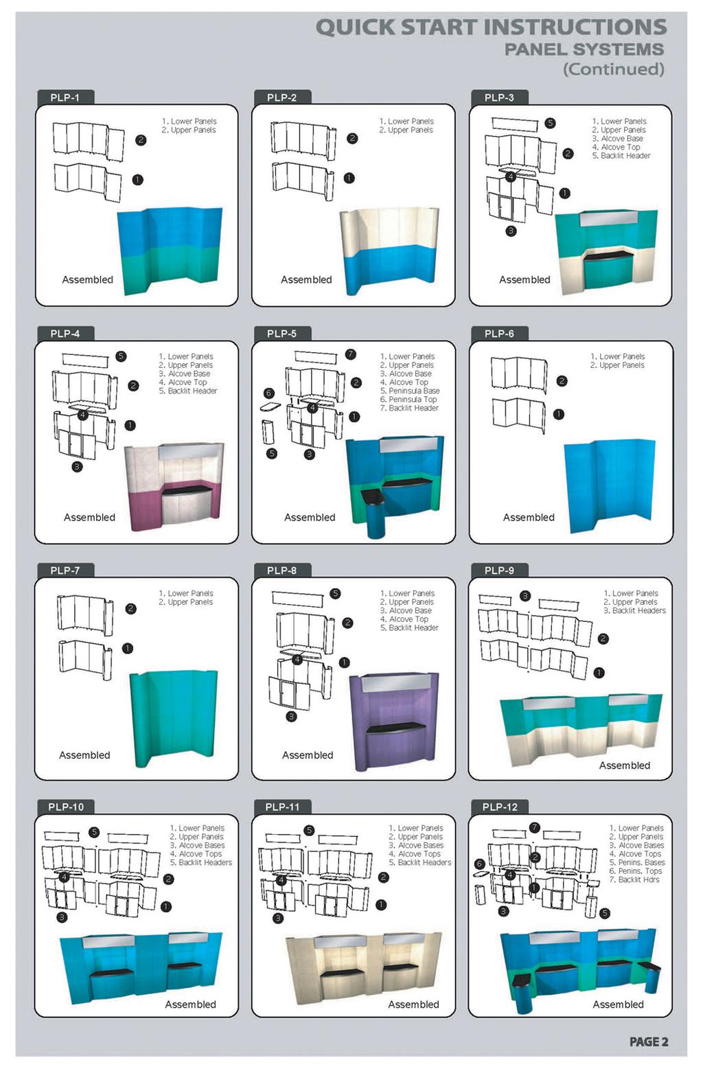
5 SECTION Quick Start: One page instructions for backwall and header assembly for a basic 10 unit. Component Assembly: Backwall, Curved Panels, ST8, TT6, RT, RDC, RSC, SDC, TDC Counter Assembly: A1, K1, C1,C2, D30/38, RC, RPC, SPC, TPC Table/Pedestal Assembly: RCT, P1, P2, RPC1/2, PR1/2 TABLE OF CONTENTS Page 1 Pages 2-11 Pages Pages NOTE: Instruction pages which apply to your display are marked with a colored label. Header Assembly: H2/3, HT 1/2, DC2P/3P, DC2/LF, DC3/LF, BH2/3, BH2/3 Angled Lightbox and Graphic Sconce Assembly: LBU/LBL, LBF, Double Panel LB, RSC1, RSC2 Pages Pages Miscellaneous Accessories: Plex Standoffs, MSTD, Tub Conversion, Hanging Abex 350 Truss Pages Packing, Care & Maintenance Pages 49-52
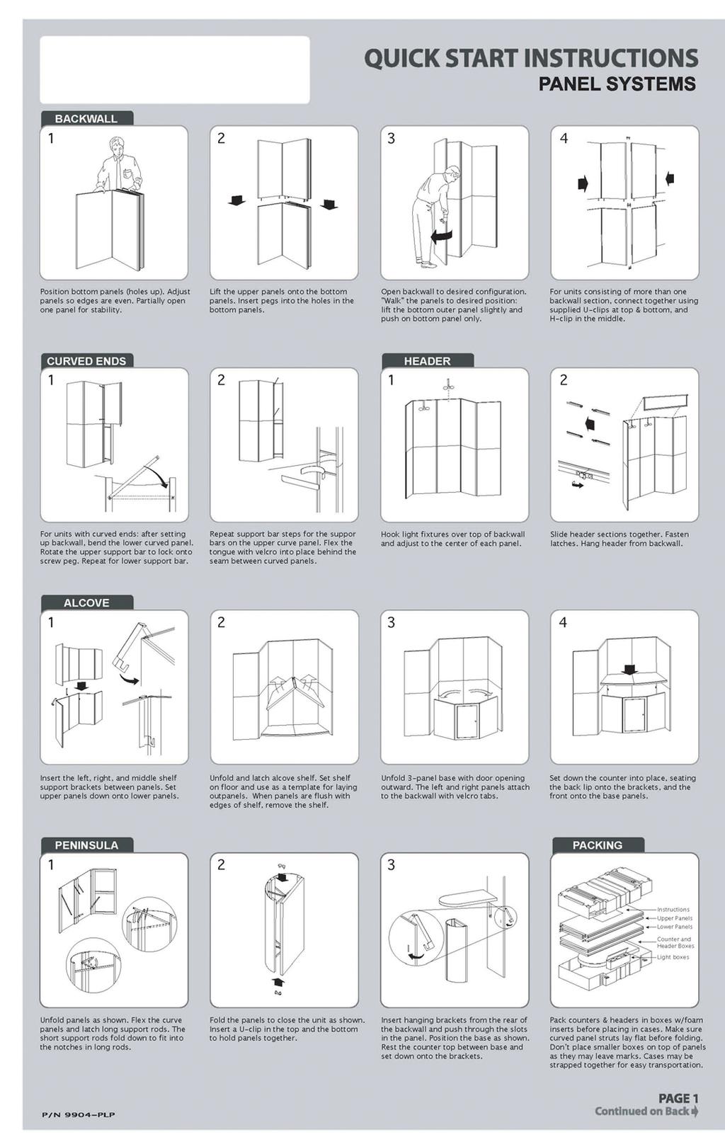
6 QUICK START Position bottom panels (holes up). Adjust panels so edges are even. Partially open one panel for stability. Lift upper panels onto bottom panels. Insert pegs in holes in bottom panels. Open backwall to desired configuration. Push on bottom of system only. Maintain right angle on one panel to ensure stability. Repeat steps for opposite side. Remember to maintain a right angle on the outer panels while opening system. Hook light fixtures over top of backwall. Slide header sections together. Fasten latches. Hang header from backwall. Attach H2 or H3 header to unit. Hang a pair of diffuser brackets from the top of the backwall adjacent to the light fixtures. Hang the left half of the diffuser from the left diffuser bracket. There is a slot in the diffuser's extrusion to accept the bracket. Hang the right half of the diffuser from the right bracket, and insert edge into the "H" moulding which is glued to the left half. Page 1 Swing header forward slightly, and raise diffuser. Lower diffuser so plastic strip on bottom of front edge fits inside the channel on the bottom of the header.
7 BACKWALL ASSEMBLY Position bottom panels (holes up). Adjust panels so edges are even. Partially open one panel for stability. Lift upper panels onto bottom panels. Insert pegs in holes in bottom panels. Open backwall to desired configuration. Walk the panels to desired position: lift the bottom outer panel slightly and push on bottom of system only. Maintain right angle on one panel to ensure stability while opening system. Page 2 For units consisting of more than one backwall section, connect together using supplied U-clips at top and bottom, and H- clip in middle.
8 CURVED PANELS After setting up backwall, bend lower curved panel. Rotate support bars to lock onto screw pegs. Repeat steps for all support bars. Flex tongue and velcro in place behind seam between panels. Page 3
9 ST8 SQUARE TOWER Unfold panels (with holes up). Fold panel sections to form squares. Fasten bottom section with a U-clip on the bottom and an H-clip on the top. Position top section (with pegs down) onto bottom section. Insert U-clip on top. Assembled unit. Page 4
10 TT6 TRIANGULAR TOWER Unfold panels (with holes up). Fold panel sections to form triangles. Fasten bottom section with U-clip on bottom and H-clip on top. Position top section with pegs down. Insert U-clip on top. Assembled unit. Page 5
11 RT RADIUS TOWER Unfold panels as shown. Flex curved panels and latch long support rods. Short support rods fold down to fit in notches in long rods. Stack the panel sections, fastening the ends of the curved panels to the flat panels with U-clips at the top and bottom and an H-clip in the middle. The upper flat panel has pegs on the bottom that fit into corresponding holes in the top of the lower panel. Assembled unit. Page 6
12 RDC1 RADIUS DISPLAY CASE - OPEN Unpack components and unfold panels. Flex curved panels and latch long support rods. Short support rods fold down to fit in notches in long rods. Attach the end of the curved panels to the flat panel with a U-clip at the top and bottom. Stack the upper flat panel on top of the lower one. It has pegs that fit in corresponding holes in the lower panel. Install a pair of support bars in the back. They have bolt heads that fit into keyhole slots in back of the panels. Push down firmly on support bars. Rest countertop on top of curved panels. Page 7
13 RDC2 RADIUS DISPLAY CASE - CLOSED Unpack components and unfold panels. Flex curved panels and latch long support rods. Short support rods fold down to fit in notches in long rods. Attach the end of the curved panels to the flat panel with a U-clip at the top and bottom. Stack the upper flat panel on top of the lower one. It has pegs that fit in corresponding holes in the lower panel. Install a pair of support bars in the back. They have bolt heads that fit into keyhole slots in back of the panels. Push down firmly on support bars. Page 8 Rest countertop on top of curved panels. Set up radius sconce, as explained on the next page, and hang from upper panel. Flex lexan window, and velcro in place between curved panels and sconce.
14 RSC RADIUS SCONCE Wrap sconce panels around diffuser, and latch long support bars. Diffuser should be held tightly in place. Short support bars fold down to fit in notches in long bars. Hang sconce from backwall. Page 9 Position ball light over hole in diffuser. Lower support bar will have to be unlatched to accommodate ball light.
15 SDC SQUARE DISPLAY CASE Unpack components and unfold panels. Fold bottom panel section into square, and fasten with U-clips at the top and bottom. Stack upper panel section on top. It has pegs on the bottom that correspond to holes on the top of the lower section. Position stabilizer bar. It's flanges go in grooves on top of the upper panels. Make sure base is "square". Insert 5 shelf support pegs into panels shown. Repeat for other panels excluding door panel. Set countertop and ceiling in place. Position ball light over hole in ceiling. Page 10
16 TDC TRIANGULAR DISPLAY CASE Unpack components. Fold bottom panel section into triangle, and fasten with U-clips at the top and bottom. Stack upper panel section on top. It has pegs on the bottom that correspond to holes on the top of the lower section. Position stabilizer bar. It's flanges go in grooves on top of the upper panels. Insert 5 shelf support pegs into the left panel as shown. Only 3 are used on the right panel, since the ones in the back would interfere with the ones on the left. Set countertop and ceiling in place. Position ball light over hole in ceiling. Page 11
17 A1 ALCOVE COUNTER - 2 PANEL BASE Insert left, right, and middle shelf support brackets between panels. Set upper panels down onto lower panels. Unfold and latch alcove shelf. Set shelf on floor and use as a template for laying out panels. When panels are flush with edges of shelf, remove the shelf. Set lower door track in place between alcove end panels. The panels attach to the backwall with velcro tabs. Set sliding doors in place, and insert upper door track. Rest counter in place. Page 12
18 A1 ALCOVE COUNTER - 6 PANEL BASE Unfold countertop and fasten latch on underside. Rest on floor, and use as a template to position the backwall panels at the proper angles. Remove countertop, and position 6 panel base as shown. The side panels fasten to the backwall with velcro tabs. Insert lower and upper door track. Rest countertop on base and position doors in place. Page 13
19 A1 ALCOVE COUNTER - HINGED BASE Insert left, right, and middle shelf support brackets between panels. Set upper panels down onto lower panels. Unfold and latch alcove shelf. Set shelf on floor and use as a template for laying out panels. When panels are flush with edges of shelf, remove the shelf. Unfold 3-panel base with door opening outward. The left and right panels attach to the backwall with velcro tabs. Rest counter in place. Page 14
20 A1 ALCOVE COUNTER - FREESTANDING Unfold countertop. Slide support bar onto bottom. It has keyhole slots that fit over the heads of bolts that stick out slightly. Lay countertop on floor, and use as a template to position the backwall panels at the proper angles. Insert 4 shelf support brackets into backwall as shown. Hang countertop from brackets. Page 15
21 K1 SQUARE KIOSK COUNTER Unpack components. Panels are marked on the inside which way is up. Arrange panels as shown. Fasten them together with the lower door tracks. Insert sliding doors, and upper door tracks. Unfold countertop, fasten latches on lower side, and rest on base. Page 16
22 C1 RECTANGULAR COUNTER Unfold panels to form front and sides of counter. Position bottom sliding door track. Rest inner shelf on rails on insides of panels. Position doors in bottom track and insert top track over them. Position countertop on unit. Page 17
23 C2 RECTANGULAR COUNTER Unfold panels to form front and sides of counter. Position inner shelf on rails on insides of panels. Position countertop. Assembled unit. Page 18
24 D30/D38 DESKS The D30 and D38 are identical, except for the height of the base. A D38 is pictured. To begin, unfold panels as shown. Flex curved panels and latch long support rods. Short support rods fold down to fit in notches in long rods. Fold panels to configuration shown. Fasten ends of curved panels to unit with U-clips on the top and bottom. Rest countertop on base. Page 19
25 RC w/ LIFT-OUT DOOR RADIUS COUNTER Unfold panels. Flex curved panels and latch long support rods. Short support rods fold down to fit in notches in long rods. Fold panels to configuration shown. Fasten ends of curved panels to unit with U-clips on the top and bottom. Position shelf. Insert upper and lower door tracks. Rest countertop on base and insert lift out door. Page 20
26 RC w/ HINGED DOOR RADIUS COUNTER Unfold panels. Flex curved panels and latch long support rods. Short support rods fold down to fit in notches in long rods. Fold panels to configuration shown. Fasten curved panels to unit with U-clips at the top and bottom in three locations (some lower clips concealed in image). Lower the shelf into place. Insert the upper and lower stabilizer bars. The flanges on the ends of the bars go into the grooves in the center of the panels. Rest countertop on base. Page 21
27 RPC1 RADIUS PENINSULA COUNTER Unfold panels as shown. Flex curved panels and latch long support rods. Short support rods fold down to fit in notches in long rods. Fold panels to close unit. Insert a U-clip in the top and bottom to hold panels together. Page 22 Insert hanging brackets from the rear of the backwall and push through slots. Position base as shown. Rest countertop between base and brackets.
28 RPC2 w/ LIFT-OUT DOOR RADIUS PENINSULA COUNTER NOTE: Some units may be mirror images of this one, with the door on the other side. Unfold panels as shown. Flex curved panels and latch long support rods. Short support rods fold down to fit in notches in long rods. Fold panels to configuration shown. Insert a U-clip in the top and bottom to hold the end of the curved panels in place. Insert the upper and lower door tracks. Install the shelf. Page 23 Insert hanging brackets from the rear of the backwall and push through slots. Position base as shown. Rest countertop on base and brackets. Insert lift out door.
29 RPC2 w/ HINGED DOOR RADIUS PENINSULA COUNTER NOTE: Some units may be mirror images of this one, with the door on the other side. Unfold panels as shown. Flex curved panels and latch long support rods. Short support rods fold down to fit in notches in long rods. Fold panels to configuration shown. Insert a U-clip in the top and bottom to hold the end of the curved panels in place (lower clip concealed in image). Lower the internal shelf into place. Insert the upper and lower stabilizer bars. The flanges on the ends of the bars go into the grooves in the center of the panels. Page 24 Insert hanging brackets from the rear of the backwall and push through slots. Position countertop on base and brackets.
30 RPC3 w/ SLIDINGDOORS RADIUS PENINSULA COUNTER NOTE: Some units may be mirror images of this one, with the door on the other side. Unfold panels as shown. Flex curved panels and latch long support rods. Short support rods fold down to fit in notches in long rods. Fold panels to configuration shown. Insert a U-clip in the top and bottom to hold the end of the curved panels in place (lower clip concealed in image). Lower the internal shelf into place. Insert the upper and lower stabilizer bars. The flanges on the ends of the bars go into the grooves in the center of the panels. Page 25 Place connector strips (2) between rear counter panel and backwall. Position countertop on base and brackets.
31 SPC w/ LIFT-OUT DOOR SQUARE PENINSULA COUNTER Unpack components. Fold panels to form 3 sides of base. Insert upper and lower door tracks. Install shelf. Insert lift out door. Page 26 Insert hanging brackets from the rear of the backwall and push through slots. Position base as shown. Rest countertop between base and brackets.
32 TPC TRIANGULAR PENINSULA COUNTER Unpack components. Fold panels to form triangle. Fasten with U-clips at the top and bottom. Insert hanging brackets from the rear of the backwall and push through slots. Position base as shown. Rest countertop between base and brackets. Page 27
33 RCT ROUND CONFERENCE TABLE Rest countertop on floor and unfold. Fasten latches to secure. Slide the base panels together. Position base panels over countertop with plastic feet facing up. Rotate base panels so metal brackets slide into the notches in the panels. Secure base panels to countertop with the attached velcro tabs. Turn table assembly upright. Page 28
34 P1 SQUARE PEDESTAL Unfold panel sections to form a square. Connect top and bottom with U-clips. optional door & shelf Insert the optional shelf. Place the upper and lower door tracks, then insert the optional door. Set top on base. Page 29
35 P2 TRIANGULAR PEDESTAL Fold panel sections to form a triangle. Connect top and bottom with U-clips. Place top on base. Assembled unit. Page 30
36 PR1/PR2 ROUND PEDESTALS Unpack components. Flex curved panels and latch long support rods. Short support rods fold down to fit in notches in long rods. Rotate curves to close circle, and fasten with U-clips at the top and bottom. Rest countertop on base. Page 31
37 H2/3 BACKLIT HEADER Hook light fixtures over top of backwall. Slide header sections together. Fasten latches. Hang header from backwall. Page 32
38 HT1/2 HEADER Hook light fixtures over top of backwall. Slide header sections together. Fasten latches. Hang header from backwall. Page 33
39 DC2P/3P DIFFUSER Attach H2 or H3 header to unit. Hang a pair of diffuser brackets from the top of the backwall adjacent to the light fixture brackets. Hang the left half of the diffuser from the left diffuser bracket. There is a slot in the diffuser's rear extrusion to accept the bracket. Hang the right half of the diffuser from the right bracket, and insert edge into the "H" moulding which is glued to the left half. Page 34 Swing header forward slightly, and raise diffuser. Lower diffuser so plastic strip on bottom of front edge fits inside the channel on the bottom of the header.
40 DC2L/F & DC3L/F DIFFUSER w/ BALL LIGHTS Attach H2 or H3 header to unit. Hang a pair of diffuser brackets from the top of the backwall adjacent to the light fixture brackets. Hang the left half of the diffuser from the left diffuser bracket. There is a slot in the diffuser's rear extrusion to accept the bracket. Hang the right half of the diffuser from the right bracket, and insert edge into the H moulding which is glued to the left half. Page 35 Swing header forward slightly, and raise diffuser. Lower diffuser so plastic strip on bottom of front edge fits inside the channel on the bottom of the header. Position ball lights over holes in diffuser.
41 BH2/3 BRIDGE HEADER Slide together the side sections of the headers, and fasten the latches. Hang headers between backwall and tower. Attach lights. Pegs on light brackets fit into holes in top of headers. Page 36 Insert diffusers so plastic strip on bottom of diffusers edges fit inside the channels on the bottoms of the headers.
42 BH2/3 ANGLED BRIDGE HEADER Slide together the side sections of the headers, and fasten the latches. Hang header sides between walls. Attach light fixtures. Be sure tabs on fixtures engage with holes on top of header frames. Rotate header sides to angled position and hook support bars onto screws to lock in place. Page 37 Install diffusers. The aluminum angles face down and fit in the channels on the bottom of the header sides. Tilt diffusers so they will fit through the opening, raise, and let drop into place.
43 LBL/LBU LIGHTBOX Remove trim strips around the front edges of the window. Once one side of the strip is loose, the rest comes off easily. A prying tool may be needed. A diffuser bracket is handy for this purpose. Flex reflector panel and insert into the back of the window. Hang light fixture from hole in reflector panel. Page 38 Insert the graphics into the window, sandwiched by a milk panel in the back, and a transparent panel in the front. Replace trim strips. When disassembling unit, first remove the reflector, and then the trim strips in the back. This way you will not scratch the transparent panel with your prying tool.
44 LBF LIGHTBOX Remove trim strips around the front edges of the window. Once one side of the strip is loose, the rest comes off easily. A prying tool may be needed. A diffuser bracket is handy for this purpose. Flex reflector panels and insert into the back of the window. Hang light fixtures from holes in reflector panels. Page 39 Insert the graphics into the window, sandwiched by a milk panel in the back, and a transparent panel in the front. Replace trim strips. When disassembling unit, first remove the reflector, and then the trim strips in the back. This way you will not scratch the transparent panel with your prying tool.
45 DOUBLE PANEL LIGHTBOX (30 x40 MAX) Remove right and left trim strips on the front edges of the window. Once one side of the strip is loose, the rest comes off easily. A prying tool may be needed. A diffuser bracket is handy for this purpose. Flex reflector panel, and insert into the back of the window. Hang light fixtures from holes in reflector panels. Page 40 Insert the graphics into the window, sandwiched by a milk panel in the back, and a transparent panel in the front. Replace trim strips. When disassembling unit, first remove the reflector, and then the trim strips in the back. This way you will not scratch the transparent panel with your prying tool.
46 RSC1 BACKLIT RADIUS SCONCE Wrap sconce panel around diffuser and latch support bars. Diffuser should be held tightly in place. Hang light fixture from backwall section where sconce will be installed. Drape power cord over back of unit and plug into extension cord or power strip. Hang sconce from backwall. Attach graphic with velcro. Page 41
47 RSC2 RADIUS SCONCE W/ BALL LIGHT Wrap sconce panel around diffuser and latch large support bars. Diffuser should be held tightly in place. Swing small support bars down and latch to large support bars Hang sconce from backwall Position ball light over hole in diffuser. Drape cord over back of panel. Page 42
48 RSL LAMINATE SCONCE Hold sconce with lights facing down and brackets to the back. Unroll power cord. Hang sconce on top edge of backwall panel. Drape power cord over back of unit and plug into extension cord or power strip. Steps 1 and 2 are the same for the triangle sconce. Steps 1 and 2 are the same for the quarter round and the 120 sconces. Page 43
49 PLEX STANDOFFS Unpack standoffs and plex. Before assembling, center graphic on frosted plex and attach with double-sided tape (not included). Push a threaded cap through the hole in backwall panel, then connect standoff and plex to backwall in the following order: standoff, frosted plex with graphic, clear plex, threaded cap. Repeat assembly for other standoffs. Finger-tighten only, as too much pressure will crack the plex. Assembled unit. Page 44
50 MSTD MONITOR STAND Expand monitor stand approx. 15 to 18 by pulling on any two adjacent legs. Hold down a single leg while lifting truss with other hand until snap button locks into place. Lock each upper support arm onto plastic receivers by pushing down. Adjust monitor stand to desired height by lifting leg and pulling out the inner leg until snap button locks. Repeat for other legs. Page 45 Unfold the top and place cutout areas over legs and press into place. Place the nonskid pad to prevent monitor from sliding. Position unit behind monitor cutout in backwall.
51 TUB CONVERSION Remove front cover of tub, and put it on the back. Fasten latches to secure. Rotate tub to rest on it's side. Unfold the 7 panel base, and wrap around 3 sides of tub. Insert lower and upper door track. Slide together the 3 sections of the countertop. Fasten the 4 latches on the underside (these are similar to the latches on the tub). Slide the support bar into place. It has 4 keyholes that fit over the heads of bolts in the bottom of the counter sections. Rest the countertop on the base. Position the doors. Page 46
52 HANGING ABEX 350 TRUSS VERTICAL ORIENTATION Expand the truss frame and lock all the spacer bars, as explained in the "Quick Start" section of the Abex 300 series Owner's Manual. Slide hanging brackets onto the hubs at the 4 upper corners of the truss. Hang the truss between the backwall and a display case or tower. (square tower shown) Page 47
53 HANGING ABEX 350 TRUSS HORIZONTAL ORIENTATION Expand the truss frame and lock all the spacer bars, as explained in the "Quick Start" section of the Abex 300 series Owner's Manual. Rotate frame so broad side faces floor. Slide hanging brackets onto the hubs at the 4 upper corners. Hang the truss between backwall sections. Page 48
54 PACKINGTIPS Use these tips as a guide to simplify your teardown and repacking. Pack countertops in boxes with foam inserts before placing in cases. Place clips and lights in appropriate boxes. Remove keys from locks before folding up panels. Remove plexiglas and snaptrack before folding up a backwall containing a double lightbox. Remove reflectors and lights from panel before collapsing. Make sure that any roseanne (threaded) inserts are facing the outside of the case. Make sure curved system panel struts are laying flat before folding. Panel pegs should be facing upward when packing in a tub. Do not place smaller counter top boxes on top of system panels as they may leave an indentation. Cases may be strapped together for easy transportation. Page 49
55 TRANSPORT CASE PACKINGDIAGRAM Owner s Manual Panels Countertop Boxes Lights Page 50
56 Place system panels with pegs up into large section of the tub TRANSPORT TUB PACKINGDIAGRAM Place Header & Countertop boxes into upper section Owner s manual is located in plastic folder Buckle straps after boxes are in place Lighting Boxes Page 51
57 CARE & MAINTENANCE Your Abex 600 MultiConnect display system is virtually maintenance-free. In order to insure that your display is always looking its best, we recommend these basic care procedures. Avoid placing system pegs on floor. Return display to room temperature before handling. Do not leave display in direct sunlight or trunk of your car. Do not subject display to extreme heat or cold. Store display upright at room temperature. Clean plexiglas with Bestine or equivalent to remove dust or dirt. Use a soft brush to restore fabric nap. Sponge off stains with mild household detergent or mild carpet cleaner spot remover. Page 52
POP PLUS / SPIDER SET-UP INSTRUCTIONS
 POP PLUS / SPIDER SET-UP INSTRUCTIONS 1 Place system frame on floor with screws indicating top. Expand upwards & outwards and secure frame connectors. Pop-Up display systems are made to be set-up and taken
1 Intro Folding Panel System 12 Panel Display Backwall Set-up Instructions 1. 2.
 1 Intro Folding Panel System 12 Panel Display Backwall Set-up Instructions Right Stack top panels on bottom panels Unfold display wall Set in desired configuration Wrong Pull from here Remove each folded
Product must be installed as shown using the screws and brackets provided. Use of incorrect hardware could result in damage to the product.
 General Notes These installation instructions are intended to be comprehensive for a typical Keyeira/Presto configuration. Your configuration may differ. If you have questions contact Geiger Customer Service
SETUP INSTRUCTIONS If you would like to tell us about your experience with your setup instructions please us at
 207 VK-964 General Layout 0 0 Plan View www.classicexhibits.com SETUP INSTRUCTIONS If you would like to tell us about your experience with your setup instructions please email us at info@classicexhibits.com
SETUP INSTRUCTIONS If you would like to tell us about your experience with your setup instructions please us at
 208 VK-233 General Layout 0 0 Plan View SETUP INSTRUCTIONS If you would like to tell us about your experience with your setup instructions please email us at info@classicexhibits.com 208 General Information
WHEN DISASSEMBLING ALUMINUM EXTRUSION, TIGHTEN ALL SETSCREWS AND LOCKS TO PREVENT LOSS DURING SHIPPING
 Order #XXXXX - VK-2921 - General Layout Step 1 10 20 Plan View Page 1 of 6 Order #XXXXX - General Information Step 2 Using Your Setup Instructions The Visionary Designs Setup Instructions are created specifically
PACLEASE Hybrid Sacagawea VK-1222 Display Instructions / PAGE 1 - General Layout
 PACLEASE Hybrid Sacagawea VK-222 Display Instructions / PAGE - General Layout 800-676-3976 425-556-95 4054 48th Ave. NE Redmond, WA 98052 0 0 Plan View PACLEASE Hybrid Sacagawea VK-222 Display Instructions
WHEN DISASSEMBLING ALUMINUM EXTRUSION, TIGHTEN ALL SETSCREWS AND LOCKS TO PREVENT LOSS DURING SHIPPING
 Order #xxxxx - Sacagawea - VK-23 - General Layout Step 0 Plan View 0 202 Page of 4 Order #xxxxx - Sacagawea - General Information Step 2 Using You Set-up Instructions: The Visionary Designs Set-up Instructions
IMPULSE G2/PULSE STATIC BRIDGE & RETURN MODULE. Drill. Desk Connecting. Outside by fastening the supplied wood screws from the HK-67 kit through the
 PART # 1608990 STATIC BRIDGE & RETURN MODULE 1. This sheet covers the steps to install a static bridge or return module with the FX no hinged access panel back option to a height adjustable freestanding
Assembly Instructions
 InTandem Table System November 20 InTandem Table System - Worksurface #4 x/" 4 wood screw power beam Tools Provided T-0 Extended Torx Driver T-25 Torx Driver Additional Tools Required Soft protective
IMPULSE G2/PULSE STATIC BRIDGE & RETURN MODULE. Drill. Desk Connecting. Outside by fastening the supplied wood screws from the HK-67 kit through the
 PART # 1608990 STATIC BRIDGE & RETURN MODULE 1. This sheet covers the steps to install a static bridge or return module with the FX no hinged access panel back option to a height adjustable freestanding
M10 x 75mm Sockethead Cap Screws. 5mm Fender Washer (12) Included - (8) Required. #10 x 2.5" PH Wood Screws. (30) Included - (24) Required
 Included - (8) Required. #10 x 2.5 PH Wood Screws. (30) Included - (24) Required") Door System Unit - Hardware Tools Included: (2) 2mm Allen Wrenches, (2) 3mm Allen Wrenches, (2) 4mm Allen Wrenches, (2) 6mm Allen Wrenches, and (1) 8mm T-Handle Allen Wrench Tools Required: Phillips Screwdriver,
Door System Unit - Hardware Tools Included: (2) 2mm Allen Wrenches, (2) 3mm Allen Wrenches, (2) 4mm Allen Wrenches, (2) 6mm Allen Wrenches, and (1) 8mm T-Handle Allen Wrench Tools Required: Phillips Screwdriver,
Assembly Instructions
 RoomScape Furniture System March 2013 - Bed Styles bed deck board bed deck board top cap top cap base glide middle side rail frame frame stacking device frame middle lower reinforcement side rail Single
Cellular Shades SLUMBERSHADE. with energy saving blackout sidetracks. Installation & Care Instructions
 Cellular Shades SLUMBERSHADE with energy saving blackout sidetracks Installation & Care Instructions 152725 B 9/14/2017 GETTING STARTED A few simple tools are required: - Measuring tape - Power drill,
Storage Cabinets 9000 Series Assembly Instructions
 Storage Cabinets 9000 Series Assembly Instructions Thank you for selecting Salsbury s storage cabinets. We are confident that the quality and construction of the cabinets will prove to be a good investment.
TOOLS REQUIRED: HARDWARE INCLUDED: 13MM FLAT WRENCH FOR LEVELING THE STRUCTURE RATCHET WITH 5MM HEX BIT FOR CORNER SCREWS ON TOP TRAVERSE BEAMS
 1 TOOLS REQUIRED: RATCHET WITH 5MM HEX BIT FOR CORNER SCREWS ON TOP TRAVERSE BEAMS 13MM FLAT WRENCH FOR LEVELING THE STRUCTURE RUBBER MALLET FOR INSERTING PANELS 8MM HEX BIT WITH EXTENSION FOR HEX BOLT
FlexFrame - Storage Components and Skins
 FlexFrame - Storage Components and Skins 1/4 Square Drive Ball-Point Hex-Bit Socket 1/8 Short Hex, 1-1/2 Overall Length McMaster Part # 54075A44 Table of Contents Topic Page Storage Components 2 General
Assembly Instructions
 Selling Station Assembly Instructions View from above without top A B C D Rounded finished corners on A & D Square unfinished 3-sides on B & C Selling Station Components (2) 2' x 6' Side s Have a channel
Assembly Instructions 10 X 10 Aluminum Frame Building
 Assembly Instructions 10 X 10 Aluminum Frame Building 27 97 9 8 47 36 74 52 10 10 X 10 Square Building W/ Dome Includes: The Steel Entry Door with a Dead Bolt Lock assembly and Aluminum Door Frame. Metal
Oxford Stalls Installation Instructions
 Oxford Stalls Installation Instructions RAMM Horse Fencing and Stalls 13150 Airport Hwy. Swanton, OH 43558-9615 1-800-434-8456 Rev. 8/15/17 Before You Start Typical stall sizes are 10 x 10, 12 x 12 or
Installation Instructions
 by Plato Woodwork Installation Instructions Plato Woodwork, Inc. 200 Third Street SW P.O. Box 98 Plato, MN 55370 www.platowoodwork.com 800.328.5924 SECTION GUIDE GETTING STARTED PAGE # Installation Methods...
WHEN DISASSEMBLING TIGHTEN ALL KNOBS TO PREVENT LOSS DURING SHIPPING 2008
 Cae Lynne - General Layout Step 1 Page 1 of 8 Cae Lynne - Backwall Assembly Step 1 Part Number 1 2 3A 3 4 Description Left w/ A10 Clamps Attached Middle Upper Curved Vertical w/ A10 Clamps Attached Upper
INSTALLATION AND CUSTOMER CARE INFORMATION FOR SC FREESTANDING STERILIZATION CENTERS
 INSTALLATION AND CUSTOMER CARE INFORMATION FOR SC144-200 FREESTANDING STERILIZATION CENTERS General Information: Many Artizan Design Free-standing Sterilization Centers are custom designed and built to
WHEN DISASSEMBLING ALUMINUM EXTRUSION, TIGHTEN ALL SETSCREWS AND LOCKS TO PREVENT LOSS DURING SHIPPING
 VK-044 - Order #xxxxx - General Layout Step 8.5.00 0 Plan View 0 Page of VK-044 - Order #xxxxx - General Information Step 8.5.00 Using Your Setup Instructions The Visionary Designs Setup Instructions are
ZAPF PANEL SYSTEM ASSEMBLY INSTRUCTIONS. It is recommended that the components be installed in the sequence of this assembly manual.
 ZAPF PANEL SYSTEM It is recommended that the components be installed in the sequence of this assembly manual. ASSEMBLY INSTRUCTIONS OFFICE FURNITURE FOR THE INFORMATION AGE Table of Contents INSTALLATION
compile system INSTALLATION GUIDE Updated January 2019
 INSTALLATION GUIDE Updated January 09 compile system Table of Contents Panels 0 Quick Connect Clips 0 Lock Clips 0 Panel Trims 0 Privacy Glass 0 Post Base Covers 04 Electrical 04 Power Distribution Harness
Interra Installation Manual
 Interra Installation Manual Instructions to install the Friant Interra panel system Friant & Associates, LLC Table of Contents Getting Started Introduction... 3 General Tools, Staging & Safety... 4 Before
INSTALLATION AND CARE INSTRUCTIONS
 INSTALLATION AND CARE INSTRUCTIONS Vertical Applications Honeycomb Shades 52 C8-10-3401 Rev 2/14 CONTENTS Introduction...2 Before You Begin...3 Vertical Application Parts Overview...4 Materials Required...5
a.k.a. casegoods instructions
 a.k.a. casegoods instructions a a.k.a. workwall installation IMPORTANT NOTES Failure to install product according to installation instruction will result in loss of warranty. Tools required for assembly
INSTALLATION AND CUSTOMER CARE INFORMATION FOR SC FREESTANDING STERILIZATION CENTERS
 INSTALLATION AND CUSTOMER CARE INFORMATION FOR SC120-200 FREESTANDING STERILIZATION CENTERS General Information: Many Artizan Design Free-standing Sterilization Centers are custom designed and built to
AIR MASTER SYSTEMS INSTALLATION GUIDE TABLE OF CONTENTS
 AIR MASTER SYSTEMS INSTALLATION GUIDE TABLE OF CONTENTS GENERAL INFORMATION...1 Freight Damage... 1 Repairing Paint Scratches...1 BASE CABINETS... 2 Drawer Removal and Reinstallation...2 Replacing Drawer
WHEN DISASSEMBLING ALUMINUM EXTRUSION, TIGHTEN ALL SETSCREWS AND LOCKS TO PREVENT LOSS DURING SHIPPING
 Order #xxxxx - General Layout Step 866.65.00 0 Plan View 0 Page of 6 Order #xxxxx - General Information Step 866.65.00 Using Your Setup Instructions The Visionary Designs Setup Instructions are created
Cellular SlumberShade
 Cellular SlumberShade with energy saving blackout sidetracks Installation Instructions 152110 1/6/2011 BASICS A few simple tools are required: - Measuring tape - Power drill, drill bits - Hex head and/or
RAMPAGE P R O D U C T S. INSTALLATION INSTRUCTIONS BRONCO ZIPPER FASTRACK TOP PART #984xx BRONCO TOOLS REQUIRED
 RAMPAGE P R O D U C T S 84 (+/- 1/4 ) INSTALLATION INSTRUCTIONS BRONCO ZIPPER FASTRACK TOP PART #984xx BRONCO 1966-1977 TOOLS REQUIRED 3/8 WRENCH 7/16 WRENCH ½ WRENCH #2 PHILLIPS SCREWDRIVER 1/8 DRILL
Germ City Storage Box Inventory
 Germ City Storage Box Inventory 4 Wide connector bars 11 Thin connector bars (4 with Velcro on one side) 12 Channel parts (6 with extensions) 1 Black fabric exhibit cover 2 Black decorated burlap panels
Right. Side Tower-Overhead Combination Revised 11/12/05 ON SITE A,B D,E C
 Right ON SITE Side Tower-Overhead Combination Revised 11/12/05 2 Installation of Side Tower-Overhead Combination units is easy when the correct SEQUENCE is followed. 3 Your unit consists of the following
Topo Freestanding Applications - Private Office
 4 3 2 Topo Freestanding Applications - Private Office Combo Wrench If you have a problem, question, or request, call your local dealer, or Coalesse at 1.800.627.6770 Or visit our website: www.coalesse.com
WHEN DISASSEMBLING TIGHTEN ALL BLACK KNOBS TO PREVENT LOSS DURING SHIPPING
 Order #xxxxx - P20 - Ben Jamin - General Layout Step Page of 8 Order #xxxxx - P20 - Ben Jamin - Backwall Assembly Step Part Number 1 2 3A 3 4 Description Left w/ A10 Clamps Attached Middle Upper Curved
Insolroll Clutch Operated Shades Installation Instructions Installation Instructions
 All clutch operated shades are shipped fully assembled and ready for installation. Mounting screws are not provided. Screws for chain guide installation to meet the child safety standards are provided.
For installation assistance, contact SARGENT at DOORS SHOWN HERE SWING IN FOR ILLUSTRATION PURPOSES ONLY.
 SARGENT Installation Instructions for LP8600 x LR8600 & 12-LP8600 x 12-LR8600 Series Low Profile Panic and Fire Exit Devices on Double Egress & Double Doors or LS8600 & 12-LS8600 Low Profile Exit Device
INSTALLATION INSTRUCTIONS CJ-5 M38A PART # With Doors
 INSTALLATION INSTRUCTIONS CJ-5 M38A1 1955-1975 PART #109-011 With Doors Thank you for purchasing Specialty s Convertible Top for your Jeep vehicle. It has been designed for great fit and long wear. Please
Corded Honeycomb Shades
 Corded Honeycomb Shades Remove shade from package. Save packaging until shade is installed and working to your satisfaction. Level Tape Measure Pencil Power drill Screwdriver s for different mounting surface:
PRE-ENGINEERED HORSE STALL SYSTEMS SDFD SLIDING DOOR c/w FOLD-DOWN GRILL. & Assembly. Installation Instructions
 PRE-ENGINEERED HORSE STALL SYSTEMS 4800 SDFD SLIDING DOOR c/w FOLD-DOWN GRILL & Assembly Installation Instructions 4800 SDFD Sliding Door c/w Fold-Down Grill Components - 1 3 /4" x 2" x 88" channels (2)
INSTALLATION: D1-NOTCH DRYWALL TRIM FLANGE
 T F W 604.549.979 604.549.9555 fluxwerx.com INSTALLATION: D1-NOTCH DRYWALL TRIM FLANGE fixture housing endcap kit optic kit join kit notch 2 cross section notch 4 cross section 4 4" 4-11/2" 4 /8 (111)
Linear Pro Kit 27. features and benefits: dimensions: additional information:
 Linear Pro Kit 27 LN-K-3P-27 Linear Pro Kits provide a modern, slick and stylish appearance. The extrusion based exhibits feature a Velcro-applied fabric center graphic, UV printed or frosted plex headers
MantelMount. TM1A Installation Instructions IMPORTANT SAFETY INSTRUCTIONS - SAVE THESE INSTRUCTIONS
 MantelMount TMA Installation Instructions IMPORTANT SAFETY INSTRUCTIONS - SAVE THESE INSTRUCTIONS TM Thank you for choosing the MantelMount television wall mount. Please read this entire manual before
Revised
 Indentify Non-powered panels and separate from Powered panels. Non-powered panel shown at left.. Powered panel shown at left has powerway mounted at factory. Also separate panels by surface type, width
2. Connect driver to power source leads. After connections are made, place driver above ceiling. SEE MINIMUM SPACE REQUIREMENTS BELOW.
 INSTALLATION INSTRUCTIONS INSTALLATION: 1. Cut proper opening in ceiling. Round: 140mm Ø, Square: 140mm x 140mm 140mm Ø 140mm x 140mm 2. Connect driver to power source leads. After connections are made,
Shetland Stalls Installation Instructions
 Shetland Stalls Installation Instructions RAMM Horse Fencing and Stalls 13150 Airport Hwy. Swanton, OH 43558-9615 1-800-434-8456 Rev. 1/9/18 Before you start Kit can accommodate up to 12 wide stall front
INSTALLATION AND CARE INSTRUCTIONS
 INSTALLATION AND CARE INSTRUCTIONS Vertical Applications Honeycomb Shades CONTENTS Introduction...2 Before You Begin...3 Vertical Application Parts Overview...4 Materials Required...5 Tools Required...6
Installation Instructions
 Installation Instructions Follow these simple instructions to install your OneDayCab! IMPORTANT: Unpack and check shipment for damage. Verify color, size and parts before demolition. Installation of interiors
LED Thin Frame Fixed Frame Screen User Guide
 LED Thin Frame Fixed Frame Screen User Guide INTRODUCTION INTRODUCTION WARNING - Sharp Edges This product may contain sharp edges, please handle with care. Protective gloves are recommended. WARNING -
HOUSE PARTS PACKED IN HOUSE BOX PARTS IN PLASTIC BAG (HARDWARE) PARTS IN SMALL PLASTIC BAG (FLOOR CLIPS) PARTS PACKED IN BUNDLE
 PARTS IN SMALL PLASTIC BAG (FLOOR CLIPS) PARTS PACKED IN BUNDLE") Check parts against this list before starting assembly. Refer to illustrations on pages 6 and 7 to view house parts. If any shortages are found, refer to Packing Slip for claim instructions. Item 3 5 6
Check parts against this list before starting assembly. Refer to illustrations on pages 6 and 7 to view house parts. If any shortages are found, refer to Packing Slip for claim instructions. Item 3 5 6
Cellular Shades CORD LOOP Standard Top Down - Bottom Up. Installation & Care Instructions
 Cellular Shades CORD LOOP ucontact@udoblinds.com 1-855-205-8442 Standard Top Down - Bottom Up Installation & Care Instructions GETTING STARTED A few simple tools are required: - Measuring tape - Power
Luxe Linen Honeycomb Shades
 Step by Step Installation Instructions Luxe Linen Honeycomb Shades Customer Service 800.248.8888 or visit us online at smithandnoble.com Table of Contents Getting Started...3 THANK YOU for purchasing from
Elara NanoEdge Fixed Frame Screen User Guide
 Elara NanoEdge Fixed Frame Screen User Guide INTRODUCTION INTRODUCTION WARNING This product may contain sharp edges, please handle with care. Protective gloves are recommended. A minimum of two people
Installation And Care Instructions. Vertical Honeycomb Shades
 Installation And Care Instructions Vertical Honeycomb Shades Rev 5/2013 Table Of Contents Getting Started... 3 Parts Overview... 4 Materials Required... 5 Tools Required... 6 Outside Mount Installation...
Linear Pro Kit 22. features and benefits: dimensions: additional information:
 Linear Pro Kit 22 LN-K-3P-22 Linear Pro Kits provide a modern, slick and stylish appearance. The extrusion based exhibits feature a Velcro-applied fabric center graphic, UV printed or frosted plex headers
System 3000 specifications
 System 3000 specifications Scope: Materials: Type of Bookstack: This specification covers delivery and installation of steel library shelving of the bracket type. Height, depth and accessories shall be
INSTALLATION INSTRUCTIONS
 INSTALLATION INSTRUCTIONS HIGH PRESSUE LAMINATE (HPL) TOILET PARTITIONS 1030 TrimLineSeries 1040 DesignerSeries Includes continuous hardware option.65. IMPORTANT: Storage and Handling Information on last
INSTALLATION INSTRUCTIONS
 INSTALLATION INSTRUCTIONS SOLID PHENOLIC TOILET PARTITIONS 1080 DuraLineSeries Class-A Fire Rated Includes Institutional Hardware Option.67 IMPORTANT: Storage and Handling Information on last page. Review
Formulate Accent Ladder 10
 Formulate Accent Ladder 10 FMLT-WL10 Formulate Master Accents enhance the functionality of many Formulate Master 10 and 20 backwalls and add more real estate for messaging too! With monitor supports, literature
End of Row Doors. Revision Number 1
 End of Row Doors Single Swing Door Café Style Doors Revision Number 1 Wright Line LLC 160 Gold Star Boulevard Worcester, MA 01606 Tel: 800-225-7348 508-852-4300 Fax: 508-365-6178 www.wrightline.com info@wrightline.com
CROWN IMPERIAL ASSEMBLY INSTRUCTIONS
 CROWN IMPERIAL ASSEMBLY INSTRUCTIONS Standard Drawer Box Page 1 of 14 Standard Drawer Box Parts Parts Supplied B C D A E F G Page 2 of 14 Part Letter Part Name Quantity 300-600 Deep Pan A Base Panel 1
Tradewinds Amplify Display System Instructions
 Table of Contents Packing & Unpacking... Standard Kits... Component Identification... Primary Components Vertical Pole Top... Vertical Pole Bottom... Horizontal... Cross/Hanging Bar... Amplify Shelf Package
INSTALLATION INSTRUCTIONS JEEP SCRAMBLER FAST TRAC TOP PART #108-21X
 INSTALLATION INSTRUCTIONS JEEP SCRAMBLER FAST TRAC TOP PART #108-21X Thank you for purchasing Specialty s Convertible Top for your Jeep vehicle. It has been designed for great fit and long wear. Please
INSTALLATION AND CARE INSTRUCTIONS
 INSTALLATION AND CARE INSTRUCTIONS Skylight Manually Operated Honeycomb Shades 20 C8-10-1806 2/15 1 INTRODUCTION Thank you for purchasing our product. Your new shade has been custom built for you from
HONEYCOMB & PLEATED Standard Shades Top Down Bottom Up
 HONEYCOMB & PLEATED Standard Shades Top Down Bottom Up INSTALLATION INSTRUCTIONS Rev. 8/2018 BASICS A few simple tools are required: Measuring tape Power drill, drill bits Hex head and/or Phillips driver
Joiner Kit For Models N388, C450, E402B, E411T, E415H, E440T, E442B, E521T and E522B
 Joiner Kit For Models N388, C450, E402B, E411T, E415H, E440T, E442B, E521T and E522B KIT COMPONENTS Part Illustration Description Rear Bracket Front Lower Bracket Front Upper Bracket KIT APPLICATION This
Therma-Tru Door Gallery Setup Instructions Swing Unit with Hardware Kit - Hardware Part # MADGSWU15 (Swing Unit) Part # MADGHKSU10 (Hardware Kit)
 Part # MADGHKSU10 (Hardware Kit)") Swing Unit with Hardware Kit - Hardware Tools Included: 4mm Allen Wrench, 6mm Allen Wrench, 8mm T-Handle Allen Wrench (1) 3/4" Drill Bit, (1) 7/32" Drill Bit and Hole Template Guide Tools Required: Phillips
Swing Unit with Hardware Kit - Hardware Tools Included: 4mm Allen Wrench, 6mm Allen Wrench, 8mm T-Handle Allen Wrench (1) 3/4" Drill Bit, (1) 7/32" Drill Bit and Hole Template Guide Tools Required: Phillips
ASSEMBLY INSTRUCTIONS FOR SL500A AND SL500AL
 ASSEMBLY INSTRUCTIONS FOR SL500A AND SL500AL January 2013 The SL500A is a square upright glass cabinet with a single hinged lockable door. It has five adjustable shelves plus the base. It also has an optional
Installation Instructions Supertop with Tinted Side and Rear Windows
 Installation Instructions Supertop with Tinted Side and Rear Windows Vehicle Application Jeep Wrangler (JK) 2007 Current Part Number: 54716 www.bestop.com - We re here to help! Visit our web site and click
Vertical Honeycomb Shades
 Step by Step Installation Instructions Vertical Honeycomb Shades Customer Service 800.248.8888 or visit us online at smithandnoble.com Thank you for purchasing from Smith+Noble. Your new shades have been
C L A S S I C. Deluxe. Snow Thrower Cab. Assembly and Care Instructions
 C L A S S I C Deluxe Snow Thrower Cab Assembly and Care Instructions Deluxe Snow Thrower Cab Assembly and Care Instructions Before you begin please unpack the carton and check that you have all your parts.
Installation Instructions
 Installation Instructions 000964 Revision F Installation Instructions for PIRIT Read this manual fully prior to starting installation. Call American eating Customer ervice with any questions. What you
RAMPAGE P R O D U C T S. BRONCO ZIPPER FASTRACK TOP PART #984xx BRONCO TOOLS REQUIRED
 RAMPAGE P R O D U C T S 84 (+/- 1/4 ) BRONCO ZIPPER FASTRACK TOP PART #984xx BRONCO 1966-1977 TOOLS REQUIRED 3/8 WRENCH 7/16 WRENCH ½ WRENCH #2 PHILLIPS SCREWDRIVER 1/8 DRILL BIT 9/64 DRILL BIT 5/32 DRILL
Interactive Monitor Arm
 Interactive Monitor Arm Tools Required -5mm Allen wrench -Phillips screwdriver -Plastic mallet There are two ways to attach a Monitor Arm to a Full Frame; with a Beam, or with a Post Mount. Both methods
Section 1 Safety working at height
 Contents Section 1 Safety working at height. Section 2 Hi-Step package contents & parts identification. Section 3 Assembly. Section 4 Operation. Section 5 Maintenance. Section 6 Extender package contents
The Castle House Assembly Instructions By Laser Dollhouse Designs
 The Castle House Assembly Instructions By Laser Dollhouse Designs HOUSE PARTS First floor slots labeled 1A-1G First floor Walls labeled 1A-1G First floor interior door frames (4) Wall 1A frames (6) Main
Read Below! Read Below! Read Below! Read Below! Read Below! Read Below! STOP READ TIPS BELOW TO MAKE ASSEMBLY MUCH EASIER
 Read Below! Read Below! Read Below! Read Below! Read Below! Read Below! STOP READ TIPS BELOW TO MAKE ASSEMBLY MUCH EASIER Here are some guidelines to help make assembling your unit much easier: -Read and
INSTALLATION GUIDE 2009-CURRENT HUMMER H3T PRODUCT CODE:
 INSTALLATION GUIDE 2009-CURRENT HUMMER H3T PRODUCT CODE: 268 June 22, 2010 TOOLS NEEDED COMPONENTS INCLUDED P2 Tip 3/8" Drill Rubber Gasket(s) x 2 Bracket(s) x 2 1/2" Drill Bit Bulkhead Flange #2 Phillips
Angled Side Flush with Panel Face
 Identify and sort panels by like sizes, fabrics, surface type (tackable vs hard), and NON- POWERED vs POW- ERED. Non-powered panels ship without a powerway. Powered panels include a powerway. See below.
ROS-APT Caucus Plinth Table with Trough Note: Details apply, however the actual configuration of your table may vary from what is depicted here.
 ROS-APT Caucus Plinth Table with Trough Note: Details apply, however the actual configuration of your table may vary from what is depicted here. Parts List - Tables Tops, Top Insert Panels and Base panels
Deluxe Exterior Solar Shades
 Deluxe Exterior Solar Shades Installation Instructions Email: customerservice@blindster.com Call us: (888) 256-8672 Mon - Fri 8am - 7pm (CT) Thank you for purchasing Deluxe Exterior Solar Shades from Blindster.
INSTALLATION GUIDE FOR METAL LABORATORY CASEWORK
 LABORATORY Casework & Cabinets INSTALLATION GUIDE FOR METAL LABORATORY CASEWORK RDM Industrial Products, Inc. RDM LAB CABINET INSTALLATION GUIDE TABLE OF CONTENTS GENERAL INFORMATION...1 Freight Damage...1
TABLE OF CONTENTS Missouri Over There / Traveling Exhibit
 TABLE OF CONTENTS 1 Packing List 2 Floor Plans 3 Setup Directions 4 Case Contents PACKING LIST PACKING LIST case description weight dimensions 1A 5 - Graphic Panels 4 - Magnetic Struts 1 - Setup Book (in
Parts list continues on Page 2 HOUSE PARTS PACKED IN HOUSE BOX PARTS IN SMALL PLASTIC BAG (HARDWARE) POST PARTS PACKED IN THIS BOX (LARGE PLASTIC BAG)
 POST PARTS PACKED IN THIS BOX (LARGE PLASTIC BAG)") Form 05-07 Instructions and Parts List MSS- Martin Safety System NOTES: () A complete system is packed in two boxes post box and house box. House box contains hardware for both post and house assembly.
Form 05-07 Instructions and Parts List MSS- Martin Safety System NOTES: () A complete system is packed in two boxes post box and house box. House box contains hardware for both post and house assembly.
Owner s Manual #TSGUARD
 Owner s Manual #TSGUARD PSI Table Saw Dust Collection Guard The ideal solution for table saw dust control. Version 3, 02/04 2004 PSI Woodworking Products 9900 Global Rd., Philadelphia, PA 19115 WARRANTY
INSTALLATION GUIDE. TRANZFORM Sound TRANZFORM Space
 INSTALLATION GUIDE TRANZFORM Sound TRANZFORM Space Cornell Iron Works, Inc. 100 Elmwood Ave. Crestwood Industrial Park Mountain Top, PA 18707 Phone: 800.233.8366 or 570.474.6773 Fax: 800.526.0841 INSTALLATION
LIGHT FIXTURES MUST BE COMPLETELY INSTALLED PRIOR TO CEILING CONSTRUCTION
 CAUTION: BEFORE BEGINNING INSTALLATION REVIEW LAYOUT DRAWINGS, AND SHIPMENT. MAKE SURE ALL LIGHT S AND MATERIALS ARE ON SITE AND READILY ACCESSIBLE. IF ANY ICON MATERIALS ARE MISSING, CONTACT ICON INTERNATIONAL
INSTALLATION INSTRUCTIONS
 INSTALLATION INSTRUCTIONS BRONCO FAST TRAC TOP PART #331-210 BRONCO 1966-1977 Thank you for purchasing Specialty s Convertible Top for your Bronco. It has been designed for great fit and long wear. Please
Installation Operation Care
 Installation Operation Care Palm Beach Polysatin Shutters CONTENTS Getting Started Installation Overview...1 Unpacking...1 Tools and Materials Needed...1 Fasteners...2 Frame Assembly Assemble the Frame
INSTALLATION INSTRUCTIONS
 HONEYCOMB & PLEATED Lift & Lock Cordless Lift Systems Standard Top Down/ Bottom Up INSTALLATION INSTRUCTIONS Revised 8/2018 Getting Started A few simple tools are required: - Measuring tape - Carpenters
======================================================================================== ( DR / DR) JK WRANGLER MOD RACK
 JK WRANGLER MOD RACK") (10984 4DR / 10982 2DR) JK WRANGLER MOD RACK INSTALLATION SHEET Important Notes: Some brands of windshield light brackets and snorkels may not be compatible with the 10984 MOD Rack System. Body lifts are
(10984 4DR / 10982 2DR) JK WRANGLER MOD RACK INSTALLATION SHEET Important Notes: Some brands of windshield light brackets and snorkels may not be compatible with the 10984 MOD Rack System. Body lifts are
Pleated Shades with Corded Top Down / Bottom Up Option
 Pleated Shades with Corded Top Down / Bottom Up Option Installation Instructions Email: customerservice@blindster.com Call us: (888) 256-8672 Mon - Fri 8am - 7pm (CT) Congratulations on purchasing Pleated
Mirage Installation Manual
 Mirage Installation Manual General Information This installation manual provides necessary information for the safe installation of the Mirage product. WARNING: Failure to follow the instructions in this
Acousti-Seal. Paired Panel. Encore Owner s Manual
 Acousti-Seal Encore 932 912 Paired Panel OPERATING AND MAINTENANCE INSTRUCTIONS FOR OPERABLE WALL SYSTEMS MODELS: ENCORE PAIRED PANEL, 932, 912 Safety Precautions Clear path of partition before moving
INSTALLATION INSTRUCTIONS
 POST THIS WARNING IN A CONSPICUOUS PLACE, CLEARLY VISIBLE TO ALL STORE PERSONNEL Install all components according to installation instructions. READ BEFORE ASSEMBLING WARNING FOR YOUR SAFETY Installation
This instruction manual is an in-depth look and explanation of how to assemble and install the Murphy Bed properly and efficiently.
 This instruction manual is an in-depth look and explanation of how to assemble and install the Murphy Bed properly and efficiently. Don t be put off by the size of the instruction manual as the large diagrams
LAN Locker Adjustable Shelves
 Adjustable Shelves LAN LOCKER ADJUSTABLE SHELVES * Adjustable Shelves are available for LAN LOCKER widths: 24, 30, 48, 60, and 72. * When installing more than one Adjustable Shelf, it is recommended that