K3MSB Hammarlund HQ-120-X CW/AM Receiver
|
|
|
- Russell Edwards
- 5 years ago
- Views:
Transcription

1 K3MSB Hammarlund HQ-120-X CW/AM Receiver My Hammarlund HQ-120-X was a 2002 Christmas present from my Elmer Milt Moratis W3XX (ex K3AMI) of Pittsburgh PA. Thanks Milt!! I clearly remember that summer day back in 1973 when at age 15 I rode my 3 speed Stingray bike to Perrysville Elementary School, where Milt was the principal, to take my Novice Exam!!

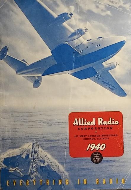
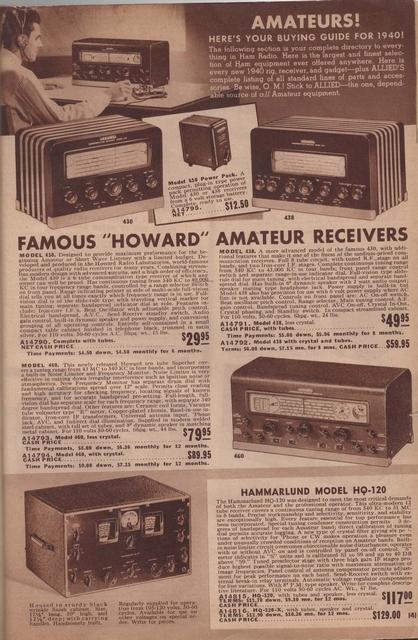
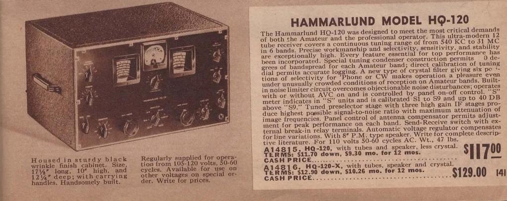
2 The HQ-120-X Communications receiver was produced between 1938 and It is a single conversion receiver covering 0.54 to 31 Mc in 6 bands. Here's the receiver advertised on page 141 of the 1940 Allied Radio catalog:
3
4


5 $129 In 1940 is about $2,225 in 2017! Just for some trivia, the 1939 median monthly salary for an engineer with 1 year of experience was about $128; 10 years of experience was about $250; and for 30 years of experience: $425 per month! Feb 5, 2015 Restoration started. March 27, 2015 Half of the chassis underside has the components replaced. Here's some before and after pictures. I trued to reuse as many of the resistors as I could but not many were within tolerance. Click on images to enlarge.


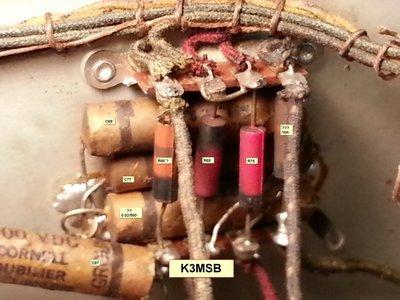
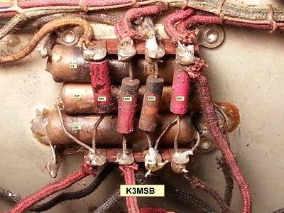
6 Some of the chassis holes that wires pass through have grommets and some do not. Some of those wires are pulled tight against the holes, and the insulation is 75 years old! I unsoldered those wires and slipped some heat shrink around the portion that passed through the chassis holes. It can be a tight fit, and in some cases I had to use a dental pick to gently persuade the heat shrink to go into the hole! Here's the before and after pictures of the components in the RF Cage.
 that go through chassis")

7 Surprisingly R7 (500K) was completely open. Note there are two wires (with that 75 year old insulation) that go through chassis holes with no grommets. I replaced those wires and routed them so that they do not have tension against the hole sides. While inside the RF cage I reflowed all the solder connections. Next up The other side of the chassis!

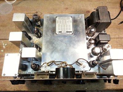
8 June 1, 2015 Here's how the right side of underneath the chassis looks. The power transformer and chokes have all been removed, as well as the audio bypass cap and 3 stage filtering cap. I need to replace the 3 remaining paper caps, and I'll do that when I run the new (3 conductor) line cord.

9 I'm trying to convince myself that the ON/OFF part of the AF Gain switch is OK. If I gently pull on the back I get about 30 ohms resistance at times when the switch is ON, so I'll have to keep that in mind. The next item I worked on was the Crystal Filter. As the following photo shows, you can access the inside of the filter by removal of a side plate, but you can not get to R113 and access to the one end of the 0.02 uf capacitor is not easy. It is best to just remove the assembly from the chassis, which fortunately is pretty easy. First remove the front panel. All the controls are secured to the chassis by nuts under the front panel and are not effected by the removal of the panel itself.


10 Next, unsolder the three wires under the chassis coming from the Crystal Filter. Finally, gently remove the filter and remove the top and side panels.
 is Y101, the 455 Kc crystal.")
11 Here's a close up of the "innards" of the Crystal Filter. The resistor at the bottom of the photo is R113. The large white rectangle at the left (really the top of the filter) is Y101, the 455 Kc crystal. Here is a more detailed photo of the parts placement in the Crystal Filter subassembly, along with an annotated version of Figure 2 from the Hammarlund manual:


12 I think three of the five resistors needed replaced, and of course the cap was replaced. When done, clean everything, put the top and side panels on, and remount on the chassis!


13 While the Crystal Filter was fun to work on, the next item wasn't. That was the big rust area on the chassis under the power transformer. Typically for rust that's not bad, I use Naval Jelly followed by a good cleaning with water, followed by a polishing with Never Dull. Afterwards, I apply a nice coat of Turtle Wax. I've used this method for years and it's provided me with a nice looking chassis and no return of rust. For this area, it took more than a few applications of Naval Jelly. The top surface of the chassis was gone and the chassis discolored. While this was the condition of small areas on the other side of the chassis, I decided to apply a coat of Rust-oleum Crystal Clear Enamel spray. It's good for up to 200F, and I doubt the chassis surface is going to get that hot. This was my first attempt to spray seal a chassis. Here are photos of the original rusted area before and after application of Naval Jelly and Never Dull: Now the radio is taped for spraying, and finally the end result:


14 Yes, the chassis is discolored where the rust used to be, but there's nothing to be done about that. Well! Getting close to smoke time! Just a few more odds and ends to reinstall, such as the new (original) power tranfromer, chokes, filter and audio caps, replace the dials... Stay tuned! September 10, 2015 It works! At long last, I drove the radio on the air a few days ago!

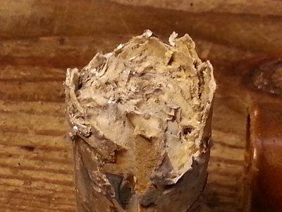
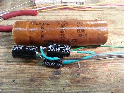
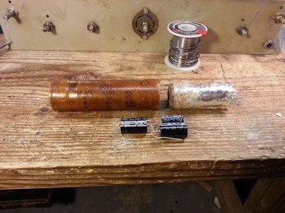
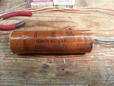
15 The first order of business, since the June 1st update, was to install the "new" audio and power transformers, as well as a three conductor power cable and associated safety capacitors. As the left image shows, I tried to save the original wire snippets that went to the two filter chokes and the filter capacitor. In the end, it was easier to just remove them and have those sockets basically cleaned and empty. A big tip of the hat to Dennis W7TFO who provided these transformers as well as the new dials for my radio! I decided to restuff the 3 section filter capacitor (C79) as well as the AF Amplifier cathode bypass capacitor (C103). Here's the filter capacitor...
16
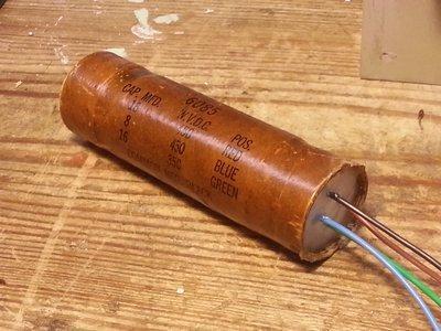
17

18 ...and here's the AF Amplifier bypass capacitor: Here's a diagram of the filter capacitor / choke section: The new dials are installed! There is a split-gear with spring tensioning for the main and bandspread tuning shafts. They were very easy to adjust.


19 Next, I installed the two filter chokes, the filter capacitor, replaced the remaining wax paper caps, out of tolerance resistors, etc. The end result:
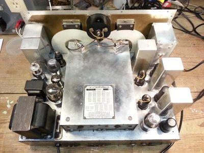
20


21 For my initial on the air testing I did not use any matching between the radio and my 50 ohms antennas. Signals were strong on 80, 40, and 20M. There was no activity on 10M so I pumped 5W into a dummy load and the receiver picked it up just fine. CHU Canada was loud and clear! I think I'm going to wind a 9:1 balun as the antenna expects 400 to 600 ohms and most of my antennas are 50 ohms. I was very pleased to see the Crystal Filter / Phasing worked nicely. I'm glad I took the time to remove that sub-assembly and replace the caps and out of spec resistors inside it. I'm not sure I'm going to do a full alignment on the radio. I want to actualy use it on the air for a while before deciding. Component Location Diagrams
. As should be obvious, no warranty expressed or implied in these diagrams.")

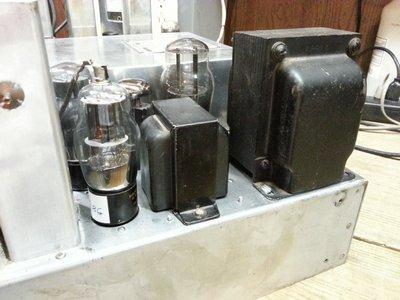
22 Here are some more detailed component placement photos for my radio (yours may be different). As should be obvious, no warranty expressed or implied in these diagrams... If you look at the left side of the chassis (left photo above), there are two "square" areas of components. I've called these the Front Square and Rear Square as shown below:

23 FRONT Square: REAR Square:

24 Sept 12, st QSO -- K4IBZ on 20M CW!! Great sensitivity on 20M today, and the Crystal Filter is working FB OM! Copyright (c) Mark S. Bell
You Just Brought an Old Radio Home: Now What Do You Do?
 You Just Brought an Old Radio Home: Now What Do You Do? Raymond Cady goldenageradiorestoration.com Whether you are just beginning to collect antique radios or you have been at it for a number of years,
 file:///c /BoatAnchors/Hammarlund/HQ170A/HQ170SVC.TXT Dear OM: This form is being prepared to provide prompt attention to a complaint as a result of trouble that may be experienced in the field. In addition
Manual Version July 2007
 Manual Version 1.2 - July 2007 Page 1 Table of Contents Section1: M3 Phono Board Build...3 Phono Board Parts List...3 Preparation...4 Fitting the Valve Bases...6 Installing the Resistors...7 Starting the
Assembly Instructions for the 1.5 Watt Amplifier Kit
 Assembly Instructions for the 1.5 Watt Amplifier Kit 1.) All of the small parts are attached to a sheet of paper indicating both their value and id. 2.) Leave the parts affixed to the paper until you are
Connecting the FCC-2 to the Hendricks DC Kits Bob Okas, W3CD
 Connecting the FCC-2 to the Hendricks DC Kits Bob Okas, W3CD This is an application note that describes how you can connect the NorCal FCC-1/2 combination to the DC kits. It involves a few extra components
New Life for the AM6154 and AM6155 John, W1AN 29 July, 2014
 New Life for the AM6154 and AM6155 John, W1AN 29 July, 2014 There are numerous sources for conversion information and modifications that have been shared over the years for the FAA AM6154 and AM6155 amplifiers
A 100-Watt Transmitter Using a Pair of VT1625s
 12/16/2007 6:00 PM VT1625 100 Watt Transmitter A 100-Watt Transmitter Using a Pair of VT1625s FIG. 10.6 A 100-watt transmitter for five bands, using salvaged TV power transformer and surplus 1625 amplifier
RITEK RIT for Collins KWM-2/2A 10/01/2002
 RITEK RIT for Collins KWM-2/2A 10/01/2002 The RITEK RIT (receiver incremental tuning) control was developed for KWM-2/2A in 1992 to "clarify" received signals differing from the transmit frequency indicated
Assembly Instructions for the FRB FET FM 70 Watt Amp
 Assembly Instructions for the FRB FET FM 70 Watt Amp 1.) Orient the circuit board with the diagram 2.) Use a narrow chisel tip 25-30 watt soldering iron for assembly 3.) All the small parts are taped onto
D ELCO. electronic parts AUTO RADIO BULLETIN. Connect Signal Generator to
 D ELCO electronic parts AUTO RADIO BULLETIN Bulletin 6D-864 Date 10-15-56 Page 1 FIRST ISSUE SUBJECT: SERVICE INSTRUCTIONS - CHEVROLET CUSTOM DELUXE WITH PUSH BUTTON TUNING - MODEL 987575 GENERAL M O U
The Uniden Grant XL Owners Site
 The Uniden Grant XL Owners Site Modifications page for the Grant XL (For Informational purposes only) The author of this site takes NO responsibility for illegal modifications and/or use of illegally modified
A 75-Watt Transmitter for 3 Bands Simplified Shielding and Filtering for TVI BY DONALD H. MIX, W1TS ARRL Handbook 1953 and QST, October 1951
 A 75-Watt Transmitter for 3 Bands Simplified Shielding and Filtering for TVI BY DONALD H. MIX, W1TS ARRL Handbook 1953 and QST, October 1951 The transmitter shown in the photographs is a 3-stage 75-watt
RadiØKit Μ CW HAM RADIO TRANSCEIVER KIT. Assembly and operating manual
 RadiØKit-120 20Μ CW HAM RADIO TRANSCEIVER KIT Assembly and operating manual Boreiou Ipirou 78 Kolonos Athens- Greece - 10444 Tel: 210.5150527 210.5132673 www.freebytes.com Thank you for buying RadiØKit-1,
Using Ferrite Beads Keep RF Out of TV Sets, Telephones, VCR's Burglar Alarms and other Electronic Equipment
 Using Ferrite Beads Keep RF Out of TV Sets, Telephones, VCR's Burglar Alarms and other Electronic Equipment RFI and TVI have been with us for a long time. Now we have microwave ovens, VCR's and many other
UNITED MOTORS SERVICE D IV ISIO N OF GENERAL M O TO RS C O R P O R A T IO N. General Offices - Detroit AUTO RADIO BULLETIN
 UNITED MOTORS SERVICE D IV ISIO N OF GENERAL M O TO RS C O R P O R A T IO N General Offices - Detroit AUTO RADIO BULLETIN Bulletin 6D-855 Date 11-1-54 Page 1 FIRST ISSUE SUBJECT: SERVICE INSTRUCTIONS -
Restoring an Atwater Kent Model 84. by Al Smith 25 Stonehedge Rd. Lincoln, MA 01773
 Restoring an Atwater Kent Model 84 by Al Smith 25 Stonehedge Rd. Lincoln, MA 01773 I recently restored an Atwater Kent model 84 for a non-technical friend. In the process, I ran into a number of problems,
Some KWM-2/2A Tricks. January By Georges, F6CER CCAE# 098. Some KWM-2/2A Tricks -
 Some KWM-2/2A Tricks January 2016 By Georges, F6CER CCAE# 098 Some KWM-2/2A Tricks Most of the KWM-2 transceivers that can be found in Europe belong to the first generation manufactured at the beginning
SoftRock v5.0 Builder s Notes. December 12, Building a QSD Kit
 SoftRock v5.0 Builder s Notes December 12, 2005 Building a QSD Kit Be sure to use a grounded tip soldering iron in building the QSD board. The soldering iron needs to have a small tip, (0.05-0.1 inch diameter),
MI: (Secure this number someplace, for possible future need) SPECIFICATIONS:
 SPECIFICATIONS:") 6C ASSEMBLY INSTRUCTIONS ANTENNA MODEL T6 MI: 030927 (Secure this number someplace, for possible future need) SPECIFICATIONS: FORWARD GAIN 5.1 dbd F:B RATIO 15-25 db (Rises with frequency) FREQUENCY COVERAGE
6C ASSEMBLY INSTRUCTIONS ANTENNA MODEL T6 MI: 030927 (Secure this number someplace, for possible future need) SPECIFICATIONS: FORWARD GAIN 5.1 dbd F:B RATIO 15-25 db (Rises with frequency) FREQUENCY COVERAGE
Modifying The Heath HA-14 For 6 Meters Greg Chartrand - W7MY 4/22/07
 Introduction The Heathkit HA-14 was one of the few electron tube linear amplifiers intended for mobile use but few were purchased with the 12 volt mobile power supply. Most hams bought the HA-14 for base
The Wireless-Set-No19 Group Royal Signals
 The Wireless-Set-No19 Group Royal Signals www.royalsignals.org.uk Joining The Wireless-Set-No19 Group and its e-mail reflector are FREE - CLICK HERE to join. The WS 19 Established & Designed in England
Starving Student II. Starving Student II. SS2 guide. Written By: 6L guides.diyaudio.com/ Page 1 of 24
 SS2 guide Written By: 6L6 2019 guides.diyaudio.com/ Page 1 of 24 INTRODUCTION This is a build guide for the hybrid headphone/pre-amplifier. You can buy a kit at the SSII product listing on the diyaudio
RF Current Meter Kit
 Kit When assembled, this kit provides you with a simple but effective means of measuring the current in antenna wires, and of looking for braid currents on coax feeders. The more current you can get flowing
The Wave (K-MOD103) GUITAR DWELL REVERB REVERB SWITCH ON OUT OFF
 GUITAR DWELL REVERB REVERB SWITCH ON OUT OFF") The Wave (K-MOD103) OUT IN GUITAR IN DWELL REVERB REVERB SWITCH ON GUITAR OUT POWER ON OFF OFF Please note, there are no labels for this kit. The controls, switches and connectors have only been labeled
The Wave (K-MOD103) OUT IN GUITAR IN DWELL REVERB REVERB SWITCH ON GUITAR OUT POWER ON OFF OFF Please note, there are no labels for this kit. The controls, switches and connectors have only been labeled
HOM rev. new Heathkit of the Month #79: by Bob Eckweiler, AF6C. Heath of the Month #79 - VF-1 VFO AMATEUR RADIO - SWL
 Heathkit of the Month #79: by Bob Eckweiler, AF6C AMATEUR RADIO - SWL Heathkit VF-1 External VFO (Variable Frequency Oscillator). Introduction: In 1951 the FCC totally revamped the license classes for
Manual AMERITRON QSK-5PC T/R SWITCH PC BOARD INTRODUCTION
 Manual Instruction AMERITRON QSK-5PC T/R SWITCH PC BOARD INTRODUCTION The Ameritron QSK-5PC is a PIN diode QSK circuit board designed for use in Ameritron's AL-80A, AL-80B, AL-82, AL-1500 and AL- 1200
Hendricks QRP Kits The Twofer Rev
 Hendricks QRP Kits The Twofer Rev 1 11-15-06 1. Description The Twofer is a classic QRP transmitter that s easy to assemble and operate. It uses a JFET VXO (variable crystal oscillator), driver stage and
KL0S Shack Note #27 Drake L-4B HF RF Amplifier High Voltage Transformer Replacement
 KL0S Shack Note #27 Drake L-4B HF RF Amplifier High Voltage Transformer Replacement In Shack Note #25 I described my repair of a Drake L-4B/L7 HF amplifier power supply for my good friend Gray W4NGR. Little
HT-1A Dual Band CW QRP Transceiver. Kit Building Instructions
 HT-A Dual Band CW QRP Transceiver Kit Building Instructions Rev B, July 8, 08 Designed by BD4RG Exclusively distributed by CRKITS.COM and its worldwide distributors Join the group http://groups.io/g/crkits
Brief Installation Procedure: 1. Check the Parts 2. assembly each channel in brief and make sure the assembly is correct. 3. assembly the chassis in
 Brief Installation Procedure: 1. Check the Parts 2. assembly each channel in brief and make sure the assembly is correct. 3. assembly the chassis in brief, and make sure no small parts missed. 4. fixed
Icom IC-781 (IC 781 IC781) filter modification
 filter modification") Icom IC-781 (IC 781 IC781) filter modification The stock FL-96 (455 khz SSB: 2,8 khz wide @ -6 db) can be replaced with an FL-44A (2,4 khz wide @ -6 db) to improve adjacent-channel selectivity and sharpen
Icom IC-781 (IC 781 IC781) filter modification The stock FL-96 (455 khz SSB: 2,8 khz wide @ -6 db) can be replaced with an FL-44A (2,4 khz wide @ -6 db) to improve adjacent-channel selectivity and sharpen
Restoration of a Philco Model 89E Code 121 Cathedral Radio
 NZVRS Entry in SQCRA International Restoration Competition. Restoration of a Philco Model 89E Code 121 Cathedral Radio verything screamed at me don t do it, it s too far gone. However not one for shying
UNITED MOTORS SERVICE AUTO RADIO BULLETIN
 UNITED MOTORS SERVICE DIVISION OF GENERAL MOTORS CORPORATION General Offices - Detroit AUTO RADIO BULLETIN Bulletin 6D-854 Date 11-1-54 Page 1 FIRST ISSUE GENERAL SUBJECT: SERVICE INSTRUCTIONS - 12V CHEVROLET
SoftRock v6.0 Builder s Notes. May 22, 2006
 SoftRock v6.0 Builder s Notes May 22, 2006 Be sure to use a grounded tip soldering iron in building the v6.0 SoftRock circuit board. The soldering iron needs to have a small tip, (0.05-0.1 inch diameter),
2/1/13 8:42 AM. 1. I checked all the phone line connections, and rewired a few spots that appeared to be flakey. No improvement was noted.
 RFI I quickly found when I went to 1000 watts on 160 and 75 meters that my telephones were susceptible to fairly significant RFI problems. It was bad enough that the kitchen phone with the built-in digital
Cushcraft. Amateur Radio Antennas DB-46M8EL. Dual band 6 and 4 Meter, 8 Element Beam Antenna INSTRUCTION MANUAL
 Cushcraft Amateur Radio Antennas DB-46M8EL Dual band 6 and 4 Meter, 8 Element Beam Antenna INSTRUCTION MANUAL CAUTION: Read All Instructions Before Operating Equipment VERSION 1B Cushcraft Amateur Radio
INTERNATIONAL RADIO CORP
 I N R A D INTERNATIONAL RADIO CORP 13620 Tyee Road Umpqua, OR 97486 (541) 459-5623 fax (541) 459 5632 E-mail: inrad@rosenet.net www.qth.com/inrad IC-775 ROOFING FILTER INSTALLATION INSTRUCTIONS The IC-775
NOTE: The relay coil is polarity sensitive
 External QSK T/R Switch for HF Amplifiers Phil Salas AD5X Like many HF amplifiers, my Ameritron ALS-600 uses a power relay for T/R switching. The long 15-20ms enable/release time of this relay makes the
968 Side Cladding Rubber Beading Replacement
 968 Side Cladding Rubber Beading Replacement A common and simple wear-oriented project for the 968 is the replacement of the rubber seals or beading on the lower side body cladding. These seals become
How The Transmitter Works
 Mike Bray, K8DDB Refer to the schematic of the transmitter on page 7 of the manual. The crystal-controlled oscillator, V generates a small amount of r.f. power which is used to drive the amplifier, V2.
At my favorite toy shop in Asheville, I found a one transistor radio kit. I advertised the fact that I wanted that radio kit.
 I know that my interest in radio was kicked into gear when I was 9 or maybe 10. I was spending some summer time in Knoxville at Aunt Fannie s house. Eddie and I had the bedroom and we were going to have
Instructions MODIFICATION KIT MODEL SBM - 1O2-1 INTRODUCTION PARTS LIST FOR THE
 Instructions FOR THE MODIFICATION KIT MODEL SBM - 1O2-1 INTRODUCTION This modification Kit applies to the following Heath Transceivers: 1. All Models HW-100, SB-100, SB-101 and SB-101W. 2. Any Model SB-102
Modification of the AM For 432 MHz
 Modification of the AM6154-6155 For 432 MHz by Ron Whitsel, W3RJW Updated 1/18/04 It seems the modifications to the venerable Fair Radio FAA amps for use on 432 has been lost in space. Following are the
G3EJS 2-Tuner. Having recently bought an FT-817, and immediately missing the internal tuner my IC-703 has, I started looking for an answer.
 G3EJS 2-Tuner Having recently bought an FT-817, and immediately missing the internal tuner my IC-703 has, I started looking for an answer. There are tuners around, but everything I saw was just about as
Blakes 7 DSV-1 Liberator
 Blakes 7 DSV-1 Liberator Model kit by Masterpiece Models: www.masterpiecemodels.com Pattern Maker: Alfred Wong Casting: J&S Technologies LLC Parts List Main body 3 Main body nose vanes 4 Main body detail
The W3FF Portable Dipole
 The W3FF Portable Dipole This is the antenna I designed for my 'walking portable' station. It is a dipole constructed out of the plastic plumbing pipe CPVC. There are telescoping whips at the ends of each
PAC-12 Kit Contents. Tools Needed Soldering iron Phillips screwdriver Wire stripper Wrenches, 7/16 and 1/2 Terminal crimp tool Pliers Solder
 PAC-2 Kit Contents Part Quantity Screws: 8/32 x 3/8 Screws: 8-32 x 5/6 Screw: 8-32 x /4 #8 internal tooth washers #8 solder lug ring terminals Bolt: Aluminum, /4-20 x.5 /4 internal tooth washer Nut: Aluminum
A Pretty Good Crystal Set Mark II
 A Pretty Good Crystal Set Mark II By Al Klase, N3FRQ, http://www.skywaves.ar88.net/ This is a revised version of the original New Jersey Antique Radio Club PGXS with minor changes to improve performance
Pacific Antenna SLT+ Switched Long wire Tuner
 Pacific Antenna SLT+ Switched Long wire Tuner The SLT+ is designed to match the high impedance load of an end feed, half wave antenna wire to a 50 ohm transmitter using manually switched inductors and
BL-ER-P Ethernet Radio Unit for Pedestal Installation Guide
 Assemble the Antenna Riser 1. Remove the antenna riser assembly and the antenna from its packaging. 2. Remove the plastic cap, the nut, and the lock washer from the stem of the antenna. 3. Put the stem
THIS SHOULD TWEAK YOUR IMAGINATION
 10-27-05 THIS SHOULD TWEAK YOUR IMAGINATION SPECIFICATIONS FOR SINGLE ANTENNA MODEL NUMBER... 432EME-12 FREQUENCY... 430-436 MHz GAIN... 14.4 dbd FRONT TO BACK... 23 db VSWR... 1.2:1 TYPICAL BEAMWIDTH...
Technical Specifications - Characteristics
 Watt FM TRANSMITTER General Description This is a small but quite powerful FM transmitter having three RF stages incorporating an audio preamplifier for better modulation. t has an output power of 4 Watts
Foxhunt Offset Attenuator. Parts List:
 When your closing in on the fox you may find the signals to be so strong that you can no longer find a peak or null with your antenna. Sometimes the signal is so strong that the RF will leak straight into
Building a Bitx20 Version 3
 Building a Bitx20 Version 3 The board can be broken into sections and then built and tested one section at a time. This will make troubleshooting easier as any problems will be confined to one small section.
2.0 INSTALLATION PROCEDURE. 2.1 Open the Speaker Post. 2.2 Install the Speaker and Microphone Grills. Figure 2. SPP2 rear view
 Figure 2. SPP2 rear view 2.0 INSTALLATION PROCEDURE Figure 3. SPP2 rear view with rear panel removed For ease of assembly, locate a clean area where the speaker post can be laid down to be worked on without
Converting the Motorola 42 to 50 MHz MT1000 or P200 to 50 to 54 MHz
 Converting the Motorola 42 to 50 MHz MT1000 or P200 to 50 to 54 MHz Hardware mods by WB8VLC. RSS mods by WA1MIK Transmitter and receiver mods to tune the entire band and direct RSS frequency entry. Revision
Install The Trailer Lighting Wire Harness Connector
 Install The Trailer Lighting Wire Harness Connector This is probably the toughest part of the whole trailer hitch install. It helps to have a little background in electronics, but if you don't then simply
Noise Suppression Guide
 Page 1 of 6 Noise Suppression Guide Diagnosing and treating noise problems in your car audio system This guide will help you diagnose and treat problems with extraneous noise in your car audio system.
May 20, Transistor Socket Problem
 HD-10 May 20, 1971 Transistor Socket Problem HD-10-1F A vender change on this four-pin socket makes it unusable. All units in stock are being corrected - - but a run of HD-10 units has been shipped with
UNITED MOTORS SERVICE. DIVISION OF GENERAL MOTORS CORPORATION General Offices - Detroit AUTO RADIO BULLETIN
 UNITED MOTORS SERVICE DIVISION OF GENERAL MOTORS CORPORATION General Offices - Detroit AUTO RADIO BULLETIN Bulletin 6D-848 Chevrolet 986515 Page 1 SUBJECT: SERVICE INSTRUCTIONS CHEVROLET CUSTOM DELUXE
REPAIRING THE RM KL400 LINEAR AMPLIFIER.
 REPAIRING THE RM KL400 LINEAR AMPLIFIER. Les Carpenter G4CNH December 2012 Page 1 of 20 The following is a step by step guide to fixing your KL400 amplifier. Each part will be individually tested up to
HW-8-TR V3 PARTS LIST
 HW-8-TR V3 PARTS LIST Qty Ref Description Markings 4C2 C3 C4 C5 Capacitor Disc.1ls.1uF 104 1 C1 Capacitor Disc.2ls.1uF 100V 104 1 QSKMOD-C92 Capacitor Electrolytic 1uF 50V 1 QSKMOD Capacitor Mylar.47uF
Cushcraft. Amateur Radio Antennas LFA-6M5EL. 6 Meter 5 Element Loop Feed Antenna INSTRUCTION MANUAL
 Cushcraft Amateur Radio Antennas LFA-6M5EL 6 Meter 5 Element Loop Feed Antenna INSTRUCTION MANUAL CAUTION: Read All Instructions Before Operating Equipment VERSION 1A Cushcraft Amateur Radio Antennas 308
Step by Step Building PJ meter ARDF Receiver Kit. CRKITS.COM August 5, 2013
 Step by Step Building PJ-80 80-meter ARDF Receiver Kit CRKITS.COM August 5, 2013 What is ARDF? ARDF is the abbreviation of Amateur Radio Direction Finding, or so called Fox Hunting. If you are looking
Congratulations on your purchase of the SparkFun Arduino ProtoShield Kit!
 Congratulations on your purchase of the SparkFun Arduino ProtoShield Kit! Well, now what? The focus of this guide is to aid you in turning that box of parts in front of you into a fully functional prototyping
V6.2 SoftRock Lite Builder s Notes. November 17, 2006
 V6.2 SoftRock Lite Builder s Notes November 17, 2006 Be sure to use a grounded tip soldering iron in building the v6.2 SoftRock circuit board. The soldering iron needs to have a small tip, (0.05-0.1 inch
LunarBlast v1.0. Optical Tremolo. Description:
 LunarBlast v1.0 Optical Tremolo Description: Based on the venerable DIY Tremulus Lune classic circuit, www.madbean.com forum member CultureJam created this awesome sounding tremolo dubbed the Shoot the
51J-4 COMMUNICATIONS RECEIVER
 51J-4 COMMUNICATIONS RECEIVER Transcribed from 520-5014-00 August 15, 1954 GENERAL DESCRIPTION The Collins 51J-4 Receiver is designed for communication applications where stability and dial accuracy of
INSTRUCTION MANUAL. Specifications Electrical. Front-To-Back Ratio VSWR at Resonance Less than 1.5:1 Nominal Impedance. Mechanical
 300 Industrial Park Road, Starkville, MS 39759 Ph: (662) 323-8538 FAX: (662) 323-6551 TH-3JRS Tri-band HF 3 Elements Beam Covers 10, 15 and 20 Meters INSTRUCTION MANUAL WARNING Installation of this product
LESLIE CONSOLE CONNECTOR KIT 8400 INSTALLATION INSTRUCTIONS
 LESLIE CONSOLE CONNECTOR KIT 8400 INSTALLATION INSTRUCTIONS FOR USE WITH: LESLIE Speaker Models: 122, 122RV, 222, or 222RV in conjunction with HAMMOND Speaker HAMMOND Organ Models: A, B, C, D, E, RT, BV,
IPR LA-3 KIT last update 15 march 06
 IPR LA-3 KIT last update 15 march 06 PART-2: Audio Circuitry CIRCUIT BOARD LAYOUT: Power and Ground Distribution Now that your power supply is functional, it s time to think about how that power will be
Jour de FET Mounting instructions.
 Jour de FET Mounting instructions. Summary Important notice. What's in the kit? What you'll need. Soldering on the pcb. Wiring the pedal. Test the board. Debugging chapter. Hacks!!! 3 4 4 3 5 6 Copyright
Fixing/Rebuilding a Rickenbacker M-10
 Fixing/Rebuilding a Rickenbacker M-10 James Milsk Physics 498 May 9, 2005 Professor Errede 1 My uncle had given me a 1950 s-era Rickenbacker M-10 guitar amplifier to fix because he tried plugging a guitar
QRPGuys Michigan Mighty Might Plus 40M Transmitter
 QRPGuys Michigan Mighty Might Plus 40M Transmitter First, familiarize yourself with the parts and check for all the components. If a part is missing, please contact us and we will send one. You must use
SoftRock v6.0 Builder s Notes. April 6, 2006
 SoftRock v6.0 Builder s Notes April 6, 006 Be sure to use a grounded tip soldering iron in building the v6.0 SoftRock circuit board. The soldering iron needs to have a small tip, (0.05-0. inch diameter),
Ten-Tec Orion Sub Receiver VHF Filter Modification Prepared by Rick Williams, VE7TK
 Ten-Tec Orion Sub Receiver VHF Filter Modification Prepared by Rick Williams, VE7TK (Note: Those undertaking this modification do so at their own risk. The procedures outline a method of installing an
HOM rev. new. Heath of the Month #80 - K-1 All-Wave Receiver. Heathkit of the Month #80: by Bob Eckweiler, AF6C AMATEUR RADIO - SWL
 Heathkit of the Month #80: by Bob Eckweiler, AF6C AMATEUR RADIO - SWL The Heathkit K-1 Three-Tube All-Wave Beginner s Receiver Some K-1 All-Wave Receiver History: The first piece of radio equipment using
CASCADES AMATEUR RADIO SOCIETY ATTENTUATOR
 CASCADES AMATEUR RADIO SOCIETY ATTENTUATOR The following is a homebrew project that will go with the DF Antenna built back in 2010. This manual is broke up into four parts. The Inventory portion should
 Page 1 of 6 Page 1 of 12 Yaesu FT-5100/FT-5200 MODS Rev B (14 Apr 1993) This is a collection of hardware and software mods for the Yaesu 5100/5200 pair. I have the 5100, so I can't verify these for the
How to use your antenna tuner.
 How to use your antenna tuner. There's more to it than what is in your manual or on most how to do it websites! http://www.arrl.org/tis/info/ant-tuner-op.html Here is a neat site with a "T" network simulator.
Rob G, 10W LED Ren48LSD compatible LED Driver: Parts List: 1 x 10W RGB LED Driver PCB. 1 x.1uf capacitor(c2)
") Rob G, 10W LED Ren48LSD compatible LED Driver: Parts List: 1 x 10W RGB LED Driver PCB 1 x.1uf capacitor(c2) 3 x 0.33 resistors (R1, R2, R3) 3 x 4k7 resistors (R4, R5, R6) 3 x 1N5819 Diode (Diode must be
Rob G, 10W LED Ren48LSD compatible LED Driver: Parts List: 1 x 10W RGB LED Driver PCB 1 x.1uf capacitor(c2) 3 x 0.33 resistors (R1, R2, R3) 3 x 4k7 resistors (R4, R5, R6) 3 x 1N5819 Diode (Diode must be
HAMTRONICS LPA 2-25R REPEATER POWER AMPLIFIER: ASSEMBLY, INSTALLATION, & MAINTENANCE
 HAMTRONICS LPA 2-25R REPEATER POWER AMPLIFIER: ASSEMBLY, INSTALLATION, & MAINTENANCE GENERAL INFORMATION. The Power Amplifier is a class C device designed to be installed as an integral part of a transmitter
BY ALLEN W. KING,* W1CJL QST May 1955 *Project Engineer, Harvey-Wells Electronics, Inc., Southbridge, Mass.
 BY ALLEN W. KING,* W1CJL QST May 1955 *Project Engineer, Harvey-Wells Electronics, Inc., Southbridge, Mass. This comes close to being the ultimate in multiband antenna couplers, from the standpoint of
LJ element beam for 10 or 12 meters INSTRUCTION MANUAL. CAUTION: Read All Instructions Before Operating Equipment
 LJ-113 3 element beam for 10 or 1 meters INSTRUCTION MANUAL CAUTION: Read All Instructions Before Operating Equipment 308 Industrial Park Road Starkville, MS 39759 USA Tel: 66-33-9538 Fax: 66-33-6551 VERSION
Barricade Trail Force HD Rear Bumper w/ Tire Carrier installation (07-16 Wrangler JK)
") Barricade Trail Force HD Rear Bumper w/ Tire Carrier installation (07-16 Wrangler JK) Installation Time: 2-3 Hours Tools Required: Tire iron Ratcheting socket set (ratchet plus 13, 16, 19mm sockets) Open
Barricade Trail Force HD Rear Bumper w/ Tire Carrier installation (07-16 Wrangler JK) Installation Time: 2-3 Hours Tools Required: Tire iron Ratcheting socket set (ratchet plus 13, 16, 19mm sockets) Open
ELECRAFT Application Note
 ELECRAFT Application Note Front Panel Microphone Circuit Modification Revision A, November 12, 2008 Copyright 2008, Elecraft, Inc., All Rights Reserved Background Some K3 owners have noted distorted transmit
Assembly Manual V1R2B-Rev1.0D
 Assembly Manual V1R2B-Rev1.0D for 4 State QRP MagicBox - Solid State Transmit/Receive System Designed by: Jim Kortge, K8IQY Copyright 2009-2012 - All rights reserved This system is the result of some brainstorming
SDR Cube Transceiver Online Assembly Guide
 SDR Cube Transceiver Online Assembly Guide Detailed construction notes for building and testing each of the SDR Cube kit modules Home Bill of Materials I/O Board Controls Board DSP Board Softrock SR-Base
Mapletree Audio Design SR70A Special Red Driver Module for Dynaco ST-70
 Mapletree Audio Design S70A Special ed Driver Module for Dynaco ST-70 Installation instructions ev. Jan. 9/ The Special ed S70A driver module is a drop in replacement for the original driver board of the
the radio grounds switched
 Clansman PRC 351 Modification to operatee radio on 10m band Introduction The Clansman PRC 351 is a man portable radio with a maximum output power of approx. 4W and an operating frequency range of 30.000MHz
UNITED MOTORS SERVICE D IV ISIO N OF GENERAL M O TO RS C O R P O R A T IO N. General Offices - Detroit AUTO RADIO BULLETIN
 UNITED MOTORS SERVICE D IV ISIO N OF GENERAL M O TO RS C O R P O R A T IO N General Offices - Detroit AUTO RADIO BULLETIN Page 1 FIRST ISSUE SUBJECT: SERVICE INSTRUCTIONS - CHEVROLET TRUCK MODEL 987187
Instructions to fit Emulator in place of floppy drive M.D.R.
 Instructions to fit Emulator in place of floppy drive M.D.R. Before starting, read through all the following instructions, and then when you do begin, read each number section before attempting that particular
Building the Toothpick Audio CW Filter
 Building the Toothpick Audio CW Filter Introduction The toothpick is a simple variable bandpass audio filter designed to compliment the Splinter QRPp Trans-Receiver. The filter also contains an audio amplifier
HAMTRONICS TB901 FM EXCITER INSTALLATION, OPERATION, & MAINTENANCE
 HAMTRONICS TB901 FM EXCITER INSTALLATION, OPERATION, & MAINTENANCE GENERAL INFORMATION. The TB901 is a single-channel low power fm transmitter (exciter) designed to provide 300-600 milliwatts continuous
BINARY. Logic functions for analog computation DIY BUILD GUIDE GRAYSCALE.
 BINARY Logic functions for analog computation DIY BUILD GUIDE GRAYSCALE http://grayscale.info BINARY DIY BUILD GUIDE Binary from Grayscale is a 1-bit analog computer for digital logic signals. Patch up
DC Injector (Bias Tee) kit. Technical Manual
 kit. Technical Manual") DC Injector (Bias Tee) kit Technical Manual Document Author Dave Powis, G4HUP Date 7 Jan 2017 Version Issue 2_0 Document Ref HUP-05-020 http://huprf.com Tel +44 (0)1473 737717 g4hup@outlook.com Contents
DC Injector (Bias Tee) kit Technical Manual Document Author Dave Powis, G4HUP Date 7 Jan 2017 Version Issue 2_0 Document Ref HUP-05-020 http://huprf.com Tel +44 (0)1473 737717 g4hup@outlook.com Contents
BrewsBySmith.com STC DIY Kit
 BrewsBySmith.com STC-1000 + DIY Kit Contact Information: Greg Smith www.brewsbysmith.com greg@boostbysmith.com I. Hardware Included: STC-1000 flashed with latest software (v1.06 currently) (if purchased)
Tip: Faller Water Mill Enhancements Date:
 Hi All, I have had this classic Faller 130225 water mill for well over forty years now and decided to service it and enhance the mill both in operation and aesthetics. I have had the mill installed on
QUICKSILVER MX-190 OPERATING INSTRUCTIONS ,,-
 QUICKSILVER MX-190 OPERATING INSTRUCTIONS -------..,,- INPUT CONNECTIONS To maintain a short and concise signal path, the input connectors are mounted directly on the plug-in front-end circuit boards.
Pacific Antenna 20 and 40M Lightweight Dipole Kit
 Pacific Antenna 20 and 40M Lightweight Dipole Kit Diagram showing configuration and approximate lengths 8 3 16 9 16 9 8 3 Description The Pacific Antenna lightweight dual band, trap dipole kit provides