DUAL BAND/DUAL DISPLAY RADIO O PERATING M ANUAL BF - F9V2+
|
|
|
- Meryl Lang
- 5 years ago
- Views:
Transcription


1 DUAL BAND/DUAL DISPLAY RADIO O PERATING M ANUAL BF - F9V2+
2 2 Contents Preface... 4 Declaration by Manufacturer... 4 License and Legal Information... 4 Safety Information... 5 Features and Functions... 5 Getting Started... 6 What s in the Box... 6 Assembly... 7 Antenna... 7 Belt Clip... 7 Battery... 8 External Headset... 8 Charging and Battery Maintenance... 9 Battery Maintenance Battery Storage Getting to Know the Radio Radio Overview The Main Display Numeric Keypad Menu and Function Buttons Basic Use Power and Volume Making a Call Channel Selection Channel Mode (MR) Advanced Topics Using the Menu System Scanning Dual Watch/Dual Reception DTMF (Dual Tone Multi-Frequency)... 20
3 3 Selective Calling Customization Display Power-On Message Programming Manual Programming Computer Programming Radio to Radio Cloning How to and Setup Guides Repeaters Automatic Number Identification (ANI) Application Specific Setup Commercial Radio Setup Amateur Radio Setup Troubleshooting Menu Function and Description Chart Menu Definitions Technical Specifications Transmitter Receiver DCS Table CTCSS Table Warranty Certificate... 58
4 4 Preface Thank you for purchasing your Baofeng Amateur Portable Radio! This is a dual band/dual display radio made to combine extensive functionality with unmatched reliability. This intuitive radio will help you deliver secure, instant, and reliable communications with utmost efficiency. Please read this manual carefully before using the device. The information presented herein will help you maximize the functionality and performance of your radio. Declaration by Manufacturer Equipment programming is the responsibility of authorized service personnel only. This device allows for the full authorized spectrum as MHz and MHz and complies with the FCC Part 15B and FCC Part 97. WARNING: Operating this radio on one of the following restricted frequencies without a license or authorization by the FCC can result in a variety of enforcement actions, including seizure of equipment, fines and other criminal penalties: 136 MHz 137 MHz (Aviation Services, Part 87); 137 MHz 138 MHz (Satellite Communications, Part 25); 138 MHz 144 MHz (not available to any FCC licensee Federal use only); MHz MHz (Maritime Services, Part 80 and Aviation Services, Part 87). License and Legal Information This work is licensed under the Creative Commons Attribution-ShareAlike 3.0 United States License. To view a copy of this license, visit or send a letter to Creative Commons, P.O. Box 1866, Mountain View, CA , USA. A summary of the license in shown below: You are free to: Share Copy and redistribute the material in any medium or format. Adapt Remix, transform, and build upon the material, for any purpose, even commercially. Under the following conditions: Attribution You must give appropriate credit, provide a link to the license, and indicate if changes were made. ShareAlike If you remix, transform, or build upon the material, you must distribute your contribution under the same license as the original. No additional restrictions You must not apply legal terms or technological measures that legally restrict others from doing anything the license permits.
5 Safety Information The following safety precautions should always be observed during operation, service, and repair of this device: This device should be serviced by qualified technicians only. Do not modify or alter the radio for any reason. Use only BAOFENG supplied or BAOFENG approved batteries and chargers. Do not use a radio that has a damaged antenna. Contact with a damaged antenna may result in a minor burn. Turn off the radio prior to entering any areas with explosive and/or flammable materials. Do not charge the battery in a location containing explosive and/or flammable materials. Avoid electromagnetic interference and/or compatibility conflicts by turning off the radio in any area where posted notices instruct you to do so. Turn off the radio prior to boarding an aircraft. Any use of a radio within an aircraft must be in accordance with airline regulations or crew instructions. Turn off the radio prior to entering a blast area. For vehicles with airbags, do not place the radio on the airbag deployment area. Do not expose the radio to direct sunlight for extended periods of time, nor place it close to any source of heat. When transmitting, hold the radio vertically with the microphone 3 to 4 centimeters away from your lips. Keep the antenna at least 2.5 centimeters away from your body when transmitting. 5 Features and Functions Below are some of the major features and functions of the device: Dual-band handheld transceiver with display LCD DTMF encoding Commercial FM radio receiver Allows storage of up to 105 programmable DCS codes and 50 CTCSS privacy codes Allows storage of up to 128 memory channels Voice Operated Transmission (VOX) functionality Alarm functionality Allows selection between Broadband (Wide) & Narrowband (Narrow) modes Allows users to toggle between High and Low power consumption modes Display illumination and programmable keypad Function that causes keypad button presses to emit a beeping sound Dual Watch & Dual Reception Selectable Frequency Steps (2.5/5/6.25/10/12.5/20/25/50 khz) Frequency offset functionality for repeater access Battery saving functionality. Programmable timer transmission
6 6 Frequency scan mode functionality Function Busy Channel Lock Built-in RX CTCSS/DCS scan Built-in LED flashlight Allows for PC programmability through use of a USB cable (optional accessory) Level Threshold Squelch adjustability Cross band reception/transmission End of Transmission Tone functionality Built-in keypad lock What s in the Box Getting Started This device comes shipped with the following items in the box:
, align the two connectors and turn the antenna clockwise until it stops. When installing the antenna, install it by holding the base and turning.")

7 7 Optional Accessories Antenna Assembly This device is fitted with a Male SMA connector. To mount the antenna (Female SMA connector), align the two connectors and turn the antenna clockwise until it stops. When installing the antenna, install it by holding the base and turning. If an external antenna is used, ensure that the SWR is about 1.5:1 or less to avoid damage to the transceiver s transistors. Holding the antenna with your hand or wrapping the outside may cause subpar operation of the transceiver. Never transmit from the device without an antenna. Belt Clip On the back of the radio, above the battery, there are two parallel screws. Remove the screws and align them so that they go through the holes on the belt clip as they are screwed back into the radio body to securely affix the belt clip to the radio. Install the belt clip at the rear of the battery compartment cover as shown in the figure provided on the right. Do not use glue to affix the screws onto the battery clip. Application of glue may cause damage to the casing of the battery.


8 8 Battery Before attaching or removing the battery make sure the radio is turned off by turning the power/volume knob all the way counter-clockwise. Installing the Battery To attach the battery, ensure the battery is parallel and in good contact with the aluminum chassis. The battery bottom is about 1 to 2 centimeters below the bottom of the radio s body. Align the battery with the guide rails on the radio chassis and slide the battery upwards until it clicks into place. The battery latch at the bottom locks the battery into place. Removing the Battery Ensure the radio is off before removing the battery. To remove the battery, press the battery release above the battery pack and slide the battery downward. After sliding the battery down a few centimeters, the battery can be removed from the radio body. External Headset Plug the external micro-headset connector into the jack of SP & MIC of the transceiver as shown in the figure provided on the right.
9 9 Charging and Battery Maintenance Charging the Battery Follow the steps below to setup and use the battery charger. 1. Plug the end of the power adapter into the charge base. 2. Plug the power adapter into an electrical wall outlet. 3. Place the radio or battery in the charging slot on the charger. 4. Make sure the contact plates of the battery are making contact with the charger. Ensure that the radio fits snugly into the charging dock. When the red LED stays on, the radio is charging. 5. The radio is fully charged once the LED on the charger stays green. Please remove the radio after it is fully charged to avoid over-charging the battery. Charger LED Codes Charging Status Standby (no-load) Charging Fully Charged Error LED Indication Red LED flashes while Green LED glows Red LED solidly glows Green LED solidly glows Red LED flashes while Green LED glows.
10 10 Battery Maintenance The battery for the radio comes uncharged from the factory. Please charge the battery for at least 4 to 5 hours before starting to use the radio. Use only batteries that are approved by the original manufacturer. Never attempt to disassemble the battery pack. Do not expose the battery to fire or intense heat. Dispose of batteries in accordance with local recycling regulations. Prolonging the Life of the Battery Only charge batteries in normal room temperatures. When charging a battery attached to the radio, turn the radio off for a faster charge. Do not unplug the power to the charger or remove the battery and/or radio before it has finished charging. Never charge a wet battery. Batteries wear out over time. If there is a considerably shorter operating time with the radio, please consider purchasing a new battery. Battery performance is reduced when temperatures are below freezing. When working in cold environments, it is recommended to keep a spare battery at hand, preferably inside a jacket or in a similar location to keep the battery warm. Dust can interfere with the contacts on the battery. If necessary, wipe the contacts with a clean cloth to ensure proper contact with the radio and the charger. Battery Storage Do not charge the battery before storing the device for a prolonged period of time to prevent damage from over-discharge. To avoid severe capacity degradation of the battery while in long time storage, please cycle the battery at least every six months. Store the batteries in a cool and dry place, never above normal room temperature. In Case of Water Exposure If the battery has become wet, remove it from the radio, dry with a towel, and put it into a plastic bag that contains a handful of dry rice. Tie the bag up and let it sit overnight. The rice should absorb any remaining moisture in the battery.
11 11 Radio Overview Getting to Know the Radio

12 12 The Main Display

13 13 Battery Level Indicator When the battery level indicator has no black bars showing, it means the battery is close to depletion. To warn the user of this, the radio will start beeping periodically as well as flashing the backlight of the display, indicating that the battery needs to be changed. Status LED The status LED has a very simple and traditional design. When a signal is received, it turns green, when transmitting, it turns red, and is off when in standby. Side Button 1 Call (Broadcast FM and alarm) Press [CALL] momentarily to start the broadcast FM receiver. Another momentary press turns the broadcast FM receiver off. Press and hold to [CALL] activate the alarm function. Press again to turn it off. Side Button 2 MONI (Monitor and Flashlight) Press [MONI] momentarily to turn on the LED flashlight. Another momentary press turns the flashlight off. Press and hold [MONI] to monitor the signal. This will open up the squelch and permit listening to the unfiltered signal. VFO / MR Mode Button Pressing [VFO/MR] switches between Frequency (VFO) Mode and Memory (MR) Mode. Memory mode is sometimes also referred to as Channel mode. To save frequencies to channel memory the radio must be in Frequency (VFO) mode. A/B Select Button The [A/B] button switches between A (upper) and B (lower) displays. The frequency or channel on the selected display becomes the active listening and transmit frequency or channel. To save frequencies to channel memory the radio must be set to use the A display. Numeric Keypad The device comes standard with a full numeric keypad:

14 14 The numeric buttons have their secondary function printed on them the and also have secondary functions, scan and keypad lock respectively. Pound Button In channel mode, the [POUND] button also acts as a transmit power shortcut button. While in channel mode, press [POUND] to change between high and low transmit power. Please note that the transmit power stored to memory for that channel is not altered permanently, it affects only the current session. Switching to another channel or another operating mode will reset transmit power to the setting stored in the channel s memory. Keypad Lock The device includes a keypad lock feature that locks out all button except for the three on the side of the radio. To enable or disable the keypad lock, press and hold the [POUND] button for about two seconds. Automatic keypad locking can also be enabled through the menu so that the radio automatically locks the keypad after ten seconds. Star Button A quick press of the [STAR] button enables the reverse function. When listening to broadcast FM, a momentary press will start the scanning function. Scanning in broadcast FM will stop as soon as an active station is found. To enable the scanner, press and hold the [STAR] button for two seconds. Menu and Function Buttons The [Menu] button is used to access the main menu of the device. This button is also used to confirm set menu options by the user. The and buttons are used to navigate through the menu items, as well as to select channels, and to step up and down in frequency (depending on operating modes). The [EXIT] button is used to exit menus and cancel menu options. Accessory Jack The accessory jack on the device is a Kenwood compatible two pin design:

15 15 The Kenwood 2 pin connector has one 3.5mm TRS plug, one 2.5mm TS plug, with 12mm of space between. To attach accessories such as headsets, speakers, microphones, or USB PC cables, align the connectors and push the plugs fully into the device. Ensure the radio is turned off before attaching any accessories. Power and Volume Basic Use Before the power is turned on, ensure that the battery and antenna are both attached to the device as described in the Initial Setup section of this manual. Turning the Device On To turn the device on, rotate the volume/power knob clockwise until you hear a click. If the radio powers on correctly, there should be an audible beep, and the main display/backlight will turn on. Turning the Device Off To turn the device off, turn the volume/power knob counter-clockwise all the way until you hear a click. The unit is now powered off. Adjusting the Volume To turn the volume up on your device, turn the volume/power knob clock-wise while in operation. To turn the volume down, turn the volume/power knob counter-clockwise. Be careful not to turn the knob too far as you may accidentally turn the radio off. A good way to adjust the volume is by using the monitor function, enabled from the [MONI] button which is located below the [PTT] button. This will more accurately and easily adjust the volume by adjusting it to the unsquelch static sound. Making a Call To make a call, press and hold the [PTT] button on the left side of the radio body to transmit. Hold the device s microphone for approximately 3 to 5 cm from your mouth while transmitting. When the PTT button is released, the device will go back to receive mode.
 While in Frequency Mode (VFO), you can navigate frequency bands by using the [UP] and [DOWN] buttons on the device.")

16 16 Channel Selection There are two modes of operation on this radio: Frequency Mode (VFO) and Channel/Memory Mode (MR). Both modes are detailed below. Frequency Mode (VFO) While in Frequency Mode (VFO), you can navigate frequency bands by using the [UP] and [DOWN] buttons on the device. Each press of the button will increment or decrement the frequency according to the frequency step that has been set on the transceiver. Frequency steps can be set in the menu. See the Menu Functions & Description chart or the Menu Definitions section for more details. Frequencies can be input directly using the numeric keypad with kilohertz accuracy, however, the radio will round up to the nearest frequency that corresponds to the frequency step setting. For example, when a frequency is input with a value greater than 1kHz resolution (such as as show in the example below), always round the value upward. For the following example, assume a 12.6kHz frequency step is being used: Entering the Frequency MHz on Display A 1. Use the [VFO/MR] button to switch to Frequency (VFO) Mode. 2. Press the [A/B] button until the black arrow appears next to the upper display (Display A) 3. Enter [1] [4] [5] on the numeric keypad, it should look something like this: 4. When entering the final four digits, note that only three decimals can be entered on the keypad. If 6875 is typed, it will not work as the last digit is omitted. 5. By rounding up to , the frequency can now be entered. 6. Enter [6] [8] [7] on the numeric keypad, it should look something like this: Note: Just because programming is enabled in a channel does not mean authorization is granted for use of that frequency. Transmitting on frequencies without authorization is illegal, and in
17 most jurisdictions a serious offense. If caught transmitting without a license, fines can be levied and, in some cases, jailtime. 17 Conversely, in most jurisdictions it is legal to listen. Contact your local regulatory entity for further information on what laws, rules and regulations apply for your area. Channel Mode (MR) The use of Channel (MR) Mode is dependent on having previously programmed in some channels for use. To learn how to program channels, reference Once the channels are programmed in your radio and ready, use the [UP] and [DOWN] buttons to navigate between the channels. Please note that if you have channels already programmed with transmit power set to low, you can use the [POUND] button to switch over to high power if you are having issues getting through. Advanced Topics For a complete reference on menu items provided on your device please refer to the Main Definitions section of this manual. Note: For radios set to Memory Mode (MR) the following menu items will not take effect: STEP, TXP, W/N, CTCSS, DCS, S-CODE, PTT-ID, BCL, SFT-D, OFFSET, MEM-CH, BAND. Using the Menu System Basic Use Procedure: Using the Menu with Arrow buttons: 1. Press the [MENU] button to enter the menu. 2. Use the [UP] and [DOWN] buttons to navigate between menu items. 3. Once the desired menu items are found, press the [MENU] button again to select. 4. Use the [UP] and [DOWN] buttons to select the desired parameter. 5. When the parameter is selected you want to set for a given menu item, you can press the [MENU] button to confirm the setting or press the [EXIT] button to reset the item and exit the menu system. 6. To exit out of the menu at any time, press the [EXIT] button. Using Shortcuts Every menu item has a numerical value associated with it. These numbers can be used for direct access of any given menu item. To see which numerical value is associated with each menu item, refer to section, Menu Definitions for more details. The top ten most common features are also the top menu functions. These items are printed on the keypad for easy reference.
18 18 Procedure: Using the Menu with shortcuts. 1. Press the [MENU] button to enter the menu. 2. Use the numeric keypad to enter the number of the menu items. 3. To enter the menu item, press the [Menu] button. 4. For entering the desired parameter, the arrow buttons can be used to scroll through options. You can also use the numerical shortcuts to access specific menu items. 5. When the parameter is selected, use the [MENU] button to confirm the setting. If needed, press the [EXIT] button to reset the item or to exit the menu system. 6. To exit the menu at any time, press the [EXIT] button. Scanning This device features a built-in scanner for VHF and UHF bands. When in Frequency Mode (VFO), the scanner will scan in steps according to the set frequency. When scanning in Channel Mode (MR) it will scan the saved channels applied to the radio. To enable the scanner, press and hold the [SCAN] button for about two seconds and allow the radio to scan through the frequencies. To exit scan mode, press any button on the device. Scanning Modes The scanner is configurable to one of three ways; Time, Carrier, or Search. Procedure: Setting Scanner Mode 1. Press the [Menu] button to enter the menu. 2. Enter [1] [8] on the numeric keypad to enter scanner mode. 3. Press the [MENU] button to select. 4. Use the [UP] and [DOWN] buttons to select while in scanning mode. 5. Press the [MENU] button to confirm and save. 6. Press the [EXIT] button to exit the menu. Time Operation In Time Operation mode (TO), the scanner stops when it detects a signal and after a preset amount of time, it resumes scanning. Carrier Operation In Carrier Operation mode (CO), the scanner stops when it detects a signal, and resumes scanning only when the signal is lost. Search Operation In Search Operation mode (SE), the scanner stops when it detects a signal. To resume scanning during each of these modes, press and hold the [SCAN] button.
19 19 Tone Scanning You can scan for CTCSS tones and DCS codes on active frequencies while in frequency mode (VFO). To scan for CTCSS or DCS on active channels, follow these steps: Procedure: Tone Scanning 1. Press the [MENU] button to enter the menu. 2. Enter either of the following on the numeric keypad: a. Enter [1] [0] on the numeric keypad to scan for DCS tones b. Enter [1] [1] on the numeric keypad to scan for CTCSS sub-tones. 3. Press the [MENU] button to select. 4. Press the [SCAN] button to scan. 5. CT or DCS will start flashing on the display as the radio starts scanning. Once it finds a tone or active code, it will beep and stop flashing. This indicates a code or tone has been found. 6. Press the [SCAN] button to confirm. 7. Press the [EXIT] button to exit the menu. Dual Watch/Dual Reception One of the unique capabilities of this device is the ability to monitor two channels simultaneously. This is accomplished by a feature known as Dual Watch. Dual Watch allows the radio to switch between two frequencies at a fixed interval, despite it only containing one receiver. The Dual Watch functionality also allows the ability to lock the transmit frequency to one of the two channels it is monitoring. Note: While in Dual Watch mode, certain functions may not be available. The below functions are disabled when Dual Watch is activated: Reverse Function Usage of [POUND] button to switch between high and low transmit powers in channel mode. Saving of duplex channels. To enable Dual Watch mode, follow the steps provided below: Procedure: Enabling or Disabling Dual Watch mode: 1. Press the [MENU] button to enter the menu. 2. Enter [7] on the numeric keypad to get to Dual Watch. 3. Press the [MENU] button to select. 4. Use the [UP] and [DOWN] buttons to enable or disable Dual Watch mode. 5. Press the [MENU] button to confirm. 6. Press the [EXIT] button to exit the menu. Whichever channel (A or B) that you enable first will be the default channel for transmission. This can be problematic however when listening to a frequency that does not permit transmission from the device. To assist with this, there is a menu option to enable locking the transmitter to either A or B channels as per the selection. Please see the steps below on how to lock the Dual Watch transmit channel:
20 20 Procedure: Locking the Dual Watch Transmit Channel 1. Press the [MENU] button to enter the menu. 2. Enter [3] [4] on the numeric keypad to get to TDR-AB 3. Press the [MENU] button to select. 4. Use the [UP] and [DOWN] buttons to select either A (upper) or B (lower) displays. 5. Press the [MENU] button to confirm. 6. Press the [EXIT] button to exit the menu. Note: To override the lock without having to set the menu option to OFF, press the [A/B] button before pressing the [PTT] button. DTMF (Dual Tone Multi-Frequency) DTMF is an advanced signaling method that uses dual sinusoidal signals for a given code. A good example of DTMF would be a touch tone phone system. In two-way radio systems, DTMF is mainly used for automation systems and for remote control. For example, DTMF can be used to remotely activate repeaters by transmitting a specific sequence of numbers. DTMF Frequencies and Corresponding Codes 1209 Hz 1336 Hz 1477 Hz 1633 Hz 697 Hz A 770 Hz B 852 Hz C 941 Hz * 0 # D This radio allows for full implementation of DTMF. The numerical and the [SCAN] and [LOCK] buttons correspond to the matching of DTMF tones. The numeric buttons correspond to the same DTMF tones, but to access the A, B, C, and D codes, the [MENU], [UP], [DOWN], and [EXIT] buttons are used, respectively. To send DTMF codes, press the buttons corresponding to the message you want to send while holding down the [PTT] button.
21 21 Selective Calling When working with large groups of people on the same channel there tends to be a lot of crowding in terms of transmissions. To counteract this crowding, there are several methods of blocking out extra or unwanted transmissions. There are two forms of selective calling available in two-way radio systems: Group Calling and Individual Calling. Group Calling is a one-to-many form of communication. Every radio in the working group is configured the same way and any radio will make contact with every other radio in the group. Individual Calling, also known as paging, is a one-to-one form of communication. Every radio is programmed with a unique ID code and only by sending out a matching code can you get that radio to open up to your specific transmissions. A good example of this is a cellular phone. This device features three different group calling methods: CTCSS DCS Tone-burst (1750Hz) Unfortunately, this radio does not feature any form of individual calling currently. Note: Using group calling features does not mean that others will not be able to listen to your transmissions. These features only provide a way to filter out unwanted incoming transmissions. Any communications sent out while using these features will still be heard by anyone not employing filtering options on their own. CTCSS CTCSS settings are accessed from the menu with shortcuts 11 for R-CTCS and 13 for T-CTCS. For a full list of available CTCSS codes and corresponding sub-tone frequencies, see the CTCSS Table in the Technical Specifications section of this manual. Procedure: Setting up CTCSS 1. Press the [MENU] button to enter the menu. 2. Enter [1] [1] on the numeric keypad to get Receiver CTCSS (R-CTCS) 3. Press the [MENU] button to select. 4. Enter the desired CTCSS sub-tone frequency in hertz on the numeric keypad. 5. Press the [MENU] button to confirm and save. 6. Enter [1] [3] on the numeric keypad to get to Transmitter CTCSS (T-CTCS) 7. Press the [MENU] button to select. 8. Enter the desired CTCSS sub-tone frequency in hertz on the numeric keypad. 9. Press the [MENU] button to confirm and save. 10. Press the [EXIT] button to exit the menu. *To turn CTCSS off, follow the same procedure but enter [0] for steps 4 and 8.
22 22 DCS DCS settings are accessed from the menu with shortcuts 10 for R-DCS and 12 for T-DCS. For a full list of available DCS codes and corresponding sub-tone frequencies, see the DCS table in the Technical Specifications section in this manual. Procedure: Setting up DCS 1. Press the [MENU] button to enter the menu. 2. Enter [1] [0] on the numeric keypad to get Receiver DCS (R-DCS) 3. Press the [MENU] button to select. 4. Enter the desired DCS sub-tone frequency in hertz on the numeric keypad. 5. Press the [MENU] button to confirm and save. 6. Enter [1] [2] on the numeric keypad to get to Transmitter DCS (T-DCS) 7. Press the [MENU] button to select. 8. Enter the desired DCS sub-tone frequency in hertz on the numeric keypad. 9. Press the [MENU] button to confirm and save. 10. Press the [EXIT] button to exit the menu. *To turn DCS off, follow the same procedure but enter [0] for steps 4 and Hz Tone Burst To send out a 1750Hz tone burst, press the [A/B] button or ([BAND] button on some older models) while holding down the [PTT] button. This feature also works even when the keypad lock is enabled on the radio. Customization This device allows for customization of both the power-on message and the backlight color during the three states of transmission: (Transmit, Receive, and Standby). Display The LCD on the device is backlit by multicolor LEDs, the color of which can be preset from the menu system into a variety of colors. To change the colors, follow the steps provided below: Procedure: Changing the Backlight Color 1. Press the [MENU] button to enter the menu. 2. Enter one of the following on the numeric keypad: a. [2] [9] to change the Standby color
23 23 b. [3] [0] to change the receiver color c. [3] [1] to change the transmit color 3. Press the [MENU] button to select. 4. Use the [UP] and [DOWN] buttons to select the desired color. 5. Press the [MENU] button to confirm and save. 6. Press the [EXIT] button to exit the menu. *To change how long the backlight stays on, follow these steps: Procedure: Setting Backlight Time-Out Duration 1. Press the [MENU] button to enter the menu. 2. Enter [6] on the numeric keypad to get to the Backlight Time-Out setting. 3. Press the [MENU] button to select. 4. Use the [UP] and [DOWN] buttons to increase or decrease the amount of time the backlight stays on. 5. Press the [MENU] button to confirm and save. 6. Press the [EXIT] button to exit the menu. Power-On Message The power-on message can only be customized via the Baofeng PC software. For more information, see the Programming section of this manual. The following instructions are written assuming that the Baofeng software has already been installed and running and you radio is connected to the PC. Procedure: Setting the Power-On Message 1. Click the Other button on the menu bar. This will trigger the opening of a dialog box titled Other. 2. In the box titled Power-On Message, there are two text fields representing the lines on the LCD screen. Enter the desired text into the fields. 3. Click the Write button to write the changes to the radio 4. On the radio itself, ensure that menu item 38 is set to MSG. *This device can only display 7 characters per line. Programming Memory channels are a simple and efficient way to store the most commonly used frequencies, so they can be quickly accessible for later use. This device has the capability to store up to 128 memory slots that can hold any of the following information: Receive/Transmit Frequencies Transmit Power Settings Group Signaling Information Bandwidth ANI/PTT-ID Settings 6 Character Alphanumeric Channel Name
24 24 Manual Programming When programming channels in VFO mode, it is important to remember that only the frequency displayed in the upper channel (A) can be saved. To create a new channel, switch the radio to VFO mode using the [VFO/MR] button. When in VFO mode, select the desired receive frequency using the numeric keypad. Next, use the menu system to configure any additional details for the channel that you want to store to the radio s memory (Examples include: Transmit Power, CTCSS or DCS, etc.) For more information on how to use the menu, see the chapter titled, Using the Menu System. Simplex Channels To save a Simplex channel, please follow the steps below: Procedure: Saving (Programming) a Simplex Channel to Memory 1. Press the [MENU] button to enter the menu. 2. Enter [2] [7] on the numeric keypad to get to MEM-CH. 3. Press the [MENU] button to select. 4. Use the [UP] and [DOWN[ buttons to select a memory channel or enter it in directly on the numeric keypad. 5. Press the [Menu] button to confirm and save. 6. Press [EXIT] to switch to Channel (MR) mode to test a new channel. To name the channel, you must connect the radio with the Baofeng PC Software. Duplex Channels The following instructions assume that a duplex channel has been set up in VFO mode on the upper display and that VFO mode is still active. Procedure: Saving (Programming) a Duplex Channel to Memory 1. Press the [MENU] button to enter the menu. 2. Enter [2] [7] on the numeric keypad to get to MEM-CH. 3. Press the [MENU] button to select. 4. Use the [UP] and [DOWN] buttons to select a memory channel or enter it in directly on the numeric keypad. 5. Press the [MENU] button to confirm. 6. Press the [SCAN] button to activate reverse mode. If this does not work you can enter the frequency manually. 7. Enter [2] [7] on the numeric keypad to get to MEM-CH. 8. Press the [MENU] button to select. 9. Use the [UP] and [DOWN] buttons to select a memory channel or enter it in directly on the numeric keypad. 10. Press the [MENU] button to confirm and save.
25 25 Computer Programming This section assumes that the Baofeng software is installed on your PC. Attaching the Programming Cable Ensure that the radio is off before attaching the cable. To attach the cable, uncover the accessory port behind the rubber flap on the right side of the radio body. Align the connectors and push the cable inputs in firmly. Attach the USB connector into the computer and start the programming software. Once the software has loaded successfully, turn on the radio. Baofeng Software Note: When first opening the Baofeng programming software, the language may be default to Chinese. To change the language to English, go to the second rightmost menu. This will open a list of available languages to select, including English. When starting the Baofeng programming software, the channel information window will show. This is where channel information for memory channels is entered. If the channel information window does not appear automatically, it can be accessed by going to Edit Channel Information. Before adding channels, go to Communication to select the port the cable is attached to. Next, go to Program Read from Radio and click Read to read in any existing channel information on the radio. This is an effective way to test the connection of the programming cable. If the read is successful, the LED on the radio will start flashing red indicating that the radio is transmitting data to the computer. Channel Information Window: Column Definitions Channel Channel number (CH-Name Channel Name) Band Displays what frequency band is active RX Frequency Receive frequency TX Frequency Transmit frequency. (Defaults to the Receiver Frequency) CTCCS/DCS Dec Receiver CTCSS or DCS. (Defaults to OFF) CTCSS/DCS Enc Transmitter CTCSS or DCS. (Defaults to OFF) TX Power Transmit power (Defaults to HIGH) W/N Wideband or narrowband operation (Defaults to W for wideband) PTT-ID Enables and sets position of PTT-ID. (Defaults to OFF) BusyLock Busy channel lock-out. (Defaults to OFF) Scan_Add Add to scanner list. When enabled the channel is included in scanning mode. (Default: ON) SigCode Signal code, group ID for the channel. (Default is 1)
26 26 To finalize any programming, go to Programming Write to Radio and click on Write. If successful, the radio will flash green indicating that it is receiving data. When all data has been sent from the computer, the radio will reset itself. To add a new channel, go to the row for the channel number you want to edit and follow these steps: Procedure: Adding a Channel 1. Click in the RX Frequency field and enter the receiving frequency. 2. Click on the TX Frequency field and the rest of the row should fill automatically with default values. (Except for CH-Name, which will remain blank). a. If adding a duplex channel, the transmit frequency can be directly entered here. 3. Add or edit any of the information for the channel as needed. a. An optional 6-character name can be entered in the CH-Name field. Radio to Radio Cloning This device is capable of cloning between radios. This means if there is one radio configured in a certain manner, the settings can be cloned onto another radio to ensure it is the same. This is done by connecting a reference (Master) radio to a copy (Slave) radio by hooking a cable between the two and copying the information over. Procedure: Cloning Radios 1. Attach a cloning cable to both the reference and copy radios by inserting the adapters into each radio s respective accessory cable ports. 2. Turn on the copy radio. (The radio that is being cloned to). 3. Turn on the reference radio. (The radio that is being cloned from.) While holding down the [MONI] button. 4. The reference radio should show COPYING in the display and, if the connection is successful, the LEDs will start flashing red to indicate data transfer. The copy radio s LEDs should be flashing green at the same time to indicate that it is receiving data. 5. When the LEDs on both radios turn off, the radios will restart, and the cloning operation is complete. Repeaters How to and Setup Guides A radio repeater is usually an automated transceiver in a specific fixed location. Mounted high up on hills, mountains, or tall buildings, repeaters take one signal and relay it, usually after amplifying it greatly. This enables usage of a small low-powered handheld two-way transceiver, such as this device, to transmit over a greater distance.
27 27 A common type of repeater is the duplex repeater. A duplex repeater transmits and receives simultaneously, but on different frequencies. To utilize this specific type of repeater, the radio has to be capable of transmitting and receiving different frequencies on the same memory channel. This kind of repeater is used by setting the receive frequency of the radio to the output frequency of the repeater, and the transmit frequency of the radio to the input frequency of the repeater. The transmit frequency may not always be explicitly stated, as many radios use a specific offset relative to the receive frequency. This model radio handles repeater setups in this fashion, by specifying frequency offset rather than transmit frequency. The following instructions assume knowledge of transmit and receive frequencies that your specified repeater employs, as well as authorization to use it. Automatic Number Identification (ANI) In most dispatch environments it is common to have a system that allows radios to automatically identify themselves to the dispatcher. This is known as Automatic Number Identification (AIN), or PTT- ID, due to the radio sending a data burst containing the ID code at the beginning or end of a transmission. This device does DTMF signaling to enable ANI implementation. Procedure: Setting ANI/PTT-ID Code 1. Attach the radio to the computer and open the Baofeng PC software. See the Computer Programming for more details on the PC Software. 2. In the Edit menu, select DTMF to open up the DTMF Encode/Decode. 3. Go to the Program menu, select Read from Radio to open the Read from Radio window. 4. Click the Read button. The status LED on the radio will flash red indicating the transmission of data. 5. Locate the box name ANI Code and enter any relevant ANI code details into the text field. a. If group ID codes are used instead of personnel ID codes, it is possible to enter up to 15 of them in the list on the left in the DTMF Encode/Decode window. These can be assigned on a channel by channel basis in the Channel Information field. 6. Check the Press PTT to Send box to transmit ID prior to regular transmission. 7. Check the Release PTT to Send box to transmit ID after regular transmission. 8. In the Program menu, select Write to Radio and the Write Data to Radio window will open. 9. Click the Write button. The status LED on the radio will flash green indicating that it is receiving data. To fully enable ANI settings, there are a few more steps. The directions below assume that the radio is still connected to the PC and that the software is running. Procedure: Enabling/Disabling/Configuring ANI Settings 1. In the Edit menu, select Optional Features. This will open a window called Optional Features. 2. Go to the Program menu, select Read from Radio and the Read from Radio window will open.
28 3. Click the Read button. The status LED on the radio will flash red indicating the transmission of data. 4. Use the PTT-ID drop-down list to select the position of both the ANI data burst; BOT (Beginning of Transmission), EOT (End of Transmission), or BOTH. To turn ANI off completely, select OFF from the drop-down list. 5. In the Program menu, select Write to Radio and the Write Data to Radio window will open. 6. Click the Write button. The status LED on the radio will flash green indicating that it is receiving data. *After these two procedures have been completed, the radio should be completely set to ANI. Commercial Radio Setup Application Specific Setup 28 Follow these instructions to set the radio to narrowband mode: 1. Press the [VFO/MR] button to enter frequency mode. 2. Press the [MENU] button to enter the menu. 3. Enter [5] on the numeric keypad. 4. Press [MENU] to select. 5. Use the [UP] and [DOWN] buttons to select between Wide and Narrow bands. 6. Press the [MENU] button to confirm and save. 7. Press the [EXIT] button to exit the menu. Amateur Radio Setup In contrast to commercial radio operators, who often need very specific requirements to be compatible with very specific radio implementation, amateur radio operators tend to need the broadest possible settings to be compatible with as many systems as possible. This implies turning off all extraneous features that you typically may need for commercial radio setups. In a typical amateur radio setup, the following settings would be recommended: Set bandwidth to Wide (menu item 5). Turn DCS and CTCSS off (menu items 10-13). Turn ANI, DTMFST, S-CODE, PTT-ID off and PTT-LT to 0ms (menu items and 19 20). Turn off the Squelch Tail Elimination (STE) features (menu items 35 37). Turn roger beep (ROGER) off (menu item 39).
29 29 Troubleshooting
30 Menu Function and Description Chart 30
31 31
32 32
33 Menu Definitions 33
34 34
35 35
36 36
37 37
38 38
39 39
40 40
41 41
42 42
43 43
44 44
45 45
46 46
47 47
48 48
49 49
50 50
51 51
52 52
53 53
54 54
55 55 Technical Specifications
56 56 Transmitter Receiver
57 57 DCS Table

58 58 CTCSS Table Warranty Certificate
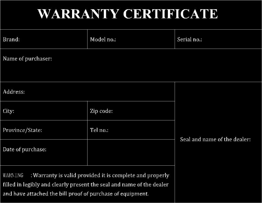
59 59 This Warranty Certificate is unique and not transferrable and may not be reissued. Substitutions of the product, or any product component thereof shall not extend the guarantee. The warranty covers the replacement of all parts that are defective in materials or components used in the manufacturing and/or assembly of the device. The device described in this certificate is guaranteed for a period of ONE YEAR from the date of final sale. The warranty does not cover any faults caused by accident, improper installation and use, improper connection to a power source other than the included or claims due to deterioration in the external appearance of the device due to normal use, nor claims pertaining to the amount of condition of the accessories packaged with the device. Checking the accessories is the responsibility of the purchaser at the time of purchasing the device. The warranty does not cover rechargeable batteries even if they are part of the equipment purchased as they are considered consumables. Any impairment must be reported within a period of fifteen days from the date of purchase. The warranty is voided when any of the following conditions are met: 1. Devices that have been manipulated by another or by anyone other than an authorized service provider. 2. Equipment and accessories in which the serial number has been altered, deleted, filled, or in any way become unreadable. 3. Use of the product other than as intended. To make the use of the warranty, it is necessary to provide the dealer or any authorized service provider the following items: 1. The defective device. 2. Any accessories included with the device. 3. The Warranty Certificate filled out in its entirety. 4. Original invoice/receipt clearly identifying the device and its date of purchase. 5. Description of any faults the device may have. The warranty terms contained in this certificate of guarantee do not exclude, modify, or restrict the statutory rights of the buyer by virtue of the laws in force at the time of purchase, but are added to them. Adapted from the following source:
2
 ATR-22 User Manual 2 Contents Preface... 3 Declaration by Manufacturer... 3 License and Legal Information... 3 Safety Information... 3 Getting Started... 4 Initial Setup... 4 Getting to Know the Device...
DUAL BAND/DUAL DISPLAY RADIO O PERATING M ANUAL - F9V2+
 DUAL BAND/DUAL DISPLAY RADIO O PERATING M ANUAL BF - F9V2+ http://baofengradio.us http://www.baofengradio.us 2 PREFACE Thank you for purchasing the BF-F9V2+ Amateur Portable Radio from Baofeng Radio US,
DUAL BAND/DUAL DISPLAY RADIO OPERATING MANUAL UV-82
 DUAL BAND/DUAL DISPLAY RADIO OPERATING MANUAL UV-82 http://www.baofengradio.us 2 PREFACE Thank you for purchasing the UV-82 Amateur Portable Radio from Baofeng Radio US, the official Baofeng distributor
THANK YOU FOR YOUR PURCHASE OF THE BF-F8HP. THIS DUAL BAND RADIO WILL DELIVER YOU SECURE INSTANT RELIABLE COMMUNICATION.
 Copyright 2014 by BaoFeng Tech All rights reserved. No part of this publication may be reproduced, distributed, or transmitted in any form or by any means, including photocopying, recording, or other electronic
THANK YOU FOR YOUR PURCHASE OF THE UV-82HP. THIS DUAL BAND RADIO WILL DELIVER YOU SECURE INSTANT RELIABLE COMMUNICATION.
 Copyright 2015 by BaoFeng Tech All rights reserved. No part of this publication may be reproduced, distributed, or transmitted in any form or by any means, including photocopying, recording, or other electronic
Battery Informationy/Antenna and Other Accessories Charging the Battery
 Thank You Thank you for your purchase of HYT portable two-way radio. HYT portable radios will provide you with clear and reliable communications in high efficiency. Please read this manual before your
OWNER S MANUAL FM HANDHELD TRANSCEIVER
 , OWNER S MANUAL RPU4200A FM HANDHELD TRANSCEIVER NOTE, OWNER S MANUAL RPU4200A FM HANDHELD TRANSCEIVER We are very grateful for your purchasing brand twoway radios produced by Relm Wireless Corporation.
Reference for UV-5R Menus by Jim Unroe - KC9HI 2-April-2014
 Long Name / Description / / Notes / 0 SQL Carrier Squelch Mutes the speaker of the transceiver in the absence of a strong signal. VHF squelch is either OFF or ON. UHF squelch is either OFF or one of 9
UV-5R Manual. pofung UV-5R
 pofung UV-5R Pre conditions 1 Charge Battery 2 Attach antenna 3 Take Note of: , , , , 4 Orange VFO/MR, BlueA/B, Black BAND, 5 10 Key Number Pad. Used to enter key numbers
User manual AWR-8000 / AWR Advanced Wireless Communications
 User manual AWR-8000 / AWR-8001 Advanced Wireless Communications THANK YOU! Thank you for your purchase of Advanced Wireless Communications AWR-8000 / AWR-8001 two-way radio. This portable two-way radio
Digital Portable Radio
 II TP620 Digital Portable Radio We are very grateful for your purchasing KIRISUN brand two-way radios produced by Kirisun Communications Co., Ltd. We believe KIRISUN two-way radio, which always incorporates
Content. Maintenance. Features ENGLISH. 1 transceiver 1 antenna 1 battery pack 1 belt clip 1 fast desktop charger User manual
 ENGLISH Content 1 transceiver 1 antenna 1 battery pack 1 belt clip 1 fast desktop charger User manual If any items are missing, contact your dealer. Maintenance Your Two Way Radio is an electronic product
THANK YOU FOR YOUR PURCHASE OF THE UV THIS DUAL BAND RADIO WILL DELIVER TO YOU SECURE INSTANT RELIABLE COMMUNICATION.
 Copyright 2016 by BTECH; https://baofengtech.com All rights reserved. No part of this publication may be reproduced, distributed, or transmitted in any form or by any means, including photocopying, recording,
INSTRUCTION MANUAL VHF FM TRANSCEIVER TK-2206 UHF FM TRANSCEIVER TK-3206 B (M,M3 )
") INSTRUCTION MANUAL VHF FM TRANSCEIVER TK-2206 UHF FM TRANSCEIVER TK-3206 B62-1763-00 (M,M3 ) 09 08 07 06 05 04 03 02 01 00 THANK YOU We are grateful you chose KENWOOD for your land mobile radio applications.
INSTRUCTION MANUAL VHF FM TRANSCEIVER TK-2206 UHF FM TRANSCEIVER TK-3206 B62-1763-00 (M,M3 ) 09 08 07 06 05 04 03 02 01 00 THANK YOU We are grateful you chose KENWOOD for your land mobile radio applications.
SET MENU DESCRIPTION:
 COMMAND/KEY DEFINITIONS: [PTT] (PUSH-TO-TALK): Press and hold to transmit; release to receive. SK-SIDE KEY1/[CALL]: - Press the [CALL] button, to activate the FM Radio. Press it again to deactivate the
DUAL BAND MOBILE RADIO USER S MANUAL
 DUAL BAND MOBILE RADIO USER S MANUAL Thank you for your purchase of the product. This dual band radio will deliver to you secure instant reliable communication. Please read this manual carefully before
THANK YOU FOR YOUR PURCHASE OF THE UV THIS DUAL BAND RADIO WILL DELIVER TO YOU SECURE INSTANT RELIABLE COMMUNICATION.
 Copyright 2016 by BTECH; https://baofengtech.com All rights reserved. No part of this publication may be reproduced, distributed, or transmitted in any form or by any means, including photocopying, recording,
INSTRUCTION MANUAL FM HANDHELD TRANSCEIVER
 INSTRUCTION MANUAL PT558 FM HANDHELD TRANSCEIVER NOTE INSTRUCTION MANUAL PT558 FM HANDHELD TRANSCEIVER We are very grateful for your purchasing brand twoway radios produced by Kirisun Electronics (Shenzhen)
RMV25 / RMV50 RMU25 / RMU45
 RMV25 / RMV50 RMU25 / RMU45 Owner's Manual TABLE OF CONTENTS INTRODUCTION... 3 FCC Requirements... 3 SAFETY WARNING INFORMATION... 3 CONTROLS and INDICATORS... 5 FRONT PANEL... 5 LCD Icons and Indicators...
Walkie-Talkie. User Manual and Instruction. Getting Started
 Walkie-Talkie User Manual and Instruction Getting Started Installing the AA Batteries Your radio uses 3 AA Alkaline batteries. 1. With the back of the radio facing you, lift the battery latch up to release
PMR446 Radio Instruction Manual
 Tectalk PRO PMR446 Radio Instruction Manual Thank you for purchasing this radio. All our products are built to offer excellent value by combining advanced features, great design and manufacturing quality.
If any item is missing or have been damaged during the shipment, please notify your MIDLAND dealer.
 Content 1 CT 790 transceiver 1 high gain antenna 1 Li-ion battery pack 1 desktop charger 1 belt clip 1 hand strap If any item is missing or have been damaged during the shipment, please notify your MIDLAND
TLKR T60 OWNER'S MANUAL EN DE FR IT ES PR NL DA NO TU PL SV RU
 TLKR T60 OWNER'S MANUAL EN DE FR IT ES PR NL DA NO TU PL SV RU SF 1 PRODUCT SAFETY AND RF EXPOSURE FOR PORTABLE TWO-WAY RADIOS! Caution ATTENTION! Before using this product, read the RF energy awareness
Pair of PMR446 Two-Way Personal Radios Model: TP391
 Pair of PMR446 Two-Way Personal Radios Model: TP391 USER MANUAL MANUALE D USO MANUEL DE L UTILISATEUR BEDIENUNGSANLEITUNG MANUAL DE USUARIO MANUAL DO USUÁRIO HANDLEIDING BRUKSANVISNING P/N:086L004722-016
SECTION III OPERATION
 SECTION III OPERATION 3.1 INTRODUCTION This section contains information concerning the operation procedures for the BK Radio GPH Flex Mode Series handheld VHF radios. Information on installation and programming
UH45 Series. UHF CB Transceiver. For more exciting new products please visit our website: Australia:
 UH45 Series UHF CB Transceiver For more exciting new products please visit our website: Australia: www.uniden.com.au Controls & Indicators Included in your Package UH45 Series Radio Operating Guide Belt
MobileRadio. Owner'sManual
 EMH MobileRadio Owner'sManual TABLE OF CONTENTS Introduction... 1 Basic Operation... 2 Code Guard Operation... 3 EMH Radio Controls... 4 Button Functions... 4 Built-in Features... 7 Keypad Microphone Operation...
DJ-MD5 PC Software Guidance
 DJ-MD5 PC Software Guidance Ver, 1.00 2018/08/16 1 Appendix I Public... 4 1. Channel... 4 1 Frequency, call type, power... 4 2 Digital Channel Setting... 5 3 Analog Channel Setting... 6 2. Zone... 7 3.
INSTRUCTION MANUAL VHF FM TRANSCEIVER TK-7102H UHF FM TRANSCEIVER TK-8102H KENWOOD CORPORATION B (M)
") INSTRUCTION MANUAL VHF FM TRANSCEIVER TK-7102H UHF FM TRANSCEIVER TK-8102H KENWOOD CORPORATION B62-1596-00 (M) 09 08 07 06 05 04 03 02 01 00 THANK YOU! We are grateful you chose KENWOOD for your personal
INSTRUCTION MANUAL VHF FM TRANSCEIVER TK-7102H UHF FM TRANSCEIVER TK-8102H KENWOOD CORPORATION B62-1596-00 (M) 09 08 07 06 05 04 03 02 01 00 THANK YOU! We are grateful you chose KENWOOD for your personal
1. SAFETY INFORMATION
 1. SAFETY INFORMATION NOTE TO USER Illegal operation is punishable by fine, imprisonment or both. Refer service to Advanced Wireless Communications only. SAFETY It is important that the operator is aware
DC-1122 Compact 5W UHF CB Radio
 DC-1122 Compact 5W UHF CB Radio Instruction Manual Introduction! NOTE Use of the citizen band radio service is licensed in Australia by ACMA Radio communications (Citizen Band Radio Stations) Class Licence
Baofeng UV-5RTips And Hints For Eyes-Free Operation
 Baofeng UV-5RTips And Hints For Eyes-Free Operation Buddy Brannan, KB5ELV, buddy@brannan.name Last Updated: 2 July 2012 Updates And Modifications 2 July 2012: From Jim Unroe, KC9HI: Corrected information
RL /430MHZ DUAL BAND FM TRANSCEIVER OPERATION INSTRUCTION
 RL-502 144/430MHZ DUAL BAND FM TRANSCEIVER OPERATION INSTRUCTION RoHS Table of Contents Packing List...1 Cautions...2 Parts Name & Functions...3 Fitting & Removing the Battery Pack...4 Installation the
XU/XV-100 Series User Manual
 XU/XV-100 Series User Manual This device complies with Part 15 of FCC Rules. Operation is subject to the following two conditions: This device may not cause harmful interference, and 2) This device must
Talkabout T82/ T82 EXTREME OWNER S MANUAL
 Talkabout T82/ T82 EXTREME OWNER S MANUAL B RF ENERGY EXPOSURE AND PRODUCT SAFETY GUIDE FOR PORTABLE TWO-WAY RADIOS ATTENTION! Before using this product, read the RF Energy Exposure and Product Safety
VHF FM TRANSCEIVER/ UHF FM TRANSCEIVER INSTRUCTION MANUAL ÉMETTEUR-RÉCEPTEUR FM VHF/ ÉMETTEUR-RÉCEPTEUR FM UHF MODE D EMPLOI
 TK-2202/ TK-3202 VHF FM TRANSCEIVER/ UHF FM TRANSCEIVER INSTRUCTION MANUAL ÉMETTEUR-RÉCEPTEUR FM VHF/ ÉMETTEUR-RÉCEPTEUR FM UHF MODE D EMPLOI TRANSCEPTOR DE FM VHF/ TRANSCEPTOR DE FM UHF MANUAL DE INSTRUCCIONES
Two-Way Radios. Quick Start Guide. XT460 Display model
 Two-Way Radios Quick Start Guide XT460 Display model CONTENTS Contents..................................... 1 Safety....................................... 2 Batteries and Chargers Safety Information........
SAFETY INFORMATION IMPORTANT FCC LICENSING INFORMATION
 This device complies with part 15 of the FCC Rules. Operation is subject to the following two conditions: (1) This device does not cause harmful interference, and (2) This device must accept any interference
AnyToneTech.com. Package and Product Designed in U.S.A. MADE IN CHINA
 A1.150126 Package and Product Designed in U.S.A. MADE IN CHINA AnyToneTech.com Copyright 2015 by AnyTone Tech All rights reserved. No part of this publication may be reproduced, distributed, or transmitted
UH043SX-2NB. UHF CB Transceiver. For more exciting new products please visit our website: Australia: New Zealand:
 UH043SX-2NB UHF CB Transceiver For more exciting new products please visit our website: Australia: www.uniden.com.au New Zealand: www.uniden.co.nz Controls & Indicators Included in your Package UH043SX-NB
BASIC USER GUIDE BASIC USER GUIDE CONTENTS. GeneralInformation... 2
 GP360 GP360 1 2 7 8 12 3 4 5 9 10 11 13 6 CONTENTS GeneralInformation... 2 Operation and Control Functions..... 2 Radio Controls...................... 2 Audio Signal Tones.................. 3 Programmable
Owner s Manual For Models G-225 & G-227 GMRS/FRS Radio
 Owner s Manual For Models G-225 & G-227 GMRS/FRS Radio FEATURING 22 Channels 38 CTCSS codes VOX Monitor function Call Alert Back-Lit LCD Vibrate Alert (G-227 Only) Scan Roger Beep Tone This device complies
TWO-WAY RADIO. Þ ß Ô ² ú RPV516/RPU416. Owner's Manual
 TM TWO-WAY RADIO Þ ß Ô ² ú RPV516/RPU416 Owner's Manual Thank you! We are grateful that you choose RELM for your land mobile applications. We believe this easyto-use transceiver will provide dependable
OPERATING GUIDE VHF TRANSCEIVER. Iç-G88
 OPERATING GUIDE VHF TRANSCEIVER Iç-G88 INTRODUCTION PREFACE We appreciate you choosing Icom for your communication needs. The MDC 1200 signaling system is built into your IC-G88 vhf transceiver. IMPORTANT
Owner s Manual PMR 446 Handheld transceiver G5
 Owner s Manual PMR 446 Handheld transceiver G5 Featuring 8 Channels 38 CTCSS codes VOX/Babymonitoring Display illumination Scan function Roger Beep Tone Index Accessories 4 Introduction 5 Controls and
ALAN 777 PMR 446 Radio Set User manual
 ALAN 777 PMR 446 Radio Set User manual The all new ALAN 777 represents the very latest and most advanced technology currently available on the PMR446 and LPD market. With its stylish lines and modern design,
Introduction. Included
 CONTENTS Introduction........01 Included.............01 Main Features...........02 Technical Information.......03 Know the Radio..........05 Preparation before using.....06 Basic Functions......11 Function
TX4400 UHF CB RADIO INSTRUCTION MANUAL TX4400 INSTRUCTION MANUAL PAGE 1
 TX4400 UHF CB RADIO INSTRUCTION MANUAL TX4400 INSTRUCTION MANUAL PAGE 1 TABLE OF CONTENTS GENERAL................................... 3 FEATURES.................................. 3 BASIC OPERATION...4 Front
LSC Radio User Guide Information and Guidelines
 LSC Radio User Guide Information and Guidelines The following user guide applies to both the Motorola VL50 and CLS1410 Radio s. Below are guidelines established for usage. 1) Radios and headsets are to
Handheld UHF CB Radio
 Handheld UHF CB Radio Instruction Manual Model: AUHR-014 Customer Helpline 1300 886 649 Welcome Congratulations on choosing to buy an ONIX product. All products brought to you by Onix are manufactured
Operating Guide SMH 1525DT SMU 4525KT Technology Drive West Melbourne, FL RELM Wireless Corporation. All Rights Reserved CC OG 23
 W I R E L E S S C O R P O R AT I O N Operating Guide 7100 Technology Drive West Melbourne, FL 32904 2000 RELM Wireless Corporation. All Rights Reserved CC OG 23 ULUD01083ZZ RELM WIRELESS CORP. 7100 Technology
BCH-270 Owner s Manual
 BCH-270 Owner s Manual By BridgeCom Systems, Inc. TABLE OF CONTENTS CHAPTER 1: INTRODUCTION... 4 WELCOME... 4 SPECIFICATIONS... 4 CHAPTER 2: UNPACKING AND PREPARATION... 5 PARTS LIST... 5 CHARGING THE
TABLE OF CONTENTS. Keypad Programming Manual 1
 TABLE OF CONTENTS How To Program Radios...2 Keypad Programming...2 A. Navigation...3 1. Group Parameters (CH 00)...4 2. Channel Parameters (CH 01 - CH20)...4 3. Global Parameters (GRP 00)...5 B. Group
Commercial Series. CP140 Portable Radio. User Guide
 Commercial Series CP140 Portable Radio User Guide Issue: October 2003 CONTENTS Computer Software Copyrights... 2 Radio Overview..... 3 Operation and Control Functions..... 3 Radio Controls.... 3 LED Indicator.....
AT-D868UV CodePlug Programming Guide
 INTRODUCTION The AnyTone D868UV radio is a VHF and UHF radio with both Digital DMR (Tier I and II) and Analog capabilities. It offers a total of 4,000 channels (Analog and Digital) and up to 130,000 contacts,
GETTING STARTED. Radio layout. LCD display with icons
 GETTING STARTED Radio layout LCD display with icons 1. Key lock button 2. Battery meter 3. Main channel indicator 4. Scan icon 5. Roger beep indicator 6. CTCSS sub-channel indicator 7. VOX indicator 1
BX SERIES HANDHELD RADIOS COMMERCIAL INSTRUCTION MANUAL BX SERIES HANDHELD INSTRUCTION MANUAL PAGE 1. Instruction manual includes models:
 COMMERCIAL BX SERIES HANDHELD RADIOS Instruction manual includes models: BX710 BX720 BX730 INSTRUCTION MANUAL BX SERIES HANDHELD INSTRUCTION MANUAL PAGE 1 WARNING - SAFETY INFORMATION The BX Series are
OPERATING MANUAL Series. FM Portable Radio. Intrinsically-Safe SMARTNET, SmartZone Conventional
 7700 Series OPERATING MANUAL FM Portable Radio Intrinsically-Safe SMARTNET, SmartZone Conventional 1 LAND MOBILE PRODUCT WARRANTY - The manufacturer s warranty statement for this product is available
Owner s Manual Model FR-230 Two Way Family Radio
 Owner s Manual Model FR-230 Two Way Family Radio Family Radio Service Customer Service 1-800-645-4994 Rev NC Released on 4-21-99. Rev A 4/22/99 Changed Phone # to 1-800-645-4994 Rev B 4/27/99 1st production-changed
Instruction Manual. Model: TX-446. Tech Private Mobile Radio (PMR)446MHz
446MHz") Instruction Manual Tech Private Mobile Radio (PMR)446MHz Model: TX-446 TTI TECH CO., LTD. Eundo Bldg, 737-19, Banpo-1dong, Seocho-ku, Seoul, Korea, 137-041 http://www.ttikorea.co.kr TABLE OF CONTENTS 1.
Instruction Manual Tech Private Mobile Radio (PMR)446MHz Model: TX-446 TTI TECH CO., LTD. Eundo Bldg, 737-19, Banpo-1dong, Seocho-ku, Seoul, Korea, 137-041 http://www.ttikorea.co.kr TABLE OF CONTENTS 1.
INSTRUCTION MANUAL MODE D EMPLOI MANUAL DE INSTRUCCIONES MANUALE DI ISTRUZIONI BEDIENUNGSANLEITUNG GEBRUIKSAANWIJZING
 INSTRUCTION MANUAL MODE D EMPLOI MANUAL DE INSTRUCCIONES MANUALE DI ISTRUZIONI BEDIENUNGSANLEITUNG GEBRUIKSAANWIJZING ProTalk TK-320 UHF FM TRANSCEIVER ÉMETTEUR-RÉCEPTEUR FM UHF TRANSCEPTOR DE FM UHF RICETRASMETTITORE
QP350 Digital Two-Way Radio USER MANUAL
 7120350101 QP350 Digital Two-Way Radio USER MANUAL Quantun Electronics, LLC THANK YOU We are grateful for you choice of Quantun production. This Professional Digital two-way radio incorporates the advanced
OWNER S MANUAL
 OWNER S MANUAL 19-1208 RADIOSHACK CORP. FCC ID : AAO1901208 JOB # : 578ZA1 EXHIBIT # : 6 INTRODUCTION Your Radio Shack 19-1208 Business band transceiver is a portable, easy-to-use, two-way radio that you
AWR Advantage & AWR Advantage Plus. User manual. Advanced Wireless Communications
 AWR Advantage & AWR Advantage Plus User manual 0 Advanced Wireless Communications THANK YOU! Thank you for your purchase of Advanced Wireless Communications AWR Advantage/AWR Advantage Plus two-way radio.
DC Instruction Manual. Professional FM Transceiver
 DC-1074 Professional FM Transceiver Instruction Manual Use of the citizen band radio service is licensed in Australia by ACMA Radiocommunications (Citizen Band Radio Stations) Class Licence and in New
Owner s Manual. Model G-223. GMRS/FRS Radio. FEATURES 22 Channels Scan 22 Key Pad Lock Call Alert Power HI/LO Roger Beep Tone
 Owner s Manual Model G-223 GMRS/FRS Radio FEATURES 22 Channels Scan 22 Key Pad Lock Call Alert Power HI/LO Roger Beep Tone This device complies with Part 15 of the FCC rules. Operation is subject to the
T80/T80 EXTREME/T81 HUNTER
 T80/T80 EXTREME/T81 HUNTER OWNER'S MANUAL en pt-pt de-de fr-fr it-it es-es nl-nl da sv fi no-no hu pl ru uk RF ENERGY EXPOSURE AND PRODUCT SAFETY GUIDE FOR PORTABLE TWO- WAY RADIOS ATTENTION! Before using
Instruction Manual. Digital Two-way Radio
 II FP520 Digital Two-way Radio We are very grateful for your purchasing KIRISUN brand two-way radios produced by Kirisun Communications Co., Ltd. We believe KIRISUN two-way radio, which always incorporates
Yaesu FT-25R 2-Meter Handheld Transceiver
 Yaesu FT-25R 2-Meter Handheld Transceiver Reviewed by Dan Wall, W1ZFG ARRL LoTW Administration w1zfg@arrl.org The latest entry into the field of small, inexpensive handhelds is the Yaesu FT-25R. This is
UBZ-LJ8 FM TRANSCEIVER INSTRUCTION MANUAL EMETTEUR-RECEPTEUR FM MODE D EMPLOI RICETRASMETTITORE FM MANUALE DI ISTRUZIONI
 UBZ-LJ8 FM TRANSCEIVER INSTRUCTION MANUAL EMETTEUR-RECEPTEUR FM MODE D EMPLOI TRANSCEPTOR DE FM MANUAL DE INSTRUCCIONES RICETRASMETTITORE FM MANUALE DI ISTRUZIONI FM-HANDFUNKSPRECHGERÄT BEDIENUNGSANLEITUNG
Cat. No OWNER S MANUAL. HTX-212 Two-Meter Mobile Transceiver. Please read before using this transceiver.
 19-1125.fm Page 1 Tuesday, August 3, 1999 9:47 AM Cat. No. 19-1125 OWNER S MANUAL HTX-212 Two-Meter Mobile Transceiver Please read before using this transceiver. 19-1125.fm Page 2 Tuesday, August 3, 1999
INSTRUCTION MANUAL VHF FM TRANSCEIVER TK-2200 UHF FM TRANSCEIVER TK-3200 B (K,K2)
") INSTRUCTION MANUAL VHF FM TRANSCEIVER TK-2200 UHF FM TRANSCEIVER TK-3200 B62-79-00 (K,K2) 09 08 07 06 05 04 03 02 0 00 THANK YOU We are grateful for your purchase of this KENWOOD product and welcome you
INSTRUCTION MANUAL VHF FM TRANSCEIVER TK-2200 UHF FM TRANSCEIVER TK-3200 B62-79-00 (K,K2) 09 08 07 06 05 04 03 02 0 00 THANK YOU We are grateful for your purchase of this KENWOOD product and welcome you
Radio Communications Supply & Installation Specialist. Website
 Radio Communications Supply & Installation Specialist Website www.radiotronics.co.uk Email sales@radiotronics.co.uk Telephone Numbers 0345 0 955 955 02087 190 180 User Guide for: Instructional Icons The
RX1300 MULTIBAND SCANNING RECEIVER INSTRUCTION MANUAL
 RX1300 MULTIBAND SCANNING RECEIVER INSTRUCTION MANUAL CAUTION Please read these instructions carefully before operating your receiver. Your scanner is a complex and powerful unit with many functions. Please
9/14/2017. APX 4000 Portable Radio. Before You Begin. APX 4000: Introduction. Rensselaer County Bureau of Public Safety 800 MHz Radio User Training
 9/14/2017 Rensselaer County Bureau of Public Safety 800 MHz Radio User Training Portable Radio Before You Begin View the Operations Training Presentation first, it covers: Overview of Rensselaer County
Making Life Easier and Safer
 Making Life Easier and Safer Owner s Manual Staying in touch with your family and friends is convenient and easy when using your microtalk radio. Some of the many uses you will discover include: Communicating
1. Antenna 2. Belt Clip 3. Battery compartment with Battery 4. Charger connector 5. Battery compartment cover latch 6. Push to Talk button 7.
 DC-1068 DC-1069 1. Antenna 2. Belt Clip 3. Battery compartment with Battery 4. Charger connector 5. Battery compartment cover latch 6. Push to Talk button 7. Call / Monitor button 8. Speaker Grill 9.
1. Antenna 2. Belt Clip 3. Battery compartment with Battery 4. Charger connector 5. Battery compartment cover latch 6. Push to Talk button 7.
 DC-1068 DC-1069 1. Antenna 2. Belt Clip 3. Battery compartment with Battery 4. Charger connector 5. Battery compartment cover latch 6. Push to Talk button 7. Call / Monitor button 8. Speaker Grill 9. LCD
Operating Instructions DBH03R - 80 Channel 0.5 watt UHF Hand held CB radios with rechargeable batteries & USB charge cable.
 Operating Instructions DBH03R - 80 Channel 0.5 watt UHF Hand held CB radios with rechargeable batteries & USB charge cable. DBH03RTC - 80 Channel 0.5 watt UHF Hand held CB radios with rechargeable batteries,
G11 I N S T R U C T I O N G U I D E. Midland PMR446 Transceiver
 PMR446 Transceiver G11 I N S T R U C T I O N G U I D E Midland PMR446 Transceiver MIDLAND G11 PMR446 Transceiver Thanks for choosing Midland! G11 is a portable transceiver that is free use in almost all
TWO-WAY RADIO MODEL CXR925
 Making Life Easier and Safer Owner s Manual Staying in touch with your family and friends is convenient and easy when using your microtalk radio. Some of the many uses you will discover include: Communicating
KENWOOD SKY COMMAND SYSTEM
 KENWOOD SKY COMMAND SYSTEM Operation Manual KENWOOD COMMINICATIONS CORPORATION KENWOOD COMMUNICATIONS CORPORATION This operation manual is used for the KENWOOD SKY COMMAND SYSTEM (hereinafter referred
INSTRUCTION MANUAL VHF FM TRANSCEIVER TK-6110 B (K,K2)
") INSTRUCTION MANUAL VHF FM TRANSCEIVER TK-6110 B62-1216-20 (K,K2) 09 08 07 06 05 04 03 02 THANK YOU! We are grateful you chose KENWOOD for your land mobile applications. We believe this easy-to-use transceiver
INSTRUCTION MANUAL VHF FM TRANSCEIVER TK-6110 B62-1216-20 (K,K2) 09 08 07 06 05 04 03 02 THANK YOU! We are grateful you chose KENWOOD for your land mobile applications. We believe this easy-to-use transceiver
NAUTICO1 (NT1) Owner s Guide
 Owner s Guide") N NAUTICO1 (NT1) Owner s Guide www.midlandradio.com TABLE OF CONTENTS. 1 Introduction.. 2 Important Notice, FCC Licensing... 3 LCD Display.. 4 Controls. 5 Battery Installation. 6 Installing the Belt Clip
N NAUTICO1 (NT1) Owner s Guide www.midlandradio.com TABLE OF CONTENTS. 1 Introduction.. 2 Important Notice, FCC Licensing... 3 LCD Display.. 4 Controls. 5 Battery Installation. 6 Installing the Belt Clip
MXT100. GMRS Radio OWNER S MANUAL. midlandusa.com
 MXT100 GMRS Radio OWNER S MANUAL Welcome to the World of Midland electronics Congratulations on your purchase of a high quality MIDLAND product. Your 2-way radio represents state-of-the-art high-tech engineering.
TX670 POCKET SIZE UHF CB RADIO INSTRUCTION MANUAL 2 WATT HANDHELD. TX670 Instruction Manual Page 1
 TX670 POCKET SIZE 2 WATT HANDHELD UHF CB RADIO INSTRUCTION MANUAL TX670 Instruction Manual Page 1 Warning: Safety Information The TX670 is a radio frequency transmitting device. When transmitting, keep
Model: TP380 User Manual
 Model: TP380 User Manual 1 UHF RADIO TRANSCEIVER MODEL: TP380 USER MANUAL INTRODUCTION Thank you for selecting the Oregon Scientific TP380 as your product of choice. This product is a portable, easy-to-use
Sporty s Air Scan. Operator s Manual Sportsman s Market, Inc.
 Sporty s Air Scan Operator s Manual 2017 Sportsman s Market, Inc. Simplified Directions. 1. Turn the unit on (push and hold red power button for 2 seconds). 2. Select AIR (Aviation), AUX (wired auxiliary
Montgomery County Emergency Services 800 MHz Rebanding Training. MTS 2000 Type II & III. Portable Radio
 Montgomery County Emergency Services 800 MHz Rebanding Training Portable Radio Before You Begin View the main training video first, it covers: General Radio Review Overview of Montgomery County s Radio
AUDIOVOX GMRS4WM Owner s/installation Manual
 AUDIOVOX GMRS4WM Owner s/installation Manual GMRS (General Mobile Radio Service) Wall Mount Charger Patent Pending www.asaelectronics.com WARNING Replacement or substitution of transistors, diodes, or
GP344R User Guide B98-B. English
 M GP344R User Guide 6864110B98-B M COMPUTER SOFTWARE COPYRIGHTS COMPUTER SOFTWARE COPYRIGHTS The Motorola products described in this manual may include copyrighted Motorola computer programs stored in
TX3420 REMOTE MOUNT UHF RADIO
 TX3420 REMOTE MOUNT UHF RADIO Introduction........................... 2 Important information concerning uhf cb radio................. 2 Emergency channels.................... 3 telemetry channels.....................
PROFESSIONAL DIGITAL TWO-WAY RADIO SYSTEM MOTOTRBO DGP SERIES CONNECT PLUS NON-DISPLAY PORTABLE USER GUIDE
 PROFESSIONAL DIGITAL TWO-WAY RADIO SYSTEM MOTOTRBO DGP SERIES CONNECT PLUS NON-DISPLAY PORTABLE USER GUIDE Declaration of Conformity DECLARATION OF CONFORMITY Per FCC CFR 47 Part 2 Section 2.1077(a) Responsible
X-TRA TALK. GXT500/550 Series GMRS/FRS Radio OWNER'S MANUAL.
 X-TRA TALK GXT500/550 Series GMRS/FRS Radio OWNER'S MANUAL TABLE OF CONTENTS 2 Introduction 3 Important Notice, FCC Licensing 4 LCD Display 5 Controls 5 Battery Installation 6 Installing the Belt Clip
TLKR T92 H2O OWNER'S MANUAL. it-it. nl-nl. fi-fi. pt-pt. nb-no tr-tr pl-pl ru-ru uk-ua
 TLKR T92 H2O OWNER'S MANUAL en de-de fr-fr it-it es-es pt-pt nl-nl da-dk sv-se fi-fi nb-no tr-tr pl-pl ru-ru uk-ua RF ENERGY EXPOSURE AND PRODUCT SAFETY GUIDE FOR PORTABLE TWO- WAY RADIOS ATTENTION! Before
RELM Wireless Corporation
 RELM Wireless Corporation 1 THANK YOU Thank you for your purchase of the RELM two-way portable radio. This easy-to-use radio adopts the latest advanced technology, providing reliable communication performance
2 watt handheld UHF CB radio I N S T R U C T I O N M A N U A L
 2 watt handheld UHF CB radio I N S T R U C T I O N M A N U A L CONTENTS IMPORTANT INFORMATION...3 Possible Issues...3 TELEMETRY CHANNELS...3 FEATURES...4 RADIO CONTROLS...4 LCD Display...5 POWERING THE
Headset Intercom System. Operating Instructions
 Headset Intercom System Model C1025 Operating Instructions Headset and Transceiver Pack Base Station Model C1025 Table of Contents Intended Use...iii FCC Information...iii Service...iii System Descriptions...1
SMH250D/SMU250K User s Guide
 SMH250D/SMU250K User s Guide WIRELESS CORPORATION 7100 Technology Drive West Melbourne, FL 32904 2000 RELM Wireless Corporation. All Rights Reserved ULZZ01101ZZ RELM WIRELESS CORPORATION 7100 Technology
Function Key Settings THE TAIT ORCA 5000 CORPORATE HEAD OFFICE NEW ZEALAND. Tait Electronics Ltd CANADA. P O Box 1645, Christchurch
 Custom Settings 5015 CONVENTIONAL TAIT ORCA Function Key Settings Short Press Long Press THE TAIT ORCA 5000 F1: CORPORATE HEAD OFFICE SERIES OF F2: Ext1: Ext2: Handset Mode Volume Keys Volume Up: Volume