EE301 Electronics I , Fall
|
|
|
- Margery Wilkinson
- 5 years ago
- Views:
Transcription


1 EE301 Electronics I , Fall
 Semiconductor materials and their properties, Covalent Bond Model, Drift currents and Mobility, Impurities in Semiconductors, Electron and Hole Concentrations In Doped Semiconductor, Mobility and")
2 1. Introduction to Microelectronics (1 Week/3 Hrs.) Introduction, Historical Background, Basic Consepts 2. Rewiev of Semiconductors (1 Week/3 Hrs.) Semiconductor materials and their properties, Covalent Bond Model, Drift currents and Mobility, Impurities in Semiconductors, Electron and Hole Concentrations In Doped Semiconductor, Mobility and Resistivity in Doped Semiconductors, Diffusion Currents, Energy Band Model 3. Diodes & Applications of Diodes (2 Weeks/6 Hrs.) The Ideal Diode, pn junction as a Diode, Large-Signal and Small-Signal Operation, the i v Characteristics of the Diode, Applications of Diodes: Half-wave And Full- Wave Rectifier Circuits, Voltage Regulation, Limiting Circuits, Voltage Doublers, Diodes as Level Shifters.. 4. Bipolar Junction Transistors (BJTs) & BJT Amplifiers (3 Weeks/9 Hrs.) Physical Structure of The BJTs, Operation of BJTs in Active Mode, BJT Models and Characteristics, Large-Signal Model, the i v Characteristics, Concept of Transconductance, Small-Signal Model, Early Effect, Operation of BJTs in Saturation Mode, NPN and PNP Transistors. General Considerations for BJT Amplifiers, Biasing. 5. MOSs & CMOS Amplifiers (3 Weeks/9 Hrs.) Structure of MOSFET, Operation of MOSFET, Qualitative Analysis, Derivation of I-V Characteristics, Channel-Length Modulation, Large-Signal Model, Small-Signal Model 6. Operational Amplifiers (Op-Amps) (2 Weeks/6 Hrs.) General Considerations, Op-Amp-Based Circuits, Noninverting Amplifier, Inverting Amplifier, Integrator and Differentiator, Voltage Adder, Nonlinear Functions, Precision Rectifier. 7. Cascaded Stages & Current Mirrors (2 Weeks/6 Hrs.) Cascaded Stages, Cascade as a Current Source, Cascade as an Amplifier, Current Mirrors, Initial Thoughts, Bipolar Current Mirror, MOS Current Mirror.


3 The bipolar transistor was invented in 1945 by Shockley, Brattain, and Bardeen at Bell Laboratories, subsequently replacing vacuum tubes in electronic systems and paving the way for integrated circuits.
4 In this chapter, we analyze the structure and operation of bipolar transistors, preparing ourselves for the study of circuits employing such devices. Following, we aim to understand the physics of the transistor, derive equations that represent its I/V characteristics, and develop an equivalent model that can be used in circuit analysis and design. The outline below illustrates the sequence of concepts introduced in this chapter.

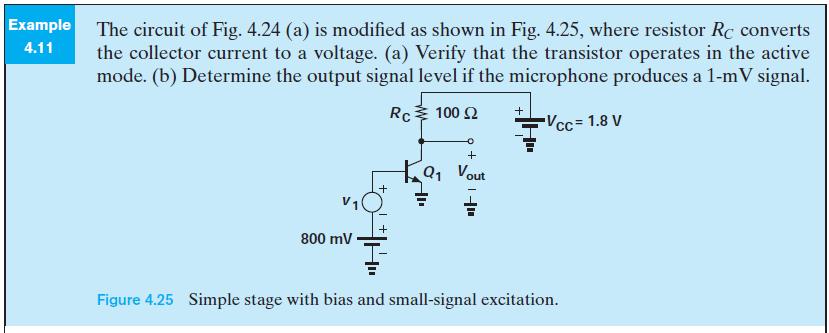
5 In its simplest form, the bipolar transistor can be viewed as a voltage-dependent current source. The amplification factor or voltage gain of the circuit, A V, is defined as;
6 The foregoing study reveals that a voltage-controlled current source can indeed provide signal amplification. Bipolar transistors are an example of such current sources and can ideally be modeled as shown in figure below. Note that the device contains three terminals and its output current is an exponential function of V 1. As three-terminal devices, bipolar transistors make the analysis of circuits more difficult. With three-terminal elements, one may consider the current and voltage between every two terminals, arriving at a complex set of equations. Fortunately, as we develop our understanding of the transistor s operation, we discard some of these current and voltage combinations as irrelevant, thus obtaining a relatively simple model.
7 Structure of BJT s The bipolar transistor consists of three doped regions forming a sandwich. Shown in figure below is an example comprising of a p layer sandwiched between two n regions and called an npn transistor. The three terminals are called the base, the emitter, and the collector. As explained later, the emitter emits charge carriers and the collector collects them while the base controls the number of carriers that make this journey. We readily note from the figures that the device contains two pn junction diodes: one between the base and the emitter and another between the base and the collector. While this simple diagram may suggest that the device is symmetric with respect to the emitter and the collector, in reality, the dimensions and doping levels of these two regions are quite different.
8 Structure of BJT s Before continuing with the bipolar transistor, it is instructive to study an interesting effect in pn junctions. Consider the reverse-biased junction depicted in fig. below and the depletion region sustains a strong electric field. Now suppose an electron is somehow injected from outside into the right side of the depletion region. What happens to this electron? Serving as a minority carrier on the p side, the electron experiences the electric field and is rapidly swept away into the n side. The ability of a reverse-biased pn junction to efficiently collect externally-injected electrons proves essential to the operation of the bipolar transistor.
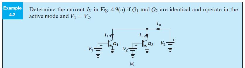
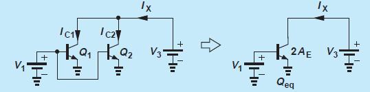
9 Operation Of BJT In Active Mode In this section, we analyze the operation of the transistor, aiming to prove that, under certain conditions, it indeed acts as a voltage-controlled current source. More specifically, we intend to show that (a) the current flow from the emitter to the collector can be viewed as a current source tied between these two terminals, and (b) this current is controlled by the voltage difference between the base and the emitter, V BE. We begin our study with the assumption that the base-emitter junction is forwardbiased (V BE > 0) and the base-collector junction is reverse-biased (V BC < 0). Under these conditions, we say the device is biased in the forward active region or simply in the active mode.
10 Operation Of BJT In Active Mode To understand why the transistor cannot be modeled as merely two back-to-back diodes, we must examine the flow of charge inside the device, bearing in mind that the base region is very thin. Since the base-emitter junction is forward-biased, electrons flow from the emitter to the base and holes from the base to the emitter. For proper transistor operation, the former current component must be much greater than the latter, requiring that the emitter doping level be much greater than that of the base. Thus, we denote the emitter region with n+, where the superscript emphasizes the high doping level. Figure below summarizes these observations thus far. What happens to electrons as they enter the base? Since the base region is thin, most of the electrons reach the edge of the collector-base depletion region, beginning to experience the built-in electric field. Consequently, the electrons are swept into the collector region and absorbed by the positive battery terminal. We therefore observe that the reversebiased collector-base junction carries a current because minority carriers are injected into its depletion region.
11 Operation Of BJT In Active Mode Let us summarize our thoughts. In the active mode, an npn bipolar transistor carries a large number of electrons from the emitter, through the base, to the collector while drawing a small current of holes through the base terminal. We must now answer several questions. (a) First, how do electrons travel through the base: by drift or diffusion? (b) Second, how does the resulting current depend on the terminal voltages? (c) Third, how large is the base current? Collector Current
12 Collector Current Equation above implies that the bipolar transistor indeed operates as a voltagecontrolled current source, proving a good candidate for amplification. We may alternatively say the transistor performs voltage-to-current conversion.
13
14
15
16 Collector Current Equation above reveals an interesting property of the bipolar transistor: The collector current does not depend on the collector voltage (so long as the device remains in the active mode). Thus, for a fixed base-emitter voltage, the device draws a constant current, acting as a current source. Plotted in Fig. below is the current as a function of the collector-emitter voltage, exhibiting a constant value for V CE > V 1. Constant current sources find application in many electronic circuits and numerous examples of their usage can be found in literature.

17 Base and Emitter Currents Having determined the collector current, we now turn our attention to the base and emitter currents and their dependence on the terminal voltages. Since the bipolar transistor must satisfy Kirchoff s current law, calculation of the base current readily yields the emitter current as well. In the npn transistor, the base current, B I, results from the flow of holes. The hole and electron currents in a forwardbiased pn junction bear a constant ratio given by the doping levels and other parameters. Thus, the number of holes entering from the base to the emitter is a constant fraction of the number of electrons traveling from the emitter to the base. As an example, for every 200 electrons injected by the emitter, one hole must be supplied by the base. As a result, the base current must supply holes for both reverse injection into the emitter and recombination with the electrons traveling toward the collector. We can therefore view I B as a constant fraction of I E or a constant fraction of I C. It is common to write
18 Base and Emitter Currents where β is called the current gain of the transistor because it shows how much the base current is amplified. Depending on the device structure, the β of npn transistors typically ranges from 50 to 200. In order to determine the emitter current, we apply the KCL to the transistor with the current directions depicted in previous figure:
19 Large Signal Model Since the base-emitter junction is forward-biased in the active mode, we can place a diode between the base and emitter terminals. Moreover, since the current drawn from the collector and flowing into the emitter depends on only the base-emitter voltage, we add a voltage-controlled current source between the collector and the emitter. Why the equivalent circuit above is called the large-signal model. This terminology emphasizes that the model can be used for arbitrarily large voltage and current changes in the transistor (so long as the device operates in the active mode). For example, if the base-emitter voltage varies from 800 mv to 300 mv, and hence the collector current by many orders of magnitude.

20 Large Signal Model
21 Large Signal Model
22 Large Signal Model (I-V Characteristics) The first characteristic to study is, of course, the exponential relationship inherent in the device. Figure below plots I C versus V BE with the assumption that the collector voltage is constant and no lower than the base voltage. I C is independent of V CE ; thus, different values of V CE do not alter the characteristic. Next, lets examine I C for a given V BE but with V CE varying. The characteristic is a horizontal line because I C is constant if the device remains in the active mode (V CE > V BE ). On the other hand, if different values are chosen for V BE, the characteristic moves up or down.
23
24 Transconductance Our study thus far shows that the bipolar transistor acts as a voltage-dependent current source (when operating in the forward active region). An important question that arises here is, how is the performance of such a device quantified? In other words, what is the measure of the goodness of a voltage-dependent current source? The example depicted in Fig. 4.1 suggests that the device becomes stronger as K increases because a given input voltage yields a larger output current. We must therefore concentrate on the voltage-to-current conversion property of the transistor, particularly as it relates to amplification of signals. More specifically, we ask, if a signal changes the base-emitter voltage of a transistor by a small amount, how much change is produced in the collector current? Denoting the change in I C by I C, we recognize that the strength of the device can be represented by I C /V BE. For example, if a base-emitter voltage change of 1 mv results in a I C of 0.1mA in one transistor and 0.5mA in another, we can view the latter as a better voltage-dependent current source or voltage-to-current converter.
25 Transconductance Note that this definition applies to any device that approximates a voltage-dependent current source (e.g., another type of transistor). For a bipolar transistor,
26 Small Signal Model Electronic circuits, e.g., amplifiers, may incorporate a large number of transistors, thus posing great difficulties in the analysis and design. Recall from Chapter 3 that diodes can be reduced to linear devices through the use of the small-signal model. A similar benefit occures if a small-signal model can be developed for transistors. The derivation of the small-signal model from the large-signal counterpart is relatively straightforward. We perturb the voltage difference between every two terminals (while the third terminal remains at a constant potential), determine the changes in the currents flowing through all terminals, and represent the results by proper circuit elements such as controlled current sources or resistors. Figure depicts two conceptual examples where V BE or V CE is changed by V and the changes in I C, I B, and I E are examined.
27 Small Signal Model Let us begin with a change in V BE while the collector voltage is constant. We know from the definition of transconductance that The simple small-signal model developed here serves as a powerful, versatile tool in the analysis and design of bipolar circuits. We should remark that both parameters of the model, g m and r π, depend on the bias current of the device. With a high collector bias current, a greater g m is obtained, but the impedance between the base and emitter falls to lower values.
28 Small Signal Model How about a change in the collector-emitter voltage? Such a change also results in a zero change in the terminal currents.

29 Small Signal Model
30 Small Signal Model

31 Small Signal Model
32 Early Effect
33 Early Effect
34 Early Effect (Large-Signal and Small-Signal Models) The presence of Early effect alters the transistor models developed in previous Sections. The large-signal model must now bemodified to that in figüre below, where For the small-signal model, we note that the controlled current source remains unchanged and g M is expressed as
35 Early Effect (Large-Signal and Small-Signal Models) Considering that the collector current does vary with V CE, let us now apply a voltage change at the collector and measure the resulting current change; Since the voltage and current change correspond to the same two terminals, they satisfy Ohm s Law, yielding an equivalent resistor: The small-signal model contains only one extra element, r O, to represent the Early effect. Called the output resistance, r O plays a critical role in high-gain amplifiers. Note that both r π and r O are inversely proportionally to the bias current, I C.
36 Early Effect (Large-Signal and Small-Signal Models)
37 Summary
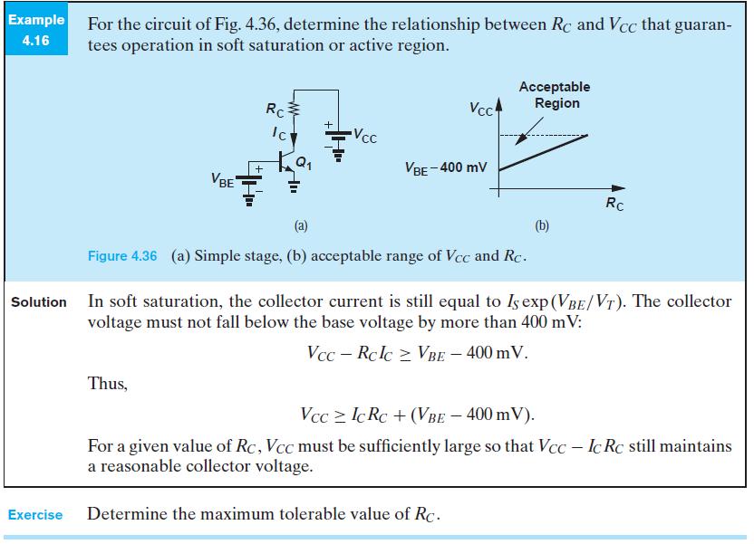
38 Saturation Mode As mentioned in the previous section, it is desirable to operate bipolar devices in the forward active region, where they act as voltage-controlled current sources. In this section, we study the behavior of the device outside this region and the resulting difficulties. What happens if V CE < V BE, i.e., V BC > 0 and the B-C junction is forward biased? We say the transistor enters the saturation region. Even in this case the transistor continues to operate as in the active mode, and we say the device is in soft saturation. (If V BC is about zero, small collector current) If the collector voltage drops further, the B-C junction experiences greater forward bias, carrying a significant current. Consequently, a large number of holes must be supplied to the base terminal as if β is reduced. In other words, heavy saturation leads to a sharp rise in the base current and hence a rapid fall in β.
39 Saturation Mode
40 Saturation Mode In addition to a drop in β, the speed of bipolar transistors also degrades in saturation. Thus, electronic circuits rarely allow operation of bipolar devices in this mode. As a rule of thumb, we permit soft saturation with V BC < 400mV because the current in the B-C junction is negligible, provided that various tolerances in the component values do not drive the device into deep saturation. It is important to recognize that the transistor simply draws a current from any component tied to its collector, e.g., a resistor. Thus, it is the external component that defines the collector voltage and hence the region of operation. In the deep saturation region, the collector-emitter voltage approaches a constant value called V CE,sat (about 200 mv). Under this condition, the transistor bears no resemblance to a controlled current source and can be modeled as shown in Fig. below
41 Saturation Mode
42 Pnp Transistor Similar analysis can be achieved for pnp transistor as npn one.!!!!!!!!
43 END OF CHAPTER 4, Part 1 Dr. Yılmaz KALKAN
EE301 Electronics I , Fall
 EE301 Electronics I 2018-2019, Fall 1. Introduction to Microelectronics (1 Week/3 Hrs.) Introduction, Historical Background, Basic Consepts 2. Rewiev of Semiconductors (1 Week/3 Hrs.) Semiconductor materials
ECE 310 Microelectronics Circuits
 ECE 310 Microelectronics Circuits Bipolar Transistors Dr. Vishal Saxena (vishalsaxena@boisetstate.edu) Jan 20, 2014 Vishal Saxena 1 Bipolar Transistor n the chapter, we will study the physics of bipolar
EE301 Electronics I , Fall
 EE301 Electronics I 2018-2019, Fall 1. Introduction to Microelectronics (1 Week/3 Hrs.) Introduction, Historical Background, Basic Consepts 2. Rewiev of Semiconductors (1 Week/3 Hrs.) Semiconductor materials
Chapter 3. Bipolar Junction Transistors
 Chapter 3. Bipolar Junction Transistors Outline: Fundamental of Transistor Common-Base Configuration Common-Emitter Configuration Common-Collector Configuration Introduction The transistor is a three-layer
Physics of Bipolar Transistor
 Physics of Bipolar Transistor Motivations - In many electronic applications, amplifier is the most fundamental building block. Ex Audio amplifier: amplifies electric signal to drive a speaker RF Power
Chapter Two "Bipolar Transistor Circuits"
 Chapter Two "Bipolar Transistor Circuits" 1.TRANSISTOR CONSTRUCTION:- The transistor is a three-layer semiconductor device consisting of either two n- and one p-type layers of material or two p- and one
BJT. Bipolar Junction Transistor BJT BJT 11/6/2018. Dr. Satish Chandra, Assistant Professor, P P N College, Kanpur 1
 BJT Bipolar Junction Transistor Satish Chandra Assistant Professor Department of Physics P P N College, Kanpur www.satish0402.weebly.com The Bipolar Junction Transistor is a semiconductor device which
Chapter 3 Bipolar Junction Transistors (BJT)
") Chapter 3 Bipolar Junction Transistors (BJT) Transistors In analog circuits, transistors are used in amplifiers and linear regulated power supplies. In digital circuits they function as electrical switches,
Chapter 3 Bipolar Junction Transistors (BJT) Transistors In analog circuits, transistors are used in amplifiers and linear regulated power supplies. In digital circuits they function as electrical switches,
Basic Electronics Prof. Dr. Chitralekha Mahanta Department of Electronics and Communication Engineering Indian Institute of Technology, Guwahati
 Basic Electronics Prof. Dr. Chitralekha Mahanta Department of Electronics and Communication Engineering Indian Institute of Technology, Guwahati Module: 2 Bipolar Junction Transistors Lecture-1 Transistor
Bipolar Junction Transistors (BJTs) Overview
 Overview") 1 Bipolar Junction Transistors (BJTs) Asst. Prof. MONTREE SIRIPRUCHYANUN, D. Eng. Dept. of Teacher Training in Electrical Engineering, Faculty of Technical Education King Mongkut s Institute of Technology
1 Bipolar Junction Transistors (BJTs) Asst. Prof. MONTREE SIRIPRUCHYANUN, D. Eng. Dept. of Teacher Training in Electrical Engineering, Faculty of Technical Education King Mongkut s Institute of Technology
Student Lecture by: Giangiacomo Groppi Joel Cassell Pierre Berthelot September 28 th 2004
 Student Lecture by: Giangiacomo Groppi Joel Cassell Pierre Berthelot September 28 th 2004 Lecture outline Historical introduction Semiconductor devices overview Bipolar Junction Transistor (BJT) Field
Lecture 4. Reading: Chapter EE105 Fall 2007 Lecture 4, Slide 1 Prof. Liu, UC Berkeley
 Lecture 4 OUTLNE Bipolar Junction Transistor (BJT) General considerations Structure Operation in active mode Large-signal model and - characteristics Reading: Chapter 4.1-4.4.2 EE105 Fall 2007 Lecture
Analog & Digital Electronics Course No: PH-218
 Analog & Digital Electronics Course No: PH-218 Lec-5: Bipolar Junction Transistor (BJT) Course nstructors: Dr. A. P. VAJPEY Department of Physics, ndian nstitute of Technology Guwahati, ndia 1 Bipolar
UNIT 3: FIELD EFFECT TRANSISTORS
 FIELD EFFECT TRANSISTOR: UNIT 3: FIELD EFFECT TRANSISTORS The field effect transistor is a semiconductor device, which depends for its operation on the control of current by an electric field. There are
Review Energy Bands Carrier Density & Mobility Carrier Transport Generation and Recombination
 Review Energy Bands Carrier Density & Mobility Carrier Transport Generation and Recombination Current Transport: Diffusion, Thermionic Emission & Tunneling For Diffusion current, the depletion layer is
Microelectronic Circuits, Kyung Hee Univ. Spring, Bipolar Junction Transistors
 Bipolar Junction Transistors 1 Introduction physical structure of the bipolar transistor and how it works How the voltage between two terminals of the transistor controls the current that flows through
Chapter 4 Physics of Bipolar Transistors. EE105 - Spring 2007 Microelectronic Devices and Circuits. Structure and Symbol of Bipolar Transistor
 EE105 - Spring 2007 Microelectronic Devices and ircuits Lecture 10 Bipolar ransistors hapter 4 Physics of Bipolar ransistors 4.1 General onsiderations 4.2 Structure of Bipolar ransistor 4.3 Operation of
ECE 440 Lecture 29 : Introduction to the BJT-I Class Outline:
 ECE 440 Lecture 29 : Introduction to the BJT-I Class Outline: Narrow-Base Diode BJT Fundamentals BJT Amplification Things you should know when you leave Key Questions How does the narrow-base diode multiply
Electronics I - Physics of Bipolar Transistors
 Chapter 5 Electronics I - Physics of Bipolar Transistors B E N+ P N- C B E C Fall 2017 claudio talarico 1 source: Sedra & Smith Thin Base Types of Bipolar Transistors n+ p n- Figure - A simplified structure
Bipolar Junction Transistors
 Bipolar Junction Transistors Invented in 1948 at Bell Telephone laboratories Bipolar junction transistor (BJT) - one of the major three terminal devices Three terminal devices more useful than two terminal
Chapter 8. Field Effect Transistor
 Chapter 8. Field Effect Transistor Field Effect Transistor: The field effect transistor is a semiconductor device, which depends for its operation on the control of current by an electric field. There
ET215 Devices I Unit 4A
 ITT Technical Institute ET215 Devices I Unit 4A Chapter 3, Section 3.1-3.2 This unit is divided into two parts; Unit 4A and Unit 4B Chapter 3 Section 3.1 Structure of Bipolar Junction Transistors The basic
Lesson 5. Electronics: Semiconductors Doping p-n Junction Diode Half Wave and Full Wave Rectification Introduction to Transistors-
 Lesson 5 Electronics: Semiconductors Doping p-n Junction Diode Half Wave and Full Wave Rectification Introduction to Transistors- Types and Connections Semiconductors Semiconductors If there are many free
Module 2. B.Sc. I Electronics. Developed by: Mrs. Neha S. Joshi Asst. Professor Department of Electronics Willingdon College, Sangli
 Module 2 B.Sc. I Electronics Developed by: Mrs. Neha S. Joshi Asst. Professor Department of Electronics Willingdon College, Sangli BIPOLAR JUNCTION TRANSISTOR SCOPE OF THE CHAPTER- This chapter introduces
Lecture 3: Transistors
 Lecture 3: Transistors Now that we know about diodes, let s put two of them together, as follows: collector base emitter n p n moderately doped lightly doped, and very thin heavily doped At first glance,
Power Bipolar Junction Transistors (BJTs)
") ECE442 Power Semiconductor Devices and Integrated Circuits Power Bipolar Junction Transistors (BJTs) Zheng Yang (ERF 3017, email: yangzhen@uic.edu) Power Bipolar Junction Transistor (BJT) Background The
ECE442 Power Semiconductor Devices and Integrated Circuits Power Bipolar Junction Transistors (BJTs) Zheng Yang (ERF 3017, email: yangzhen@uic.edu) Power Bipolar Junction Transistor (BJT) Background The
KOM2751 Analog Electronics :: Dr. Muharrem Mercimek :: YTU - Control and Automation Dept. 1 2 (CONT D - II) DIODE APPLICATIONS
 DIODE APPLICATIONS") KOM2751 Analog Electronics :: Dr. Muharrem Mercimek :: YTU - Control and Automation Dept. 1 2 (CONT D - II) DIODE APPLICATIONS Most of the content is from the textbook: Electronic devices and circuit theory,
KOM2751 Analog Electronics :: Dr. Muharrem Mercimek :: YTU - Control and Automation Dept. 1 2 (CONT D - II) DIODE APPLICATIONS Most of the content is from the textbook: Electronic devices and circuit theory,
FIELD EFFECT TRANSISTOR (FET) 1. JUNCTION FIELD EFFECT TRANSISTOR (JFET)
 1. JUNCTION FIELD EFFECT TRANSISTOR (JFET)") FIELD EFFECT TRANSISTOR (FET) The field-effect transistor (FET) is a three-terminal device used for a variety of applications that match, to a large extent, those of the BJT transistor. Although there
FIELD EFFECT TRANSISTOR (FET) The field-effect transistor (FET) is a three-terminal device used for a variety of applications that match, to a large extent, those of the BJT transistor. Although there
EIE209 Basic Electronics. Transistor Devices. Contents BJT and FET Characteristics Operations. Prof. C.K. Tse: T ransistor devices
 EIE209 Basic Electronics Transistor Devices Contents BJT and FET Characteristics Operations 1 What is a transistor? Three-terminal device whose voltage-current relationship is controlled by a third voltage
UNIT 3 Transistors JFET
 UNIT 3 Transistors JFET Mosfet Definition of BJT A bipolar junction transistor is a three terminal semiconductor device consisting of two p-n junctions which is able to amplify or magnify a signal. It
Lecture 24: Bipolar Junction Transistors (1) Bipolar Junction Structure, Operating Regions, Biasing
 Bipolar Junction Structure, Operating Regions, Biasing") Lecture 24: Bipolar Junction Transistors (1) Bipolar Junction Structure, Operating Regions, Biasing BJT Structure the BJT is formed by doping three semiconductor regions (emitter, base, and collector)
Lecture 24: Bipolar Junction Transistors (1) Bipolar Junction Structure, Operating Regions, Biasing BJT Structure the BJT is formed by doping three semiconductor regions (emitter, base, and collector)
Introduction to semiconductor technology
 Introduction to semiconductor technology Outline 7 Field effect transistors MOS transistor current equation" MOS transistor channel mobility Substrate bias effect 7 Bipolar transistors Introduction Minority
COE/EE152: Basic Electronics. Lecture 5. Andrew Selasi Agbemenu. Outline
 COE/EE152: Basic Electronics Lecture 5 Andrew Selasi Agbemenu 1 Outline Physical Structure of BJT Two Diode Analogy Modes of Operation Forward Active Mode of BJTs BJT Configurations Early Effect Large
Bipolar junction transistors.
 Bipolar junction transistors. Third Semester Course code : 15EECC202 Analog electronic circuits (AEC) Team: Dr. Nalini C Iyer, R.V. Hangal, Sujata N, Prashant A, Sneha Meti AEC Team, Faculty, School of
fiziks Institute for NET/JRF, GATE, IIT-JAM, M.Sc. Entrance, JEST, TIFR and GRE in Physics
 nstitute for NT/JF, GAT, T-JAM, M.Sc. ntrance, JST, TF and G in Physics 3. ipolar Junction Transistors 3.1 Transistor onstruction Transistor is a three-layer semiconductor device consisting of either two
Improving Amplifier Voltage Gain
 15.1 Multistage ac-coupled Amplifiers 1077 TABLE 15.3 Three-Stage Amplifier Summary HAND ANALYSIS SPICE RESULTS Voltage gain 998 1010 Input signal range 92.7 V Input resistance 1 M 1M Output resistance
PHYS 3050 Electronics I
 PHYS 3050 Electronics I Chapter 4. Semiconductor Diodes and Transistors Earth, Moon, Mars, and Beyond Dr. Jinjun Shan, Associate Professor of Space Engineering Department of Earth and Space Science and
Bipolar Junction Transistors (BJTs)
") C H A P T E R 6 Bipolar Junction Transistors (BJTs) Figure 6.1 A simplified structure of the npn transistor and pnp transistor. Table 6.1: BJT modes of Operation Mode Cutoff Active Saturation EBJ Reverse
C H A P T E R 6 Bipolar Junction Transistors (BJTs) Figure 6.1 A simplified structure of the npn transistor and pnp transistor. Table 6.1: BJT modes of Operation Mode Cutoff Active Saturation EBJ Reverse
C H A P T E R 6 Bipolar Junction Transistors (BJTs)
") C H A P T E R 6 Bipolar Junction Transistors (BJTs) Figure 6.1 A simplified structure of the npn transistor and pnp transistor. Table 6.1: BJT modes of Operation Mode EBJ CBJ Cutoff Reverse Reverse Active
C H A P T E R 6 Bipolar Junction Transistors (BJTs) Figure 6.1 A simplified structure of the npn transistor and pnp transistor. Table 6.1: BJT modes of Operation Mode EBJ CBJ Cutoff Reverse Reverse Active
ECE321 Electronics I Fall 2006
 ECE321 Electronics I Fall 2006 Professor James E. Morris Lecture 11 31 st October, 2006 Bipolar Junction Transistors (BJTs) 5.1 Device Structure & Physics 5.2 I-V Characteristics Convert 5.1 information
PHYS225 Lecture 6. Electronic Circuits
 PHYS225 Lecture 6 Electronic Circuits Transistors History Basic physics of operation Ebers-Moll model Small signal equivalent Last lecture Introduction to Transistors A transistor is a device with three
Transistors CHAPTER 3.1 INTRODUCTION
 CHAPTER 3 Bipolar Junction Transistors 3. INTRODUCTION During the period 904 947, the vacuum tube was undoubtedly the electronic device of interest and development. In 904, the vacuum-tube diode was introduced
The shape of the waveform will be the same, but its level is shifted either upward or downward. The values of the resistor R and capacitor C affect
 Diode as Clamper A clamping circuit is used to place either the positive or negative peak of a signal at a desired level. The dc component is simply added or subtracted to/from the input signal. The clamper
7. Bipolar Junction Transistor
 41 7. Bipolar Junction Transistor 7.1. Objectives - To experimentally examine the principles of operation of bipolar junction transistor (BJT); - To measure basic characteristics of n-p-n silicon transistor
Differential Amplifiers/Demo
 Differential Amplifiers/Demo Motivation and Introduction The differential amplifier is among the most important circuit inventions, dating back to the vacuum tube era. Offering many useful properties,
Lecture 12. Bipolar Junction Transistor (BJT) BJT 1-1
 BJT 1-1") Lecture 12 Bipolar Junction Transistor (BJT) BJT 1-1 Course Info Lecture hours: 4 Two Lectures weekly (Saturdays and Wednesdays) Location: K2 Time: 1:40 pm Tutorial hours: 2 One tutorial class every week
Lecture 12 Bipolar Junction Transistor (BJT) BJT 1-1 Course Info Lecture hours: 4 Two Lectures weekly (Saturdays and Wednesdays) Location: K2 Time: 1:40 pm Tutorial hours: 2 One tutorial class every week
SAMPLE FINAL EXAMINATION FALL TERM
 ENGINEERING SCIENCES 154 ELECTRONIC DEVICES AND CIRCUITS SAMPLE FINAL EXAMINATION FALL TERM 2001-2002 NAME Some Possible Solutions a. Please answer all of the questions in the spaces provided. If you need
SEMICONDUCTOR ELECTRONICS: MATERIALS, DEVICES AND SIMPLE CIRCUITS. Class XII : PHYSICS WORKSHEET
 SEMICONDUCT ELECTRONICS: MATERIALS, DEVICES AND SIMPLE CIRCUITS Class XII : PHYSICS WKSHEET 1. How is a n-p-n transistor represented symbolically? (1) 2. How does conductivity of a semiconductor change
Structure of Actual Transistors
 4.1.3. Structure of Actual Transistors Figure 4.7 shows a more realistic BJT cross-section Collector virtually surrounds entire emitter region This makes it difficult for electrons injected into base to
Transistor Characteristics
 Transistor Characteristics Topics covered in this presentation: Transistor Construction Transistor Operation Transistor Characteristics 1 of 15 The Transistor The transistor is a semiconductor device that
10 Semiconductors - Transistors
 10 Semiconductors - Transistors The transistor was invented in the late 1940s. Credit for its invention is given to three Bell Laboratories scientists, John Bardeen, Walter Brattain, and William Shockley.
5.1 BJT Device Structure and Physical Operation
 11/28/2004 section 5_1 BJT Device Structure and Physical Operation blank 1/2 5.1 BJT Device Structure and Physical Operation Reading Assignment: pp. 377-392 Another kind of transistor is the Bipolar Junction
Figure1: Basic BJT construction.
 Chapter 4: Bipolar Junction Transistors (BJTs) Bipolar Junction Transistor (BJT) Structure The BJT is constructed with three doped semiconductor regions separated by two pn junctions, as in Figure 1(a).
THE METAL-SEMICONDUCTOR CONTACT
 THE METAL-SEMICONDUCTOR CONTACT PROBLEM 1 To calculate the theoretical barrier height, built-in potential barrier, and maximum electric field in a metal-semiconductor diode for zero applied bias. Consider
BJT Amplifier. Superposition principle (linear amplifier)
") BJT Amplifier Two types analysis DC analysis Applied DC voltage source AC analysis Time varying signal source Superposition principle (linear amplifier) The response of a linear amplifier circuit excited
BJT Amplifier Two types analysis DC analysis Applied DC voltage source AC analysis Time varying signal source Superposition principle (linear amplifier) The response of a linear amplifier circuit excited
Emitter base bias. Collector base bias Active Forward Reverse Saturation forward Forward Cut off Reverse Reverse Inverse Reverse Forward
 SEMICONDUCTOR PHYSICS-2 [Transistor, constructional characteristics, biasing of transistors, transistor configuration, transistor as an amplifier, transistor as a switch, transistor as an oscillator] Transistor
EE105 Fall 2014 Microelectronic Devices and Circuits. NPN Bipolar Junction Transistor (BJT)
") EE105 Fall 2014 Microelectronic Devices and Circuits Prof. Ming C. Wu wu@eecs.berkeley.edu 511 utardja Dai Hall (DH) 1 NPN Bipolar Junction Transistor (BJT) Forward Bias Reverse Bias Hole Flow Electron
EE105 Fall 2014 Microelectronic Devices and Circuits Prof. Ming C. Wu wu@eecs.berkeley.edu 511 utardja Dai Hall (DH) 1 NPN Bipolar Junction Transistor (BJT) Forward Bias Reverse Bias Hole Flow Electron
ELEC 3908, Physical Electronics, Lecture 16. Bipolar Transistor Operation
 ELEC 3908, Physical Electronics, Lecture 16 Bipolar Transistor Operation Lecture Outline Last lecture discussed the structure and fabrication of a double diffused bipolar transistor Now examine current
UNIT-1 Bipolar Junction Transistors. Text Book:, Microelectronic Circuits 6 ed., by Sedra and Smith, Oxford Press
 UNIT-1 Bipolar Junction Transistors Text Book:, Microelectronic Circuits 6 ed., by Sedra and Smith, Oxford Press Figure 6.1 A simplified structure of the npn transistor. Microelectronic Circuits, Sixth
Bipolar Junction Transistor (BJT)
") Bipolar Junction Transistor (BJT) - three terminal device - output port controlled by current flow into input port Structure - three layer sandwich of n-type and p-type material - npn and pnp transistors
Bipolar Junction Transistor (BJT) - three terminal device - output port controlled by current flow into input port Structure - three layer sandwich of n-type and p-type material - npn and pnp transistors
Final Design Project: Variable Gain Amplifier with Output Stage Optimization for Audio Amplifier Applications EE 332: Summer 2011 Group 2: Chaz
 Final Design Project: Variable Gain Amplifier with Output Stage Optimization for Audio Amplifier Applications EE 332: Summer 2011 Group 2: Chaz Bofferding, Serah Peterson, Eric Stephanson, Casey Wojcik
Chapter 6: Transistors and Gain
 I. Introduction Chapter 6: Transistors and Gain This week we introduce the transistor. Transistors are three-terminal devices that can amplify a signal and increase the signal s power. The price is that
Basic Electronics. Introductory Lecture Course for. Technology and Instrumentation in Particle Physics Chicago, Illinois June 9-14, 2011
 Basic Electronics Introductory Lecture Course for Technology and Instrumentation in Particle Physics 2011 Chicago, Illinois June 9-14, 2011 Presented By Gary Drake Argonne National Laboratory Session 3
EE70 - Intro. Electronics
 EE70 - Intro. Electronics Course website: ~/classes/ee70/fall05 Today s class agenda (November 28, 2005) review Serial/parallel resonant circuits Diode Field Effect Transistor (FET) f 0 = Qs = Qs = 1 2π
Department of Electrical Engineering IIT Madras
 Department of Electrical Engineering IIT Madras Sample Questions on Semiconductor Devices EE3 applicants who are interested to pursue their research in microelectronics devices area (fabrication and/or
EJERCICIOS DE COMPONENTES ELECTRÓNICOS. 1 er cuatrimestre
 EJECICIOS DE COMPONENTES ELECTÓNICOS. 1 er cuatrimestre 2 o Ingeniería Electrónica Industrial Juan Antonio Jiménez Tejada Índice 1. Basic concepts of Electronics 1 2. Passive components 1 3. Semiconductors.
Alexandria University Faculty of Engineering Electrical Engineering Department
 Chapter 10: Alexandria University Faculty of Engineering Electrical Engineering Department ECE 336: Semiconductor Devices Sheet 6 1. A Si pnp BJT with N AE = 5x10 17 / cm 3, N DB = 10 15 /cm 3 and N AC
Analog Electronics. Electronic Devices, 9th edition Thomas L. Floyd Pearson Education. Upper Saddle River, NJ, All rights reserved.
 Analog Electronics BJT Structure The BJT has three regions called the emitter, base, and collector. Between the regions are junctions as indicated. The base is a thin lightly doped region compared to the
Chapter 3-2 Semiconductor devices Transistors and Amplifiers-BJT Department of Mechanical Engineering
 MEMS1082 Chapter 3-2 Semiconductor devices Transistors and Amplifiers-BJT Bipolar Transistor Construction npn BJT Transistor Structure npn BJT I = I + E C I B V V BE CE = V = V B C V V E E Base-to-emitter
1 Introduction to analog CMOS design
 1 Introduction to analog CMOS design This chapter begins by explaining briefly why there is still a need for analog design and introduces its main tradeoffs. The need for accurate component modeling follows.
EDC UNIT IV- Transistor and FET Characteristics EDC Lesson 9- ", Raj Kamal, 1
 EDC UNIT IV- Transistor and FET Characteristics Lesson-9: JFET and Construction of JFET 2008 EDC Lesson 9- ", Raj Kamal, 1 1. Transistor 2008 EDC Lesson 9- ", Raj Kamal, 2 Transistor Definition The transferred-resistance
(Refer Slide Time: 01:33)
") Solid State Devices Dr. S. Karmalkar Department of Electronics and Communication Engineering Indian Institute of Technology, Madras Lecture - 31 Bipolar Junction Transistor (Contd ) So, we have been discussing
Solid State Devices Dr. S. Karmalkar Department of Electronics and Communication Engineering Indian Institute of Technology, Madras Lecture - 31 Bipolar Junction Transistor (Contd ) So, we have been discussing
Chapter 3: TRANSISTORS. Dr. Gopika Sood PG Govt. College For Girls Sector -11, Chandigarh
 Chapter 3: TRANSISTORS Dr. Gopika Sood PG Govt. College For Girls Sector -11, Chandigarh OUTLINE Transistors Bipolar Junction Transistor (BJT) Operation of Transistor Transistor parameters Load Line Biasing
Lecture 2 p-n junction Diode characteristics. By Asst. Prof Dr. Jassim K. Hmood
 Electronic I Lecture 2 p-n junction Diode characteristics By Asst. Prof Dr. Jassim K. Hmood THE p-n JUNCTION DIODE The pn junction diode is formed by fabrication of a p-type semiconductor region in intimate
ME 4447 / 6405 Student Lecture. Transistors. Abiodun Otolorin Michael Abraham Waqas Majeed
 ME 4447 / 6405 Student Lecture Transistors Abiodun Otolorin Michael Abraham Waqas Majeed Lecture Overview Transistor? History Underlying Science Properties Types of transistors Bipolar Junction Transistors
EE 5611 Introduction to Microelectronic Technologies Fall Thursday, September 04, 2014 Lecture 02
 EE 5611 Introduction to Microelectronic Technologies Fall 2014 Thursday, September 04, 2014 Lecture 02 1 Lecture Outline Review on semiconductor materials Review on microelectronic devices Example of microelectronic
KOM2751 Analog Electronics :: Dr. Muharrem Mercimek :: YTU - Control and Automation Dept. 1 6 FIELD-EFFECT TRANSISTORS
 KOM2751 Analog Electronics :: Dr. Muharrem Mercimek :: YTU - Control and Automation Dept. 1 6 FIELD-EFFECT TRANSISTORS Most of the content is from the textbook: Electronic devices and circuit theory, Robert
An Introduction to Bipolar Junction Transistors. Prepared by Dr Yonas M Gebremichael, 2005
 An Introduction to Bipolar Junction Transistors Transistors Transistors are three port devices used in most integrated circuits such as amplifiers. Non amplifying components we have seen so far, such as
Analytical Chemistry II
 Analytical Chemistry II L3: Signal processing (selected slides) Semiconductor devices Apart from resistors and capacitors, electronic circuits often contain nonlinear devices: transistors and diodes. The
UNIT I - TRANSISTOR BIAS STABILITY
 UNIT I - TRANSISTOR BIAS STABILITY OBJECTIVE On the completion of this unit the student will understand NEED OF BIASING CONCEPTS OF LOAD LINE Q-POINT AND ITS STABILIZATION AND COMPENSATION DIFFERENT TYPES
ESE319 Introduction to Microelectronics BJT Intro and Large Signal Model
 BJT Intro and Large Signal Model 1 VLSI Chip Manufacturing Process 2 0.35 mm SiGe BiCMOS Layout for RF (3.5 GHz) Two-Stage Power Amplifier Each transistor above is realized as net of four heterojunction
Field Effect Transistors (npn)
") Field Effect Transistors (npn) gate drain source FET 3 terminal device channel e - current from source to drain controlled by the electric field generated by the gate base collector emitter BJT 3 terminal
Field Effect Transistors (npn) gate drain source FET 3 terminal device channel e - current from source to drain controlled by the electric field generated by the gate base collector emitter BJT 3 terminal
Section 2.3 Bipolar junction transistors - BJTs
 Section 2.3 Bipolar junction transistors - BJTs Single junction devices, such as p-n and Schottkty diodes can be used to obtain rectifying I-V characteristics, and to form electronic switching circuits
Lecture (06) Bipolar Junction Transistor
 Bipolar Junction Transistor") Lecture (06) Bipolar Junction Transistor By: Dr. Ahmed lshafee ١ Agenda BJT structure BJT operation BJT characteristics ٢ BJT structure The BJT is constructed with three doped semiconductor regions One
Lecture (06) Bipolar Junction Transistor By: Dr. Ahmed lshafee ١ Agenda BJT structure BJT operation BJT characteristics ٢ BJT structure The BJT is constructed with three doped semiconductor regions One
Electronics EECE2412 Spring 2017 Exam #2
 Electronics EECE2412 Spring 2017 Exam #2 Prof. Charles A. DiMarzio Department of Electrical and Computer Engineering Northeastern University 30 March 2017 File:12198/exams/exam2 Name: : General Rules:
SUMMER 13 EXAMINATION Subject Code: Model Answer Page No: / N
 Important Instructions to examiners: 1) The answers should be examined by key words and not as word-to-word as given in the model answer scheme. 2) The model answer and the answer written by candidate
Exam Below are two schematics of current sources implemented with MOSFETs. Which current source has the best compliance voltage?
 Exam 2 Name: Score /90 Question 1 Short Takes 1 point each unless noted otherwise. 1. Below are two schematics of current sources implemented with MOSFETs. Which current source has the best compliance
EE 330 Lecture 18. Characteristics of Finer Feature Size Processes. Bipolar Process
 330 Lecture 18 haracteristics of Finer Feature Size Processes ipolar Process How does the inverter delay compare between a 0.5u process and a 0.13u process? DD IN OUT IN OUT SS How does the inverter
SRM INSTITUTE OF SCIENCE AND TECHNOLOGY (DEEMED UNIVERSITY)
") SRM INSTITUTE OF SCIENCE AND TECHNOLOGY (DEEMED UNIVERSITY) QUESTION BANK I YEAR B.Tech (II Semester) ELECTRONIC DEVICES (COMMON FOR EC102, EE104, IC108, BM106) UNIT-I PART-A 1. What are intrinsic and
SRM INSTITUTE OF SCIENCE AND TECHNOLOGY (DEEMED UNIVERSITY) QUESTION BANK I YEAR B.Tech (II Semester) ELECTRONIC DEVICES (COMMON FOR EC102, EE104, IC108, BM106) UNIT-I PART-A 1. What are intrinsic and
Analog Electronic Circuits
 Analog Electronic Circuits Chapter 1: Semiconductor Diodes Objectives: To become familiar with the working principles of semiconductor diode To become familiar with the design and analysis of diode circuits
FET, BJT, OpAmp Guide
 FET, BJT, OpAmp Guide Alexandr Newberry UCSD PHYS 120 June 2018 1 FETs 1.1 What is a Field Effect Transistor? Figure 1: FET with all relevant values labelled. FET stands for Field Effect Transistor, it
EE 330 Lecture 16. Comparison of MOS Processes Bipolar Process
 330 Lecture 16 omparison of MOS Processes ipolar Process Review from last lecture P-Select Mask p-diffusion p-diffusion A-A Section Note the gate is self aligned!! - Section Review from last lecture n-select
Microelectronic Circuits
 SECOND EDITION ISHBWHBI \ ' -' Microelectronic Circuits Adel S. Sedra University of Toronto Kenneth С Smith University of Toronto HOLT, RINEHART AND WINSTON HOLT, RINEHART AND WINSTON, INC. New York Chicago
ECEN 325 Lab 7: Characterization and DC Biasing of the BJT
 ECEN 325 Lab 7: Characterization and DC Biasing of the BJT 1 Objectives The purpose of this lab is to characterize NPN and PNP bipolar junction transistors (BJT), and to analyze and design DC biasing circuits
MOS Field-Effect Transistors (MOSFETs)
") 6 MOS Field-Effect Transistors (MOSFETs) A three-terminal device that uses the voltages of the two terminals to control the current flowing in the third terminal. The basis for amplifier design. The basis
6 MOS Field-Effect Transistors (MOSFETs) A three-terminal device that uses the voltages of the two terminals to control the current flowing in the third terminal. The basis for amplifier design. The basis
EBERS Moll Model. Presented by K.Pandiaraj Assistant Professor ECE Department Kalasalingam University
 EBERS Moll Model Presented by K.Pandiaraj Assistant Professor ECE Department Kalasalingam University BJT Device Models The primary function of a model is to predict the behaviour of a device in particular
Transistor Biasing. DC Biasing of BJT. Transistor Biasing. Transistor Biasing 11/23/2018
 Transistor Biasing DC Biasing of BJT Satish Chandra Assistant Professor Department of Physics P P N College, Kanpur www.satish0402.weebly.com A transistors steady state of operation depends a great deal
Current Mirrors. Current Source and Sink, Small Signal and Large Signal Analysis of MOS. Knowledge of Various kinds of Current Mirrors
 Motivation Current Mirrors Current sources have many important applications in analog design. For example, some digital-to-analog converters employ an array of current sources to produce an analog output
UNIT-VI FIELD EFFECT TRANSISTOR. 1. Explain about the Field Effect Transistor and also mention types of FET s.
 UNIT-I FIELD EFFECT TRANSISTOR 1. Explain about the Field Effect Transistor and also mention types of FET s. The Field Effect Transistor, or simply FET however, uses the voltage that is applied to their
Basic Electronics SYLLABUS BASIC ELECTRONICS. Subject Code : 15ELN15/25 IA Marks : 20. Hrs/Week : 04 Exam Hrs. : 03. Total Hrs. : 50 Exam Marks : 80
 SYLLABUS BASIC ELECTRONICS Subject Code : /25 IA Marks : 20 Hrs/Week : 04 Exam Hrs. : 03 Total Hrs. : 50 Exam Marks : 80 Course objectives: The course objective is to make students of all the branches