DIR-73K. Discoverer 73 Director 40-Meter Kit for DIS-72. Instruction Manual
|
|
|
- Rebecca Clarke
- 5 years ago
- Views:
Transcription
1 DIR-73K Discoverer 73 Director 40-Meter Kit for DIS-72 Instruction Manual 308 Industrial Park Road Starkville, MS USA PH: FAX:
2 TABLE OF CONTENTS Page General Description Specifications CHAPTER 2 - PRE-ASSEMBLY O A O 2 1 Preparation for Assembly Discoverer 7-2 Disassembly Information CHAPTER 3 - ASSEMBLY Assembly of the Boom-to-Mast Brackets and Boom...`..3-1 Element-to-Boom Brackets Assembly of the Driven Element Installation of Tubing Clamps Assembly of the Reflector Element Assembly of the Director Element Driven Element, Reflector and Director Linear-Loading Wire Assembly Beta Match Assembly Lightning Protection Attachment of Feedline Boom Support Assembly CHAPTER 4 - INSTALLATION Installation Installation on a Crank-Up Tower Attaching the Antenna to the Mast Other Types of Towers Operation Maintenance VSWR Calculations CHAPTER 5 - SERVICE Service Information Attachment Parts List Converting English Measurements to Metric
3 LIST OF ILLUSTRATIONS Figure 1 Assembly of Boom Tubes to Casting-to-Boom Bracket Pag and Boom-to-Bracket Clamp Element-to-Boom Brackets Assembly of the Driven Element Tubing Clamps VSWR Charts Front-to-Back Ratios Assembly of the Reflector Element Assembly of the Director Element Overall View of Antenna Linear-Loading Wire Assembly Attachment of Linear-Loading Wire Assembly Near Insulator Identification of Linear-Loading Wires (LLW) Beta Match Assembly Boom Support Assembly Attaching Boom-to-Mast Bracket
4 CHAPTER 1 GENERAL INFORMATION General Description The Hy-Gain Discoverer 7-3 Director Kit contains all of the necessary parts and instructions to convert the Hy-Gain Discover 7-2, 2 element, 40 meter beam into a Discoverer 7-3, 3 element, 40 meter beam. The Discoverer 7-3 features stainless steel hardware and clamps on all electrical and most mechanical connections. It also features a dual wire boom-support system which gives both lateral and vertical support and stability. The Discoverer 7-3 incorporates the principles of linear-loading which results in lower loss and greater radiation efficiency than is possible with loading coils when used in shortened elements. The Discoverer 7-3 also features a low voltage feedpoint that eliminates insulator failures and assures full power capabilities. WARNING When installing your system take extreme care to avoid any accidental contact with power lines or overhead obstructions. Failure to exercise this care could result in serious or fatal injury.
5 *Gain and front-to-back figures verified by computer modeling using the MININEC-3 and NEC computer codes along with actual measurements on Hy-Gain's antenna range.
.")
6 CHAPTER 2 PRE-ASSEMBLY INFORMATION Preparation for Assembly FOR OUR OVERSEAS CUSTOMERS: The United States uses American units of measurement. If you use the Metric System, see "Converting American Measurements to Metric" in Chapter 5. Choose a large clear area to assembly your antenna. The area must be at least 36' x 46' (11 m x 14 m). If you assemble this antenna over a grassy area, precautions should be taken so that hardware is not accidentally lost during assembly. A concrete driveway is an excellent area for assembly. TOOLS: The following tools are required for easy assembly of the Discoverer 7-3. after assembly. Check the tightness of ALL hardware after assembly. If you have already assembled the Discoverer 72, and are now adding the Discoverer 7-3 Director Kit, allow at least 2 hours for assembly. If you are assembling the Discoverer 7-3 from scratch, allow at least 5 hours for assembly. Discoverer 7-2 Disassembly Information If you are assembling the Discoverer 7-3 from scratch, skip this section and proceed to Chapter 3, "Assembly". If you are adding the Discoverer 7-3 Director Kit to a previously assembled Discoverer 7-2, then follow these instructions. The Discoverer 7-2 must be at ground or rooftop level to work on it. DO NOT try to modify it while on your tower. The following parts may be disassembled and discarded, as they will be replaced by new parts in the Director Kit. (See Figure 14, Boom Support Assembly, in the Discoverer 7-2 Manual.) NOTE: When unpacking your antenna, check inside of all tubing for parts (smaller tubing, etc.). To conserve space, these smaller articles are sometimes put inside larger pieces. Check all parts against the Parts List and illustrations to make sure no parts are missing. All tubing supplied with the Discoverer 7-3 telescopes together. Make all measurements to the given dimensions, plus or minus (t), no more than 1/8 inchi The assembly of this antenna will be easier if you read this manual completely through at least twice before beginning assembly. Double and triple check ALL dimensions The turnbuckles (Item No. 57) will be used in a later assembly, do not discard them. The chain links (Item No. 58) and mast clamps (Item No. 60) and all hardware should be saved for the Discoverer 7-3.
7 The casting-to-boom bracket and boom-tobracket clamp (Item Nos. 2 and 3 of Figure 1 in the Discoverer 7-2 manual) with their hardware should be loosened and the two 5/16"-18 x 2 3/4" bolts (Item No. 25) removed from this assembly. The center boom sections (Item No. 51) can then be removed from the casting-to-boom bracket and boom-to-bracket clamp (Item Nos. 2 and 3). The reflector element-to-boom clamp should be loosened so that the reflector element can be moved to 12 inches from the boom end (measured to the center of the element). Position the reflector element and tighten all hardware while ensuring the element will lie in the same horizontal plan as before. The reflector element length will be adjusted in a later step. The driven element-to-boom clamp should be loosened so that the driven element can be removed from the boom end. The element-toboom clamp and beta match assembly should be disassembled and saved for later reassembly. The length of the driven element will be adjusted in a later step.
8 Assembly of the Boom-to-Mast Brackets and Boom Refer to Figure 1 and begin as follows: Select the casting-to-boom bracket and boom-to-bracket clamp (Item Nos. 2 and 3) and loosely assemble them on the three (3) boom sections (Item Nos. 67 and 70) with the hardware shown in Figure 1. To easily accomplish this, slide the 13/4" O.D. boom insert (Item No. 70) into one of the 2" x 81" boom sections (Item No. 67) and line up the holes. Assemble these two boom pieces loosely to the clamp and bracket (Item Nos. 2 and 3) with a single 5/16"-18 x 2 3/4" bolt, lockwasher and nut (Item Nos. 25, 27 & 26) to keep the hole alignment. Slide the other 2" x 81" boom section (Item No. 67) over the boom insert (Item No. 70) and into the clamp and bracket assembly. Line up the holes and install the remaining 5/16"-18 x 2 3/4" bolt, lockwasher and nut (Item Nos. 25, 27 & 26). Tighten all hardware in the clamp assembly at this time. Attach the four remaining 2" O.D. boom sections (Item Nos. 50 and 51) from the Discoverer 7-2, and secure with the hardware shown in Figure 1. Tighten all hardware securely. If the reflector had been preassembled, ensure that the reflector element will be parallel to the ground when installed. If not, then loosen the anchor screws on the element-toboom bracket and turn the element to its proper position. Retighten the anchor screws. CHAPTER 3 ASSEMBLY Element-to-Boom Brackets To save time, loosely assemble ALL of the element-to-boom brackets and their appropriate hardware before beginning further installation of the antenna. See Figure 2. The different sized brackets can be identified by a number stamped into the surface of each bracket half. DO NOT tighten the bolts until instructed to do so. Slide the large driven element bracket over the front boom end to the location shown in Figure 3. You may wish to assemble this bracket on the boom at this location. The center of this bracket should be 115/8 inches in front of the edge of the boom-to-mast bracket assembly. The remaining two brackets should be slid over each boom end and positioned. The reflector bracket will be 12 inches from the rear boom end and the director bracket will be 14 inches from the front boom end. Do not tighten at this time.
9 Figure 1 Assembly of Boom Tubes to Casting-to- Boom Bracket and Boom-to-Bracket Clamp
10 NOTE: ASSEMBLY HARDWARE FOR THE DRIVEN ELEMENT BRACKET IS THE SAME AS USED ON THE REFLECTOR BRACKET. DRIVEN ELEMENT DETAIL DIRECTOR/REFLECTOR DETAIL Figure 2 Element-to- Boom Brackets Assembly of the Driven Element Select the parts as listed in Figure 3 and assemble them as shown in Figure 3. Before tightening the hardware, make sure that: DE1(Item No. 10) is inserted completely into the driven element insulator. DE 1 (Item No. 10) is positioned with the small holes up and down. NOTE: If you are adding the Discoverer 7-3 Director Kit to a preassembled Discoverer 7-2, then you only need to readjust the DE5 section, "A"dimension, to that shown in Table 1 and position the driven element on the boom. Tighten the anchor bolts on the element-toboom bracket (Item No. 28) last. This will ensure that the element will not slip on the boom. DE1(Item No. 10) is positioned at 90 degrees from the boom-to-mast bracket to that the element will be horizontal when installed on the mast.
11
12 Installation of Tubing Clamps Select the proper size tube clamp as shown in the chart. When installing the clamps, place the clamp near the tube end with the top of the clamp over the slot in the tube as shown in Figure 4. After adjustment of the tubing lengths, tighten the clamp with a 5/16 inch nut driver, socket, or open end wrench until the tubing will not twist or telescope. Tighten these clamps securely after setting Item Number 7 and 49 to their proper length. Figure 4 Tubing Clamps The Discoverer 7-3 is supplied with dimensions for 3 settings within the 40 meter Amateur band. The three settings are entitled CW, MID, and PHONE. The CW setting is optimized for operation from MHz. The MID setting is optimized for operation from MHz, and the PHONE setting, MHz. The VSWR and Front-to-Back Ratio curves are shown in Figures 5 and 6. From this information, choose one of the three settings to use. Set the length of the DE5 section (A) to one of the lengths shown in Table 1.
13
14 Assembly of the Reflector Element Select the parts listed in Figure 7 and assemble them as shown. Before tightening the hardware, make sure that: R1 (Item No. 10) is inserted completely into the element-to-boom brackets. R1 (Item No. 10) is positioned with the small holes up and down. R1 (Item No. 10) is positioned so that the element will be horizontal when installed on the mast. Figure 7 Assembly of the Reflector Element
15 Tighten the anchor bolts (Item No. 28) last. This will ensure that the element will not slip on the boom. Refer to Figure 4 for compression clamp identification and assembly information. Tighten these clamps securely after setting Item Numbers 6 and 7 to their proper length. Set the length of the R5 section ("B") to one of the lengths in Table 2. The reflector and driven element must both be adjusted to the same setting for proper operation. NOTE: If you are adding the Discoverer 7-3 Director Kit to a preassembled Discoverer 7-2, then you only need to readjust the R5 section, "B" dimension, to that shown in Table 2, and position the reflector element on the boom. Assembly of the Director Element Select the parts listed in Figure 8 and assemble then as shown, Before tightening the hardware, make sure that: D1 (Item No. 10) is inserted completely into the element-to-boom brackets. D1 (Item No. 10) is positioned with the small holes up and down. D1 (Item No. 10) is positioned so that the element will be horizontal when installed on the mast. Tighten the anchor bolts (Item No. 28) last. This will ensure that the element will not slip on the boom. Refer to Figure 4 for compression clamp identification and assembly information. Tighten these clamps securely after setting Item Numbers 6 and 7 to their proper length. Set the length of the D5 section ("C" dimension) to one of the lengths in Table 3. The reflector, director and driven element must all be adjusted to the same setting for proper operation. *Measured from boom edge to element tip. Table 3


16 Figure 8 Assembly of the Director Element
17 Figure 9 Overall View of Antenna
18 Driven Element, Reflector and Director Linear-Loading Wire Assembly Select the parts listed in Figure 10. Assemble the linear-loading wire assembly as shown in Figure 10 for each half of the driven element, reflector and director. Start assembling the LLW sections to the element, beginning at the 40 meter insulators. Position the tubing clamp (Item 42) as close as possible to the 40 meter insulator as shown in Detail A, Figure 11. Other clamp and wire positions will depend upon the final assembly of the linear loading wires. Refer to Figures 11 and 12 for assistance in identifying and assembling each assembly. Ite No. 8 Description Tube, Element, DE3, R3 & D3,7/8" x 55" Item No. Description 9 Tube Element DE2 R2 & D2 1" x 51" 22 Lockwasher, internal, ' #6 11 "Hairpin", LLWI, 69" 29 Bolt, hex head, l/4"-20 x 12 "Hairpin", LLW2, 28" 32 Lockwasher, internal, 1/4" "Hairpin", LLW3, 631/2" 34 Nut, hex, 1/ "Hairpin", LLW5, 631/2" 36 Bolt, hex head, #10-24 x 1/2 20 Bolt, round head, #6-32 x 2" 38 Nut, hex, # Nut, hex, # Lockwasher, internal, #10 47 Insulator, Rod Support Figure 10 Linear-Loading Wire Assembly NOTE: If the Discoverer 7-2 was previously assembled, you need only to assemble the linear loading wires on the new director element.


19 Figure 11 Attachment of Linear-Loading Wire Assembly Near Insulator
20 Figure 12 Identification of Linear-Loading Wires (LLW)
21 Beta Match Assembly Select the parts listed in Figure 13 and Detail A and assemble them as shown. After attaching your coax cable to the feedpoint, tighten all hardware securely. NOTE: Do not allow the beta rods to touch the element-to-boom bracket. Figure 13 Beta Match Assembly
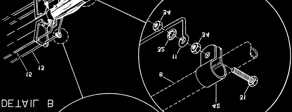
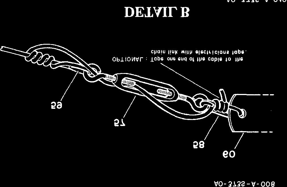
22 Lightning Protection For proper lightning protection you must ground your antenna supporting structure. Grounding will ensure noise-free operation and low SWR. A proper ground consists of a 1/2" x 8' copper-clad steel ground rod driven into the ground approximately 12 inches away from the concrete tower base. Connect the tower to the ground rod using #8 copper wire and commercial noncorrosive ground clamps. Attachment of Feedline Strip your coaxial cable (maximum 7 inches) and install solder lugs (not supplied) and connect to the driven element as shown in Figure 13. An RF choke made from 12 turns of RG-213/u coax in a 14 inch diameter circle is recommended with a split coax feed. Seal An alternative is to use a Hy-Gain BN ohm balun for easy connection to your coax cable. "Pigtail" leads of #10 gauge stranded wire 7 inches long should be used from the balun to the tubing clamps. Use a good quality 50 ohm coaxial transmission line such as Beldon 8214 (foam) or Belden 8237, 8267, or 9251 (solid). Take extra care when soldering connectors to foam dielectric coaxial cable. Weatherproof all connector, which will be exposed to rain or ice, with Coax-Seal or another similar Attach the transmission line to the feedpoint and tighten the hardware securely. Tape the coax to the boom to ensure good strain relief. Boom Support Assembly Select the 1 1/4" element compression clamps (Item No. 66), the boom support straps (Item No. 61),1/4"-20 x 13/4" Bolts (Item No. 69), and 1/4" square nuts (Item No. 33), and assemble on the director and reflector elements 10 inches from the center of the boom. See Figure 14. Tighten the bolts securely. Select the four (4) 20 foot boom support cables (Item No. 52), wire rope thimbles (Item No. 59) and turnbuckles (Item No. 57). cable to each of the four boom supports straps (Item No. 61) already assembled in the previous step. See Figure 14. Measure the distance between the thimble (Item No. 59) closest to the element and the center of the turnbuckle (Item No. 57) with the wire taut and the eyebolts screwed all the way in. This distance should be approximately 17 feet. Leave the excess wire, which should be about 2 feet long, to later thread through the turnbuckle as shown in Figure 14, Detail B. NOTE: If you have previously assembled the Discoverer 7-2, then you should disassemble the mast clamps (Item No. 60), chain links (Item No. 58) and turnbuckles (Item No. 57) as these will be used again. Item Numbers 59, 52, 61, and 62 may be discarded from the old antenna. Select the two open-end chain links (Item No. 58) and the two mast clamps (Item No. 60). Thread on chain link into the outer hole of a mast clamp and then through the two eyebolts attached to the two cable assemblies coming from the director element. See Figure 14, Details B and C. Squeeze the chain link closed with a pair of hand pliers. Do the same thing for the remaining chain link, mast clamp and two cable assemblies coming from the reflector element. Hold the two mast clamps together over the boom-to-mast brackets. If you cannot lift the two clamps at least 3 feet above the brackets, or if the wires are not tensioned equally, then adjust the length of the wires between the thimbles until these conditions are met. The turnbuckles should be adjusted for maximum length. Tape the mast clamps onto the boom on either side of the boom-to-mast bracket, so that you can retrieve them once you and the antenna are at the top of your tower. The boom support wires must be routed over the top of the driven element! The 3/8 inch hardware may be inserted through each clamp or carried separately up the tower. Coax-Seals is a registered trademark of Universal Electronics, Inc.


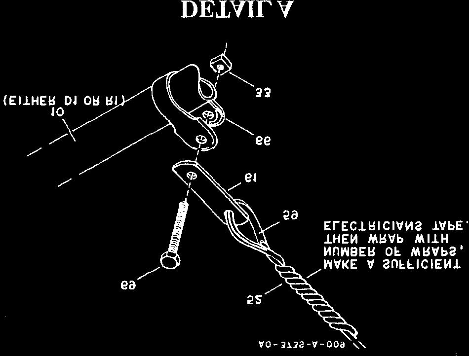

23 Figure 14 Boom Support Assembly
24 CHAPTER 4 INSTALLATION Installation Make sure all element compression clamps and anchor screws are securely tightened. Also, make sure all beta match hardware is tightened securely and free of corrosion. IMPORTANT: The Discoverer 7-3 is a very large and heavy antenna and requires consideration as to how you are going to get it to the top of the tower. Thoroughly read this section before beginning to install your antenna. Installation on a Crank-Up Tower Crank the tower down completely or as low as it will go, and block all sections from moving by using a 2" x 4" piece of wood or a solid iron bar for heavier towers. The block should be inserted through the lattice structure before the tower is completely down, then the tower can be cranked down until the block takes the weight off of the winch. Use a ladder to reach the top of the tower. NEVER CLIMB THE LATTICE STRUC- TURE OF ANY CRANK-UP TOWER! Attach the mast to the tower and rotator. (The cast aluminum boom-to-mast brackets (Item No. 1) should be installed on the mast as shown in Figure 15.) Attach a gin pole to the tower to assist in lifting the Discoverer 7-3. This antenna weighs approximately 96 pounds, therefore, make sure that your rope is strong enough and that you have enough help on the ground to lift. held by the ground crew, so that the guide rope can be retrieved. Attaching the Antenna to the Mast When the antenna reaches the mast bracket, the four (4) 5" bolts should be inserted through the holes in the mast bracket and secured using 5/16"-181ockwashers and nuts (Item Nos. 23, 27, & 26). Tighten all bolts securely. You may wish to use a deep-well socket set to tighten these bolts. You may notice a considerable amount of sag in the boom. This is normal. The mast clamps may now be untaped from the boom and attached to the mast, as shown in Figure 14, Detail C. Loosen the turnbuckles and slide the entire assembly up the mast until the boom support wires are straight. Tighten the 3/8"-16 bolts securely. Take up any slack in each wire with the turnbuckles, until the boom is level. When taut, tie off the turnbuckles. See Figure 14, Detail B. Tape the transmission line to the boom and mast for strain relief. Attach the lifting rope to the balance point of the antenna. The lifting rope should be fed through the gin pole or other pulley arrangement attached to the tower. The other end should be at ground level, available to the ground crew for lifting. Guide ropes may be loosely looped over the boom ends and used by the ground crew to guide the antenna away from the tower and ladder. The guide rope's two loose ends should be
25 Figure 15 Attaching Boom-to- Mast Bracket Other Types of Towers When installing the Discoverer 7-3 on a guyed tower, you may wish to use a different guide system. If you have insulators on your guy wires, you will need to keep the antenna away from the guy wires as well as the tower. You may wish to use two ropes attached together at the top of the tower and attached to the ground about 15 feet apart. These two ropes can then be used to slide the antenna on as if is also being lifted. The two ropes will need to be far enough from the tower base to allow some sag and still support the antenna away from the guy wires. WARNING Installation of this product near power lines is dangerous. For your safety follow the instructions.
, check the VSWR across each band from 7.0 to 7.3 MHz. Record this information for future reference. See Attachment 1 in Chapter 5.")
26 Operation Connect the end of your transmission line to a good quality SWR meter or Thruline wattmeter and then to your radio. While using lower power (less than 200 watts output), check the VSWR across each band from 7.0 to 7.3 MHz. Record this information for future reference. See Attachment 1 in Chapter 5. Check the VSWR periodically to ensure proper operation. This completes your installation of the Discoverer 7-3. Happy DX'ing! Maintenance The Discoverer 7-3 antenna is designed to be relatively maintenance free. All hardware, except for seven (7) long bolts used in the boomto-mast bracket, are made of passivated stainless steel. The seven long bolts are plated with a thick layer of cadmium with protective coating of clear chromate. The internal tooth type lockwashers used in this antenna are made of a slightly magnetic grade of stainless steel. The element compression clamps are made of T304 passivated stainless steel. All other metallic parts are aluminum. All insulators are made of either black polyethylene, black CycolacO or black fiberfilled styron. Hy-Gain now recommends genuine Penetrox- AO from Burndy Corporation for use as an antielectrolytic compound within element assemblies. This prevents aluminum oxide from forming on the aluminum surface, thereby maintaining high electrical conductivity between element sections, especially in coastal environments. No other type of conductive paste should be used. Penetrox-AO can be purchased in most electrical supply outlets. A light amount of clear lacquer or an acrylic spray may be used to coat the exterior surface of the element assemblies if heavy oxidation is likely to occur. Heavy oxidation of aluminum may occur if the antenna is installed within 5 miles of salt water. When storing this antenna (or if awaiting installation), care should be taken not to damage any assembly. Do not leave the elements in a grassy area, as wet grass will stain the aluminum. VSWR Calculations When using a meter, which indicates forward and reflected power levels, you may wish to convert these readings to VSWR. The correct formulas are: For example, if the forward power is 120 watts and the reflected power is 8 watts 'I'hruline is a registered trademark of Bird Electronics. Cycolac Is a registered trademark of Borg-Warner. Penetrox- A is a registered trademark of Burndy Corporation.
27 Service CHAPTER 5 SERVICE If you are encounter technical problems and need assistance, you should contact Hy-Gain Customer Service Department. All requests, inquires, warranty claims, or for ordering replacement parts, contact: Hy-Gain 308 Industrial Park Road Starkville, Mississippi USA Phone:
28 Height of Antenna: NOTES: Attachment l
29 PARTS NOTE: Item Numbers may not necessarily be in numerical sequence and may appear more than one time, depending on how often a part is used or identical parts being placed in different parts packs. Item No. Part No. Description 372S Qty 373S Bracket, Cast Aluminum Mast Bracket, Casting-to-Boom Clamp, Boom-to-Bracket Bracket, Element-to-Boom, # (Not Used) Tube, Element, R5, 7/16" x 68" Tube, Element, DE4, R4 & D4,5/8" x 26" Tube, Element, DE3, R3 & D3,7/8" x 55" Tube, Element, DE2, R2 & D2, 1" x 51" Tube, Element, DE1, RI & D1, 11/4" x 83" "Hairpin", LLW 1, "Hairpin", LLW2, 28" "Hairpin", LLW3, 63 1/2" "Hairpin", LLW4, 3 1/2" "Hairpin", I LW5, 63 1/2" Insulator, Element, 40 Meter Insulator, Element, DE Beta Rod, 1/4 x 72" (Not Used) Bracket, Element-to-Boom, # Tube, Element, DE5 & D5, 7/16" x 58" Tube, Boom, 2" x 83" Tube, Boom, 2" x 54 3/4", swaged Cable, Boom Support, 1/8" x 20 ft Tube, Boom, 2" x 81", swaged Tube, Boom, Insert, 13/4" x 711/8 " Parts Pack, 3728, Hardware Parts Pack, 373S, Hardware Bolt, round head, #6-32 x 2" Nut, hex, # Lockwasher, internal, # Bolt, hex head, tap, 5/16"-18 x 5" Bolt, hex head, tap, 5/16"-18 x 3 1/ Bolt, hex head, 5/16"-18 x 2 3/4" Bolt, hex head, 5/16"-18 x 21/2" Nut, hex, 5/16" Lockwasher, split, 5/16" Bolt, 1/4"-20 x 3/8" Bolt, hex head, 1/4"- 20 x 11/ Bolt, hex head, 1/4"- 20 x 3/4"
30 PARTS LIST Item No. Part No. Description Qty 372S 373S Parts Pack, 373S, Hardware (cont.) Bolt, hex head, 1/4"-20 x 11/ Bolt, hex head, 1/4"-20 x 21/ Bolt, hex head, 1/4"-20 x 13/ Lockwasher, internal, 1/4" Nut, square, 1/4" Nut, hex, 1/4" Bolt, hex head, # x 2" Bolt, hex head, # x 1/2" Bolt, hex head, # x 1" Bolt, hex head, #10-24 x 11/2 " Nut, hex, # Nut, square, # Lockwasher, internal, # (Not Used) Parts Pack, 372S, Clamps Clamp, Tubing 7/8" Clamp,Tubing, # (Not Used) Clamp, Beta Shorting Clamp, Tubing, 11/ Parts Pack, 3725, Insulators Caplug, black, 2" Caplug, black, 7/16" Insulator, Rod Support Parts Pack, 3725, Boom Support Turnbuckle, Eye and Eye, 7/32" x 2" Chain Link, Open-End, 3/16" Thimble, Wire Rope, 5/32" Mast Clamp, Boom Support, 5/ Strap, Boom Support... : Clamp, Boom Support, 2" LD Bolt, hex head, 3/8"-16 x 2" Bolt, hex head, 1/4"-20 x 3/ Lockwasher, internal, 1/4" Nut, hex, 1/4" Nut, hex, 3/8" Lockwasher, internal, 3/8"...2 0
31 Item No. Part No. PARTS LIST Description 3725 Qty 373S Parts Pack, 3735, Clamps and Miscellaneous Clamp, Tubing 7/8" Clamp, Tubing, # (Not Used) Turnbuckle, Eye and Eye, 7/32" x 2" Caplug, black, 7/16" Insulator, Rod Support Thimble, Wire Rope, 5/32" Strap, Boom Support Clamp, Compression, 11/4' Converting American Measurements to Metric Use this scale to identify lengths of bolts, diameters of tubes, etc.. The American inch (") and foot (') can be converted to centimeters in 1 inch (1") = cm 1 foot (1') = cm
DB Duo-Monoband Beam 7 - Element, 12 and 17 Meter INSTRUCTION MANUAL. General Description
 308 Industrial Park Road Starkville, MS 39759 USA Ph: (662) 323-9538 FAX: (662) 323-6551 DB- 1217 Duo-Monoband Beam 7 - Element, 12 and 17 Meter INSTRUCTION MANUAL General Description The Hy-Gain DB-1217
INSTRUCTION MANUAL VB-66DX. 6-Meter 6-Element Beam. Preparation For Assembly. General Description
 VB-66DX 308 Industrial Park Road Starkville, MS 39759 USA Ph: (662) 323-9538 FAX: (662) 323-6551 6-Meter 6-Element Beam INSTRUCTION MANUAL General Description The Hy-Gain Model 66DX is a full sized 6-
INSTRUCTION MANUAL. Specifications Electrical. Front-To-Back Ratio VSWR at Resonance Less than 1.5:1 Nominal Impedance. Mechanical
 300 Industrial Park Road, Starkville, MS 39759 Ph: (662) 323-8538 FAX: (662) 323-6551 TH-3JRS Tri-band HF 3 Elements Beam Covers 10, 15 and 20 Meters INSTRUCTION MANUAL WARNING Installation of this product
LJ element beam for 10 or 12 meters INSTRUCTION MANUAL. CAUTION: Read All Instructions Before Operating Equipment
 LJ-113 3 element beam for 10 or 1 meters INSTRUCTION MANUAL CAUTION: Read All Instructions Before Operating Equipment 308 Industrial Park Road Starkville, MS 39759 USA Tel: 66-33-9538 Fax: 66-33-6551 VERSION
MODEL DB-1015A 10- and 15-Meter Duo-Band Antenna Order No. 330
 MODEL DB-1015A 10- and 15-Meter Duo-Band Antenna Order No. 330 HY-GAIN ELECTRONICS CORPORATION 8601 Northeast Highway 6 Lincoln, Nebraska 68505 Telephone 464-9151 Area Code 402 TABLE OF CONTENTS page SECTION
INSTRUCTION MANUAL. Model VB-215DX MECHANICAL DESIGN GENERAL DESCRIPTION ELECTRICAL DESIGN. 2 Meter 15 Element Yagi for SSB/CW
 Model VB-215DX 2 Meter 15 Element Yagi for SSB/CW INSTRUCTION MANUAL GENERAL DESCRIPTION The Hy-Gain Model 215DX is a high performance yagi antenna for SSB/CW DXing in the Amateur 2 meter band. It features
Cushcraft. Amateur Radio Antennas BOLP Element 5 Band Optimized Log Periodic Antenna INSTRUCTION MANUAL
 Cushcraft Amateur Radio Antennas BOLP-1013 13 Element 5 Band Optimized Log Periodic Antenna INSTRUCTION MANUAL CAUTION: Read All Instructions Before Operating Equipment VERSION 1A Cushcraft Amateur Radio
INSTRUCTION MANUAL ORDER NO. V3R MODEL V3R. Collinear Gain Vertical for MHz
 ORDER NO. V3R MODEL V3R Collinear Gain Vertical for 216-225 MHz INSTRUCTION MANUAL General Description The new Hy-Gain V3R VHF antenna is a collinear 5/8-wave omnidirectional vertical antenna for the 216-225
INSTRUCTION MANUAL V-42R. Dual Band Collinear Gain Vertical for MHz and GENERAL DESCRIPTION
 308 Industrial Park Road, Starkville, MS 39759 USA Ph: (662) 323-9538 FAX: (662) 323-6551 V-42R Dual Band Collinear Gain Vertical for 144-148 MHz and 436-450 INSTRUCTION MANUAL GENERAL DESCRIPTION The
INSTRUCTION MANUAL for MODEL TH6-DX "THUNDERBIRD" (389)
") INSTRUCTION MANUAL for MODEL TH6-DX "THUNDERBIRD" (389) HY-GAIN ELECTRONICS CORPORATION, N. E. Hwy #6 at Stevens Creek, Lincoln, Nebraska 65801 Telephone 434-6331 INTRODUCTION Ely-Gain's new Model TH6-DX
INSTRUCTION MANUAL for MODEL TH6-DX "THUNDERBIRD" (389) HY-GAIN ELECTRONICS CORPORATION, N. E. Hwy #6 at Stevens Creek, Lincoln, Nebraska 65801 Telephone 434-6331 INTRODUCTION Ely-Gain's new Model TH6-DX
Cushcraft. Amateur Radio Antennas DB-46M8EL. Dual band 6 and 4 Meter, 8 Element Beam Antenna INSTRUCTION MANUAL
 Cushcraft Amateur Radio Antennas DB-46M8EL Dual band 6 and 4 Meter, 8 Element Beam Antenna INSTRUCTION MANUAL CAUTION: Read All Instructions Before Operating Equipment VERSION 1B Cushcraft Amateur Radio
Cushcraft. Amateur Radio Antennas LFA-6M5EL. 6 Meter 5 Element Loop Feed Antenna INSTRUCTION MANUAL
 Cushcraft Amateur Radio Antennas LFA-6M5EL 6 Meter 5 Element Loop Feed Antenna INSTRUCTION MANUAL CAUTION: Read All Instructions Before Operating Equipment VERSION 1A Cushcraft Amateur Radio Antennas 308
INSTRUCTION MANUAL. Model 18AVQII Five Band Vertical Antenna 10, 15, 20, 40, 80 Meter. General Description. Theory of Operation
 Model 18AVQII Five Band Vertical Antenna 10, 15, 20, 40, 80 Meter 308 Industrial Park Road Starkville, MS 39759 (662) 323-9538 Fax: (662) 323-5803 INSTRUCTION MANUAL General Description The Hy-Gain 18AVQII
INSTRUCTION MANUAL. Specifications Mechanical. 1 5/8 to 2 1/16 O.D. (41mm to 52mm)
") 308 Industrial Park Road Starkville, MS 39759 USA Ph: (662) 323-9538 FAX: (662) 323- General Description Model VB-25FM 2-Meter 5 Elements Beam INSTRUCTION MANUAL This antenna is a 5-element, 2-meter beam
308 Industrial Park Road Starkville, MS 39759 USA Ph: (662) 323-9538 FAX: (662) 323- General Description Model VB-25FM 2-Meter 5 Elements Beam INSTRUCTION MANUAL This antenna is a 5-element, 2-meter beam
Model VB-23FM 2-Meter 3-Element Beam
 308 Industrial Park Road Starkville, MS 39759 USA Ph: (662) 323-9538 FAX: (662) Model VB-23FM 2-Meter 3-Element Beam [ INSTRUCTION MANUAL Figure 1 Overall View and Boom Detail GENERAL DESCRIPTION This
Hy-gain. Method 1 : Completely assemble the antenna on the ground then hoist it into position using a setup as shown in Figure 1.
 Hy-gain The Hy-Gain TH6-DXX "Super Thunderbird" is a 6-element beam designed to operate on 10, 25 and 20 meters. It has four active elements on 10-meters and three active elements on 15 and 20 meters.
TELEX. iiilhiijiri INSTRUCTION MANUAL ORDER NO. 411 TELEX COMMUNICATIONS, INC ALDRICH AVE SO. MINNEAPOLIS. MN U.SA.
 TELEX. iiilhiijiri TELEX COMMUNICATIONS, INC. 9600 ALDRICH AVE SO. MINNEAPOLIS. MN 55420 U.SA. INSTRUCTION MANUAL ORDER NO. 411 Base Station, 5-Element Beam Antenna This antenna is a five element, Citizens
INSTRUCTION MANUAL. Model 18AVQII Five Band Vertical Antenna 10, 15, 20, 40, 80 Meter
 Model 18AVQII Five Band Vertical Antenna 10, 15, 20, 40, 80 Meter 308 Industrial Park Road Starkville, MS 39759 (662) 323-9538 Fax: (662) 323-5803 INSTRUCTION MANUAL General Description The Hy-Gain 18AVQII
M2 Antenna Systems, Inc. Model No: 20M5LD
 M2 Antenna Systems, Inc. Model No: 20M5LD SPECIFICATIONS: Model... 20M5LD Frequency Range... 14.0 14.350 MHz *Gain (Full Band)... 10.2 dbi Typical Front to back... 23 db Typical Beamwidth... E=50 / H=66
M2 Antenna Systems, Inc. Model No: 20M6-125
 M2 Antenna Systems, Inc. Model No: 20M6-125 SPECIFICATIONS: Model... 20M6-125 Frequency Range... 14.0 14.350 MHz *Gain, (FS) / Over gnd... 11.19dBi / 16.6dBi @70 Front to back... 25 db Typical Beamwidth...
Directive Systems & Engineering 2702 Rodgers Terrace Haymarket, VA
 Directive Systems & Engineering 2702 Rodgers Terrace Haymarket, VA 20169 1628 www.directivesystems.com 703 754 3876 K1JX DESIGNED 6 ELEMENT 50 MHZ YAGI, DSEJX6 50 INTRODUCTION The Directive Systems DSEJX6-50
TELEX, liutiiilio"i TELEX COMMUNICATIONS, INC ALDRICH AVE. SO. MINNEAPOLIS. MN USA
 TELEX, liutiiilio"i TELEX COMMUNICATIONS, INC. 9600 ALDRICH AVE. SO. MINNEAPOLIS. MN 55420 USA INSTRUCTION MANUAL ORDER NO. 410 General This antenna is a five-element, Citizens Band beam with a forward
TELEX COMMUNICATIONS, INC ALDRICH LIVE SO. MINNEAPOLIS. MN U S A. /~g-~~~~r iu IORDER NO. 337s
 IkEfEX N TELEX COMMUNICATIONS, INC. 300 ALDRICH LIVE SO. MINNEAPOLIS. MN 55420 U S A /~g-~~~~r iu IORDER NO. 337s MAN A I MODEL V4S Collinear Gain Vertical for 420450 MHz PN801910 General Description The
PREPARATION FOR ASSEMBLY
 GENERAL DESCRIPTION The Hy-Gain Model 216 SAT is a high-performance "OSCAR" (Orbiting Satellite Carrying Amateur Radio) satellite antenna for the 145.8-146.0 MHz frequency hand. It features polarization
PAC-12 Kit Contents. Tools Needed Soldering iron Phillips screwdriver Wire stripper Wrenches, 7/16 and 1/2 Terminal crimp tool Pliers Solder
 PAC-2 Kit Contents Part Quantity Screws: 8/32 x 3/8 Screws: 8-32 x 5/6 Screw: 8-32 x /4 #8 internal tooth washers #8 solder lug ring terminals Bolt: Aluminum, /4-20 x.5 /4 internal tooth washer Nut: Aluminum
TZ-RD-1740 Rotary Dipole Instruction Manual
 TZ-RD-1740 17/40m Rotary Dipole Instruction Manual The TZ-RD-1740 is a loaded dipole antenna for the 40m band and a full size rotary dipole for the 17m band. The antenna uses an aluminium radiating section
M2 Antenna Systems, Inc. Model No: 40M3L
 M2 Antenna Systems, Inc. Model No: 40M3L SPECIFICATIONS: Model... 40M3L Frequency Range... 7.0-7.3 MHz X 150 khz Gain... 6.6 dbi Front to back... 23 db Beamwidth... E=62 Feed type... Hair pin match Feed
AV-12AVQ Triband HF Vertical 10, 15, 20-Meter INSTRUCTION MANUAL
 308 Industrial Park Starkville, MS 39759 USA Ph: (662) 323-9538 FAX: (662) 323-6551 AV-12AVQ Triband HF Vertical 10, 15, 20-Meter INSTRUCTION MANUAL General Description This vertical antenna is designed
K1FO 12 ELEMENT 144/147 MHz YAGI
 K1FO 12 ELEMENT 144/147 MHz YAGI WARNING: INSTALLATION OF THIS PRODUCT NEAR POWER LINES IS DANGEROUS. FOR YOUR SAFETY FOLLOW THE INSTALLATION DIRECTIONS. Ariane Arrays, Inc. Copyright 2006 201 Hopedale
M2 Antenna Systems, Inc. Model No: 10-30LP8
 M2 Antenna Systems, Inc. Model No: 10-30LP8 SPECIFICATIONS: Model... 10-30LP8 Frequency Range... 10-30 MHz Continuous *Gain free space / 65... 5.2 dbi / 10.5 dbi 10-30 Front to back... 15 db 10-30 MHz
M2 Antenna Systems, Inc. Model No: 2M7
 M2 Antenna Systems, Inc. Model No: 2M7 SPECIFICATIONS: Model... 2M7 Frequency Range... 144 To 148 MHz *Gain... 12.3 dbi Front to back... 20 db Typical Beamwidth... E=43 H=50 Feed type... T Match Feed Impedance....
Installation Instructions Hustler 6-BTV Trap Vertical
 Installation Instructions Hustler 6-BTV Trap Vertical ASSEMBLY 1. Check the package contents against the parts list on page 2. 2. WARNING. Installation of this product near power lines is dangerous. For
M2 Antenna Systems, Inc. Model No: 10-30LP8
 M2 Antenna Systems, Inc. Model No: 10-30LP8 VSWR 2:1 TYPICAL VSWR @ 70 FT. 2:1 1.5:1 1.5:1 1.2:1 1.2:1 10 14 MHz 11 12 13 17 15 16 18 19 20 21 22 23 24 25 26 27 28 29 30 SPECIFICATIONS: Model...10-30LP8
M2 Antenna Systems, Inc. Model No: 2M5WL
 M2 Antenna Systems, Inc. Model No: 2M5WL SPECIFICATIONS: Model... 2M5WL Frequency Range... 144 To 148 MHz *Gain... 16.84 dbi Front to back... 22 db Typical Beamwidth... E=26 H=29 Feed type... T Match Feed
JK M Hi-Q Coil Loaded Rotatable Dipole Version
 JK-401 40M Hi-Q Coil Loaded Rotatable Dipole 2018 Version 72 Grays Bridge Road, Unit D, Brookfield, CT 06804 845.228.8700 (TEL) 845.279.5526 (FAX) info@jkantennas.com LAST UPDATED: 02-01-2018 JK Antennas
INSTRUCTION MANUAL. Model BN-4000B. High Power Balun for Beams with Type SO-239. Construction. General Description. Mounting on Boom or Mast
 308 Industrial Park Starkville, MS 39759 USA Ph: (662) 323-9538 FAX: (662) 323 6551 Model BN-4000B High Power Balun for Beams with Type SO-239 INSTRUCTION MANUAL General Description The BN-4000 is a current-type
M2 Antenna Systems, Inc. Model No: YAGI ANTENNA
 M Antenna Systems, Inc. Model No: 4.5-7 YAGI ANTENNA SPECIFICATIONS: Model... 4.5-7 Frequency Range... 4.0 To 4.5 MHz *Gain... 0 To 7 dbi Front to back... 0 db over the rear 80 Beamwidth... E=44 H=50 typical
M2 Antenna Systems, Inc. Model No: 2MCP22
 M2 Antenna Systems, Inc. Model No: 2MCP22 SPECIFICATIONS: Model... 2MCP22 Frequency Range... 144 To 148 MHz *Gain... 14.39 dbic Front to back... 25 db Typical Elipticity... >3db Beamwidth... 38 Feed type...
MA5B 20 / 17 / 15 / 12 / 10 Meter Beam Antenna
 ASSEMBLY AND INSTALLATION INSTRUCTIONS NE 20 / 17 / 15 / 12 / 10 Meter Beam Antenna 951485_GF_AB WARNING THIS ANTENNA IS AN ELECTRICAL CONDUCTOR. CONTACT WITH POWER LINES CAN RESULT IN DEATH, OR SERIOUS
Directive Systems & Engineering 2702 Rodgers Terrace Haymarket, VA
 Directive Systems & Engineering 2702 Rodgers Terrace Haymarket, VA 20169-1628 www.directivesystems.com 703-754-3876 25 Element 7.4 wl. K1FO Designed Yagi, Model DSEFO432-25 ELECTRICAL SPECIFICATIONS Frequency
Assembly Instructions: Bencher Skylark
 Assembly Instructions: Bencher Skylark Tools Required: Pop Rivet Tool Tape Measure Hex Wrenches Screwdriver Several Disposable Rags Two Saw Horses Several boxes or bowls to hold fasteners and small parts
M2 Antenna Systems, Inc. Model No: 2M4
 M2 Antenna Systems, Inc. Model No: 2M4 SPECIFICATIONS: Model... 2M4 Frequency Range... 144 To 148 MHz *Gain... 9.6 dbi Front to back... 20 db Typical Beamwidth... E=54 H=74 Feed type... T Match Feed Impedance....
JK-65 Five Element 6M Yagi
 JK-65 Five Element 6M Yagi PO Box 266, Croton Falls, NY 10519-0266 845.228.8700 (TEL) 845.279.5526 (FAX) info@jkantennas.com Page 1 of 8 JK Antennas Limited Warranty and Liability JK Antennas ( Manufacturer
MFJ-1762 Instruction Manual
 MFJ-1762 Instruction Manual INTRODUCTION Thank you for purchasing the MFJ-1762 three-element six-meter Yagi. The MFJ-1762 is a light-weight directional antenna especially designed for installation with
THIS SHOULD TWEAK YOUR IMAGINATION
 10-27-05 THIS SHOULD TWEAK YOUR IMAGINATION SPECIFICATIONS FOR SINGLE ANTENNA MODEL NUMBER... 432EME-12 FREQUENCY... 430-436 MHz GAIN... 14.4 dbd FRONT TO BACK... 23 db VSWR... 1.2:1 TYPICAL BEAMWIDTH...
Installation Instructions Hustler 6-BTV Trap Vertical
 Installation Instructions Hustler 6-BTV Trap Vertical ASSEMBLY 1. Check the package contents against the parts list on page 2. 2. WARNING. Installation of this product near power lines is dangerous. For
CSS Central Mount System
 CSS-20 Installation Manual CSS-20 Safety Notifications Below are the installation instructions for the CSS-20-2 Long Span Beam Mounting System. Please read these safety notifications prior to beginning
M2 Antenna Systems, Inc. Model No: 40M2L
 M2 Antenna Systems, Inc. Model No: 40M2L SPECIFICATIONS: Model...40M2L Frequency Range...6.9-10 MHz X 150 khz Gain...5.5 dbi Front to back...13 15 db Beamwidth...E=74 Feed type...hair pin match Feed Impedance....50
MFJ Foot Self-Supporting Vertical Antenna
 MFJ-2990 43-Foot Self-Supporting Vertical Antenna INTRODUCTION The MFJ-2990 is a 43-foot self-supporting vertical antenna that covers 160-6 meters with the use of an wide range antenna tuner. Because the
A short, off-center fed dipole for 40 m and 20 m by Daniel Marks, KW4TI
 A short, off-center fed dipole for 40 m and 20 m by Daniel Marks, KW4TI Version 2017-Nov-7 Abstract: This antenna is a 20 to 25 foot long (6.0 m to 7.6 m) off-center fed dipole antenna for the 20 m and
JK BigTri. 3-Band Yagi (20M/15M/10M) 36Ft Boom
 36Ft Boom") JK BigTri 3-Band Yagi (20M/15M/10M) 36Ft Boom 72 Grays Bridge Road, Unit D, Brookfield, CT 06804 845.228.8700 (TEL) 845.279.5526 (FAX) info@jkantennas.com UPDATED : FEB 2017 JK Antennas Limited Warranty
JK BigTri 3-Band Yagi (20M/15M/10M) 36Ft Boom 72 Grays Bridge Road, Unit D, Brookfield, CT 06804 845.228.8700 (TEL) 845.279.5526 (FAX) info@jkantennas.com UPDATED : FEB 2017 JK Antennas Limited Warranty
DB-2345 INSTRUCTION MANUAL. 308 Industrial Park Road Starkville, MS USA ph:(662) Fax: (662) Made in USA
 Fax: (662) Made in USA") 308 Industrial Park Road Starkville, MS 39759 USA ph:(662) 323-9538 Fax: (662) 323-5803 DB-2345 INSTRUCTION MANUAL Made in USA Hy-Gain DB2345 Dual-Band Beam INTRODUCTION The Hy-Gain DB2345 is a compact
308 Industrial Park Road Starkville, MS 39759 USA ph:(662) 323-9538 Fax: (662) 323-5803 DB-2345 INSTRUCTION MANUAL Made in USA Hy-Gain DB2345 Dual-Band Beam INTRODUCTION The Hy-Gain DB2345 is a compact
Cisco Aironet 2.4-GHz/5-GHz 8-dBi Directional Antenna (AIR-ANT2588P3M-N)
") Cisco Aironet.4-GHz/5-GHz 8-dBi Directional Antenna (AIR-ANT588P3M-N) This document outlines the specifications for the Cisco Aironet AIR-ANT588P3M-N.4/5-GHz 8-dBi 3-Port Directional Antenna with N-connectors
Cisco Aironet.4-GHz/5-GHz 8-dBi Directional Antenna (AIR-ANT588P3M-N) This document outlines the specifications for the Cisco Aironet AIR-ANT588P3M-N.4/5-GHz 8-dBi 3-Port Directional Antenna with N-connectors
M2 Antenna Systems, Inc. Model No: 7&10-30LP8
 M2 Antenna Systems, Inc. Model No: 7&10-30LP8 2:1 100KHz BANDWIDTH@ 1.8:1 VSWR 1.5:1 6.9 7.0 7.1 10 FREQUENCY (MHZ) 20 SPECIFICATIONS: Model...7&10-30LP8 Skip log Frequency Range...10-30 MHz Continuous
WARNING EXTREME CARE MUST BE USED FOR YOUR SAFETY
 WARNING EXTREME CARE MUST BE USED FOR YOUR SAFETY PLANNING Plan your installation carefully. If you use volunteer helpers be sure that they are qualified to assist you. Make certain that everyone involved
CMA-455 Suspended Ceiling-Tile Reinforcing Kit
 INSTALLATION INSTRUCTIONS CMA-455 Suspended Ceiling-Tile Reinforcing Kit The provides a sturdy support for LCD/DLP hanging brackets (and certain other products) when installing these products in a suspended
Yagi and Omni Antennas Installation Manual
 Yagi and Omni Antennas Installation Manual 25500445 Rev. A0 0218 Printed in U.S.A. Copyright 2018 Federal Signal Corporation Limited Warranty This product is subject to and covered by a limited warranty,
M2 Antenna Systems, Inc. Model No: 435XP50
 M2 Antenna Systems, Inc. Model No: 435XP50 SPECIFICATIONS: Model... 435XP50 Frequency Range... 430 To 436 MHz *Gain... 19.2 dbi Front to back... 22 db Typical Cross pol. isolation... >20 db Typical Beamwidth...
MFJ-2982 Feather-Lite 80-6 Meter Vertical Antenna
 MFJ-2982 Feather-Lite 80-6 Meter Vertical Introduction: The MFJ-2982 is a lightweight 31-foot fiberglass antenna designed to mount on any convenient post, mast, or a suitable wide-stance tripod such as
M2 Antenna Systems, Inc. Model No: 450CP34
 M2 Antenna Systems, Inc. Model No: 450CP34 SPECIFICATIONS: Model... 450CP34 Frequency Range... 435 To 455 mhz *Gain... 16.0 dbi Front to back... 22 db Typical Beamwidth... 28 Circular Feed type... T Match
JK NAVASSA-5. 5-Band Yagi (20M/17M/15M/12M/10M) Optional 6M Add-on Kit Available
 Optional 6M Add-on Kit Available") JK NAVASSA-5 5-Band Yagi (20M/17M/15M/12M/10M) Optional 6M Add-on Kit Available 72 Grays Bridge Road, Unit D, Brookfield, CT 06804 845.228.8700 (TEL) 845.279.5526 (FAX) info@jkantennas.com Last Updated:
JK NAVASSA-5 5-Band Yagi (20M/17M/15M/12M/10M) Optional 6M Add-on Kit Available 72 Grays Bridge Road, Unit D, Brookfield, CT 06804 845.228.8700 (TEL) 845.279.5526 (FAX) info@jkantennas.com Last Updated:
M2 Antenna Systems, Inc. Model No: 456CP34
 M2 Antenna Systems, Inc. Model No: 456CP34 SPECIFICATIONS: Model... 456CP34 Frequency Range... 435 To 470 mhz *Gain... 16.0 dbi Front to back... 23 db Typical Beamwidth... 30 Circular Feed type... T Match
C O R P O R A T I O N
 ASSEMBLY AND INSTALLATION INSTRUCTIONS A4S 20 / 5 / 0 MeterBeam C O R P O R A T I O N 95279 (8/98) WARNING THIS ANNNA IS AN ELECTRICAL CONDUCTOR. CONTACT WITH POWER LINES CAN RESULT IN DEATH, OR SERIOUS
M2 Antenna Systems, Inc. Model No: 436CP30
 M2 Antenna Systems, Inc. Model No: 436CP30 SPECIFICATIONS: Model... 436CP30 Frequency Range... 432 To 440 MHz *Gain... 15.50 dbic Front to back... 18 db Typical Elipticity... 1.5 db Typical Beamwidth...
M2 Antenna Systems, Inc. Model No: 450CP26
 M2 Antenna Systems, Inc. Model No: 450CP26 SPECIFICATIONS: Model... 450CP26 Frequency Range... 445 To 455 mhz *Gain... 16.5 dbi Front to back... 21 db Typical Beamwidth... 30 Circular Feed type... T Match
hy-gain INSTRUCTION MANUAL AV-18HT Hy-Tower Vertical Antenna 10,15,20,40, and 80 Meters Specifications Mechanical
 hy-gain 308 Industrial Park Road Starkville, MS 39759 USA Ph: (662) 323-9538 FAX: (662) 323655 1 INSTRUCTION MANUAL AV-18HT Hy-Tower Vertical Antenna 10,15,20,40, and 80 Meters General Description The
M2 Antenna Systems, Inc. Model No: 10-30LP8-125
 M2 Antenna Systems, Inc. Model No: 10-30LP8-125 VSWR 2:1 TYPICAL VSWR @ 70 FT. 2:1 1.5:1 1.5:1 1.2:1 1.2:1 10 14 MHz 11 12 13 17 15 16 18 19 20 21 22 23 24 25 26 27 28 29 30 SPECIFICATIONS: Model...10-30LP8-125
MHz. ANT150D, D3, D6-9 DIPOLE AND DIPOLE ARRAY 1 TO 9 dbd
 138-174 MHz ANTD, D3, D6-9 DIPOLE AND DIPOLE ARRAY 1 TO 9 dbd The Telewave ANTD series consists of single, dual, and 4-element di pole array antennas with a precision phasing harness for optimum per formance.
CP6 6 Band Trap Vertical 80-6m
 CP6 6 Band Trap Vertical 80-6m Instruction Sheet The CP6 is a multi-band trap-vertical antenna for HF bands, covering the 80*, 40, 20, 15, 10m & 6m amateur bands. Made from heavy duty aluminum, the CP6
MFJ Instruction Manual Table of Contents
 Table of Contents MFJ-1768 Introduction...2 Choosing a Location for the Antenna...2 Tools and Time Requirements...3 MFJ-1768 Parts List...3 Safety Precautions...3 Assembly and Installation...4 Tuning...7
M2 Antenna Systems, Inc. Model No: KT31WARC
 M2 Antenna Systems, Inc. Model No: KT31WARC SPECIFICATIONS: Model... KT31WARC Frequency Range... 10.1-10.15 MHz **Selectable Frequency Range... 14.0-14.35 MHz **Selectable... (175 KHz / 2:1 VSWR Nominal)
CP6A. 6 Band Trap Vertical 75-6m
 CP6A 6 Band Trap Vertical 75-6m Instruction Sheet The CP6A is a multi-band trap-vertical antenna for HF bands, covering the 75*, 40, 20, 15, 10m & 6m amateur bands. Made from heavy duty aluminum, the CP6A
A Folding 5-Element Yagi for 144 MHz
 A Folding 5-Element Yagi for 144 MHz Steve Kavanagh, VE3SMA, April 2017 1. Introduction I have found antennas which fold up quickly to take less space in the car to be useful in VHF/UHF portable operating.
MFJ-1799 INSTRUCTION MANUAL. 2,6,10,12,15,17,20,30,40,80 METER Vertical Antenna. CAUTION: Read All Instructions Before Operating Equipment
 MFJ-799,6,0,,5,7,0,30,40,80 METER Vertical Antenna INSTRUCTION MANUAL CAUTION: Read All Instructions Before Operating Equipment 300 Industrial Park Road Starkville, MS 39759 USA Tel: 66-33-5869 Fax: 66-33-655
Pacific Antenna 20 and 40M Lightweight Dipole Kit
 Pacific Antenna 20 and 40M Lightweight Dipole Kit Diagram showing configuration and approximate lengths 8 6 16 9 16 9 8 6 Description The Pacific Antenna lightweight dual band, trap dipole kit provides
HFp. User s Guide. Vertical. entenna. 7 MHz 30 MHz Amateur Radio Antenna Plus 6-Meters
 User s Guide HFp Vertical 7 MHz 30 MHz Amateur Radio Antenna Plus 6-Meters The Ventenna Co. LLC P.O. Box 2998, Citrus Heights, CA, 956 www.ventenna.com entenna Table of Contents The HFp Antenna -------------------------------------------------------------------
MFJ ENTERPRISES, INC.
 Model MFJ-2910 INSTRUCTION MANUAL CAUTION: Read All Instructions Before Operating Equipment MFJ ENTERPRISES, INC. 300 Industrial Park Road Starkville, MS 39759 USA Tel: 662-323-5869 Fax: 662-323-6551 VERSION
Standard Pole Mount Parabolic Antenna Mounting Instructions 3 ft. (90cm) & 4 ft. (120cm)
 & 4 ft. (120cm)") 495 R Billerica Ave. N. Billerica, MA 01862 USA Tel: (978) 459-8800 Fax: (978) 459-3310 / 8814 www.radiowavesinc.com email: sales@radiowavesinc.com Standard Pole Mount Parabolic Antenna Mounting Instructions
495 R Billerica Ave. N. Billerica, MA 01862 USA Tel: (978) 459-8800 Fax: (978) 459-3310 / 8814 www.radiowavesinc.com email: sales@radiowavesinc.com Standard Pole Mount Parabolic Antenna Mounting Instructions
Pacific Antenna 20 and 40M Lightweight Dipole Kit
 Pacific Antenna 20 and 40M Lightweight Dipole Kit Diagram showing configuration and approximate lengths 8 3 16 9 16 9 8 3 Description The Pacific Antenna lightweight dual band, trap dipole kit provides
RMD3000 DPO3000 Series Rackmount Kit
 Instructions RMD3000 DPO3000 Series Rackmount Kit 071-2424-00 Warning The servicing instructions are for use by qualified personnel only. To avoid personal injury, do not perform any servicing unless you
Cisco Aironet 13.5-dBi Yagi Mast Mount Antenna (AIR-ANT1949)
") Cisco Aironet 13.5-dBi Yagi Mast Mount Antenna (AIR-ANT1949) Overview This document describes the 13.5-dBi Yagi mast mount antenna and provides instructions for mounting it. The antenna operates in the
Cisco Aironet 13.5-dBi Yagi Mast Mount Antenna (AIR-ANT1949) Overview This document describes the 13.5-dBi Yagi mast mount antenna and provides instructions for mounting it. The antenna operates in the
Soma Wind Generators
 Soma Wind Generators 19.5M WINH TOWER INSTALLATION MANUAL ERTIFIED to AS4100 Steel Structures ode AS3995 (1994) Design of Steel Lattice Towers and Masts AS1170.2 (1989) SAA Wind Loading ode Manufactured
Array Solutions OCF Series Dipoles
 OCF Series Dipoles Fig 1 Thank you and congratulations on your purchase of the, Off- Center Fed HF Dipole Antenna System. This antenna was built with the same quality workmanship and attention to detail
Warnings. Description. Prior to Installation Tools Needed
 Warnings Failure to act in accordance with the following may result in death or personal injury. The JT Strong Arm Stabilizer System is intended to eliminate chassis movement in travel trailers and fifth
MFJ-1835K34 40,30 METER ADD ON KIT FOR THE MFJ-1835 COBWEB ANTENNA INSTRUCTION MANUAL. CAUTION: Read All Instructions Before Operating Equipment
 MFJ-1835K34 40,30 METER ADD ON KIT FOR THE MFJ-1835 COBWEB ANTENNA INSTRUCTION MANUAL CAUTION: Read All Instructions Before Operating Equipment 300 Industrial Park Road Starkville, MS 39759 USA Tel: 662-323-5869
Assembly Instructions for the 10N6RDB Antenna
 Assembly Instructions for the 10N6RDB Antenna The 10N6RDB antenna comes from the factory almost completely assembled. All you have to do is install the 1/2 inch Aluminum tubing at both ends of the 10 Meter
ASSEMBLY AND INSTALLATION INSTRUCTIONS R , 12, 15, 17, 20, 30, 40 Meters (5/99) COMMUNICATIONS ANTENNAS
 COMMUNICATIONS ANTENNAS") ASSEMBLY AND INSTALLATION INSTRUCTIONS R7000 10, 12, 15, 17, 20, 30, 40 Meters COMMUNICATIONS ANTENNAS 951465 (5/99) WARNING THIS ANTENNA IS AN ELECTRICAL CONDUCTOR. CONTACT WITH POWER LINES CAN RESULT
ASSEMBLY AND INSTALLATION INSTRUCTIONS R7000 10, 12, 15, 17, 20, 30, 40 Meters COMMUNICATIONS ANTENNAS 951465 (5/99) WARNING THIS ANTENNA IS AN ELECTRICAL CONDUCTOR. CONTACT WITH POWER LINES CAN RESULT
MOSLEY DIPOLE CONVERSION KIT MODEL TA-40-KR
 MOSLEY DIPOLE CONVERSION KIT MODEL TA-40-KR TO CONVERT MODELS TA-31, TA-32, TA-33 AND TA-36 FOR OPERATION ON 40 METERS The high performance of your MOSLEY Antenna can only be achieved if the antenna is
PACKING LIST MACO V-5000
 PACKING LIST MACO V-5000 PART QTY O.D. SIZE LENGTH DESCRIPTION CHECKLIST T47P 4 5/8.050 36 Aluminum Tubing _ T43P 1 7/8.050 48 Aluminum Tubing _ T18P 1 3/4.050 48 Aluminum Tubing _ T15P 1 5/8.050 48 Aluminum
MQ-24SR Miniature Four band Hybrid Quad Antenna
 MQ-24SR Miniature Four band Hybrid Quad Antenna Most antennas are large heavy structures requiring heavy duty structures, rotors and lots of extra muscle during installation and lots of extra dollars before
JK-404 GRANDE Four Element Full Size 40M Yagi
 JK-404 GRANDE Four Element Full Size 40M Yagi PO Box 266, Croton Falls, NY 10519-0266 845.228.8700 (TEL) 845.279.5526 (FAX) info@jkantennas.com JK Antennas Limited Warranty and Liability JK Antennas (
ALWAYS ATTACH THE SAFETY ROPE TO A STABLE SUPPORT BEFORE ATTEMPTING TO ATTACH THE UNIVERSAL MOUNT TO A WINDOW FRAME OR RAIL.
 MFJ-1622 Introduction The MFJ-1622 Antenna was designed to provide portable or permanent HF communications on 40 through 10 meters and VHF on 6 and 2 meters. The universal mount design allows the user
MSP-WRTIDSKY1 Light Weight Suspended Ceiling Kit for use with Island Display Skybox
 INSTALLATION INSTRUCTIONS MSP-WRTIDSKY1 Light Weight Suspended Ceiling Kit for use with Island Display Skybox The MSP-WRTIDSKY1 Light Weight Suspended Ceiling Kit provides a sturdy support for LCD displays
Pacific Antenna 20 and 40M Lightweight Dipole Kit
 Pacific Antenna 20 and 40M Lightweight Dipole Kit Antenna diagram showing configuration and lengths when assembled 7 8 16 9 16 9 Description The Pacific Antenna lightweight dual band dipole kit provides
Table of Contents. MFJ-1778 G5RV Multiband Antenna
 Table of Contents MFJ-1778 G5RV Multiband Antenna Introduction... 1 Theory Of Operation... 1 80 meter band:... 1 40 meter band:... 1 30 meter band:... 2 20 meter band:... 2 17 meter band:... 2 15 meter
ABM International, Inc. Navigator Assembly Manual
 ABM International, Inc. 1 1.0: Parts List Tablet (Qty. 1) Tablet mount (Qty. 1) NOTE: Mount may appear and operate different then image below Control Box (Qty. 1) Motor Power Supply (Qty. 1) 2 X-axis motor
Model S9v. 43 Multiband Vertical Antenna Installation Guide
 Model S9v 43 Multiband Vertical Antenna Installation Guide. WARNING: INSTALLATION OF THIS PRODUCT NEAR POWERLINES IS DANGEROUS. FOR YOUR SAFETY, FOLLOW THE INSTALLATION DIRECTIONS. INTRODUCTION Thank you
Paradigm. Connect100 Installation Guide
 Paradigm GX Connect100 Installation Guide Paradigm GX Safe Use WARNING Radiation Hazard. Transmitter power levels are sufficient to cause blindness or other serious injury to body tissue. Do not power
HOUSE PARTS PACKED IN HOUSE BOX PARTS IN PLASTIC BAG (HARDWARE) PARTS IN SMALL PLASTIC BAG (FLOOR CLIPS) PARTS PACKED IN BUNDLE
 PARTS IN SMALL PLASTIC BAG (FLOOR CLIPS) PARTS PACKED IN BUNDLE") Check parts against this list before starting assembly. Refer to illustrations on pages 6 and 7 to view house parts. If any shortages are found, refer to Packing Slip for claim instructions. Item 3 5 6
Check parts against this list before starting assembly. Refer to illustrations on pages 6 and 7 to view house parts. If any shortages are found, refer to Packing Slip for claim instructions. Item 3 5 6
Alpha Delta Communications, Inc. Model DX-OCF Off-Center-Fed 7 Band Antenna
 Alpha Delta Communications, Inc. Model DX-OCF Off-Center-Fed 7 Band Antenna 75/80, 40, 20, 17, 12, 10, and 6 meters (50.0-51.0 MHz) NO TUNER REQUIRED! Installation Instructions One leg is 45 ft., the other