Sascha Stegen School of Electrical Engineering, Griffith University, Australia
|
|
|
- Geoffrey Taylor
- 5 years ago
- Views:
Transcription


1 Sascha Stegen School of Electrical Engineering, Griffith University, Australia
2 Electrical Machines and Drives Motors Generators Power Electronics and Drives
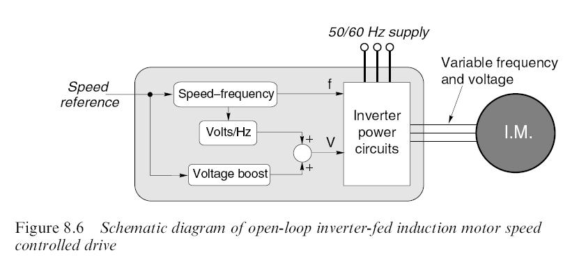
3 Open-loop inverter-fed

4 General arrangement of speed-controlled drive

5 General arrangement of inverter-fed variablefrequency induction motor speed-controlled drive. Most low and medium power inverters use MOSFET or IGBT devices, and may modulate at ultrasonic frequencies, which naturally result in relatively quiet operation.
 are")
6 The majority of inverters are 3-phase input and 3-phase output. Single-phase input versions are available up to about 5 kw, and some very small inverters (usually less than 1 kw) are specifically intended for use with single-phase motors.
7 Torque speed curves for inverter-fed induction motor with constant voltage frequency ratio
8 Typical torque speed curves for inverter-fed induction motor with low-speed voltage boost, constant voltage frequency ratio from low speed up to base speed, and constant voltage above base speed.

9 Constant torque, constant power and highspeed motoring regions
10
11 If the magnitude of the flux wave in an induction: motor is kept constant, the torque in the normal operating region is directly proportional to the slip speed. (We should recall that normal operating region means low values of slip, typically a few per cent of synchronous speed.) So the parameter that must be controlled in order to control torque is the slip speed. But the only variable that we can directly vary is the stator frequency (and hence the synchronous speed); and the only variable we can measure externally is the actual rotor speed.
12 These three quantities (see Figure ) are represented by the following analogue voltages: Schematic diagram of closed-loop inverter-fed induction motor speed controlled drive with tacho feedback.
13
14
15
16 Schematic diagram of speed-controlled d.c. motor drive.
17 The current at the end of each pulse is the same as at the beginning, so it follows that the average voltage across the armature inductance (L) is zero. We can therefore equate the average applied voltage to the sum of the back emf (assumed pure DC because we are ignoring speed fluctuations) and the average voltage across the armature resistance, to yield which is exactly the same as for operation from a pure DC supply. This is very important, as it underlines the fact that we can control the mean motor voltage, and hence the speed, simply by varying the converter delay angle.
18 Armature voltage (a) and armature current (b) waveforms for continuous current operation of a DC motor supplied from a single-phase fullycontrolled thyristor converter, with firing angle of 60deg.
19 Steady-state torque speed curve for a synchronous motor supplied at constant frequency Equivalent circuit for synchronous machine

20 Self-synchronous motor inverter system. In large sizes this arrangement is sometimes referred to as a synchdrive ; in smaller sizes it would be known as a brushless DC motor drive.
21 Open-loop inverter-fed synchronous motor drives


22 Scheme of a cross section for a 6/4 switched reluctance machine Driver scheme for a 6/4 switched reluctance machine
")

23 pulse width modulation (PWM) (Chopper) the efficiency is close to 100%
24
25 There are several switching components on the market: Bipolar junction transistor (BJT), Metal oxide semiconductor field effect transistor (MOSFET), Insulated gate bipolar transistor (IGBT). BJT, on/off-state
26 Circuit symbols for self-commutating devices Bipolar junction transistor (BJT) Metal oxide semiconductor field effect transistor (MOSFET) Insulated gate bipolar transistor (IGBT) Gate turn-off thyristor (GTO)
27
28


29 When an inductance L carries a current I, the energy stored in the magnetic field (W) is given by The voltage and current in an inductance are related by the equation
30 Chopper with a freewheel diode When the transistor is on, current (I) flows through the load, but not through the diode, which is said to be reverse-biased. When the transistor is turned on, the current through it and the battery drops very quickly to zero. But the stored energy in the inductance means that its current cannot suddenly disappear. So, since there is no longer a path through the transistor, the current diverts into the only other route available, and flows upwards through the low-resistance path offered by the diode, as shown in Figure (b).
31 How is the output voltage controlled? What does the converter output voltage look like? Will there be any problem if the voltage is not pure DC? How does the range of the output voltage relate to AC mains voltage?
32 Thyristor Single-pulse rectifier As soon as a firing pulse is delivered to the gatecathode circuit the device turns on, the voltage across it falls to near zero, and the load voltage becomes equal to the supply voltage. When the supply voltage reaches zero, so does the current. At this point the thyristor regains its blocking ability, and no current flows during the negative half-cycle.
33 The conventional way of drawing the circuit Redrawn circuit to assist understanding
34 The load voltage therefore consists of rectified chunks of the mains voltage. It is much smoother than in the single-pulse circuit, though again it is far from pure DC Output voltage waveforms of single-phase fully-controlled rectifier with resistive load, for firing angle delays of 45deg. and 135deg.
35 The maximum output voltage (V do ) is obtained with α=0 degree. The thyristor can be seen as a diode, so the forward voltage can be calculated with: where V rms is the rms (root mean square) voltage.
36 The variation of the mean DC voltage with α is given by with a resistive load the DC voltage can be varied from a maximum of V do down to zero by varying a from 0 degree to 180 degree.
37 Motor loads are inductive, and we have seen earlier that the current cannot change instantaneously in an inductive load. We must therefore expect the behaviour of the converter with an inductive load to differ from that with a resistive load, in which the current can change instantaneously.
38 Firing angle delays of 15 degree Firing angle delays of 60 degree
39 The main DC voltage is now related to the angel α by This equation indicates that we can control the mean output voltage by controlling α, though this equation shows that the variation of mean voltage with α is different from that for a resistive load. a resistive load
40 Single-phase inverter Inverter circuit for single-phase output. Inverter output voltage waveforms resistive load
41 Inverter output voltage and frequency control with pulse-width modulation
42 Forward motoring in quadrant 1 Forward braking in quadrant 2 Reverse motoring in quadrant 3 Reverse braking quadrant 4 Caution! Sometimes the quadrants are counterclockwise

43
44
45 V a = δv I a = δv E R a
46 V a = δv I a = δv E R a Motoring operation: Regenerative operation: Non-load operation: δ > (E/V) δ < (E/V) δ = (E/V)
47 The conventional way of drawing the circuit Redrawn circuit to assist understanding
48
49 Three-phase inverter power circuit
50 Returning to the six-pulse converter, the mean output voltage can be shown to be given by We note that we can obtain the full range of output voltages from +V do to -V do, so that, as with the single-phase converter, regenerative operation will be possible.
51 The Magneto resistive forces (mmfs), are produced by the phase currents F as = F as sin ωt F bs = F bs sin(ωt 120 ) F cs = F cs sin(ωt 240 )
52 For identical magnitudes of the three phase mmfs, the overall force can be expressed as: F s s = 3 2 F as s e (ωt 9o ) The stator mmf vector is: F s s = F as s e jo +F bs s e j120 +F cs s e j24o
53
54 2 R r = R r a T1 2 X r = X r a T1 Z s = R s + jl s ω Z m = jl m ω Z r = R r s + jl rω Z = Z s + Z mz r Z m + Z r
55 I s = V Z I r = Z m Z m + Z r I s P elec = 3I r 2 R r s P mech = P elec 3I r 2 R r T = P mech ω m ω m = ω(1 s) 2 P
56
57 P. Schavemaker and L. V. D. Sluis, Electrical Power System Essentials, Wiley, 2009 J. L. Kirtley, Electric Power Principles, Wiley, 2010, T. Wildi, Electrical Machines, Drives, and Power Systems, Fourth Edition, Prentice Hall, 2000 Austin Hughes, Electric Motors and Drives - Fundamentals, Types and Applications, Elsevier C. C. Chan, The state of the art of electric, hybrid vehicles, and Fuel Cell Vehicles, Proc. IEEE, Modern Electric, Hybrid Electric, and Fuel Cell Vehicles: Fundamentals, Theory, and Design, ISBN-13:
VALLIAMMAI ENGINEERING COLLEGE DEPARTMENT OF ELECTRONICS AND INSTRUMENTATION
 VALLIAMMAI ENGINEERING COLLEGE DEPARTMENT OF ELECTRONICS AND INSTRUMENTATION Sem / Branch : V /EIE Subject code /Title: EI2301/Industrial Electronics UNIT-1 POWER DEVICES 1. What are the different methods
UNIT-III STATOR SIDE CONTROLLED INDUCTION MOTOR DRIVE
 UNIT-III STATOR SIDE CONTROLLED INDUCTION MOTOR DRIVE 3.1 STATOR VOLTAGE CONTROL The induction motor 'speed can be controlled by varying the stator voltage. This method of speed control is known as stator
Control of DC Motors by Choppers. Dr. D G Padhan PSD 1
 Control of DC Motors by Choppers Dr. D G Padhan PSD 1 DC Chopper a static power electronic device that converts fixed dc input voltage to a variable dc output voltage considered as dc equivalent of an
Fig.1. A Block Diagram of dc-dc Converter System
 ANALYSIS AND SIMULATION OF BUCK SWITCH MODE DC TO DC POWER REGULATOR G. C. Diyoke Department of Electrical and Electronics Engineering Michael Okpara University of Agriculture, Umudike Umuahia, Abia State
DHANALAKSHMI COLLEGE OF ENGINEERING DEPARTMENT OF ELECTRICAL AND ELECTRONICS ENGINEERING
 DHANALAKSHMI COLLEGE OF ENGINEERING DEPARTMENT OF ELECTRICAL AND ELECTRONICS ENGINEERING Power Diode EE2301 POWER ELECTRONICS UNIT I POWER SEMICONDUCTOR DEVICES PART A 1. What is meant by fast recovery
Module 7. Electrical Machine Drives. Version 2 EE IIT, Kharagpur 1
 Module 7 Electrical Machine Drives Version 2 EE IIT, Kharagpur 1 Lesson 34 Electrical Actuators: Induction Motor Drives Version 2 EE IIT, Kharagpur 2 Instructional Objectives After learning the lesson
SIMULATION AND IMPLEMENTATION OF CURRENT CONTROL OF BLDC MOTOR BASED ON A COMMON DC SIGNAL
 SIMULATION AND IMPLEMENTATION OF CURRENT CONTROL OF BLDC MOTOR BASED ON A COMMON DC SIGNAL J.Karthikeyan* Dr.R.Dhanasekaran** * Research Scholar, Anna University, Coimbatore ** Research Supervisor, Anna
POWER ELECTRONICS. Converters, Applications, and Design. NED MOHAN Department of Electrical Engineering University of Minnesota Minneapolis, Minnesota
 POWER ELECTRONICS Converters, Applications, and Design THIRD EDITION NED MOHAN Department of Electrical Engineering University of Minnesota Minneapolis, Minnesota TORE M. UNDELAND Department of Electrical
DC Chopper. Prof. Dr. Fahmy El-khouly
 DC Chopper Prof. Dr. Fahmy El-khouly Definitions: The power electronic circuit which converts directly from dc to dc is called dc-to-dc converter or dc-chopper. Chopper is a dc to dc transformer: The input
(a) average output voltage (b) average output current (c) average and rms values of SCR current and (d) input power factor. [16]
![(a) average output voltage (b) average output current (c) average and rms values of SCR current and (d) input power factor. [16]](/thumbs/81/83006678.jpg "(a) average output voltage (b) average output current (c) average and rms values of SCR current and (d) input power factor. [16]") Code No: 07A50204 R07 Set No. 2 1. A single phase fully controlled bridge converter is operated from 230 v, 50 Hz source. The load consists of 10Ω and a large inductance so as to reach the load current
Code No: 07A50204 R07 Set No. 2 1. A single phase fully controlled bridge converter is operated from 230 v, 50 Hz source. The load consists of 10Ω and a large inductance so as to reach the load current
Type of loads Active load torque: - Passive load torque :-
 Type of loads Active load torque: - Active torques continues to act in the same direction irrespective of the direction of the drive. e.g. gravitational force or deformation in elastic bodies. Passive
Module 4. AC to AC Voltage Converters. Version 2 EE IIT, Kharagpur 1
 Module 4 AC to AC Voltage Converters Version EE IIT, Kharagpur 1 Lesson 9 Introduction to Cycloconverters Version EE IIT, Kharagpur Instructional Objectives Study of the following: The cyclo-converter
ECET 211 Electric Machines & Controls Lecture 9-1 Adjustable-Speed Drives and PLC Installations (1 of 2)
") ECET 211 Electric Machines & Controls Lecture 9-1 Adjustable-Speed Drives (1 of 2) Text Book: Electric Motors and Control Systems, by Frank D. Petruzella, published by McGraw Hill, 2015. Paul I-Hai Lin,
ECET 211 Electric Machines & Controls Lecture 9-1 Adjustable-Speed Drives (1 of 2) Text Book: Electric Motors and Control Systems, by Frank D. Petruzella, published by McGraw Hill, 2015. Paul I-Hai Lin,
Control of Electric Machine Drive Systems
 Control of Electric Machine Drive Systems Seung-Ki Sul IEEE 1 PRESS к SERIES I 0N POWER ENGINEERING Mohamed E. El-Hawary, Series Editor IEEE PRESS WILEY A JOHN WILEY & SONS, INC., PUBLICATION Contents
High Voltage DC Transmission 2
 High Voltage DC Transmission 2 1.0 Introduction Interconnecting HVDC within an AC system requires conversion from AC to DC and inversion from DC to AC. We refer to the circuits which provide conversion
ELECTRONIC CONTROL OF A.C. MOTORS
 CONTENTS C H A P T E R46 Learning Objectives es Classes of Electronic AC Drives Variable Frequency Speed Control of a SCIM Variable Voltage Speed Control of a SCIM Chopper Speed Control of a WRIM Electronic
Lecture 19 - Single-phase square-wave inverter
 Lecture 19 - Single-phase square-wave inverter 1. Introduction Inverter circuits supply AC voltage or current to a load from a DC supply. A DC source, often obtained from an AC-DC rectifier, is converted
DOWNLOAD PDF POWER ELECTRONICS DEVICES DRIVERS AND APPLICATIONS
 Chapter 1 : Power Electronics Devices, Drivers, Applications, and Passive theinnatdunvilla.com - Google D Download Power Electronics: Devices, Drivers and Applications By B.W. Williams - Provides a wide
Power Electronics (BEG335EC )
") 1 Power Electronics (BEG335EC ) 2 PURWANCHAL UNIVERSITY V SEMESTER FINAL EXAMINATION - 2003 The figures in margin indicate full marks. Attempt any FIVE questions. Q. [1] [a] A single phase full converter
1 Power Electronics (BEG335EC ) 2 PURWANCHAL UNIVERSITY V SEMESTER FINAL EXAMINATION - 2003 The figures in margin indicate full marks. Attempt any FIVE questions. Q. [1] [a] A single phase full converter
11. Define the term pinch off voltage of MOSFET. (May/June 2012)
") Subject Code : EE6503 Branch : EEE Subject Name : Power Electronics Year/Sem. : III /V Unit - I PART-A 1. State the advantages of IGBT over MOSFET. (Nov/Dec 2008) 2. What is the function of snubber circuit?
Subject Code : EE6503 Branch : EEE Subject Name : Power Electronics Year/Sem. : III /V Unit - I PART-A 1. State the advantages of IGBT over MOSFET. (Nov/Dec 2008) 2. What is the function of snubber circuit?
CHAPTER-III MODELING AND IMPLEMENTATION OF PMBLDC MOTOR DRIVE
 CHAPTER-III MODELING AND IMPLEMENTATION OF PMBLDC MOTOR DRIVE 3.1 GENERAL The PMBLDC motors used in low power applications (up to 5kW) are fed from a single-phase AC source through a diode bridge rectifier
Experiment 3. Performance of an induction motor drive under V/f and rotor flux oriented controllers.
 University of New South Wales School of Electrical Engineering & Telecommunications ELEC4613 - ELECTRIC DRIVE SYSTEMS Experiment 3. Performance of an induction motor drive under V/f and rotor flux oriented
POWER ELECTRONICS PO POST GRAD POS UATE 2010 AC Ch AC o Ch p o per Prepare Prep d are by: d Dr. Gamal Gam SOwilam SOwila 11 December 2016 ١
 POWER ELECTRONICS POST GRADUATE 2010 AC Chopper Prepared by: Dr. Gamal SOwilam 11 December 2016 ١ 1. Introduction AC Chopper is An AC to AC Converter employs to vary the rms voltage across the load at
Space Vector PWM Voltage Source Inverter Fed to Permanent Magnet Synchronous Motor
 International Journal of Engineering Research and Development e-issn: 2278-067X, p-issn: 2278-800X, www.ijerd.com Volume 12, Issue 6 (June 2016), PP.50-60 Space Vector PWM Voltage Source Inverter Fed to
16 Basic Control Systems
 16 Basic Control Systems 16.1 Power Semiconductor-Controlled Drives 16.2 Feedback Control Systems 16.3 Digital Control Systems 16.4 Learning Objectives 16.5 Practical Application: A Case Study Digital
Power Electronics. Electrical Engineering. for
 Power Electronics for Electrical Engineering By www.thegateacademy.com Syllabus Syllabus for Power Electronics Characteristics of Semiconductor Power Devices: Diode, Thyristor, Triac, GTO, MOSFET, IGBT;
Lesson 1 of Chapter Three Single Phase Half and Fully Controlled Rectifier
 Lesson of Chapter hree Single Phase Half and Fully Controlled Rectifier. Single phase fully controlled half wave rectifier. Resistive load Fig. :Single phase fully controlled half wave rectifier supplying
Courseware Sample F0
 Electric Power / Controls Courseware Sample 85822-F0 A ELECTRIC POWER / CONTROLS COURSEWARE SAMPLE by the Staff of Lab-Volt Ltd. Copyright 2009 Lab-Volt Ltd. All rights reserved. No part of this publication
Efficiency Optimized Brushless DC Motor Drive. based on Input Current Harmonic Elimination
 Efficiency Optimized Brushless DC Motor Drive based on Input Current Harmonic Elimination International Journal of Power Electronics and Drive System (IJPEDS) Vol. 6, No. 4, December 2015, pp. 869~875
( ) ON s inductance of 10 mh. The motor draws an average current of 20A at a constant back emf of 80 V, under steady state.
 ON s inductance of 10 mh. The motor draws an average current of 20A at a constant back emf of 80 V, under steady state.") 1991 1.12 The operating state that distinguishes a silicon controlled rectifier (SCR) from a diode is (a) forward conduction state (b) forward blocking state (c) reverse conduction state (d) reverse blocking
1991 1.12 The operating state that distinguishes a silicon controlled rectifier (SCR) from a diode is (a) forward conduction state (b) forward blocking state (c) reverse conduction state (d) reverse blocking
A Switched Boost Inverter Fed Three Phase Induction Motor Drive
 A Switched Boost Inverter Fed Three Phase Induction Motor Drive 1 Riya Elizabeth Jose, 2 Maheswaran K. 1 P.G. student, 2 Assistant Professor 1 Department of Electrical and Electronics engineering, 1 Nehru
Experiment 2 IM drive with slip power recovery
 University of New South Wales School of Electrical Engineering & Telecommunications ELEC4613 - ELECTRIC DRIE SYSTEMS Experiment 2 IM drive with slip power recovery 1. Introduction This experiment introduces
ELG3336: Power Electronics Systems Objective To Realize and Design Various Power Supplies and Motor Drives!
 ELG3336: Power Electronics Systems Objective To Realize and Design arious Power Supplies and Motor Drives! Power electronics refers to control and conversion of electrical power by power semiconductor
INSTITUTE OF AERONAUTICAL ENGINEERING (Autonomous) Dundigal, Hyderabad
 Dundigal, Hyderabad") I INSTITUTE OF AERONAUTICAL ENGINEERING (Autonomous) Dundigal, Hyderabad-000 DEPARTMENT OF ELECTRICAL AND ELECTRONICS ENGINEERING TUTORIAL QUESTION BANK Course Name : POWER ELECTRONICS Course Code : AEE0
I INSTITUTE OF AERONAUTICAL ENGINEERING (Autonomous) Dundigal, Hyderabad-000 DEPARTMENT OF ELECTRICAL AND ELECTRONICS ENGINEERING TUTORIAL QUESTION BANK Course Name : POWER ELECTRONICS Course Code : AEE0
TABLE OF CONTENTS CHAPTER NO. TITLE PAGE NO. LIST OF TABLES LIST OF FIGURES LIST OF SYMBOLS AND ABBREVIATIONS
 vii TABLE OF CONTENTS CHAPTER NO. TITLE PAGE NO. ABSTRACT LIST OF TABLES LIST OF FIGURES LIST OF SYMBOLS AND ABBREVIATIONS iii xii xiii xxi 1 INTRODUCTION 1 1.1 GENERAL 1 1.2 LITERATURE SURVEY 1 1.3 OBJECTIVES
ANALYSIS OF POWER QUALITY IMPROVEMENT OF BLDC MOTOR DRIVE USING CUK CONVERTER OPERATING IN DISCONTINUOUS CONDUCTION MODE
 ANALYSIS OF POWER QUALITY IMPROVEMENT OF BLDC MOTOR DRIVE USING CUK CONVERTER OPERATING IN DISCONTINUOUS CONDUCTION MODE Bhushan P. Mokal 1, Dr. K. Vadirajacharya 2 1,2 Department of Electrical Engineering,Dr.
Dr.Arkan A.Hussein Power Electronics Fourth Class. Operation and Analysis of the Three Phase Fully Controlled Bridge Converter
 Operation and Analysis of the Three Phase Fully Controlled Bridge Converter ١ Instructional Objectives On completion the student will be able to Draw the circuit diagram and waveforms associated with a
UNIVERSITY QUESTIONS. Unit-1 Introduction to Power Electronics
 UNIVERSITY QUESTIONS Unit-1 Introduction to Power Electronics 1. Give the symbol and characteristic features of the following devices. (i) SCR (ii) GTO (iii) TRIAC (iv) IGBT (v) SIT (June 2012) 2. What
PFC CUK CONVERTER FOR BLDC MOTOR DRIVES
 PFC CUK CONVERTER FOR BLDC MOTOR DRIVES N.GEETHANJALI* DR.M.RAVINDRA** PG SCHOLAR*ASSISTANT PROFESSOR** ANU BOSE INSTITUTE OF TECHNOLOGY,K.S.P ROAD, NEW PALONCHA, ABSTRACT: BHADRADRI KOTHAGUDEM(DIST) The
Speed Control of a Dc Motor Using a Chopper Drive
 International Journal of Engineering and Technology Volume 6 No.5, May, 2016 Speed Control of a Dc Motor Using a Chopper Drive Nwosu, A.W 1,Okpagu P.E 2 1 National Engineering Design and Development Institute
A Novel Fuzzy Control Approach for Modified C- Dump Converter Based BLDC Machine Used In Flywheel Energy Storage System
 A Novel Fuzzy Control Approach for Modified C- Dump Converter Based BLDC Machine Used In Flywheel Energy Storage System B.CHARAN KUMAR 1, K.SHANKER 2 1 P.G. scholar, Dept of EEE, St. MARTIN S ENGG. college,
A Half Bridge Inverter with Ultra-Fast IGBT Module Modeling and Experimentation
 ELECTRONICS, VOL. 13, NO. 2, DECEMBER 29 51 A Half Bridge Inverter with Ultra-Fast IGBT Module Modeling and Experimentation Dinko Vukadinović, Ljubomir Kulišić, and Mateo Bašić Abstract This paper presents
A NEW C-DUMP CONVERTER WITH POWER FACTOR CORRECTION FEATURE FOR BLDC DRIVE
 International Journal of Electrical and Electronics Engineering Research (IJEEER) ISSN 2250-155X Vol. 3, Issue 3, Aug 2013, 59-70 TJPRC Pvt. Ltd. A NEW C-DUMP CONVERTER WITH POWER FACTOR CORRECTION FEATURE
6. Explain control characteristics of GTO, MCT, SITH with the help of waveforms and circuit diagrams.
 POWER ELECTRONICS QUESTION BANK Unit 1: Introduction 1. Explain the control characteristics of SCR and GTO with circuit diagrams, and waveforms of control signal and output voltage. 2. Explain the different
ELG4139: Power Electronics Systems Objective To Realize and Design Various Power Supplies and Motor Drives!
 ELG4139: Power Electronics Systems Objective To Realize and Design Various Power Supplies and Motor Drives! Power electronics refers to control and conversion of electrical power by power semiconductor
Digital PWM Techniques and Commutation for Brushless DC Motor Control Applications: Review
 Digital PWM Techniques and Commutation for Brushless DC Motor Control Applications: Review Prof. S.L. Tade 1, Ravindra Sor 2 & S.V. Kinkar 3 Professor, Dept. of E&TC, PCCOE, Pune, India 1 Scientist, ARDE-DRDO,
CHIEF ENGINEER REG III/2 MARINE ELECTROTECHNOLOGY
 CHIEF ENGINEER REG III/2 MARINE ELECTROTECHNOLOGY LIST OF TOPICS 1 Electric Circuit Principles 2 Electronic Circuit Principles 3 Generation 4 Distribution 5 Utilisation The expected learning outcome is
POWER ELECTRONICS. Alpha. Science International Ltd. S.C. Tripathy. Oxford, U.K.
 POWER ELECTRONICS S.C. Tripathy Alpha Science International Ltd. Oxford, U.K. Contents Preface vii 1. SEMICONDUCTOR DIODE THEORY 1.1 1.1 Introduction 1.1 1.2 Charge Densities in a Doped Semiconductor 1.1
PREDICTIVE CONTROL OF INDUCTION MOTOR DRIVE USING DSPACE
 PREDICTIVE CONTROL OF INDUCTION MOTOR DRIVE USING DSPACE P. Karlovský, J. Lettl Department of electric drives and traction, Faculty of Electrical Engineering, Czech Technical University in Prague Abstract
Introduction to HVDC VSC HVDC
 Introduction to HVDC VSC HVDC Dr Radnya A Mukhedkar Group Leader, Senior Principal Engineer System Design GRID August 2010 The Voltage Sourced Converter Single Phase Alternating Voltage Output Steady DC
Sensorless control of BLDC motor based on Hysteresis comparator with PI control for speed regulation
 Sensorless control of BLDC motor based on Hysteresis comparator with PI control for speed regulation Thirumoni.T 1,Femi.R 2 PG Student 1, Assistant Professor 2, Department of Electrical and Electronics
Three Phase Induction Motor Drive Using Single Phase Inverter and Constant V/F method
 Three Phase Induction Motor Drive Using Single Phase Inverter and Constant V/F method Nitin Goel 1, Shashi yadav 2, Shilpa 3 Assistant Professor, Dept. of EE, YMCA University of Science & Technology, Faridabad,
ECET Industrial Motor Control. Variable Frequency Drives. Electronic Motor Drives
 ECET 4530 Industrial Motor Control Variable Frequency Drives Electronic Motor Drives Electronic motor drives are devices that control the speed, torque and/or rotational direction of electric motors. Electronic
Performance Enhancement of Sensorless Control of Z-Source Inverter Fed BLDC Motor
 IJSTE - International Journal of Science Technology & Engineering Volume 1 Issue 11 May 2015 ISSN (online): 2349-784X Performance Enhancement of Sensorless Control of Z-Source Inverter Fed BLDC Motor K.
A VARIABLE SPEED PFC CONVERTER FOR BRUSHLESS SRM DRIVE
 A VARIABLE SPEED PFC CONVERTER FOR BRUSHLESS SRM DRIVE Mrs. M. Rama Subbamma 1, Dr. V. Madhusudhan 2, Dr. K. S. R. Anjaneyulu 3 and Dr. P. Sujatha 4 1 Professor, Department of E.E.E, G.C.E.T, Y.S.R Kadapa,
TRACK VOLTAGE APPROACH USING CONVENTIONAL PI AND FUZZY LOGIC CONTROLLER FOR PERFORMANCE COMPARISON OF BLDC MOTOR DRIVE SYSTEM FED BY CUK CONVERTER
 International Journal of Mechanical Engineering and Technology (IJMET) Volume 9, Issue 12, December 2018, pp. 778 786, Article ID: IJMET_09_12_078 Available online at http://www.ia aeme.com/ijmet/issues.asp?jtype=ijmet&vtype=
Analysis of Soft-switching Converters for Switched Reluctance Motor Drives for Electric Vehicles
 Journal of sian Electric Vehicles, Volume 7, Number 1, June 2009 nalysis of Soft-switching Converters for Switched Reluctance Motor Drives for Electric Vehicles Tze Wood Ching Department of Electromechanical
Fundamentals of Power Electronics
 Fundamentals of Power Electronics SECOND EDITION Robert W. Erickson Dragan Maksimovic University of Colorado Boulder, Colorado Preface 1 Introduction 1 1.1 Introduction to Power Processing 1 1.2 Several
14. DC to AC Converters
 14. DC to AC Converters Single-phase inverters: 14.1 Single-phase half-bridge inverter This type of inverter is very simple in construction. It does not need output transformer like parallel inverter.
Control of buck-boost chopper type AC voltage regulator
 International Journal of Research in Advanced Engineering and Technology ISSN: 2455-0876; Impact Factor: RJIF 5.44 www.engineeringresearchjournal.com Volume 2; Issue 3; May 2016; Page No. 52-56 Control
BIDIRECTIONAL DC TO DC CONVERTER BASED DRIVE
 BIDIRECTIONAL DC TO DC CONVERTER BASED DRIVE D. Buvana 1, R. Jayashree 2 EEE Dept, B. S. Abdur Rahman University, Chennai 600 048 Email:gcebuvana@gmail.com, jaysubhashree@gmail.com Abstract - This work
Electrical Drives I. Week 4-5-6: Solid state dc drives- closed loop control of phase controlled DC drives
 Electrical Drives I Week 4-5-6: Solid state dc drives- closed loop control of phase controlled DC drives DC Drives control- DC motor without control Speed Control Strategy: below base speed: V t control
Power Electronics. Contents
 Power Electronics Overview Contents Electronic Devices Power, Electric, Magnetic circuits Rectifiers (1-ph, 3-ph) Converters, controlled rectifiers Inverters (1-ph, 3-ph) Power system harmonics Choppers
EE 410/510: Electromechanical Systems Chapter 5
 EE 410/510: Electromechanical Systems Chapter 5 Chapter 5. Induction Machines Fundamental Analysis ayssand dcontrol o of Induction Motors Two phase induction motors Lagrange Eqns. (optional) Torque speed
CURRENT FOLLOWER APPROACH BASED PI AND FUZZY LOGIC CONTROLLERS FOR BLDC MOTOR DRIVE SYSTEM FED FROM CUK CONVERTER
 CURRENT FOLLOWER APPROACH BASED PI AND FUZZY LOGIC CONTROLLERS FOR BLDC MOTOR DRIVE SYSTEM FED FROM CUK CONVERTER N. Mohanraj and R. Sankaran Shanmugha Arts, Science, Technology and Research Academy University,
SIMULATION OF SINGLE PHASE H- BRIDGE INVERTER TO AVOID COMPLEX BEHAVIOUR
 SIMULATION OF SINGLE PHASE H- BRIDGE INVERTER TO AVOID COMPLEX BEHAVIOUR Sanjeev kumar, Rajesh Gangwar Electrical and Electronics Department SRMSCET Bareilly,INDIA veejnas51@gmail.com, Rajeshgangwar.eee@gmail.com
THE UNIVERSITY OF BRITISH COLUMBIA. Department of Electrical and Computer Engineering. EECE 365: Applied Electronics and Electromechanics
 THE UNIVERSITY OF BRITISH COLUMBIA Department of Electrical and Computer Engineering EECE 365: Applied Electronics and Electromechanics Final Exam / Sample-Practice Exam Spring 2008 April 23 Topics Covered:
Department of Electrical Engineering, DESCOET Dhamangaon Rly, India
 IJESRT INTERNATIONAL JOURNAL OF ENGINEERING SCIENCES & RESEARCH TECHNOLOGY FOUR QUADRANT SPEED CONTROL OF DC MOTOR USING CHOPPER Devika R. Yengalwar *, Samiksha S. Zade, Dinesh L. Mute * Department of
Speed Control of DC Motor Using Microcontroller
 2015 IJSRST Volume 1 Issue 2 Print ISSN: 2395-6011 Online ISSN: 2395-602X Themed Section: Science Speed Control of DC Motor Using Microcontroller Katke S.P *1, Rangdal S.M 2 * 1 Electrical Department,
Study on DC-DC Converters for a Pfc BLDC Motor Drive
 IOSR Journal of Electrical and Electronics Engineering (IOSR-JEEE) e-issn: 2278-1676,p-ISSN: 2320-3331, PP 81-88 www.iosrjournals.org Study on DC-DC Converters for a Pfc BLDC Motor Drive Baiju Antony 1,
Renewable Energy Based Interleaved Boost Converter
 Renewable Energy Based Interleaved Boost Converter Pradeepakumara V 1, Nagabhushan patil 2 PG Scholar 1, Professor 2 Department of EEE Poojya Doddappa Appa College of Engineering, Kalaburagi, Karnataka,
3 PHASE INVERTER WITH 180 AND 120 CONDUCTION MODE
 3 PHASE INVERTER WITH 180 AND 120 CONDUCTION MODE Mahendra G. Mathukiya 1 1 Electrical Department, C.U. Shah College of Engineering & Technology Abstract Today most of the appliances and machine works
CHOICE OF HIGH FREQUENCY INVERTERS AND SEMICONDUCTOR SWITCHES
 Chapter-3 CHOICE OF HIGH FREQUENCY INVERTERS AND SEMICONDUCTOR SWITCHES This chapter is based on the published articles, 1. Nitai Pal, Pradip Kumar Sadhu, Dola Sinha and Atanu Bandyopadhyay, Selection
MAHARASHTRA STATE BOARD OF TECHNICAL EDUCATION
 Important Instructions to examiners: 1) The answers should be examined by key words and not as word-to-word as given in the model answer scheme. 2) The model answer and the answer written by candidate
A Subsidiary of Regal-Beloit Corporation. AC Inverter Terminology
 AP200-9/01 Acceleration The rate of change in velocity as a function of time. Acceleration usually refers to increasing velocity and deceleration to decreasing velocity. Acceleration Boost During acceleration,
Modeling & Simulation of Permanent Magnet Synchronous Wind Generator Based Stand-alone System
 2016 IJSRSET Volume 2 Issue 3 Print ISSN : 2395-1990 Online ISSN : 2394-4099 Themed Section: Engineering and Technology Modeling & Simulation of Permanent Magnet Synchronous Wind Generator Based Stand-alone
Space Vector PWM and Model Predictive Control for Voltage Source Inverter Control
 Space Vector PWM and Model Predictive Control for Voltage Source Inverter Control Irtaza M. Syed, Kaamran Raahemifar Abstract In this paper, we present a comparative assessment of Space Vector Pulse Width
DHANALAKSHMI SRINIVASAN COLLEGE OF ENGINEERING AND TECHNOLY Mamallapuram chennai
 DHANALAKSHMI SRINIVASAN COLLEGE OF ENGINEERING AND TECHNOLY Mamallapuram chennai DEPARTMENT OF ELECTRICAL AND ELECTRONICS ENGINEERING QUESTION BANK V SEMESTER EE6503 - POWER ELECTRONICS Regulation 2013
Ac fundamentals and AC CIRCUITS. Q1. Explain and derive an expression for generation of AC quantity.
 Ac fundamentals and AC CIRCUITS Q1. Explain and derive an expression for generation of AC quantity. According to Faradays law of electromagnetic induction when a conductor is moving within a magnetic field,
Thyristors. In this lecture you will learn the following. Module 4 : Voltage and Power Flow Control. Lecture 18a : HVDC converters.
 Module 4 : Voltage and Power Flow Control Lecture 18a : HVDC converters Objectives In this lecture you will learn the following AC-DC Converters used for HVDC applications. Introduction to Voltage Source
Actuators. EECS461, Lecture 5, updated September 16,
 Actuators The other side of the coin from sensors... Enable a microprocessor to modify the analog world. Examples: - speakers that transform an electrical signal into acoustic energy (sound) - remote control
A Bi-directional Z-source Inverter for Electric Vehicles
 A Bi-directional Z-source Inverter for Electric Vehicles Makoto Yamanaka and Hirotaka Koizumi Tokyo University of Science 1-14-6 Kudankita, Chiyoda-ku Tokyo 102-0073 Japan Email: hosukenigou@ieee.org littlespring@ieee.org
Simulation of Solar Powered PMBLDC Motor Drive
 Simulation of Solar Powered PMBLDC Motor Drive 1 Deepa A B, 2 Prof. Maheshkant pawar 1 Students, 2 Assistant Professor P.D.A College of Engineering Abstract - Recent global developments lead to the use
Examples Paper 3B3/4 DC-AC Inverters, Resonant Converter Circuits. dc to ac converters
 Straightforward questions are marked! Tripos standard questions are marked * Examples Paper 3B3/4 DC-AC Inverters, Resonant Converter Circuits dc to ac converters! 1. A three-phase bridge converter using
ABSTRACT I. INTRODUCTION
 2017 IJSRST Volume 3 Issue 8 Print ISSN: 2395-6011 Online ISSN: 2395-602X Themed Section: Science and Technology A Novel Zeta Converter with Pi Controller for Power Factor Correction in Induction Motor
Electric cars: Technology
 Key equations for a boost converter Now that you have an understanding of how the simple DC-DC boost converter works, we summarize the main equations for the converter here. These equations are for continuous
CHAPTER 2 PID CONTROLLER BASED CLOSED LOOP CONTROL OF DC DRIVE
 23 CHAPTER 2 PID CONTROLLER BASED CLOSED LOOP CONTROL OF DC DRIVE 2.1 PID CONTROLLER A proportional Integral Derivative controller (PID controller) find its application in industrial control system. It
CHAPTER 2 CURRENT SOURCE INVERTER FOR IM CONTROL
 9 CHAPTER 2 CURRENT SOURCE INVERTER FOR IM CONTROL 2.1 INTRODUCTION AC drives are mainly classified into direct and indirect converter drives. In direct converters (cycloconverters), the AC power is fed
Z Source Inverter for Fuel Cells
 Z Source Inverter for Fuel Cells Basharat Nizam K L University, Guntur District 1. ABSTRACT This paper presents a Z-source converter also known as impedance-source (or impedance-fed) power converter and
CHAPTER 2 STATE SPACE MODEL OF BLDC MOTOR
 29 CHAPTER 2 STATE SPACE MODEL OF BLDC MOTOR 2.1 INTRODUCTION Modelling and simulation have been an essential part of control system. The importance of modelling and simulation is increasing with the combination
INTERNATIONAL JOURNAL OF PURE AND APPLIED RESEARCH IN ENGINEERING AND TECHNOLOGY
 INTERNATIONAL JOURNAL OF PURE AND APPLIED RESEARCH IN ENGINEERING AND TECHNOLOGY A PATH FOR HORIZING YOUR INNOVATIVE WORK IMPLEMENTATION OF VOLTAGE DOUBLERS RECTIFIED BOOST- INTEGRATED HALF BRIDGE (VDRBHB)
Frequently Asked Questions (FAQs) MV1000 Drive
 MV1000 Drive") QUESTION 1. What is a conventional PWM Inverter? 2. What is a medium voltage inverter? 3. Are all MV inverters Voltage Source (VSI) design? 4. What is a Current Source Inverter (CSI)? 5. What output power
QUESTION 1. What is a conventional PWM Inverter? 2. What is a medium voltage inverter? 3. Are all MV inverters Voltage Source (VSI) design? 4. What is a Current Source Inverter (CSI)? 5. What output power
Design and Implementation of PID Controller for a two Quadrant Chopper Fed DC Motor Drive
 Research Article International Journal of Current Engineering and Technology ISSN 0 0 INPRESSCO. All Rights Reserved. Available at http://inpressco.com/category/ijcet Design and Implementation of PID Controller
International Journal of Advance Engineering and Research Development
 Scientific Journal of Impact Factor (SJIF): 4.72 International Journal of Advance Engineering and Research Development Volume 4, Issue 4, April -217 e-issn (O): 2348-447 p-issn (P): 2348-646 Analysis,
Other Electronic Devices
 Other Electronic Devices 1 Contents Field-Effect Transistors(FETs) - JFETs - MOSFETs Insulate Gate Bipolar Transistors(IGBTs) H-bridge driver and PWM Silicon-Controlled Rectifiers(SCRs) TRIACs Device Selection
International Journal of Advance Engineering and Research Development
 Scientific Journal of Impact Factor (SJIF): 4.14 International Journal of Advance Engineering and Research Development Volume 3, Issue 10, October -2016 e-issn (O): 2348-4470 p-issn (P): 2348-6406 Single
Switches And Antiparallel Diodes
 H-bridge Inverter Circuit With Transistor Switches And Antiparallel Diodes In these H-bridges we have implemented MOSFET transistor for switching. sub-block contains an ideal IGBT, Gto or MOSFET and antiparallel
The typical ratio of latching current to holding current in a 20 A thyristor is (A) 5.0 (B) 2.0 (C) 1.0 (D) 0.5
 5.0 (B) 2.0 (C) 1.0 (D) 0.5") CHAPTER 9 POWER ELECTRONICS YEAR 0 ONE MARK MCQ 9. MCQ 9. A half-controlled single-phase bridge rectifier is supplying an R-L load. It is operated at a firing angle α and the load current is continuous.
CHAPTER 9 POWER ELECTRONICS YEAR 0 ONE MARK MCQ 9. MCQ 9. A half-controlled single-phase bridge rectifier is supplying an R-L load. It is operated at a firing angle α and the load current is continuous.
A Novel Voltage and Frequency Control Scheme for a Wind Turbine Driven Isolated Asynchronous Generator
 International Journal of Modern Engineering Research (IJMER) Vol.2, Issue.2, Mar-Apr 2012 pp-398-402 ISSN: 2249-6645 A Novel Voltage and Frequency Control Scheme for a Wind Turbine Driven Isolated Asynchronous
Investigation and Performance Analysis of Dc-Dc Converter for High Efficiency Led Driver
 IJIRST International Journal for Innovative Research in Science & Technology Volume 2 Issue 12 May 2016 ISSN (online): 2349-6010 Investigation and Performance Analysis of Dc-Dc Converter for High Efficiency